

Page 1
CE-VXRM / VXRMB
INSTALLATION GUIDE
Installing the Vandal X Dome Camera using the Recess Mount:
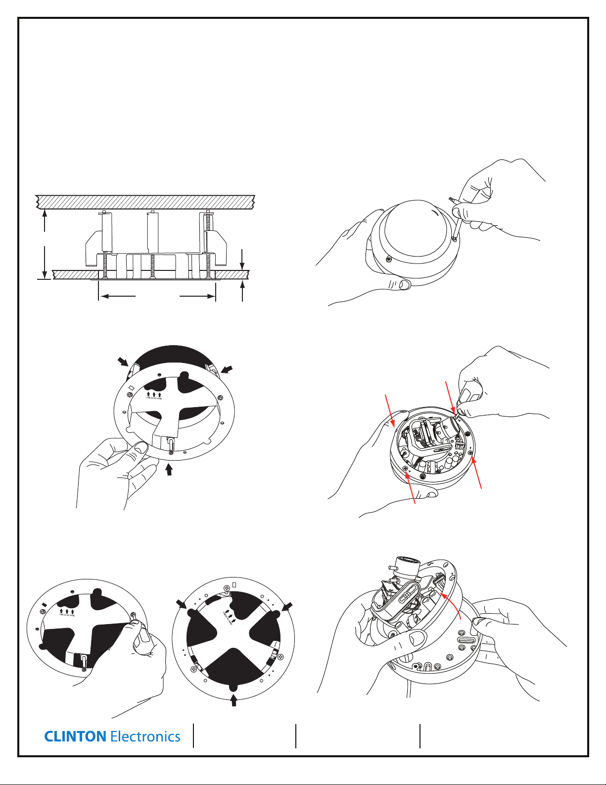
1. Preparing Mounting Surface
The VXRM requires a minimum of 3” depth and can be installed on mounting
surfaces up to 1-1/4“ thick. Cut a hole in your mounting surface using a 5-1/2”
hole saw.
3. Opening the Case
Use the supplied Torx wrench to remove the 3 Torx screws that hold the
dome assembly onto the base
3” Min Depth
5-1/2” Hole
2. Installing the Recess Mount
Fold the wings inward to slide the Recess Mount into the 5-1/2” hole.
1-1/4” Max Mounting
Material Depth
Locate and remove the 4 Phillips head screws that hold the inner case
onto the camera base. Note: Arrowheads indicate screw location.
With a Phillips head screwdriver, rotate the three screws clockwise to ip the tension
wings out until they rmly grip the mounting material. NOTE: When mounting, make
sure the mounting surface does not block the three perimeter holes shown below.
These holes must be clear in order to accept the VX case in the next steps.
CLINTON Electronics
6701 Clinton Road
Loves Park, IL 61111
Remove the camera assembly from the camera base as shown below.
Set this base aside. You will not need this base when using the Recess Mount.
1.800.447.3306 Sales
1.800.549.6393 Support
1.800.633.8712 Fax
www.clintonelectronics.com
v.05.24.11
Page 2
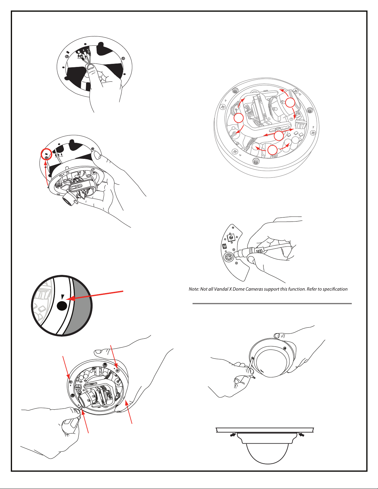
3. Mounting the Camera
Feed the power and video cables through the
“CABLES GO HERE”.
Align the tab with the slot when reassembling.
hole marked
Adjustment:
The Vandal X Dome Camera has four position adjustments:
A. Barrel rotation
B. Lens angle
C. Lateral adjustment (loosen thumb screws on each side to adjust)
D. Camera plate rotation (pinch the camera bracket by each thumb screw to
rotate clockwise or counterclockwise)
B
A
C
D
Testing:
Before replacing the dome cover you may wish to test the camera with a test
monitor. To test, plug in the CE-REMOTE into the DIN connection shown below
and connect your test monitor to the BNC connection located on the CE-REMOTE
cable. Refer to camera manual for detailed OSD adjustment settings.
Replace the four screws that hold the camera assembly to the base.
Note: Arrowheads indicate screw location.
Arrowhead indicates
screw location.
UP
RIGHT
LEFT
DOWN
for OSD Adjustment & Test Monitor Connection compatibility.
Tighten the 3 Torx screws that hold the dome cover onto the base to complete
installation. Make sure that each screw is tight to ensure superior weather resistance.
NOTE: Due to the replacement of the bottom case, a 1/16” gap between the
VXRM and the VX camera dome will result. This will not aect the IP68 weather
rating of the VX series camera.
 Loading...