


Public View
CE-M8SD-B
User Manual
|
|
CLINTON Electronics |
|
1.800.447.3306 Sales |
|
|
|
|
|
||
|
|
6701 Clinton Road |
|
1.800.549.6393 Support |
www.clintonelectronics.com |
|
|
Loves Park, IL 61111 |
|
1.800.633.8712 Fax |
|

Table of Contents
Display Introduction………………………………………………………………………… 3
Contents, Installation and Set-up……………………………………………………4
Display Functions…………………………………………………………………… 5
LCD Remote Control………………………………………………………………… 6
Display System Settings……………………………………………………………7-8
SD-Card Files………………………………………………………………………… 9
|
|
|
|
|
|
DVR |
|
|
|
DVR Remote Control……………………………………………………………… |
10 |
|||
|
|
|
DVR Settings………………………………………………………………………… |
|
|
|
|
Playback…………………………………………………………………………… |
11 |
|
|
|
12 |
|
|
|
|
Main menu, Date & Time……………………………………………………………13 |
|
|
|
|
Motion Detection…………………………………………………………………… |
|
|
|
|
Recording Mode………………………………………………………………… |
14 |
|
|
|
|
|
|
|
15-16 |
||
|
|
|
Continuous Recording, DVR SD-Card Options…………………………………… |
17 |
|
|
|
System Status, Power-On Setup, Factory Default………………………………… |
18 |
Camera Camera OSD Menu………………………………………………………………… 19 OSD Menu Navigation, Lens……………………………………………………… 20 Exposure…………………………………………………………………………… 21 White Balance……………………………………………………………………… 22 SSDR…………………………………………………………………………………23 BLC, HLC…………………………………………………………………………… 24 HLC………………………………………………………………………………… 25 DNR3……………………………………………………………………………… 26 Day/Night.………………………………………………………………………… 27 Special
Image Adjust……………………………………………………………… 28 Image Adj. (continued), Monitor……………………………………… 28-29 Camera Title…………………………………………………………………30 Sync, Motion Detection…………………………………………………… 31 Motion (continued), Privacy……………………………………………… 32 Comm Adj. (continued), Language, Return, Exit………………………… 33
Troubleshooting ……………………………………………………………… 34-35
2
Introduction
Congratulations on the purchase of your new Public View Integrated Camera Security display. This display and camera combination is designed for simple and effective loss prevention by making the viewer aware of video surveillance measures.
Features:
•Rugged Steel Enclosure
•SD-Card Player
•Single Channel DVR with SD-Card Storage
•Motion Detection
•LowVoltage power
•Integrated High-Resolution Digital Day & Night Camera (600TVL)
•VESA mounting pattern for ceiling or wall mount options
•Remote control operation of all screen adjustment features
•Wide viewing angles
•Video Output
Precautions
•There are no user serviceable parts inside the unit. Authorized service personnel must perform all service.To avoid electrical shock, do not disassemble the unit. Any attempt to disassemble the unit will void the warranty.
•Verify DC power supply before installation.This unit requires an external AC to DC power supply capable of supplying sufficient DC voltage to the display.
•Install the monitor in a location that is suitable for the display. Make sure there is adequate ventilation around the unit, and that the display is mounted securely to its support structure.
•Do not place the monitor in direct sunlight, or near sources of heat.
•Do not place the monitor in a damp area.
•Do not place the monitor in an area that is below 40˚F.
•Clean the monitor with water or non-ammonia glass cleaners only. Do not use abrasive cleaners, abrasives, or highly concentrated ammonia to clean the front of the display. Clean with a damp cloth only, do not spray directly with water.
3
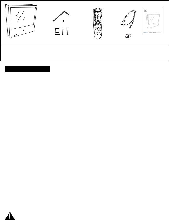
PACKAGE CONTENTS
16 SD Card
GB
2GB
SD Card
CE-M8SD-B with access door and
security screw
Security AllenWrench
Extra Security Screw
16 GB SD-Card (for DVR)
2 GB SD-Card (for media)
Remote Control |
Power Pigtail |
User Manual |
(batteries included) |
(for Hardwiring) |
|
|
Alarm Plug |
|
Installation and Set up
Unpacking your display
Your Public View display comes with all of the items shown above. Carefully remove the display from its packing and set the unit on a firm surface. Save the packing in case of future service requirements.
Installation of the display
The display should be located where it will have the most effect on deterring potential shoplifting. Keep in mind the lighting conditions, viewing area, ease of installation, and distance from the power supply when choosing a location. The display is compatible with many available wall and ceiling mounts, consult your dealer for suggestions. The rear of the display has a VESA 75mm & 100mm mounting patterns that accepts M4x8mm screws. Please refer to the installation instructions on the particular mounting bracket and details of how to install.
Connecting the display
This display requires a 24V DC power supply. Locate the applicable AC to DC power supply in a suitable location where there is a power source, and access to run the low voltage cable to the display.
For single unit power supplies, you will need to keep the distance from the power supply to the display less than 75 ft. For multiple unit power supplies, the power supply can be located at further distances from the displays at a central location. Please refer to the specific power supply installation instructions for recommended wire size and distances.
Caution: Do not connect the power connector to the display when energized, doing so may damage the electronics inside the display. Connect power supply to unit, then to 120v wall outlet.
4

Display Functions
Features
|
Video |
|
SD-card slot |
|
DVR SD-card slot |
|
Camera |
LED Flasher |
Camera OSD Joystick |
|
|
|
IR Sensor |
VESA 75 & VESA 100
 mounting patterns

 Power Supply Input

 BNC Output
 Alarm Connection
Control Access
The access door for the OSD Joystick, SD-Cards, and Connections is located on the back of the unit and must be removed using the included security allen wrench.
5
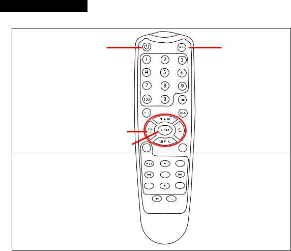
Remote Control - LCD
The parameters of the display can be adjusted by using the included remote control.
LCD CONTROLS
Power |
Mute |
Selection Arrows
Menu
DVR |
AV |
DVR CONTROLS |
REC |
(see page 10 for DVR controls) |
|
|
MENU |
Exit |
OSD |
|
SOURCE |
912-F8125-0001
LCD CONTROLS
Power – On/Off function. This will power off the display only. The internal camera can still supply video to an external display or DVR.
Mute –Disables the audio on the unit.
Menu – Adjustment of audio, video, signal, tools, & language.
•Push MENU button once.
•Use arrow buttons located around the MENU button to pick category.
•When correct category is chosen, pressVOLandVOL+ buttons to adjust given parameter of display.
•When adjustment of selected parameter is done, press MENU to go back to the previous screen, or simply wait for the menu screen to time out.
Selection Arrows – Use in conjunction with the menu button to navigate and make adjustments.
6
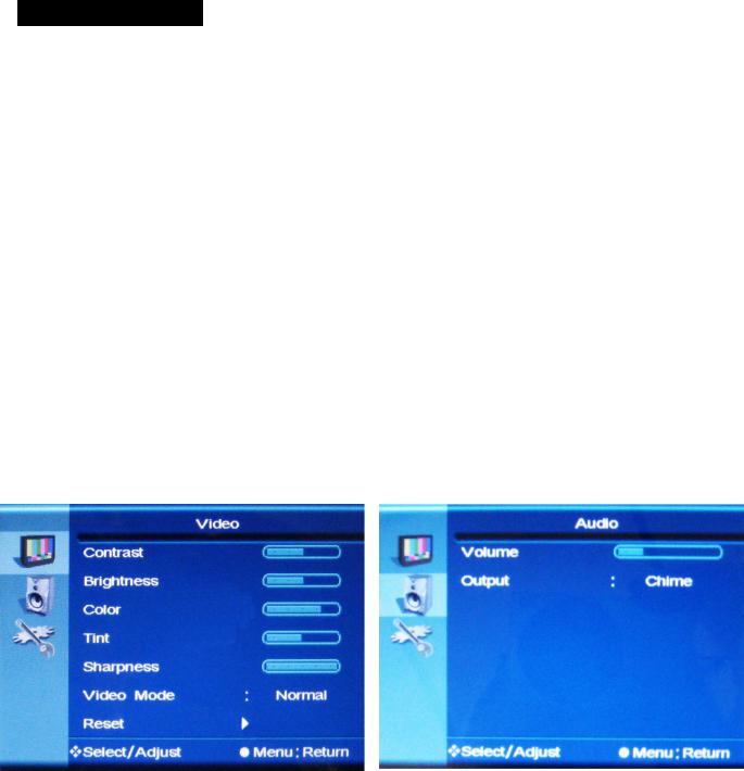
Display Set-Up
Video Menu: The display should be pre-set for most installations, however if some adjustment is necessary, we suggest you follow these recommendations by pressing the MENU button on the remote control:
1.First adjust the BRIGHTNESS control to set the black level so that the images are at their brightest while the black images are still black. Do not adjust too high where the black portions of the image become gray or the image will have a “washed out” appearance.
2.Set the CONTRAST control to set the white level so that the images are at their brightest without losing definition in the white portions of the image.
3.Adjust the COLOR control to achieve a realistic image of the items within the viewing area.
4.Adjust the TINT control if the image has bluish or reddish tint to the white portions of the image.
5.Decrease the SHARPNESS if the image appears too grainy or pixelated. Increase the SHARPNESS if the image appears too soft.
6.With VIDEO MODE, you can select from various preset configurations. These include Normal, Nature, Cinema, Sport, Vivid.
7.The RESET function will reset the levels in the video menu only.
Audio Menu
1.The Audio Menu can be used to raise or lower the volume of the chime or SD-Card activated audio. *NOTE: The MUTE function on the remote control will disable the audio/chime sound.
2.Select the audio source by selecting CHIME to enable the built in chime sound, or SD-AUDIO for the audio on the SD-Card to play.
7
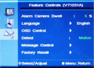
System Settings Menu
1.The ALARM CAMERA DWELL will allow you to change the duration that the camera image will remain on screen after an alarm event has occurred. If you wish to change this duration for motion events, you must do so in the DVR Settings menu. See pg. 16 for details.
2.The LANGUAGE can be changed to one of the following: English, French, German, Spanish, Italian, Dutch, Greek, Swedish.
3.In OSD CONTROL you can control the following:
3a. HORIZONTAL - Adjusts the horizontal position of the OSD. 3b. VERTICAL - Adjusts the vertical position of the OSD.
3c. ROTATION - Flips the OSD orientation to one of the following: Normal, Mirror, Left, Right, Down 3d. OSD TIMER - Set the duration the OSD menu will remain on screen after button is pressed.
4.With DETECT you can select for the camera image to show upon motion, or upon alarm event.
5.In the MESSAGE CONTROL section you can set the following:
5a. ON / OFF - Turns the message on the bottom of the screen on or off.
5b. MESSAGE - Select the message to read “WELCOME” or “RECORDING IN PROGRESS”. 5c. FLASH - Control the message to flash on and off, or be steady on.
5d. LED CONTROL - Disable or enable the flashing LED on the front of the device.
6. FACTORY RECALL will reset the device to the factory presets.
8
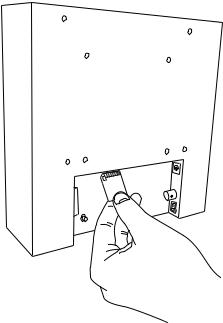
Change SD-Card Image/Video/Audio
•Insert the SD-Card into your computer or SD-Card reader.
•Move the desired JPEG image, or AVI video file into the SD-Card folder.
(For the M8SD-B the desired full screen image size is 800x600)
•Leaving multiple media files on the SD-Card will result in the device cycling through all loaded media.
•Insert the SD-Card back into the PVM with the contacts facing out, as shown on the right-
DO NOT FORCE IT IN.
*NOTE: If you wish to not display SD-Card content, you must set“Alarm Camera Dwell”to“On”, and “Detect”to“Alarm”
9
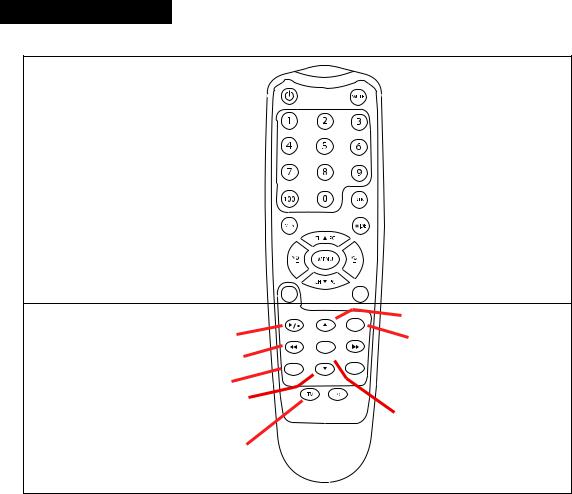
Remote Control -DVR
The parameters of the display can be adjusted by using the included remote control.
LCD CONTROLS
(see page 6 for LCD controls)
DVR |
AV |
DVR CONTROLS |
REC |
|
Play / Pause |
||
|
||
Back / Rewind |
MENU |
|
|
||
Exit |
OSD |
|
Exit / Stop |
|
|
Down |
SOURCE |
|
912-F8125-0001 |
||
Source |
|
|
Up
Record
 Forward / Fast Forward
 OSD Controls
Menu / OK
DVR CONTROLS
Play / Pause –Press once to play, press again to pause playback.
Menu/OK – Use to open Menu and to select functions.
Up, Down, Back, Forward Selection Arrows – Use in conjunction with the menu button to navigate and make adjustments. Also used to Fast Forward or Fast Reverse in playback mode.
OSD Controls – Toggles the OSD functions on screen.
Record – Not used (recording begins automatically when unit is on). To scheduling a recording see pg. 15.
Source – Press to toggle from DVR screen to live view.
Exit / Stop – Press to stop playback. Also used to exit the current selection to previous screen.
10
DVR Settings
Recording View
2011 |
1 |
2 |
3 |
4 |
5 |
6 |
7 |
8 |
9 |
720480 HQ
1 |
Current Date & Time |
Select from: Yr / Mo / Day |
or Mo / Day /Yr, |
HOUR : MINUTE : SECOND |
||
|
|
|
|
|
|
|
2 |
Record Status |
|
Device is Recording Data |
|
|
|
|
|
|
|
|
|
|
3 |
Record Mode |
|
Manual Record |
Schedule Record |
Motion Record |
|
|
|
|
|
|
|
|
4 |
Video Size |
360 |
Quarter VGA Quality |
720 |
VGA Quality |
|
|
|
240 |
360 x 240 |
480 |
720 x 480 |
|
5 |
Recording Quality |
BQ Basic Quality NQ Normal Quality |
HQ High Quality |
|||
|
|
|
||||
6 |
Audio Status |
No Audio recording supported with this device (Disregard Audio Symbol) |
||||
|
|
|
|
|
||
7 |
SD Card Status |
|
DVR SD Card Present |
DVR SD Card NOT Present |
||
|
|
|
|
|
|
|
|
|
|
“Loop” Mode |
|
“Stop” Mode |
|
8 |
Record Storage Mode |
|
Overwrite is Active |
0% Shows % of Storage Space Used |
||
9 |
Battery Level |
|
Battery Level is not supported with this device (Disregard this symbol) |
|||
|
|
|
|
|
|
|
11
 Loading...