


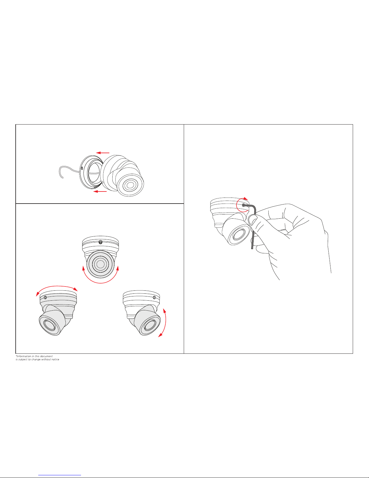
With the supplied 2mm Allen Wrench, loosen the two set screws located near the base, on the outer
camera housing. Remove mounting plate from the camera housing.
1. DISASSEMBLE CAMERA
Attach the mounting plate to the desired surface with the three provided 3x13mm Phillips head screws.
Drill a 3/4” hole in the opening of the mounting plate if running the cable through the mounting surface.
2. ATTACH MOUNTING PLATE
Camera settings can be adjusted by using the Built-in Joystick located on the cable. Connect your test
monitor to either the analog or HD-SDI BNC connection located on the CE-T100HD cable. Refer to OSD
Manual for detailed instructions on adjusting camera settings.
Feed the cables through the center of the mounting plate. Make connections to the BNC cable and the
power connection. To ensure quality operation, verify proper BNC and power termination; along with
proper voltage at camera.
3. CONNECT POWER SUPPLY
4. OSD MENU
CE-T100HD Install Guide
v.04.13.15
Included Items:
• CE-T100HD x 1
• 3x13mm Phillips Head Screws x3
• 2mm Allen Wrench x1
• OSD Manual x1
Required Items
• Phillips Head Screwdriver x1
• Drill x1
• 3/4” Drill Bit x1
Optional Items:
• Test Monitor
clintonelectronics
| 6701 Clinton Road Loves Park, IL 61111 | 800.447.3306 (Sales) | 800.549.6393 (Support) | www.clintonelectronics.com
Inferior quality coax cable or excessively long runs of cable will cause the HD-SDI video signal to be poor or not viewable. It is
recommended to test all coax cable to be used as HD-SDI with a HD-SDI Cable Tester
USING A 24 VOLT POWER SUPPLY WILL CAUSE DAMAGE
TO THE CAMERA AND CAN CAUSE POTENTIAL FIRE OR
ELECTRIC SHOCK HAZARDS.
Test Monitor
TO CAMERA
HD-SDI BNC
CONNECTION (BLACK)
ANALOG BNC
CONNECTION (YELLOW)
12V POWER
CONNECTION
TO DVR
OR
MONITOR
Mounting Plate
Feed any cable slack into the mounting surface. Place the camera housing onto the mounting plate and
partially tighten the set screws on the outer camera housing. Do not fully tighten yet. The camera
housing needs to be loose to make camera position adjustments in the next step.
5. MOUNT CAMERA
The camera view can be adjusted by turning the camera housing to the desired location. Lens angle can
be adjusted by tilting to the desired location. Barrel rotation can be adjusted by rotating the camera
body to the desired position.
6. CAMERA ADJUSTMENTS
After camera adjustments have been made, tighten the set screws to fully secure the camera housing to
the mounting plate.
7. TIGHTEN SET SCREWS
v.04.13.15
clintonelectronics
| 6701 Clinton Road Loves Park, IL 61111 | 800.447.3306 (Sales) | 800.549.6393 (Support) | www.clintonelectronics.com
360˚
360˚
90˚
BARREL ROTATION
LENS ROTATION
CAMERA VIEW
 Loading...