

Page 1
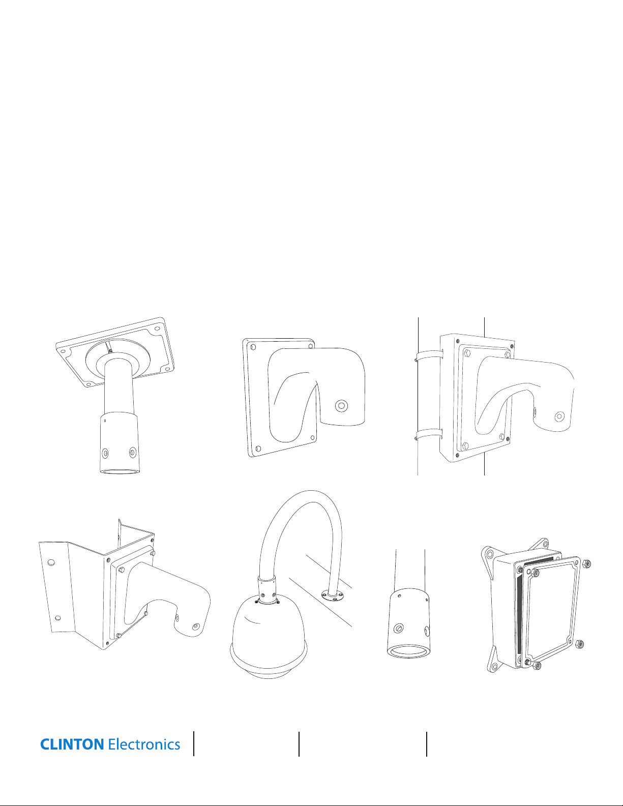
PTZ Mounts
1 2 3 4 5 6 7 8 9 10 11 12 13 14 15 16 17 18 19
H&F
AC24V
AUX1
AUX2
COM
ALM1
ALM2
ALM3
ALM4
ALM5
ALM6
ALM7
485A
485B
485A
485B
AC24V
AC220V
AC220V
COM
JP2
JP2_2
AC24V FUSE
J1
FUSE
5X20
Outdoor Box
Model CE-PTZ-WP24
0204201792
1 2 3 4 5 6 7 8 9 10 11 12 13 14 15 16 17 18 19
H&F
AC24V
AUX1
AUX2
COM
ALM1
ALM2
ALM3
ALM4
ALM5
ALM6
ALM7
485A
485B
485A
485B
AC24V
AC220V
AC220V
COM
JP2
JP2_2
AC24V FUSE
J1
FUSE
5X20
Outdoor Box
Model CE-PTZ-WP24
0204201792
CE-PTZ-IP
CE-PTZ-WM
CE-PTZ-POLE
CE-PTZ-CR
CE-PTZ-PARAPET
CE-PTZ-PA
CE-PTZ-WP24/COVER
User Manual
CLINTON Electronics
6701 Clinton Road
Loves Park, IL 61111
1.800.447.3306 Sales
1.800.549.6396 Support
1.800.633.8712 Fax
www.clintonelectronics.com
v.07.20.10
Page 2
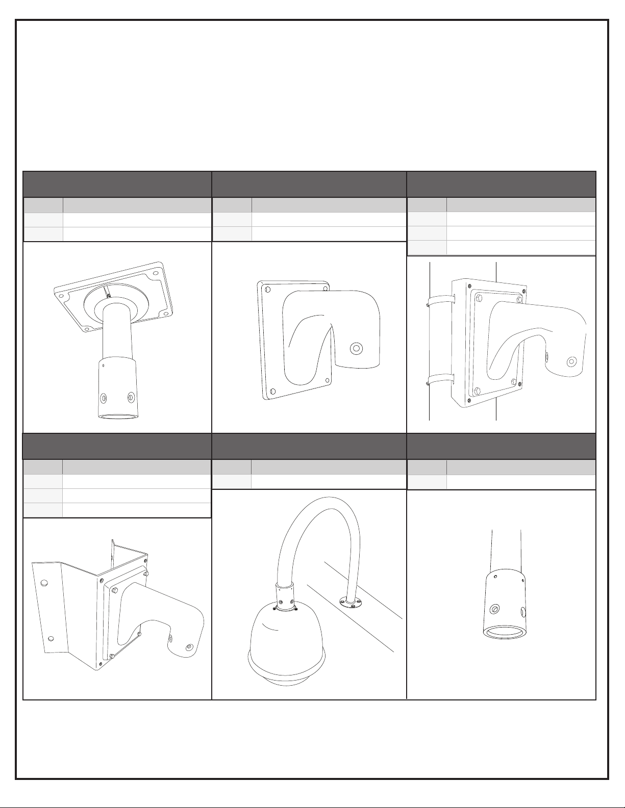
Mount Guide
Required Components to attach PTZ Camera
Ceiling
Ceiling Required Components to attach PTZ
1. (CE-PTZ-IP) Ceiling Mount
2. (CE-PTZ-WP24) Outdoor Box - OPTIONAL
Corner
Corner Required Components to attach PTZ
1. (CE-PTZ-CR) Corner Mount
2. (CE-PTZ-WM) Wall Mount
3. (CE-PTZ-WP24) Outdoor Box - OPTIONAL
Wall
Wall Required Components to attach PTZ
1. (CE-PTZ-WM) Wall Mount
2. (CE-PTZ-WP24) Outdoor Box - OPTIONAL
Parapet
Parapet Required Components to attach PTZ
1. (CE-PTZ-PARAPET) Parapet Mount
Pole
Pole Required Components to attach PTZ
1. (CE-PTZ-POLE) Pole Mount
2. (CE-PTZ-WM) Wall Mount
3. (CE-PTZ-WP24) Outdoor Box - OPTIONAL
Pipe
Pipe Required Components to attach PTZ
1. (CE-PTZ-PA) Mount Adaptor
Page 3
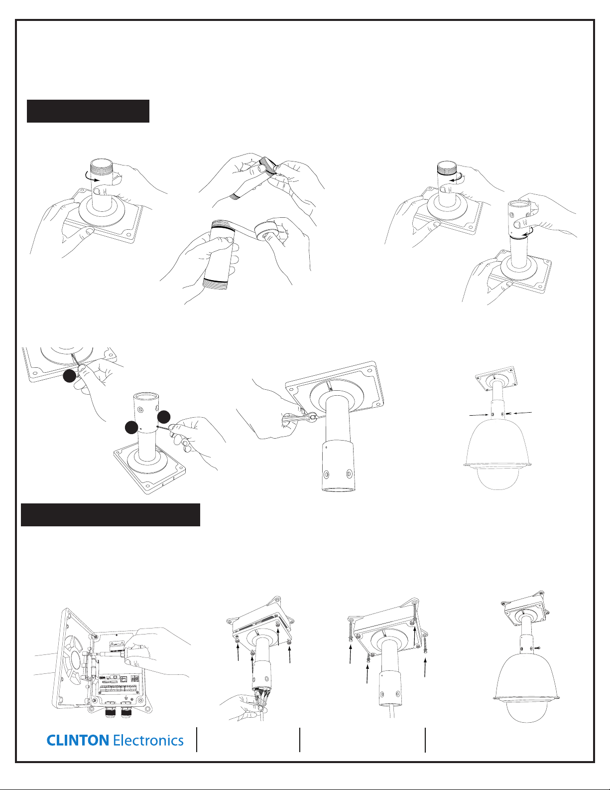
Outdoor Ceiling Mount
1 2 3 4 5 6 7 8 9 10 11 12 13 14 15 16 17 18 19
H&F
AC24V
AC24V
AC220V
Model CE-PTZ-WP24
1 2 3 4 5 6 7 8 9 10 11 12 13 14 15 16 17 18 19
H&F
AC24V
AC24V
AC220V
Model CE-PTZ-WP24
CE-PTZ-IP
Install Guide
Direct Mount
1. Unscrew Pipe from Base.
4. Insert thread set screws in their
appropriate locations (3 places).
1
2. Place rubber washer on each end
of the pipe, then wrap each end with
pipe thread tape.
5. Secure to mounting surface
using the appropriate mounting
hardware for your location.
3. Replace threaded pipe section into
the base, then screw on adaptor to
threaded pipe end.
6. Feed PTZ wires through the
mount assembly, and bolt to mount
using the supplied bolts and washers.
3
2
Outdoor Box Mount
Follow steps 1 through 4 above to
assemble the CE-PTZ-IP, then follow
these steps to mount the outdoor box.
1. Connect Outdoor Box to the
mount using the supplied screws.
2. Feed the PTZ wires though
the mount and make connections. Close the mount
onto the box and secure using supplied lock nuts.
3. Secure assembly
to mounting surface
using appropriate
hardware.
4. Feed any excess wires into
mount assembly, and bolt to
mount using supplied bolts
and washers.
CLINTON Electronics
6701 Clinton Road
Loves Park, IL 61111
1.800.447.3306 Sales
1.800.549.6396 Support
1.800.633.8712 Fax
www.clintonelectronics.com
07/20/10
Page 4

Outdoor Wall Mount
1 2 3 4 5 6 7 8 9 10 11 12 13 14 15 16 17 18 19
H&F
AC24V
AUX1
AUX2
COM
ALM1
ALM2
ALM3
ALM4
ALM5
ALM6
ALM7
485A
485B
485A
485B
AC24V
AC220V
AC220V
COM
JP2
JP2_2
AC24V FUSE
J1
FUSE
5X20
Outdoor Box
Model CE-PTZ-WP24
0204201792
1 2 3 4 5 6 7 8 9 10 11 12 13 14 15 16 17 18 19
H&F
AC24V
AUX1
AUX2
COM
ALM1
ALM2
ALM3
ALM4
ALM5
ALM6
ALM7
485A
485B
485A
485B
AC24V
AC220V
AC220V
COM
JP2
JP2_2
AC24V FUSE
J1
FUSE
5X20
Model CE-PTZ-WP24
1 2 3 4 5 6 7 8 9 10 11 12 13 14 15 16 17 18 19
H&F
AC24V
AUX1
AUX2
COM
ALM1
ALM2
ALM3
ALM4
ALM5
ALM6
ALM7
485A
485B
485A
485B
AC24V
AC220V
AC220V
COM
JP2
JP2_2
AC24V FUSE
J1
FUSE
5X20
Model CE-PTZ-WP24
1 2 3 4 5 6 7 8 9 10 11 12 13 14 15 16 17 18 19
H&F
AC24V
AC24V
AC220V
Model CE-PTZ-WP24
1 2 3 4 5 6 7 8 9 10 11 12 13 14 15 16 17 18 19
H&F
AC24V
AC24V
AC220V
JP2
JP2_2
AC24V FUSE
FUSE
5X20
Model CE-PTZ-WP24
1 2 3 4 5 6 7 8 9 10 11 12 13 14 15 16 17 18 19
H&F
AC24V
AC24V
AC220V
Model CE-PTZ-WP24
1 2 3 4 5 6 7 8 9 10 11 12 13 14 15 16 17 18 19
H&F
AC24V
AC24V
AC220V
Model CE-PTZ-WP24
1 2 3 4 5 6 7 8 9 10 11 12 13 14 15 16 17 18 19
H&F
AC24V
AUX1
AUX2
COM
ALM1
ALM2
ALM3
ALM4
ALM5
ALM6
ALM7
485A
485B
485A
485B
AC24V
AC220V
AC220V
COM
JP2
JP2_2
AC24V FUSE
J1
FUSE
5X20
Outdoor Box
Model CE-PTZ-WP24
0204201792
1 2 3 4 5 6 7 8 9 10 11 12 13 14 15 16 17 18 19
H&F
AC24V
AUX1
AUX2
COM
ALM1
ALM2
ALM3
ALM4
ALM5
ALM6
ALM7
485A
485B
485A
485B
AC24V
AC220V
AC220V
COM
JP2
JP2_2
AC24V FUSE
J1
FUSE
5X20
Outdoor Box
Model CE-PTZ-WP24
0204201792
CE-PTZ-WM
Install Guide
Direct Mount
1. Secure to mounting surface us-
ing appropriate mounting hardware.
Outdoor Box Mount
1. Secure the boxes hinge to the
wall mount bracket using the
supplied screws.
2. Feed PTZ wires through the
mount assembly, and bolt to mount
using the supplied bolts.
2. Feed PTZ wires though
mount and make connections. Close the mount
onto the box and secure
3. Attach to mounting surface using
appropriate mounting hardware.
together using the supplied lock nuts.
4. Feed PTZ wires through
the mount assembly, and
bolt to mounting bracket
using the supplied bolts
and washers.
CLINTON Electronics
6701 Clinton Road
Loves Park, IL 61111
1.800.447.3306 Sales
1.800.549.6396 Support
1.800.633.8712 Fax
www.clintonelectronics.com
07/20/10
Page 5

Pole Mount
1 2 3 4 5 6 7 8 9 10 11 12 13 14 15 16 17 18 19
H&F
AC24V
AC24V
AC220V
Model CE-PTZ-WP24
1 2 3 4 5 6 7 8 9 10 11 12 13 14 15 16 17 18 19
H&F
AC24V
AUX1
AUX2
COM
ALM1
ALM2
ALM3
ALM4
ALM5
ALM6
ALM7
485A
485B
485A
485B
AC24V
AC220V
AC220V
COM
JP2
JP2_2
AC24V FUSE
J1
FUSE
5X20
Outdoor Box
Model CE-PTZ-WP24
0204201792
1 2 3 4 5 6 7 8 9 10 11 12 13 14 15 16 17 18 19
H&F
AC24V
AUX1
AUX2
COM
ALM1
ALM2
ALM3
ALM4
ALM5
ALM6
ALM7
485A
485B
485A
485B
AC24V
AC220V
AC220V
COM
JP2
JP2_2
AC24V FUSE
J1
FUSE
5X20
Outdoor Box
Model CE-PTZ-WP24
0204201792
1 2 3 4 5 6 7 8 9 10 11 12 13 14 15 16 17 18 19
H&F
AC24V
AUX1
AUX2
COM
ALM1
ALM2
ALM3
ALM4
ALM5
ALM6
ALM7
485A
485B
485A
485B
AC24V
AC220V
AC220V
COM
JP2
JP2_2
AC24V FUSE
J1
FUSE
5X20
Model CE-PTZ-WP24
1 2 3 4 5 6 7 8 9 10 11 12 13 14 15 16 17 18 19
H&F
AC24V
AUX1
AUX2
COM
ALM1
ALM2
ALM3
ALM4
ALM5
ALM6
ALM7
485A
485B
485A
485B
AC24V
AC220V
AC220V
COM
JP2
JP2_2
AC24V FUSE
J1
FUSE
5X20
Model CE-PTZ-WP24
1 2 3 4 5 6 7 8 9 10 11 12 13 14 15 16 17 18 19
H&F
AC24V
AUX1
AUX2
COM
ALM1
ALM2
ALM3
ALM4
ALM5
ALM6
ALM7
485A
485B
485A
485B
AC24V
AC220V
AC220V
COM
JP2
JP2_2
AC24V FUSE
J1
FUSE
5X20
Outdoor Box
Model CE-PTZ-WP24
0204201792
1 2 3 4 5 6 7 8 9 10 11 12 13 14 15 16 17 18 19
H&F
AC24V
AUX1
AUX2
COM
ALM1
ALM2
ALM3
ALM4
ALM5
ALM6
ALM7
485A
485B
485A
485B
AC24V
AC220V
AC220V
COM
JP2
JP2_2
AC24V FUSE
J1
FUSE
5X20
Outdoor Box
Model CE-PTZ-WP24
0204201792
CE-PTZ-POLE
Install Guide
Direct Mount
2. Place mount on pole
and wrap cable straps
around pole. Retighten
1. Loosen Cable ties
Outdoor Box Mount
Follow steps 1 through 2 above to assemble the CE-PTZ-POLE, then follow these
steps to mount the outdoor box.
straps until snug.
3. Attach Outdoor Wall
Mount (CE-PTZ-WM),
using the supplied bolts,
and feed PTZ wires
though mount assembly.
3. Attach Outdoor Wall
Mount (CE-PTZ-WM),
using the supplied bolts
and washers.
1. Secure the boxe’s hinge to the
wall mount bracket.
2. Feed PTZ wires though
mount and make connections. Close the mount
onto the box and secure
together using the supplied lock nuts.
CLINTON Electronics
6701 Clinton Road
Loves Park, IL 61111
3. Bolt the outdoor
box assembly to the
pole mount using the
supplied bolts and
washers.
1.800.447.3306 Sales
1.800.549.6396 Support
1.800.633.8712 Fax
4. Feed PTZ wires through
the mount assembly, and
bolt to mount using the
supplied bolts.
www.clintonelectronics.com
07/20/10
Page 6

Corner Mount
1 2 3 4 5 6 7 8 9 10 11 12 13 14 15 16 17 18 19
H&F
AC24V
AC24V
AC220V
Model CE-PTZ-WP24
AUX2
485A
485B
485A
485B
AC24V
AC220V
AC220V
J1
AUX1
AUX2
485A
485B
485A
485B
AC24V
AC220V
AC220V
J1
FUSE
1 2 3 4 5 6 7 8 9 10 11 12 13 14 15 16 17 18 19
H&F
AC24V
AUX1
AUX2
COM
ALM1
ALM2
ALM3
ALM4
ALM5
ALM6
ALM7
485A
485B
485A
485B
AC24V
AC220V
AC220V
COM
JP2
JP2_2
AC24V FUSE
J1
FUSE
5X20
Model CE-PTZ-WP24
1 2 3 4 5 6 7 8 9 10 11 12 13 14 15 16 17 18 19
H&F
AC24V
AUX1
AUX2
COM
ALM1
ALM2
ALM3
ALM4
ALM5
ALM6
ALM7
485A
485B
485A
485B
AC24V
AC220V
AC220V
COM
JP2
JP2_2
AC24V FUSE
J1
FUSE
5X20
Model CE-PTZ-WP24
CE-PTZ-CR
Install Guide
Direct Mount
1. Attach mount using appropri-
ate mounting hardware for your
desired location.
Outdoor Box Mount
Follow step 1 above to mount the CE-PTZCR, then follow these steps to mount the
outdoor box.
2. Attach wall mount (CE-PTZ-WM)
to the corner mount using supplied
bolts and washers.
3. Feed PTZ wires through the mount
assembly, and bolt to mount using
the supplied bolts.
1. Secure the box’s hinge to the
wall mount bracket
2. Feed PTZ wires though
mount and make connections. Close the mount
onto the box and secure
together using the supplied lock nuts.
CLINTON Electronics
6701 Clinton Road
Loves Park, IL 61111
3. Bolt the outdoor
box assembly to the
corner mount using
the supplied bolts and
washers.
1.800.447.3306 Sales
1.800.549.6396 Support
1.800.633.8712 Fax
4. Feed PTZ wires
through the mount
assembly, and bolt
to mount using the
supplied bolts
www.clintonelectronics.com
07/20/10
Page 7

Parapet Mount
1 2 3 4 5 6 7 8 9 10 11 12 13 14 15 16 17 18 19
H&F
AC24V
AUX1
AUX2
COM
ALM1
ALM2
ALM3
ALM4
ALM5
ALM6
ALM7
485A
485B
485A
485B
AC24V
AC220V
AC220V
COM
JP2
JP2_2
AC24V FUSE
J1
FUSE
5X20
Outdoor Box
Model CE-PTZ-WP24
0204201792
1 2 3 4 5 6 7 8 9 10 11 12 13 14 15 16 17 18 19
H&F
AC24V
AUX1
AUX2
COM
ALM1
ALM2
ALM3
ALM4
ALM5
ALM6
ALM7
485A
485B
485A
485B
AC24V
AC220V
AC220V
COM
JP2
JP2_2
AC24V FUSE
J1
FUSE
5X20
Outdoor Box
Model CE-PTZ-WP24
0204201792
1 2 3 4 5 6 7 8 9 10 11 12 13 14 15 16 17 18 19
H&F
AC24V
AUX1
AUX2
COM
ALM1
ALM2
ALM3
ALM4
ALM5
ALM6
ALM7
485A
485B
485A
485B
AC24V
AC220V
AC220V
COM
JP2
JP2_2
AC24V FUSE
J1
FUSE
5X20
Outdoor Box
Model CE-PTZ-WP24
0204201792
1 2 3 4 5 6 7 8 9 10 11 12 13 14 15 16 17 18 19
H&F
AC24V
AUX1
AUX2
COM
ALM1
ALM2
ALM3
ALM4
ALM5
ALM6
ALM7
485A
485B
485A
485B
AC24V
AC220V
AC220V
COM
JP2
JP2_2
AC24V FUSE
J1
FUSE
5X20
Outdoor Box
Model CE-PTZ-WP24
0204201792
1 2 3 4 5 6 7 8 9 10 11 12 13 14 15 16 17 18 19
H&F
AC24V
AUX1
AUX2
COM
ALM1
ALM2
ALM3
ALM4
ALM5
ALM6
ALM7
485A
485B
485A
485B
AC24V
AC220V
AC220V
COM
JP2
JP2_2
AC24V FUSE
J1
FUSE
5X20
Outdoor Box
Model CE-PTZ-WP24
0204201792
1 2 3 4 5 6 7 8 9 10 11 12 13 14 15 16 17 18 19
H&F
AC24V
AUX1
AUX2
COM
ALM1
ALM2
ALM3
ALM4
ALM5
ALM6
ALM7
485A
485B
485A
485B
AC24V
AC220V
AC220V
COM
JP2
JP2_2
AC24V FUSE
J1
FUSE
5X20
Outdoor Box
Model CE-PTZ-WP24
0204201792
AUX1
AUX2
485A
485B
485A
485B
AC24V
AC220V
AC220V
J1
FUSE
AUX1
AUX2
485A
485B
485A
485B
AC24V
AC220V
AC220V
J1
FUSE
1 2 3 4 5 6 7 8 9 10 11 12 13 14 15 16 17 18 19
H&F
AC24V
AUX1
AUX2
COM
ALM1
ALM2
ALM3
ALM4
ALM5
ALM6
ALM7
485A
485B
485A
485B
AC24V
AC220V
AC220V
COM
JP2
JP2_2
AC24V FUSE
J1
FUSE
5X20
Outdoor Box
Model CE-PTZ-WP24
0204201792
1 2 3 4 5 6 7 8 9 10 11 12 13 14 15 16 17 18 19
H&F
AC24V
AUX1
AUX2
COM
ALM1
ALM2
ALM3
ALM4
ALM5
ALM6
ALM7
485A
485B
485A
485B
AC24V
AC220V
AC220V
COM
JP2
JP2_2
AC24V FUSE
J1
FUSE
5X20
Outdoor Box
Model CE-PTZ-WP24
0204201792
CE-PTZ-PARAPET
Install Guide
1. Feed the supplied PTZ extension cord through the parapet
mount.
Mount Adaptor
CE-PTZ-PA
Install Guide
1. Place the supplied
rubber gasket between the mounting
surface and the parapet mount.
2. Attach the mount using appropriate mounting hardware for your
location.
3. Connect PTZ wires to extension cord and feed excess wires
into the parapet mount, then
bolt PTZ to mount using the
supplied bolts and washers.
1. Wrap the end of the
threaded pipe with pipe
thread tape.
WP24 Cover
CE-PTZ-WP24/COVER
Install Guide
1. Place the cover over the
bolts so it is tight against the
foam seal. Apply the lock
nuts and tighten.
2. Screw on mount
adaptor to threaded
pipe end.
3. Insert set screws in
their appropriate locations (2 places).
1
2
4. Feed PTZ wires through the
mount assembly, and bolt PTZ
to mount using the supplied
bolts and washers.
CLINTON Electronics
6701 Clinton Road
Loves Park, IL 61111
1.800.447.3306 Sales
1.800.549.6396 Support
1.800.633.8712 Fax
www.clintonelectronics.com
07/20/10
Page 8

v.07.20.10
8
 Loading...