

Page 1
Public View Monitor
Manual
CE-M10A
v08.15.16
6701 Clinton Road Loves Park, IL 61111 | 800.447.3306 (Sales) | 800.549.6393 (Support) | www. clintonelectronics.com
Page 2

Warning & Compliance
1
Important Safeguards
Hardware Overview
PVM Exterior
Back Panel Connections
Table Of Contents
Remote Control
Display Menu
OSD Menu Overview
Video Menu
Display Menu
Image Modes
Audio Menu
System Settings
SD Card
2
3
4
5
5
6
7
7
8
8-9
9
10
11
Camera Software
IP Installer - Windows
Web Viewer - Mac OSX
12
13-14
15-16
Page 3
The lightning flash with an arrowhead symbol,
RoHS
COMPLIANT
within an equilateral triangle is intended to alert
the user to the presence of uninsulated dangerous
voltage within the product’s enclosure that may
be of sucient magnitude to constitute a risk of
electric shock to persons.
The exclamation point within an equilateral triangle
is intended to alert the user to the presence of
important operating and maintenance (servicing)
instructions in the literature accompanying the
appliance.
INFORMATION - This equipment has been tested and found to comply with limits for a Class A digital device,
pursuant to part 15 of the FCC Rules. These limits are designed to provide reasonable protection against harmful
interference when the equipment is operated in a commercial environment. This equipment generates, uses,
and can radiate radio frequency energy and, if not installed and used in accordance with the instruction manual,
may cause harmful interference to radio communications. Operation of this equipment in a residential area is
likely to cause harmful interference in which case the user will be required to correct the interference at his own
expense.
WARN ING - Changes or modifications not expressly approved by the manufacturer could void the user’s
authority to operate the equipment.
CAUTION : To prevent electric shock and risk of fire hazards:
Do NOT use power sources other than that specified.
Do NOT expose this appliance to rain or moisture.
1
Warning & Compliance
This installation should be made by a qualified service person and
should conform to all local codes.
RoHS
This directive restricts the use of six hazardous materials in the manufacture of various
type of electronic and electrical equipment.
USA (FCC)
This device has been tested and found to comply with the limits of Class A computing
device pursuant to part 15 of the FCC rules.
Europe (CE)
By axing the CE marking, the manufacturer assures that the item meets all the essential
requirements of all applicable EU directives.
UL Listed
UL Listing means that UL has tested representative samples of the product and determined
that it meets UL’s requirements. These requirements are based primarily on UL’s published
and nationally recognized Standards for Safety..
Page 4

1. Read Instructions
All the safety and operating instructions should be
read before the appliance is operated.
2. Retain Instructions
The safety and operating instructions should be
retained for future reference.
3. Cleaning
Unplug this equipment from the wall outlet before
2
Important Safeguards
cleaning it. Do not use liquid aerosol cleaners. Use
a damp soft cloth for cleaning.
4. Attachments
Never add any attachments and/or equipment
without the approval of the manufacturer as such
additions may result in the risk of fire, electric
shock or other personal injury.
5. Water and/or Moisture
Do not use this equipment near water or in contact
with water.
6. Accessories
Do not place this equipment on an unstable cart,
stand or table. The equipment may fall, causing
serious injury to a child or adult, and serious
damage to the equipment. Wall or shelf mounting
should follow the manufacturer’s instructions,
and should use a mounting kit approved by the
manufacturer.
7. Power Sources
This equipment should be operated only from the
type of power source indicated on the marking
label. If you are not sure of the type of power,
please consult your equipment dealer or local
power company.
8. Power Cords
Operator or installer must remove power and
communications connections before handling the
equipment.
9. Lightning
For added protection for this equipment during a
lightning storm, or when it is left unattended and
unused for long periods of time, unplug it from
the wall outlet and disconnect the cable system.
This will prevent damage to the equipment due to
lightning and power-line surges.
D. If the equipment does not operate normally by
following the operating instructions, adjust only
those controls that are covered by the operating
instructions as an improper adjustment of other
controls may result in damage and will often
require extensive work by a qualified technician to
restore the equipment to its normal operation.
E. If the equipment has been dropped, or the
cabinet damaged.
F. When the equipment exhibits a distinct change
in performance —this indicates a need for service.
14. Replacement Parts
When replacement parts are required, be sure the
service technician has used replacement parts
specified by the manufacturer or that have the same
characteristics as the original part. Unauthorized
substitutions may result in fire, electric shock or
other hazards.
15. Safety Check
Upon completion of any service or repairs to this
equipment, ask the service technician to perform
safety checks to determine that the equipment is in
proper operating condition.
16. Field Installation
This installation should be made by a qualified
service person and should conform to all local
codes.
17. Correct Batteries
Warning: Risk of explosion if battery is replaced
by an incorrect type. Dispose of used batteries
according to the instructions.
18 . Tmra
A manufacturer’s maximum recommended ambient
temperature (Tmra) for the equipment must
be specified so that the customer and installer
may determine a suitable maximum operating
environment for the equipment.
19. Elevated Operating Ambient Temperature
If installed in a closed or multi-unit rack assembly,
the operating ambient temperature of the rack
environment may be greater than room ambient.
Therefore, consideration should be given to
installing the equipment in an environment
compatible with the manufacturer’s maximum rated
ambient temperature (Tmra).
10. Overloading
Do not overload wall outlets and extension cords as
this can result in the risk of fire or electric shock.
11. Objects and Liquids
Never push objects of any kind through openings
of this equipment as they may touch dangerous
voltage points or short out parts that could result
in a fire or electric shock. Never spill liquid of any
kind on the equipment.
12. Servicing
Do not attempt to service this equipment yourself.
Refer all servicing to qualified service personnel.
13. Damage Requiring Service
Unplug this equipment from the wall outlet and
refer servicing to qualified service personnel under
the following conditions:
A. When the power-supply cord or the plug has
been damaged.
B. If liquid is spilled, or objects have fallen into the
equipment.
C. If the equipment has been exposed to rain or
water.
20. Reduced Air Flow
Installation of the equipment in the rack should be
such that the amount of airflow required for safe
operation of the equipment is not compromised.
21. Mechanical Loading
Mounting of the equipment in the rack should be
such that a hazardous condition is not caused by
uneven mechanical loading.
22. Circuit Overloading
Consideration should be given to connection of
the equipment to supply circuit and the eect
that overloading of circuits might have on over
current protection and supply wiring. Appropriate
consideration of equipment nameplate ratings
should be used when addressing this concern.
23. Reliable Earthing (Grounding)
Reliable grounding of rack mounted equipment
should be maintained. Particular attention should
be given to supply connections other than direct
connections to the branch circuit (e.g., use of
power strips).
Page 5

Hardware Overview
1
Page 6
4
CAMERA
OSD
DC24V
VIDEO SD MEMORY
DO NOT REMOVE - CIF Memory
ALARM IN
ALARM OUT
OUTPUT
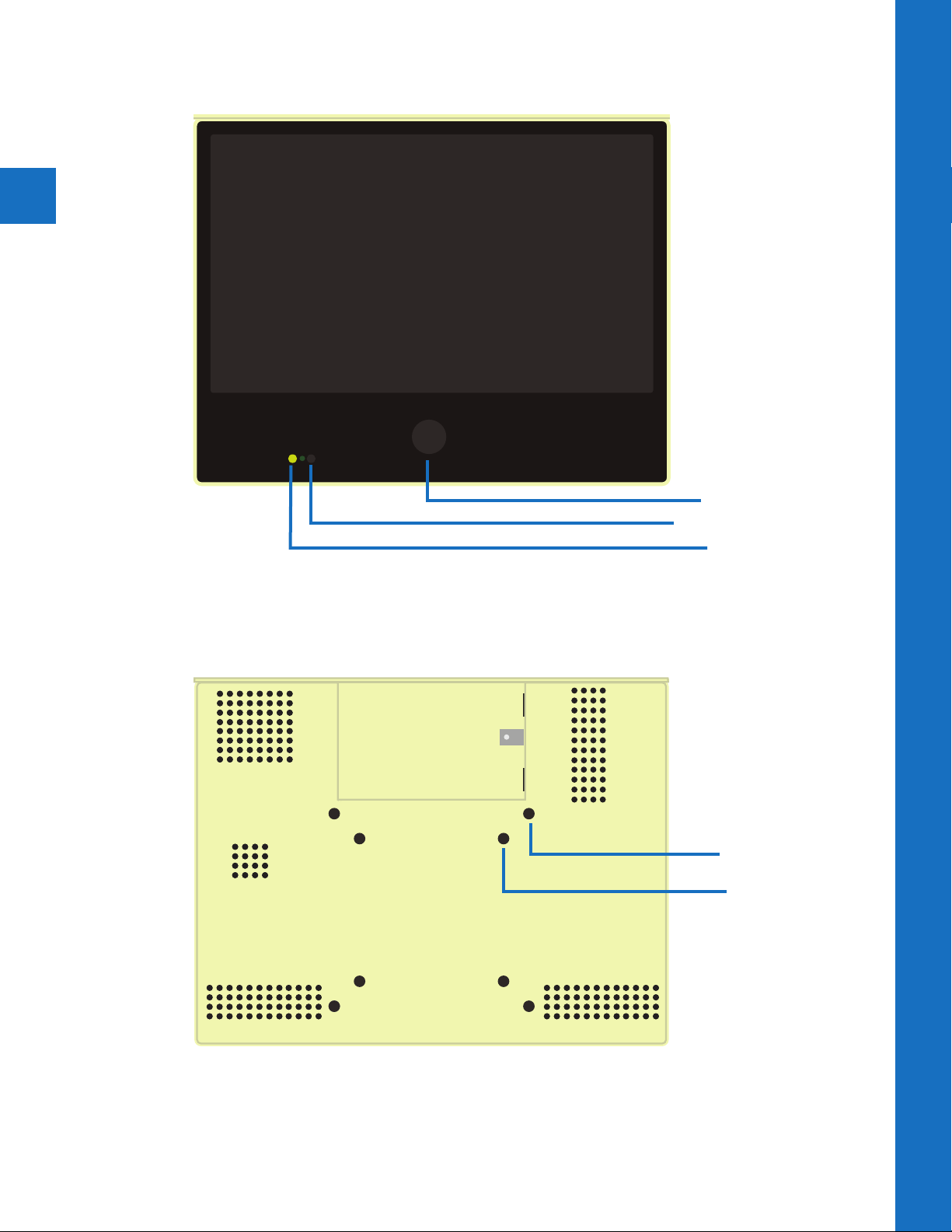
FRONT
Hardware Overview | Exterior
Camera Lens
Remote Receiver
LED Flasher
BACK
VIDEO SD MEMORY
DO NOT REMOVE - CIF Memory
DC24V
BNC
OUTPUT
LAN
(POE)
VESA 100
VESA 75
Page 7

DC24V
VIDEO SD MEMORY
DO NOT REMOVE - CIF Memory
LAN
(POE)
BNC
OUTPUT
BACK PANEL
SD Card
Warning! DO NOT POWER WITH 24V INPUT AND POE SIMULTANEOUSLY.
REMOTE CONTROL
VIDEO SD MEMORY
DO NOT REMOVE - CIF MEMORY
DC 24V
INPUT
BNC
OUTPUT
LAN
(POE)
DC 24V Input
BNC Out
Network Connection
Minumum 15W required for POE
POWER
Turns display On/O
5
Hardware Overview | Back-Panel Connections | Remote
MUTE
Turns audio On/O
MENU
Shows the On-Screen-
Display (OSD) Menu
ARROW BUTTONS
Navigates the OSD Menu.
Use Right or Left to change
a selection
EXIT
Closes the OSD Menu or
returns to previous menu
ENTER
Selects the highlighted OSD
Menu option. Press to make
adjustments or enter a
sub-menu
VOLUME
Raises or lowers volume
Note: All other buttons not described above are non-functioning for this device.
When the display is turned OFF, the camera will continue to supply video to a remote
display or DVR if connected.
Page 8

Display Menu
2
Page 9

OSD Menu
Using the remote control, or button pad located on the back of the device, press the Menu
button. The following selections will appear.
7
On-Screen-Display Menu
Video Display
Video: Adjust picture settings such as Contrast, Brightness, Saturation, Tint, Sharpness,
Color Temperature, and select from video image mode presets.
Display: Select Aspect Ratio, and select the Display Mode.
Audio: Raise or lower volume of SD Card content and built-in alarm.
System Settings: Change Language, OSD Settings, Key Lock, LED, and Message Control
settings.
Audio
System Settings
Video
• Contrast: Adjust to set the white level so that the images are at their brightest without
losing definition in the white portions of the image. Setting the too high will result in an
oversaturated image.
• Brightness: Adjust to set the black level so that the images are at their brightest while the
black portions are still black. Do not adjust too high where the black portions of the image
become gray or the image will have a “washed out” appearance.
• Saturation: Adjust to achieve a life-like separation between colors.
• Tint: Adjust if the image has bluish or reddish tint to the white portions of the image.
• Sharpness: Adjust lower if the image appears too grainy or pixilated. Increase if the image
appears too soft.
Advanced-
• Video Mode: Choose from preset video image modes (Normal, Cinema, Vivid, Natural).
• Color Temperature: Select from color temperature presets (Cool, Natural, Warm).
Page 10

Display
SD
SD
LOGO
SD
SD
SD
LOGO
SD
SD
8
• Aspect Ratio: Select the display aspect ratio (Full Screen, Cinema Scope, 4:3, Pillar Box
Expand, 1:1). Full Screen is the default setting and will display the image without stretching.
OSD Menu | Display
Use Cinema Scope for a more natural image and to stretch SD Card content to fill the screen.
• Image Mode: Select from the following 6 video display modes.
Note: Image modes which contain “VOV” refer to “Video-on-video”, where a smaller media
window shows on top of the main media content.
Camera- Displays live camera image only.
Switch- Switches from live camera to SD Card
content.
Switch is based upon Camera Time & SD Video Time
settings in the Switch Timer sub-menu.
Motion VOV Camera- Displays live camera full
screen. SD Card content will display in VOV window
when motion is sensed.
From the sub-menu, select the number of seconds
VOV window will remain on screen after motion is
sensed, as well as the VOV window size and position.
SD
SD
Page 11

LOGO
SD
SD
SD
SD
LOGO
SD
SD
LOGO
SD
SD
LOGO
SD
LOGO
SD
SD
SD
LOGO
SD
SD
LOGO
SD
SD
LOGO
SD
SD
LOGO
Motion VOV SD- Displays SD Card content full
screen. Live camera image will display in VOV
window when motion is sensed.
From the sub-menu, select the number of seconds
VOV window will remain on screen after motion
is sensed, as well as the VOV window size and
position.
Motion- Displays SD Card content full screen. Switches to full screen live video when
motion has been sensed.
SD-Video- Displays the SD Card content full screen. Camera’s video signal will continue to
output to an attached DVR or secondary display.
SD
SD
Sub Menu Selections:
Motion Dwell Time- Set number of seconds
live camera image will remain on screen
after motion is sensed.
9
OSD Menu | Image Modes | Audio
Audio
• Volume: Raise or Lower the volume for the SD Card content and chime. Alternatively, you
can use the volume buttons on the remote control to set volume level.
• Output: Choose the audio output signal (SD-Audio, Chime). Selecting Chime will play the
noise when motion is triggered. Note: Under the “Display” menu, “Image Mode” must be set
to a motion mode for Chime to play.
SD
Page 12

10
OSD Menu | System Settings
System Settings
• Language: Display the OSD menu in English or Spanish. Note: Changing the Language
does not change the flashing on-screen message. This must be changed in the Special
Control > Message setting.
• OSD Timer: Set the time in seconds before the OSD menu disappears. Turn timer OFF
to close the OSD menu upon exit button press only.
• OSD Transparency: Set the transparency level of the OSD menu.
• Key Lock: This selection is non-functioning on this model.
Special Control-
• Message On/O: Turn the on-screen message on or o.
• Message: Select from preset on-screen messages, or Anti-Theft graphic banner
Message Options: Recording in Progress, Welcome, Grabacion en Progresso,
Bienvenida). There are also two selections that alternate the English and Spanish
versions of these messages (Flash must be set to “ON” for these selections).
• Flash: Turning Flash “ON” enables the on-screen message to flash on and o. If
bilingual message is selected, this option must be “ON” to see message in both
languages.
• LED Control: Turn the Flashing LED on the front of the display on or o.
• LED Control with Panel: Use this in conjunction with the sleep timer. When this
feature is on, and the PVM enters sleep mode, the LED will turn on. Turn this setting
o in OSD menu to turn LED o.
• Image Orbit: Slightly shifts the screen image to prevent screen image burn-in.
• Motion Panel O Time: Puts the LCD to sleep when no motion is present for the set
number of minutes. LCD will turn back on when motion reoccurs.
• Recall: Pressing the right arrow button while recall is highlighted will reset the
display’s default factory settings. Resets Video, and select System Settings only. Does
not eect camera settings.
• Camera Reset: Pressing the right arrow button while Camera Reset is highlighted will
reset the IP camera settings including the Username and Password.
• Camera Default: Pressing the right arrow button while Camera Default is highlighted
will reset the camera to factory defaults. This does not eect Username and Password.
Page 13

Upload SD Card Content
The PVM is capable of displaying JPEG images or AVI video files from an SD Card. Before
loading files onto the SD Card, you MUST format the card to FAT-32. Failure to format the
SD Card may result in a black screen showing instead of the desired image or video.
The preferred JPEG image size is 1024 x 768. Load files directly onto the card. Do not place
files into folders. Skip to step 6 below for using JPEG images.
The preferred video format for Video is AVI with a maximum resolution size of 720 x 540. If
you already have a supported video, simply load it onto the SD Card.
To convert an unsupported video to the correct AVI format, follow the procedure below:
1. Download VLC
Download, install, & open the free program VLC. http://www.videolan.org/vlc/index.html
2. Convert
From the File menu select Convert/Stream.
3. Drop Media
Drag/Drop the desired video into the box that says “Drop Media Here”.
4. Choose Profile
A) Under Choose Profile, Click the Customize button. Select AVI under the
Encapsulation menu.
11
SD-Card
B) Click the Video codec tab, under the Codec dropdown, select DIVX 3.
In the Resolution field, enter 720 for width, and 540 for height.
Note: 640x480 will also work. (The Bitrate and Frame Rate should automatically
populate based on the quality of the original video).
C) Click Apply.
5. Choose Destination
Under Choose Destination, click Save File As > Browse to select the SD Card in which you
would like to save the file to. (Load files directly onto the card. Do not place files into
folders). Click Save when the progress bar has completed loading.
6. Insert Card into PVM
Insert the SD Card into the PVM with the contacts facing outward
(see image on right). Push the card down until it clicks into place.
7. Power Cycle
Power cycle the unit by unplugging the power cord, or pressing the
power button on the remote control.
Note: When an SD Card is inserted , you MUST power cycle the unit! Not doing so, may
result in corrupted SD Card which can eect PVM operation. Press power button on
remote control, or remove and replace power cord to power cycle.
8. Set Viewing Options
In the PVM’s OSD menu, under Display, make sure the image mode is set to a mode which
can display SD Card content.
Contacts Facing Out
Note: If using an Apple Computer, you will not be able to preview an AVI file.
Note: The SD Card player is not High Definition.
Note: If the video is not formatted/sized correctly (too large), the VOV window will display
a default blue or black screen.
Page 14

Camera Software
3
Page 15

IP Installer Software - Windows PC
To complete the installation of your IP camera based PVM,
follow the procedure below:
1. Install Software
After the PVM has been installed, download the installation
software by inserting the CD-ROM into a Windows PC. The
setup page will show up automatically. Select “Intelligent
IP Installer” and follow the on-screen installation process to
complete the installation.
For latest IP Installer software, visit the Support page on www.clintonelectronics.com
2. Open IP Installer
Click the Clinton Intelligent IP Installer Icon on your desktop. The main page will show up listing all
active camera and video server devices. Select the relevant IP camera from the list and double click
to enter the camera User Interface. The default web browser for viewing is Internet Explorer.
Note: Internet Expolrer is no longer supported on some devices. If you do not see the
camera’s image, then copy and paste the IP address URL into an alternate browser such as
Chrome, or Firefox.
13
IP Installer Software - Windows PC
3. Login to Camera
Enter Username and Password to login to the IP Camera. (Default is admin / admin). Then go to
Settings/Compatibility View. Type in the camera’s IP address and click ADD. Once the cameras IP
address has been added to the Compatibility View list, click CLOSE.
Note:
Default Username: admin
Default Password: admin
Page 16

14
4. Install ActiveX Control
When accessing the IP Camera for the first time, a yellow information bar appears below the address
bar: This website wants to install the following add-on: ‘AxvideoView.cab’ and/or ‘AxPlayer.cab’ from
‘Clinton Electronics’. Click Install.
5. Allow IP Camera Pop-Up’s
Depending on your computer’s Privacy settings, an information bar may appear alerting you about
blocking a pop-up. Choose to always allow for the IP camera address.
6. Live Viewing
After successfully logging into the camera, the live image from the camera displays in the center of
the screen.
IP Installer Software - Windows PC
SETTINGS INFO
HOME
PAUSE
STOP SNAPSHOTRECORD
CLIENT SETTING
• Prole
• View Size
• Protocol
• Video Buer
FULL SCREEN
ZOOMDATE & TIME
Note:
Google Chrome, Safari & Firefox do not support recorded video playback. Some options/
controls may also be limited to these browsers.
Page 17

Web Viewer - MAC OSX + Safari
1. Configure Bonjour in Safari
Open the SAFARI browser. For the Web Viewer to function
properly, Bonjour must be configured. The Bonjuor function does
not work in Google Chrome or Firefox.
2. Configure Bonjour
Open Preferences in the Safari Menu bar. Click the “Advanced” tab (gear icon). Click the check box
to “Include Bonjour in the Bookmarks menu”.
15
Web Viewer - MAC OSX
Go to Bookmarks. Scroll down to the Bonjour bookmark, then click
on the IP camera you wish to connect to.
2. Login
Enter user name and password. (Default is admin / admin)
Page 18

3. Live Viewing
After successfully logging into the camera, the live image from the camera displays in the center
of the screen. Options are limited on the MAC (Safari) web viewer compared to the PC (Internet
Explorer) version.
16
SETTINGS
HOME
CLIENT SETTING
• Prole
• Format
• View Size
Web Viewer - MAC OSX
DATE & TIME
Page 19

6701 Clinton Road Loves Park, IL 61111 | 800.447.3306 (Sales) | 800.549.6393 (Support) | www. clintonelectronics.com
 Loading...