

Page 1
back of arm
Cord route option 2:
bottom of arm
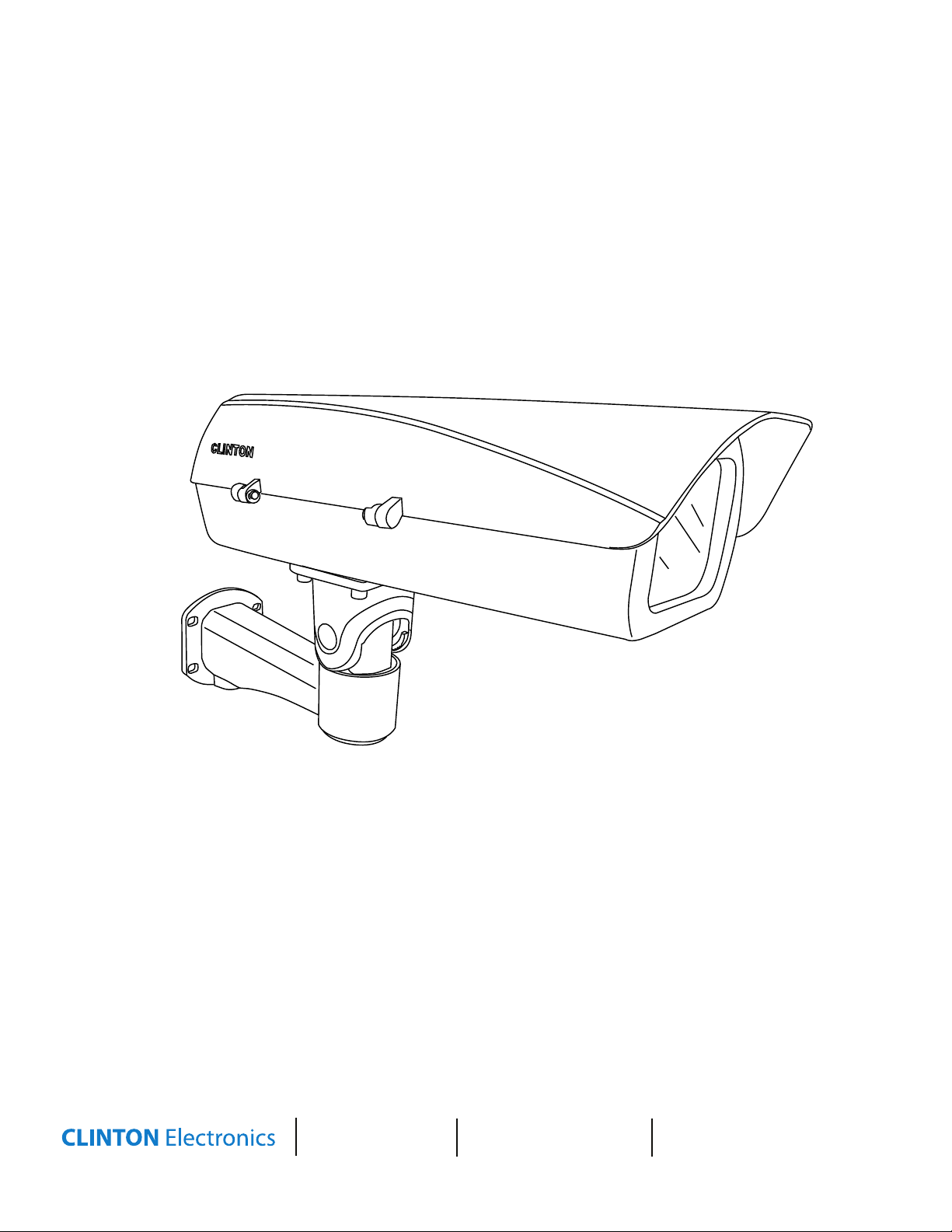
Outdoor Camera Housing
CE-H13
Installation Guide
CLINTON Electronics
6701 Clinton Road
Loves Park, IL 61111
1.800.447.3306 Sales
1.800.549.6393 Support
1.800.633.8712 Fax
www.clintonelectronics.com
Page 2
Cord route option 1:
back of arm
Cord route option 2:
bottom of arm
24V AC Jumper
to Camera
Included Items:
Plastic Adaptor
Plate Optional
Housing Case (qty. 1)
Mounting Arm (qty. 1)
5mm Allen Wrench (qty. 1)
Mounting Screws (1/4”-20 x 1.25”) (qty. 4)
Wall Anchors (qty. 4)
Camera Mounting Screw (1/4”-20 x 6mm) (qty. 1)
Camera Mounting Screw (1/4”-20 x 12mm) (qty. 1)
Washers (qty. 6)
Adaptor Plate (qty. 1)
Required Tools:
#2 Phillips Screwdriver
Drill with 10mm bit, or #2 Phillips bit
7mm drill bit
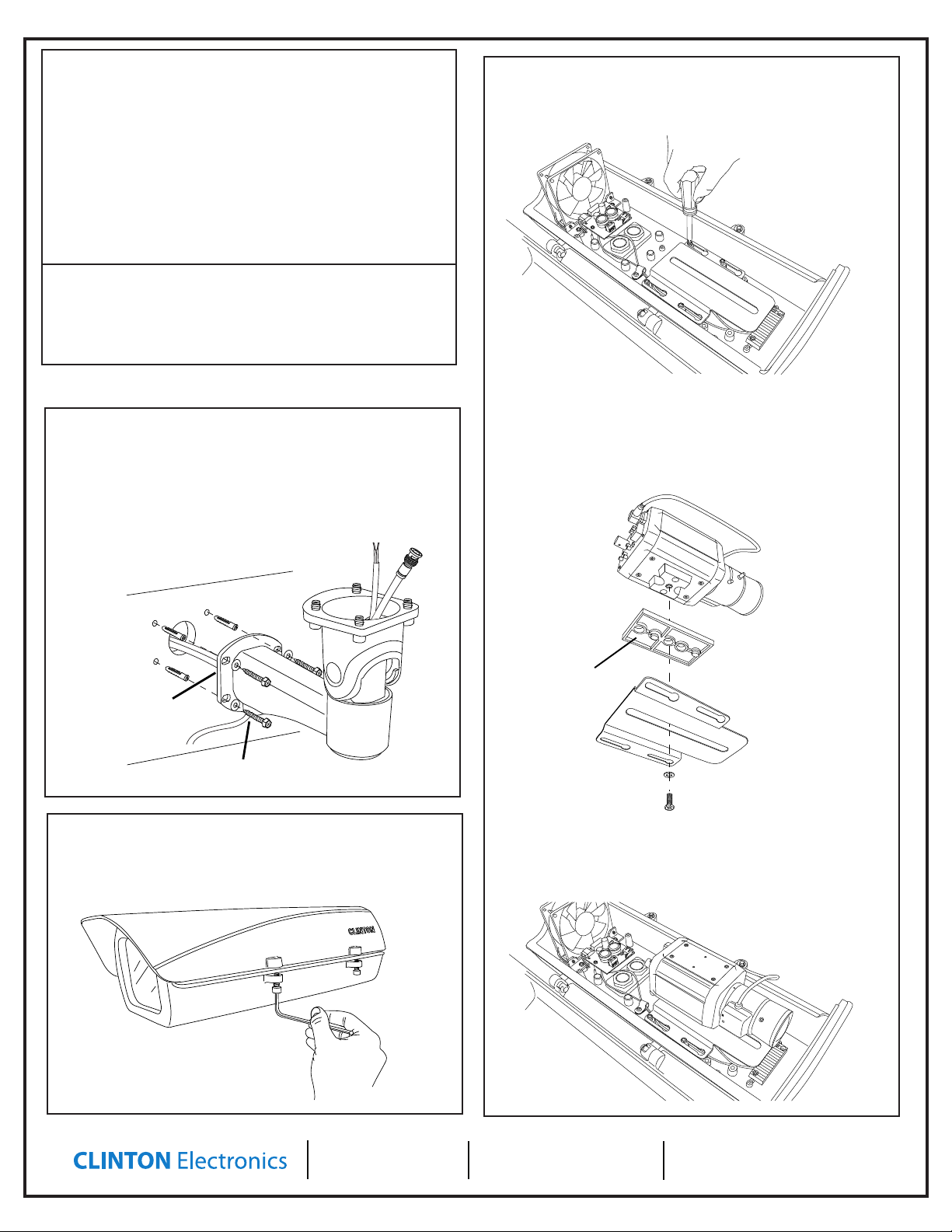
3. Attach Camera to Adjustable Plate
With a #2 Phillips screwdriver, remove the mounting plate that is
attached to the housing by loosening the 4 screws and sliding the
plate out.
Assembly Instructions
1. Attach Mount Arm
Feed the 24V/1A AC power, and a/v cables through the mounting
arm using one of the cord routing options shown below. Then use
the supplied screws, washers, and anchors as needed to secure
the arm to the building structure. (Use 7mm drill bit for anchors,
#2 Phillips bit or 10mm bit for screws)
Cord route option 1:
back of arm
Cord route option 2:
bottom of arm
2. Open Housing
Using the supplied allen wrench, loosen the two screws on the
side of the housing to open the case.
If needed, use the plastic adaptor plate to raise the camera up from
the bottom plate. Using this plate will also allow for smoother adjust-
ment of the camera later. If using the plate, mount camera using a
washer and the 1/4”-20 x 12mm screw. If not using the plastic adaptor
plate, mount camera using a washer and the 1/4”-20 x 6mm screw.
Replace the mounting plate with attached camera into the housing
by sliding it onto the screws. You may wish to leave it loose for later
adjustment of focus depth. If no adjustment is necessary, tighten the
screws to secure it in place.
CLINTON Electronics
6701 Clinton Road
Loves Park, IL 61111
1.800.447.3306 Sales
1.800.549.6393 Support
1.800.633.8712 Fax
www.clintonelectronics.com
Page 3
Assembly Instructions
IRIS JACK
OSD EXTRA
VIDEO OUT
POWER
VIDEO
DC
SET
BNC Input
24V AC Jumper
to Camera
24V AC Input to
Fan/Heater Board
Plastic Adaptor
Plate Optional
IRIS JACK
OSD EXTRA
VIDEO OUT
POWER
VIDEO
DC
SET
BNC Input
24V AC Jumper
to Camera
24V AC Input to
Fan/Heater Board
Gently pull upward from
base of housing & rotate
Secure housing lid & internal
camera when adjusting
Plastic Adaptor
Plate Optional
Loosen screw just
IRIS JACK
OSD EXTRA
VIDEO OUT
POWER
VIDEO
DC
SET
BNC Input
24V AC Jumper
to Camera
24V AC Input to
Fan/Heater Board
Plastic Adaptor
Plate Optional
enough to adjust
IRIS JACK
OSD EXTRA
VIDEO OUT
POWER
VIDEO
DC
SET
BNC Input
24V AC Jumper
to Camera
24V AC Input to
Fan/Heater Board
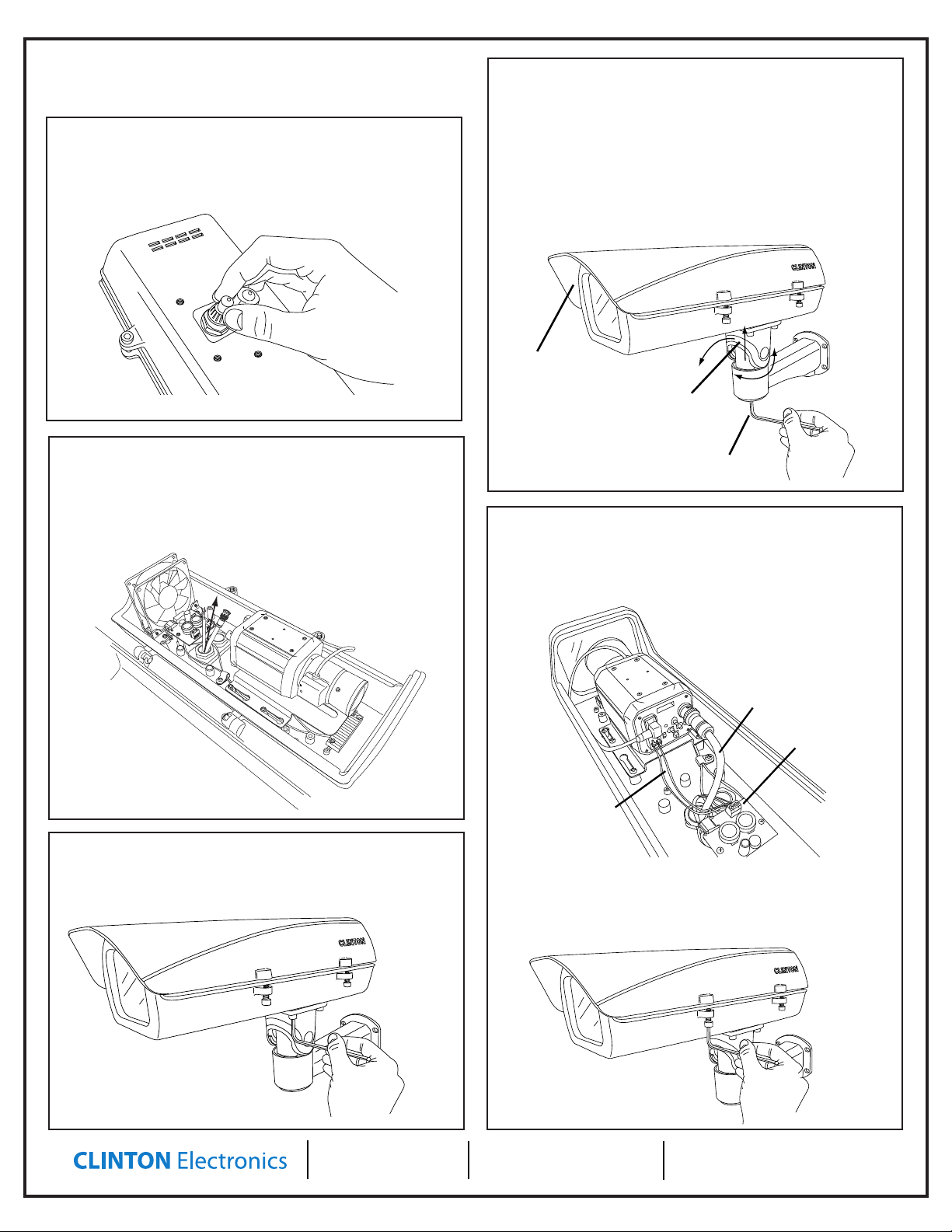
4. Prepare to route wires
Unscrew the cable nut to reveal a plastic nipple inserted in the
nut. Remove this piece and lightly screw on the cable nut to pre-
pare to feed the cables through the hole.
7. Adjust Angle
You can adjust the angle of the arm by loosening the single allen
screw located on the underside of the mount’s arm. Gently pull
upward on the base of the housing, and rotate. *NOTE: Loosen
screw just enough to move the housing into position. Loosen-
ing all the way will separate the arm from the housing. Adjust
the arm slowly to protect the housing lid from opening, or the
internal camera from harsh movements.
Secure housing lid & internal
camera when adjusting
Gently pull upward from
base of housing & rotate
5. Feed wires through hole
Feed the wires through the cable nuts on the bottom of the
camera, and pull as much slack as needed into the interior of the
camera housing. Tighten the cable nuts, then place the housing
on the arm to prepare for the next step.
6. Attach Housing to Arm
Attach the housing to the arm of the mount by tightening the
four allen screws located on the underside of the arm.
Loosen screw just
8. Complete setup
Make any nal electrical connections to the heater/fan board
and camera. Typical 24V/1A AC connection will run to the heater
board rst, then a jumper from the board to the camera.
Test and verify focus, zoom, and other parameters before closing
the case. Once complete, close the housing by tightening the two
allen screws that were loosened in Step 2.
CLINTON Electronics
6701 Clinton Road
Loves Park, IL 61111
1.800.447.3306 Sales
1.800.549.6393 Support
1.800.633.8712 Fax
www.clintonelectronics.com
Page 4

v.02.09.12
 Loading...