

Page 1
800-549-6393
800-633-8712
Page 2
Clinton Pro Series DVR
WARNING
RISK OF ELECTRIC SHOCK
DO NOT OPEN
WARNING: TO REDUCE THE RISK OF ELECTRIC SHOCK,
DO NOT REMOVE COVER (OR BACK).
NO USER-SERVICEABLE PARTS INSIDE.
REFER SERVICING TO QUALIFIED
SERVICE PERSONNEL.
The lightning flash with arrowhead symbol, within an equilateral triangle, is intended to alert the user to the presence of
uninsulated “dangerous voltage” within the product’s enclosure that may be of sufficient magnitude to constitute a risk of
electric shock.
The exclamation point within an equilateral triangle is intended to alert the user to the presence of important operating and
Maintenance (servicing) instructions in the literature accompanying the appliance.
COMPLIANCE NOTICE OF FCC:
THIS EQUIPMENT HAS BEEN TESTED AND FOUND TO COMPLY WITH THE LIMITS FOR A CLASS A DIGITAL
DEVICE, PURSUANT TO PART 15 OF THE FCC RULES. THESE LIMITS ARE DESIGNED TO PROVIDE
REASONABLE PROTECTION AGAINST HARMFUL INTERFERENCE WHEN THE EQUIPMENT IS OPERATED IN
A COMMERCIAL ENVIRONMENT. THIS EQUIPMENT GENERATES, USES, AND CAN RADIATE RADIO
FREQUENCY ENERGEY AND IF NOT INSTALLED AND USED IN ACCORDANCE WITH THE INSTRUCTION
MANUAL, MAY CAUSE HARMFUL INTERFERENCE TO RADIO COMMUNICATIONS. OPERATION OF THIS
EQUIPMENT IN A RESIDENTIAL AREA IS LIKELY TO CAUSE HARMFUL INTERFERENCE, IN WHICH CASE
USERS WILL BE REQUIRED TO CORRECT THE INTERFERENCE AT THEIR OWN EXPENSE.
CAUTION: CHANGES OR MODIFICATIONS NOT EXPRESSLY APPROVED BY THE PARTY RESPONSIBLE
FOR COMPLIANCE COULD VOID THE USER’S AUTHORITY TO OPERATE THE EQUIPMENT.
THIS CLASS OF DIGITAL APPARATUS MEETS ALL REQUIREMENTS OF THE CANADIAN INTERFERENCECAUSING EQUIPMENT REGULATIONS.
The information in this manual is believed to be accurate as of the date of publication. The information
contained herein is subject to change without notice. Revisions or new editions to this publication may be
issued to incorporate such changes.
Page 3

Important Safeguards
1. Read Instructions
All the safety and operating instructions should be read before the
appliance is operated.
2. Retain Instructions
The safety and operating instructions should be retained for future
reference.
3. Cleaning
Unplug this equipment from the wall outlet before cleaning it. Do not
Use liquid aerosol cleaners. Use a damp soft cloth for cleaning.
4. Attachments
Never add any attachments and/or equipment without the approval of
The manufacturer as such additions may result in the risk of fire,
electric shock or other personal injury.
5. Water and/or Moisture
Do not use this equipment near water or in contact with water.
6. Accessories
Do not place this equipment on an unstable cart, stand or table. The
equipment may fall, causing serious injury to a child or adult, and
serious damage to the equipment. Wall or shelf mounting should
follow the manufacturer’s instructions, and should use a mounting kit
approved by the manufacturer.
7. Power Sources
This equipment should be operated only from the type of power source
Indicated on the marking label. If you are not sure of the type of power,
please consult your equipment dealer or local power company.
8. Power Cords
Operator or installer must remove power and TNT connections before
handling the equipment.
9. Lightning
For added protection for this equipment during a lightning storm, or
when it is left unattended and unused for long periods of time, unplug it
from the wall outlet and disconnect the antenna or cable system. This
will prevent damage to the equipment due to lightning and power-line
surges.
10. Overloading
Do not overload wall outlets and extension cords as this can result in
the risk of fire or electric shock.
11. Objects and Liquids
Never push objects of any kind through openings of this equipment as
They may touch dangerous voltage points or short out parts that could
Result in a fire or electric shock. Never spill liquid of any kind on the
Equipment.
12. Servicing
Do not attempt to service this equipment yourself. Refer all servicing
to qualified service personnel.
13. Damage requiring Service
Unplug this equipment from the wall outlet and refer servicing to
qualified service personnel under the following conditions:
A. When the power-supply cord or the plug has been damaged.
B. If liquid is spilled, or objects have fallen into the equipment.
C. If the equipment has been exposed to rain or water.
D. If the equipment does not operate normally by following the
operating instructions, adjust only those controls that are covered by
the operating instructions as an improper adjustment of other
controls may result in damage and will often require extensive work
by a qualified technician to restore the equipment to its normal
operation.
E. If the equipment has been dropped, or the cabinet damaged.
F. When the equipment exhibits a distinct change in performance —
this indicates a need for service.
14. Replacement Parts
When replacement parts are required, be sure the service technician has
used replacement parts specified by the manufacturer or that have the
same characteristics as the original part. Unauthorized substitutions
may result in fire, electric shock or other hazards.
15. Safety Check
Upon completion of any service or repairs to this equipment, ask the
service technician to perform safety checks to determine that the
equipment is in proper operating condition.
16. Field Installation
This installation should be made by a qualified service person and
should conform to all local codes.
17. Correct Batteries
Warning: Risk of explosion if battery is replaced by an incorrect type.
Dispose of used batteries according to the instructions.
18. Tmra
A manufacturer’s maximum recommended ambient temperature
(Tmra) for the equipment must be specified so that the customer and
installer may determine a suitable maximum operating environment
for the equipment.
19. Elevated Operating Ambient Temperature
If installed in a closed or multi-unit rack assembly, the operating
ambient temperature of the rack environment may be greater than room
ambient. Therefore, consideration should be given to installing the
equipment in an environment compatible with the manufacturer’s
maximum rated ambient temperature (Tmra).
20. Reduced Air Flow
Installation of the equipment in the rack should be such that the amount
of airflow required for safe operation of the equipment is not
compromised.
21. Mechanical Loading
Mounting of the equipment in the rack should be such that a hazardous
condition is not caused by uneven mechanical loading.
22. Circuit Overloading
Consideration should be given to connection of the equipment to
supply circuit and the effect that overloading of circuits might have on
over current protection and supply wiring. Appropriate consideration
of equipment nameplate ratings should be used when addressing this
concern.
23. Reliable Grounding
Reliable grounding of rack mounted equipment should be maintained.
Particular attention should be given to supply connections other than
direct connections to the branch circuit (e.g., use of power strips).
Page 4

Table of Contents
Chapter 1 Basic Install Page 7
1.1 Connecting the Video Source
1.2 Connecting the Monitor
1.3 Connecting the Mouse
1.4 Connecting the Network Port
1.5 Connecting the Power
Chapter 2 Programming the DVR Page 9
2.1 Pro Series Tool Bar
2.2 Logging into the system
2.3 The Menu Tab
2.3.1 System Setup Icon
2.3.1.2 General Setup
2.3.1.3 Alarm Type Setup
2.3.1.4 Hard Drive Setup
2.3.1.5 Password Setup
2.3.1.6 Configuration Saving
2.3.1.7 Shutdown
2.3.2 Camera Setup Icon
2.3.2.2 Camera Setup
2.3.2.3 Adjusting Picture Quality
2.3.2.4 PTZ Setup
2.3.2.5 Spot Monitor Setup
2.3.2.6 Sequential Switching
2.3.2.7 Monitor Setup
2.3.3 Network Setup
2.3.3.2 Ethernet Setup
2.3.3.3 Remote Client Setup
2.3.3.4 Email Setup
Chapter 3 Recording Video Page 32
3.1 Recording Schedule
3.2 Time Recording
3.2.1 Programming All The Cameras at once
3.2.2 Programming Individual Cameras
Page 5

Table of Contents (Cont.)
3.3 Event Programming
3.3.1 Programming All the Cameras at once
3.3.2 Programming cameras individually
3.3.3 Programming the Motion Fields
3.4 Checking the DVR Status
Chapter 4 Watching Live Video Page 41
4.1 Camera Change Sub-Menu
4.2 PTZ Control
Chapter 5 Playing Back Recorded Video Page 45
5.1 Searching Video
5.1.1 Time and Date Search
5.1.2 Event Search
5.2 Playback Controls
5.3 Multi-Screen Hot Button
Chapter 6 Archiving Video Page 49
6.1 Backup
6.2 Cut and Save
6.3 Playing back archived video on your PC
Chapter 7 Advanced Installation Page 52
7.1 Connecting Audio
7.2 Connecting Alarms
7.3 Connecting the RS485
7.4 Connecting the PTZ
Appendix – Troubleshooting Page 55
Appendix – Specifications Page 56
Page 6
Clinton Pro Series DVR
Introduction
Features
The Clinton Pro Series digital video recorder (DVR) provides recording capabilities for four, eight or 16
camera inputs. It provides exceptional picture quality in both live and playback modes, and offers the
following features:
• 4, 8 or 16 Composite Input Connectors
• Compatible with Color (NTSC or PAL) and B&W (CCIR and EIA-170) Video Sources
• Multiple Search Engines (Date/Time, Calendar, Event)
• Records up to 240 NTSC Frames per Second (200 PAL Frames per Second)
• “Loop-Through” Video Connectors
• Continuous Recording in Disk Overwrite Mode
• Continues Recording while Archiving, Transmitting to Remote Site and during Playback
• User-friendly Graphical User Interface (GUI) Menu System
• Various Recording Modes ( Manual / Schedule / Event)
• Audio Recording and Playback
• Alarm Connections Include: Input, Output.
• Built-in Alarm Buzzer
• Live or Recorded Video Access via Ethernet.
3
Page 7
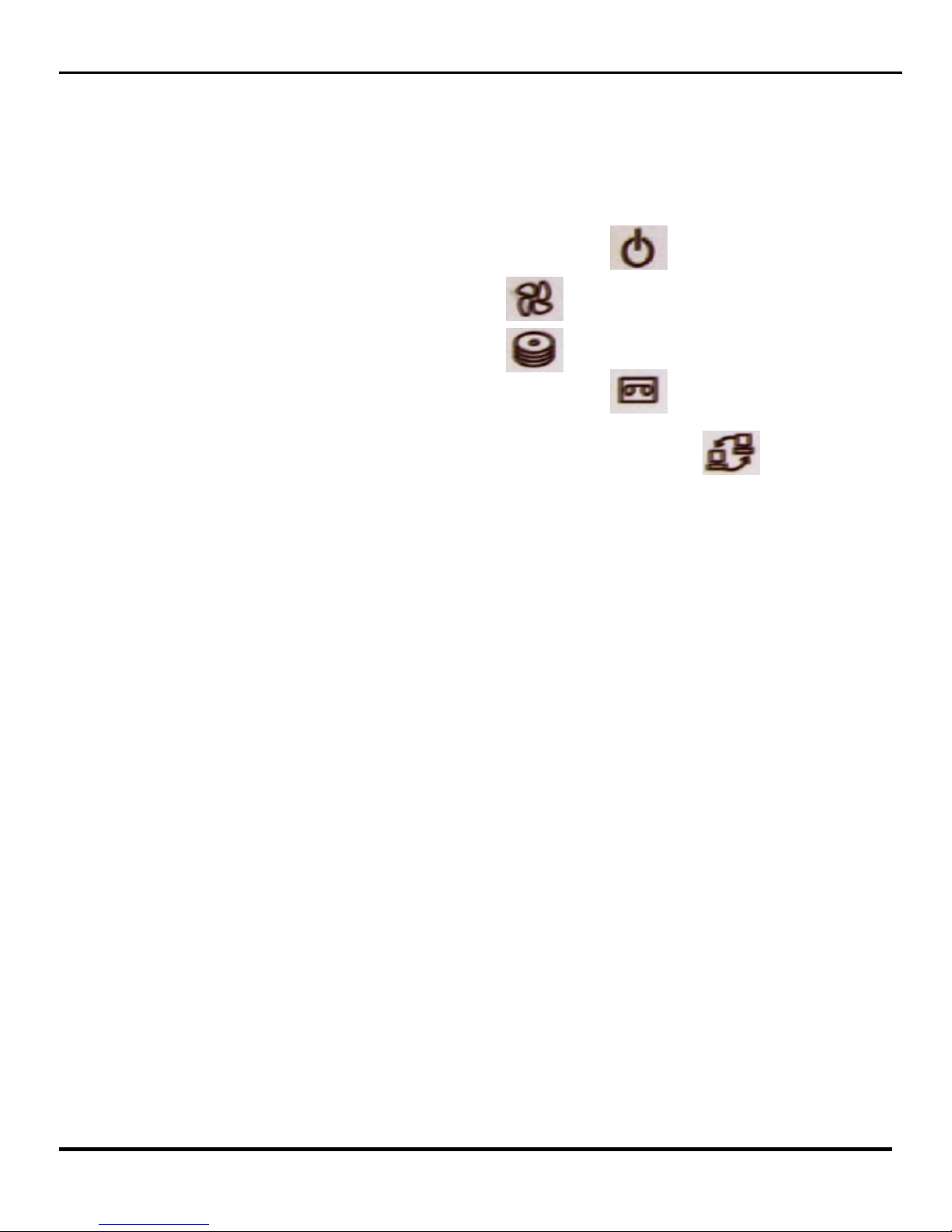
Front Panel Description
The front panel of the Pro Series DVR features two USB Ports, The CDRW, and Five LED
Indicators which are explained below.
Power Led is lit when power is provided to the DVR Unit.
Fan Led is lit when the cooling fan is running.
The CDRW Led is lit when the CDRW is in use.
The Record Led is lit when the DVR unit is recording.
The Network LED is let when the DVR unit is connected to a network.
4
Clinton Pro Series DVR
Page 8
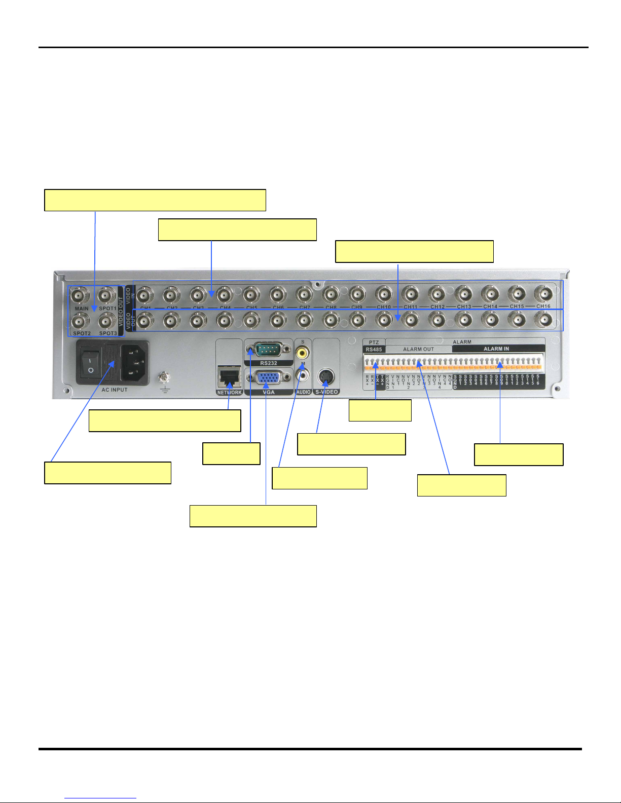
Rear Panel Layout
CAMERA INPUT (1~16)
LOOP OUT (1~16)
MONITOR OUTPUT (MAIN / SPOTS)
AC POWER INPUT
RJ45 ETHERNET PORT
RS232
VGA MONITOR OUT
S-VIDEO OUT
AUDIO IN/OUT
RS485
ALARM OUT
ALARM IN
5
Clinton Pro Series DVR
Page 9
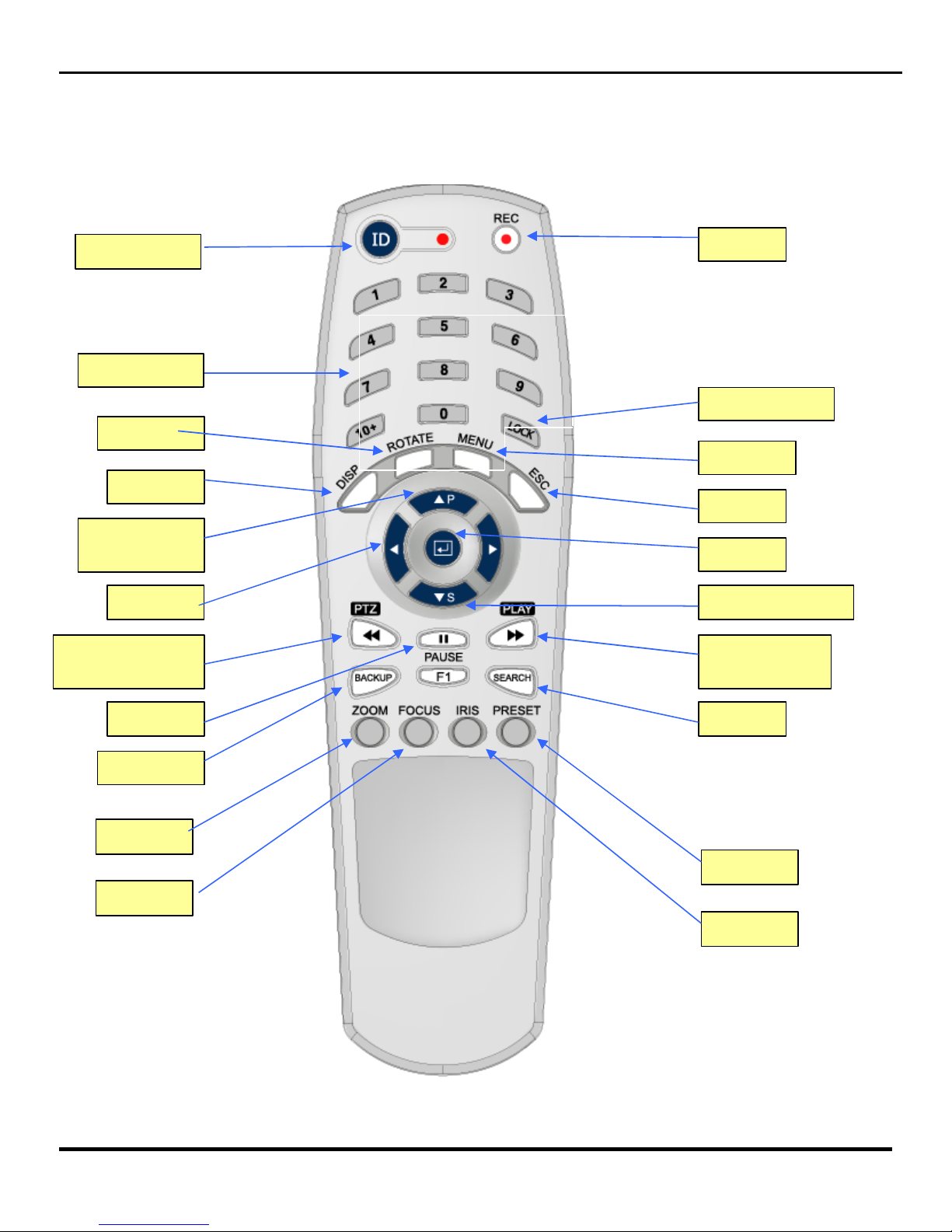
IR Remote Controller
Number
Lock (Log out)
Fast Rewind /
PTZ
Fast Forward
/ Play
▲ Arrow /
Panorama
Menu
Search
Backup
Rotate
Pause
Display
Escape
ID
REC
◀ Arrow ▼ Arrow / Smart
Zoom
Focus
Iris
Preset
Enter
6
Clinton Pro Series DVR
Page 10
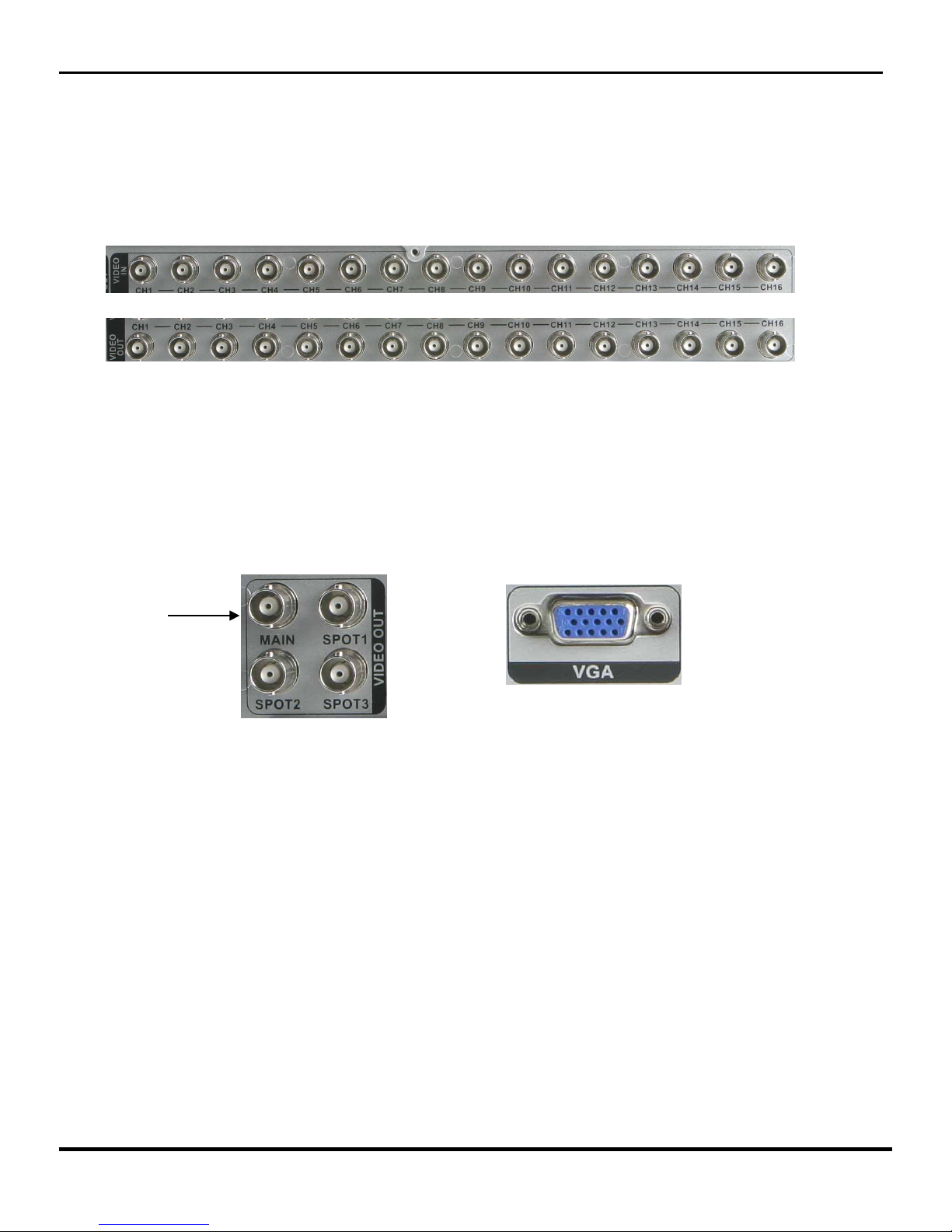
1.1 Connecting the Video Source
Connect the coaxial cables from the video sources to the BNC Video In (Top Row) connectors.
If you would like to connect your video source to another device, you can use the Loop BNC
connectors (Bottom Row).
NOTE: The Loop BNC connectors are auto terminated. Do NOT connect a cable to the Loop BNC
unless it is connected to another terminated device because it will cause poor quality video.
1.2 Connecting the Monitor
Connect the monitor to either the Main BNC Connection or the VGA connection located on the
back panel of the DVR Unit.
1.3 Connecting the Mouse
Connect the mouse to the first (left) USB slot located on the DVR’s front panel.
NOTE: The Pro Series DVR will work with either the enclosed IR Remote or the Mouse.
Clinton Pro Series DVR
Chapter 1 – Basic Installation (Physical Connections)
Main
7
Page 11

1.4 Connecting to the Network Port
The DVR can be networked using the 10/100Mb Ethernet connector. Connect a Cat5 cable with
an RJ-45 jack (Standard Ethernet Cable) to the DVR connector. The DVR can be networked
with a computer for remote monitoring, searching, configuration and software upgrades. See
Chapter 4 — Configuration for configuring the Ethernet connections.
1.5 Connecting the Power
Attach the supplied power cord into the back of the DVR unit, then connect the other end of the
cord into an electrical outlet to supply the DVR with power.
Once all of the physical connections have been made, your DVR will be initialized and it will
take approximately 60 seconds. As soon as the DVR completes its initialization process, it will
begin showing live video on the attached monitor (assuming power has been applied to the
connected cameras). The default mode will display all cameras at once.
Once the Initialization process has finished the DVR is ready for programming.
NET
Clinton Pro Series DVR
8
Page 12
Clinton Pro Series DVR
Chapter 2 — Programming the DVR
2.1 The Pro Series Tool Bar
The Pro Series DVR’s main tool bar (pictured below) will appear when you move the mouse
cursor near the top of the Live Video Screen on the main monitor. All programming, video
searching and archiving features can be accessed through this tool bar.
Tool Bar (Pictured above).
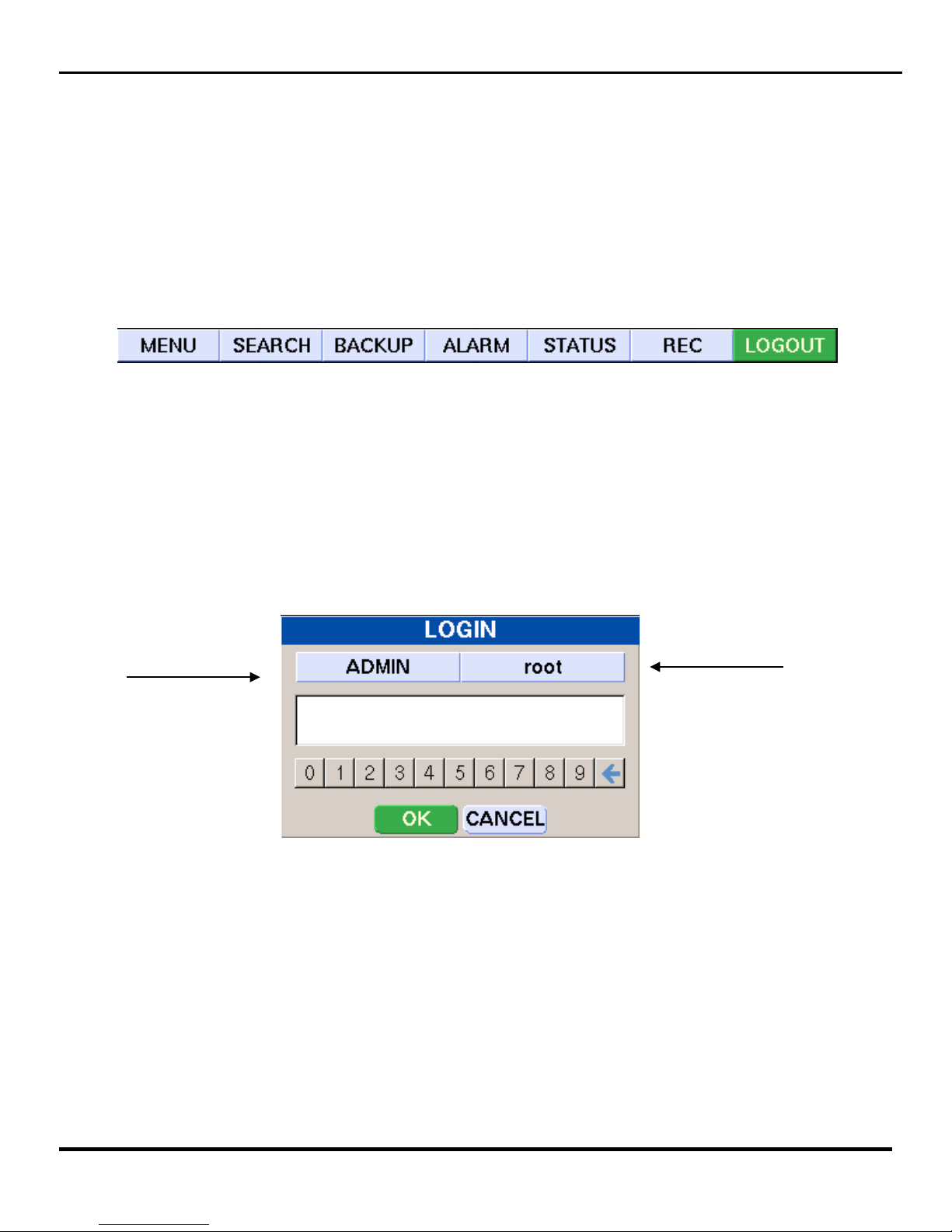
2.2 Logging into the System
Prior to gaining access to any of the Pro Series DVR’s features or functions, you will need to login
to the DVR. Prior to logging into the DVR, using the mouse, drag the cursor over the menu tab on
the DVR tool bar and left click. The Login Screen will appear on the monitor (below).
Security Level Button Password Button
Using the Mouse, click on the security level button until it reads ADMIN. During initial setup the
Password Button should read root. Then click on the numbers listed below to enter the Passcode.
The Default Pass code is 1111. Then click on OK and you will be logged into the DVR.
Keep in mind, there are three levels of security for the Pro Series DVR, Admin, Superuser and
User. Only users logged-in under the Admin security level are allowed to make programming
changes to the DVR. We highly recommend safeguarding the default Password and entering your
own passwords and passcodes under the appropriate security levels. See Section 2.3.1.5 for more
information on setting passwords.
9
Page 13
Clinton Pro Series DVR
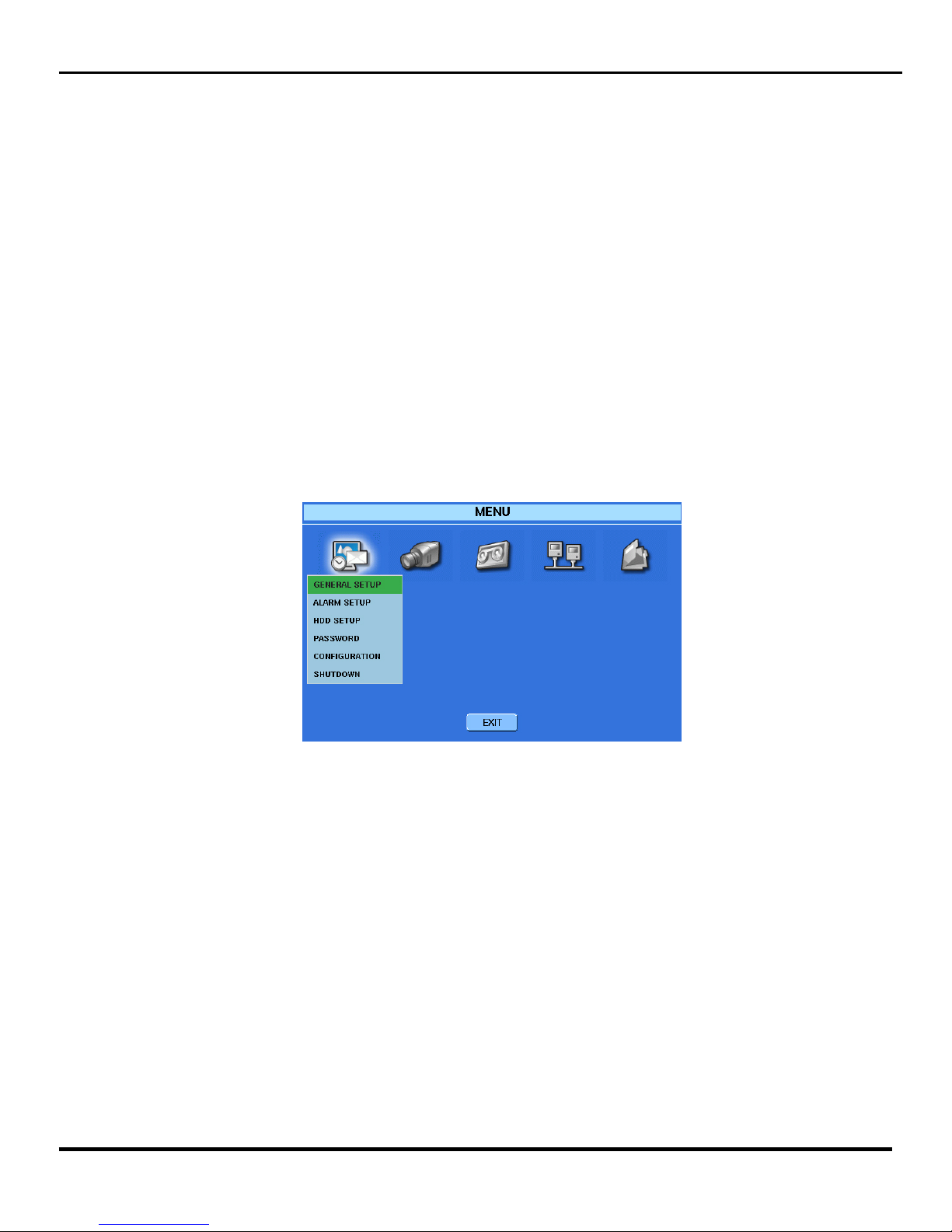
2.3 The Menu Tab
All initial programming is done through the menu tab on the DVR Toolbar. Click on the Menu Tab
and the Setup Menu (Pictured Below) will appear. There are five submenus available through the
Setup Menu. Click on each icon to access each submenu. The icons (from left to right below) are 1.
The System Setup Icon, 2. Camera Setup Icon, 3. Recording Setup Icon, 4. Network Setup Icon, 5.
System Information Icon.
The Setup Menu
10
Page 14
Clinton Pro Series DVR
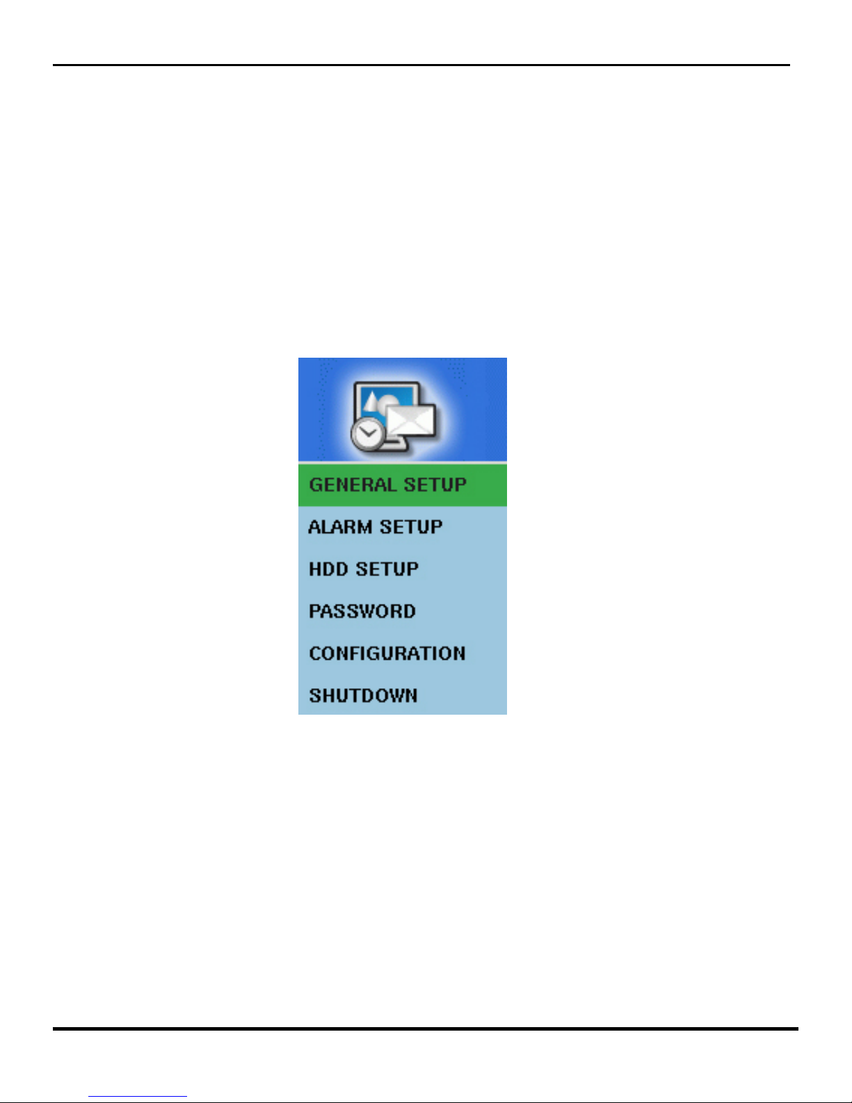
2.3.1 The System Setup Icon
By clicking on the System Setup Icon located in the main menu a drop down box (Pictured Below) will
appear on the monitor. The submenu’s listed under this icon will allow you to do the basic system
programming for the Pro Series DVR.
11
Page 15
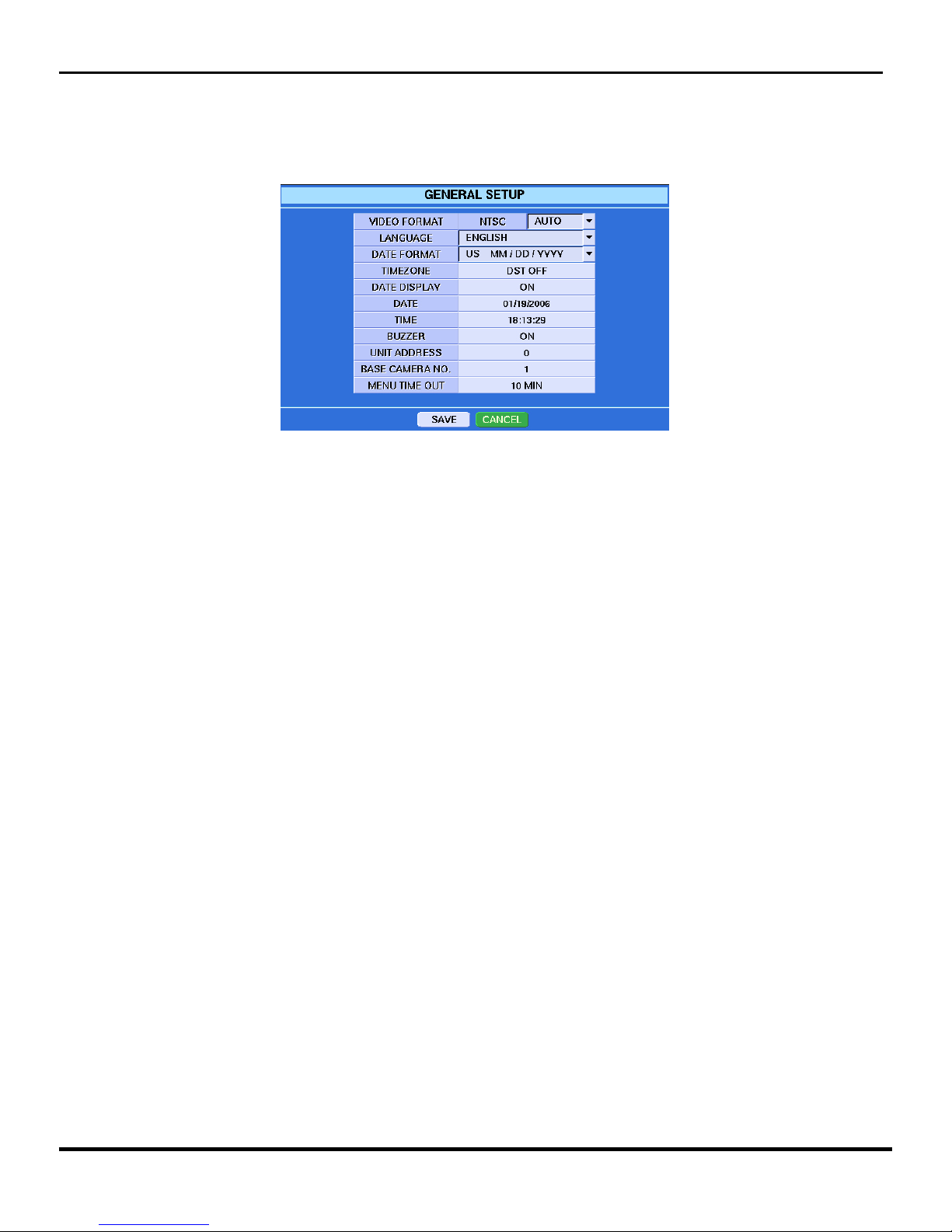
2.3.1.2 General Setup
Click the General Setup listing and the General Setup Sub-Menu will appear.
VIDEO FORMAT: For North American operation should be NTSC or AUTO.
LANGUAGE: Is defaulted to English.
DATE FORMAT: Allows you to change the way the date will appear on the monitor.
TIMEZONE: Clicking on the Time zone category will open a dropdown box where you can
choose between several DST (Daylight Savings Time) locations or choose to not use the DST
function at all. If you choose DST OFF, the DVR will need to be manually programmed each and
every time there is a time change.
DATE DISPLAY: When On, the Date will be displayed in Live View for each camera. When off,
no date will be displayed in Live View.
DATE: Allows you to make changes to today’s date.
TIME: Allows you to make changes to the time.
BUZZER: There are several audible warning sounds available on the Pro Series DVR. This is the
main on/off switch for all buzzers. When off is chosen, you will not be able to select any of the
individual warning buzzers located throughout the programming menus.
UNIT ADDRESS: You can set up an ID for your DVR to distinguish the unit when using
multiple DVR’s.
BASE CAMERA NUMBER: Useful in multiple DVR situations. Default is 1, but you can assign
any starting point.
MENU TIME OUT: You can set up the menu time-out duration up to 10 minutes.
NOTE: Any changes made in this sub-menu, you must click on the SAVE button located at
the bottom of the General Setup Submenu.
Clinton Pro Series DVR
12
Page 16

2.3.1.3 ALARM TYPE Setup
Select the ALARM TYPE from the System Setup sub-menu and the ALARM TYPE sub-menu will appear.
Drop Down Arrow
Alarm IN Alarm OUT
ALARM IN: Click on the Alarm In selection (pictured above) to program the polarity of the alarm
inputs connected to the DVR. Use the Drop Down Box (pictured above) to select NO (Normally
Open) or NC (Normally Closed). The Pro Series DVR has one available alarm input for each
camera on the system.
ALARM OUT: Click on the Alarm Out selection (pictured above) to enable or disable each alarm
output connected to the DVR. The Alarm Set Button will activate any connected alarms, the
Alarm Clear Button will clear all triggered alarms. The Pro Series DVR has four alarm outputs, no
matter how many camera inputs each model may have.
NOTE: Be sure to click on the SAVE button at the bottom of the ALARM TYPE sub-menu to
finalize any changes made in this sub-menu.
2.3.1.4 Hard Drive Setup
All HDD functions are done at the factory. Contact your service representative for more
information.
Clinton Pro Series DVR
13
Page 17
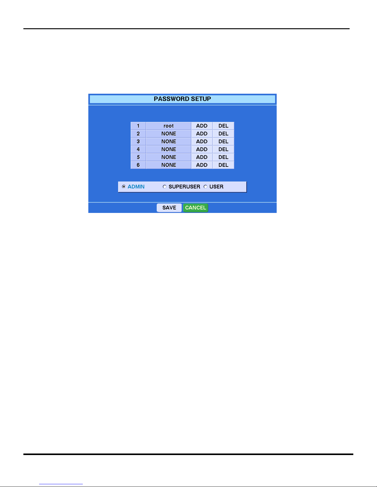
2.3.1.5 PASSWORD SETUP
To add or delete passwords to the head end of the Clinton Pro Series DVR, select the Password
selection from the System Setup sub-menu, and the following menu will appear on the monitor.
There are three levels of security built into the Clinton Pro Series DVR: ADMIN, SUPERUSER
and USER. Passwords can only by added, deleted or changed by and ADMIN level user.
To ADD a new password, click on the selected security level you would like to add and then click
on the ADD button next to an open user spot. An open user spot will say NONE in the name
column. A keyboard will appear on screen. Type in a user name and then hit the SAVE button on
the keyboard. A new menu will appear asking you for a new password. The new password must be
at least 4 numbers. The DVR will ask you to confirm the new password, then click the SAVE
Button and your new password will be added.
To DELETE a password, click on the selected security level and then on the DEL button next to
user you would like to delete. The system will ask you to confirm your deletion. Click yes, then
click SAVE at the bottom of the Password sub-menu.
CAUTION: Do not delete the default Admin account (root) before adding a new account.
ADMIN Level has access to all on board features of the DVR
SUPERUSER Level can access al features except program changes
USER Level can watch live video, use the PTZ functions, and check the DVR status.
Clinton Pro Series DVR
14
Page 18
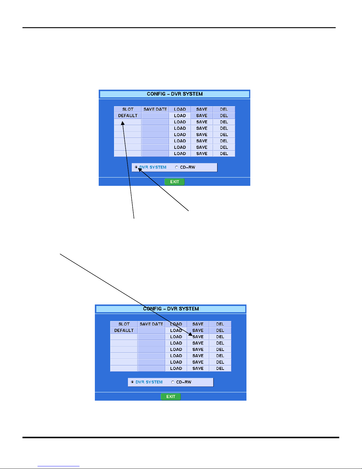
2.3.1.6 CONFIG
You can save configurations of the Clinton Pro Series DVR’s programming to the DVR or a CD. This would
be helpful in programming multiple DVR’s with the exact same programming. Select the CONFIG submenu from the System Setup sub-menu and the following screen will appear.
To Save a configuration to the DVR: Click on the DVR System button located at the bottom of the menu.
Then click on a blank box under the SLOT column and a virtual keyboard will appear. Give your
configuration a name and click on the keyboard’s SAVE button.
The current configuration now has a name and is ready to be saved to an archiving portion of the hard
drive. Click SAVE on the line next to your newly named configuration and the configuration will be saved.
Once saved, the date will appear next to your configuration name.
Now you can make changes to the programming of your DVR and always revert back to any saved
configuration.
Clinton Pro Series DVR
15
Page 19

To LOAD a configuration saved on the DVR, select the CONFIG submenu from the System Setup
Submenu. Click LOAD on any one of the saved configurations and the following screen will appear.
You can now choose to load the entire configuration or, using the mouse place a check next to the items
you want to load and then click on OK. The DVR will ask you to confirm your choice, click OK and the
saved configuration will be loaded within a few seconds.
SAVE/LOAD CONFIGURATION TO A CD
Select the CONFIG submenu from the System Setup submenu and the following will appear on the main
monitor.
Click on the CD-RW Button and the CD LOAD/SAVE Menu will appear. (Pictured on next page)
Clinton Pro Series DVR
16
Page 20

Make sure the configuration you want to save to the CD is the active configuration on the DVR. Place a CD
in the CD drawer of the DVR and click the SAVE button. Within a few seconds the CD Drawer will reopen
and the configuration will be saved to that CD. You can now place that CD in any Pro Series DVR and
download the configuration.
TO LOAD a saved configuration onto a second DVR, put the CD with the saved configuration in the CD
drawer of the DVR you are attempting to configure and click on the LOAD button of the menu pictured
above.
Clinton Pro Series DVR
17
Page 21

2.3.1.7 SHUTDOWN
You can restart or shutdown your DVR by clicking on the SHUTDOWN selection in the System Setup
submenu. The following screen will appear.
Select RESTART or SHUTDOWN and then click OK.
Clinton Pro Series DVR
18
Page 22

Clinton Pro Series DVR
2.3.2 The Camera Setup Icon
By clicking on the Camera Setup Icon, a dropdown menu (pictured below) will appear. By selecting
the appropriate category in this dropdown box, authorized users can program and adjust connected
cameras, including PTZ cameras.
19
Page 23

Clinton Pro Series DVR
2.3.2.2 The Camera Setup Menu: Setup
By clicking on the Setup Line under the Camera Setup Icon, the Setup Menu (Pictured Below) will
appear.
1. Clicking on the Camera Label Drop Box (Pictured Below) will allow you the following
three options.
•
ALL – Displays the camera name and camera number for each camera in the live
display.
•
NUMBER – Displays just the camera number for each camera in the live display.
•
OFF – Will display no camera headings in the live display.
•
You must click the SAVE button at the bottom of the Sub-Menu to save all
changes.
Camera Label Drop Box
2. To name each camera on the DVR, click on each camera under the NAME column of
the Camera Setup Menu. A keyboard (Pictured Below) will appear on the monitor.
Type in the name you want for the corresponding camera and click on the SAVE
button on the virtual keyboard. Repeat this process for all cameras you wish to
rename. NOTE: After changing all of the camera names, you must click on the
SAVE button at the bottom of the Camera Setup Submenu to make the changes
final.
20
Page 24

Clinton Pro Series DVR
3. By clicking on the INSTALL+ button in this submenu you will either turn each camera
on or off. If the Camera is ON, each camera will record and show live video. If any camera
is off in this menu it will not record or show live images. You can control all of the
cameras in this submenu by clicking on the INSTALL+ button or you can control each
camera individually by clicking on each corresponding camera in the INSTALL+ Column.
4. The HIDDEN+ button in the Submenu, controls the live display only. If the cameras
under the HIDDEN+ column are off, they will still record, but they will not display any live
images. Changes in the column are made the same way they are made in the INSTALL+
column.
NOTE: To finalize any programming changes in the Camera Setup Submenu, you must click
on the SAVE button at the bottom of the Submenu.
Save Button INSTALL+ Column
HIDDEN+ Column
21
Page 25

2.3.2.3 Camera Setup Menu: Adjusting Picture Quality
By clicking on the Adjustment Line under the Camera Setup Icon, the Adjustment Menu (Pictured
Below) will appear.
At the top of the Adjustment Submenu is the LIVE+ Button. You need to adjust the picture quality
for both the Live Display and how you want the recorded image to look. If the Top button reads
LIVE+, any changes you make in this submenu will only affect the live display. Click on the
LIVE+ button to change it to the RECORD+ button. Now you can adjust how you want the
recorded video to appear.
EXAMPLE: If you have the picture quality in Live and Record set to the same settings, it is
possible that the compression process could lighten or darken your recorded image. This feature
allows you to adjust for those instances.
Change cameras by clicking on the arrows next to the camera number button.
Change quality issues by clicking on the numeric value listed next to the quality issue you wish to
change: Bright, Contrast, Saturation, or Hue. After clicking on each category, a slide bar will
appear on the monitor. Use your mouse to control the slidebar and click the save button under the
slidebar to save your changes.
Click on the arrows under the Position Heading to adjust camera placement on the monitor.
You can also change the picture quality values on any one camera and have those changes affect
all of the systems cameras by clicking on the APPLY ALL button.
NOTE: To finalize any programming changes in the Camera Adjustment Submenu, you
must click on the SAVE button at the bottom of the Submenu.
LIVE+ Camera Number
Clinton Pro Series DVR
22
Page 26

2.3.2.4 Camera Setup Icon: PTZ Setup
In this sub-menu, authorized users can program the DVR to control PTZ cameras connected to the
DVR.
By clicking on the PTZ Setup Line under the Camera Setup Icon, the PTZ Setup Menu (Pictured
Below) will appear.
Clicking on the PORT+ Column will allow users to program the Baud Rate, Data Bit, Parity and
Stop Bit values for each PTZ. This is all information that will be supplied by the PTZ
manufacturer.
Clicking on the ID+ Column will allow users to change the ID for each PTZ connected to the
DVR.
Clicking on the TYPE+ Column will allow users to change the PTZ protocol for each PTZ
connected to the DVR.
NOTE: PTZ’s need to be connected to the RS485 terminal on the back of the DVR following
the camera manufacturer’s instructions. More information on the physical connection of
PTZ’s is listed in Chapter 7 of this manual.
NOTE: Due to the proprietary nature of PTZ’s not all PTZ’s will have full functionality
when connected to the Pro Series DVR.
Clinton Pro Series DVR
23
Page 27

2.3.2.5 SPOT SETUP
Your DVR can set up 3 spot monitors and assign cameras to each spot. Click on the SPOT SETUP in the
System Setup Menu and the following SPOT SETUP screen will appear.
SPOT SETUP. SPOT SETUP(2).
SEQUENCE+: Turns the sequential switcher for each spot monitor On or Off. You can control this feature
for all cameras at once by clicking on the SEQUENCE+ button, or for each spot monitor individually by
clicking the word On or Off under the SEQUENCE+ column for each camera. If you choose the Off function
for this feature, all of the cameras you assign to this spot monitor will appear simultaneously.
POPUP+: When you turn on the Popup feature for the spot monitors, anytime an assigned camera has an
event it will override the sequence and “Popup” on the spot monitor.
CAMERA+: Clicking on any space under the CAMERA+ column will allow you to assign cameras to that
corresponding spot monitor. Simply use the mouse to put a checkmark next to the cameras you want to
display on that particular spot monitor.
INTERVAL+: If you choose to utilize the SEQUENCE+ feature, you can program how long each camera will
dwell or wait before it changes to the next camera by clicking on the three areas located under the
INTERVAL+ button.
NOTE: Same cameras can’t be shown on the spot monitors at the same time. When selecting
ROTATE-ON and all cameras for all of 3 spots, the spot 1 will display camera number 1, spot 2 –
camera number 2 and spot 3 – camera number 3. When selecting SEQUENCE – ON, all cameras for
all of 3 spots, there will be time interval in rotating the cameras.
Clinton Pro Series DVR
24
Page 28

2.3.2.6 SEQUENCE (Sequential Switching)
To set the dwell time for the sequential switching of cameras on the main monitor live display,
select the SEQUENCE sub-menu in the Camera Setup Setup sub-menu and the following screen
will appear.
Slide Bar
PAGE DWELL TIME: Is for sequencing an entire page of cameras in the quad and 9-camera
display mode.
CAMEO DWELL TIME: By clicking on the time listed next to this button, a slide bar will appear
(above right) and allow you to program the dwell time for each camera during sequential
switching.
NOTE: Remember to click on the SAVE button at the bottom of the sub-menu to finalize
any program changes in the SCREEN ROTATE submenu.
Clinton Pro Series DVR
25
Page 29

2.3.2.7 MONITOR SETUP
Select the MONITOR SETUP sub-menu in the Camera Setup sub-menu and the following screen
will appear.
BORDER COLOR: You can change the color of the border lines which separate cameras on the
multiple camera display screen in the live mode. Click on the Border Color selection and choose
your new color.
ALPHA BENDING: You can adjust the transparency of the menu screen by clicking on the box
beside ALPHA BLENDING and using the slide bar.
SCREEN POSITION: Click on the arrows to adjust the screen position on the main monitor.This
feature will move everything on the screen.
Clinton Pro Series DVR
26
Page 30

Clinton Pro Series DVR
2.3.3.2 Ethernet Setup
Click on the Ethernet Setup button and the Ethernet Setup submenu (below) will appear. If the
network you are attempting to access utilizes a Dynamic IP configuration, simply click the button
next to the Dynamic IP Label to ON, then click on the Save button at the bottom of the submenu.
Dynamic IP
ON or OFF
2.3.3 Network Setup
Click on the Network Setup Icon in the Menu Tab and the Network Submenu will appear.
27
Page 31

If the network you are attempting to access uses a Static IP scheme, click the Dynamic IP to OFF and then
click on the green arrow next to the IP Address (Below) to enter the appropriate network information. Using
the mouse, place the cursor next to the subject you want to change and then click to access the virtual
keyboard. Once you have entered the appropriate network information click the save button on the bottom
of the submenu.
NOTE: It is highly recommended to have the end-users IT Manager available when programming
this unit to a network.
NOTE: You must complete the instructions in 2.3.3.3 to successfully finish programming the DVR
for network communication
2.3.3.3 Client Setup
There are three steps to the Client Setup (Remote Networking) process. In the Network Setup Submenu,
click on the Client Setup selection and the following menu will appear.
Clinton Pro Series DVR
28
Page 32

Again, there are three steps to programming the Client Setup feature on the DVR, the Connection, the
remote User Account and the IP Access Range. To program each of these functions, select the
appropriate menu from the bottom of the Client Setup Submenu. (Below)
Connect User Account IP Access Range
The Connect Submenu, is for entering the TCP Port Number (Static Open Port on Customer’s Firewall).
The default TCP port is 7000. Click on the default, and the virtual keyboard will appear. Enter the new
information.
The User Account Submenu (Below) is for entering the passwords or security levels of each remote user
authorized to access the DVR through the remote software. There are two levels of remote users. The
Admin level can access the DVR’s programming, recorded and live video. The User level can only access
recorded and live video. You can authorize new remote users by highlighting the level you would like to
assign and then click the ADD button next to a NONE button. Type the new account by using the virtual
keyboard. When saving a new account, the password screen will appear. Type the password for the new
account. The confirm screen will appear. Retype the password. Click on the Save button at the bottom of
the submenu to save all changes.
Clinton Pro Series DVR
29
Page 33

Your customer can also limit the range of IP Addresses available to the DVR. Click on the Access Range
feature in the Client Setup Submenu and the following screen will appear.
Click on a blank IP Address to enter changes. When using this feature, if the IP address programmed in
the Ethernet Setup portion of this manual does not fall in the range programmed above, a remote
connection will not be possible. The default range is ALL and it will allow any IP address to access to the
DVR.
NOTE: Make sure to click on the Save button at the bottom of the Sub Menu to save any changes.
2.3.3.4 E-MAIL SETUP
Click on the E-Mail Setup selection in the Network Setup SubMenu and the following screen will
appear.
Clinton Pro Series DVR
30
Page 34

The PRO Series DVR can send e-mail notifications to up to six different e-mail addresses, for any or all of
the following events. 1. Motion Events, 2. Alarm Events, 3. Video Loss, 4. Power Outages, 5. Menu Hits, 6.
Login Fail, 7. Disk Full, 8. Login.
Click on one of the SET tabs located under the SEND+ Tab and the following Pop Up menu will allow you
to select which events you would like to set up for E-Mail notification.
Click on one of the tabs located under the CAM+ Tab and the following Pop Up menu will allow you to
program events for email by individual camera.
The Retry button allows you to select how many times the DVR will attempt to resend an e-mail should the
original transmission get rejected.
Click the PIC+ Tab to on and the DVR will attach a still-frame image with each e-mail associated with
Motion and Alarm Events.
Click on the space under the E-Mail Address to enter the desired e-mail address you want each message
sent to.
NOTE: The e-mail function will not work unless the DNS Server information is properly
programmed in the Network Setup Process.
Clinton Pro Series DVR
31
Page 35

Recording Video
Once you have installed the DVR following the instructions in Chapter 2 – Basic Installation, it is ready to
record. Unless you change the setup, the DVR will start recording when you press the REC button on the
remote or click on the REC button on the Main Toolbar.
Although you will be able to record without changing the unit from its original factory settings, you will want
to take advantage of the DVR’s many tools.
Once recording has started, each camera on the live display will display the corresponding recording
information as described below, depending on how you program the unit.
Clinton Pro Series DVR
Chapter 3 -- Recording Video
Recording Camera Window
TMAV
01 C0
REC
01 C0
T : Time Recording
M : Motion Recording
A : Alarm Recording
V : Videoloss Recording
REC: Default Recording
32
Page 36

Click on the Recording Setup Icon located in the Menu Tab on the DVR’s Main Toolbar. The following
Submenu will appear allowing you to to program recording options.
3.1 Setting up the Recording Schedule
By selecting the Schedule Setup feature in the menu pictured above, a new menu will appear (below) and
allow you to program the DVR’s recording schedule. In this menu you can differentiate between nighttime,
daytime, weekend and holiday recording schedules. You can also choose the resolution you wish to record
at.
Night: Click on the begin time (From Column) next to the Night Label to adjust the time you would like the
night schedule to begin. Click on the end time (To Column) area to adjust what time you would like the
night schedule to end. The day schedule will automatically adjust itself based on what is entered for the
night schedule.
Weekend: By clicking on the days entered in the weekend area, you can program how many days you
would like to run a weekend schedule. There are no Night and Day options for weekend recording.
Weekend recording begins at Midnight of the first weekend day selected and ends at 23:59:59 of the last
weekend day selected.
Clinton Pro Series DVR
33
Page 37

Holiday: By clicking on the arrow button at the right of the Holiday selection, you can program your DVR to
divert from its regular schedule on holidays such as Christmas, or Thanksgiving.
Resolution: You can choose to record in one of three resolution settings. Standard, High or Highest.
Standard allows up to 240fps, and allows for the greatest storage. The higher the resolution, the more
information being compressed, which means the video will need more hard drive space at the higher
resolution compared to the standard setting.
The Pro Series DVR also allows you to set the resolution by camera. Click on the arrow next to the
Resolution Selection and the following screen will appear allowing you to change individual camera
resolution.
Event Message: You can turn this feature either on or off in this menu. When recording in event mode and
this feature is on, an icon will appear in the live display window of each corresponding channel or camera
when each event occurs. When this feature is off, no icon will appear.
Event Popup: When this feature is selected on and you are recording in event mode, the camera which
corresponds with the event will go full screen on the main, live monitor.
Event Buzzer: When this feature is selected on, the DVR will make an audible beep every time an event
happens.
Clinton Pro Series DVR
34
Page 38

3.2 Recording by Time
Click on the Time Record Setup selection in the Recording Setup Submenu and the Time Record Setup
screen appears (pictured below).
3.2.1 Programming All Cameras Connected to the DVR
RECORD + Under the Record+ Column choose if you want to record all the cameras by time during the
Day, Night and or Weekend Schedules. You can click on each selection individually or change them all at
the same time by clicking on the Record+ heading.
SPEED + You can also select at what speed (fps) you would like all of the cameras to record at during the
Day, Night and Weekend Schedules. Simply click on each selection to change the speed for all cameras or
you can change all the cameras for all three schedule selections by clicking on the Speed+ heading.
QUALITY + This selection adjusts the actual file size of each single image video file being recorded. Your
three selections are standard, high and highest. Depending on the resolution selected in the last submenu,
you can compress single images to anywhere from 1.2 ~ 5KB. NOTE: The higher the image size, the
more space it will use on the hard drive.
Remember to click on the Save button at the bottom of the menu to save all changes.
Clinton Pro Series DVR
35
Page 39

3.2.2 Programming Individual Cameras Connected to the DVR for
Time Recording
Click on any one of the arrow buttons under the Detail Column of the previous menu, and the following
menu will appear.
Now you can set the speed and quality levels for each camera individually, or by clicking on the Speed + or
Quality headings you can change all of the cameras for that particular segment of the Time Schedule.
NOTE: When programming cameras individually, you need to adjust them for each time of the day
you want those individual settings to be active. Example Day, Night, Weekend.
Remember to click on the Save button at the bottom of the menu to save all changes.
Clinton Pro Series DVR
36
Page 40

3.3 Event Programming Setup
Click on the Event Setup Feature in the Recording Setup Submenu and the following screen appears.
In the Event Mode, you can record by Motion Events, Sensor Input Events or Video Loss Events. Event
mode can be used by itself or in conjunction with Time Recording and each event can have its own speed
and recording quality settings.
NOTE: If you want to record by event only, make sure the RECORD+ selection is OFF for Day, Night
and Weekend Schedules as described in Section 3.2.1 of this manual.
3.3.1 Event Programming for All Cameras Connected to the DVR
Event Input: To record in Event Mode, the Input Selection in the Event Input Section of the above menu
must be ON. Now you need to decide which events you want to record. Click each event (Motion, Alarm In,
Video Loss) you would like to record to ON. This will set the Event Mode for all of the cameras connected to
the DVR.
Event Output: Once an event occurs, you have two choices on how you want the DVR to react? First, you
can record the event and give it its own speed and quality settings. Secondly, you can trigger exterior
alarms or sensors.
** To Record Video: Make sure the setting under RECORD is ON. You can also program at what speed
(fps) you want each event to record at, the quality setting for each recorded event and the amount of time
you want the DVR to record after each event occurs, by clicking on those sections of the Event Output
area.
** To Trigger A Sensor Output: Make sure the sensor is properly connected to the DVR (See Basic
Installation), and properly programmed to the DVR. Then make sure the ACTION and ALARM settings in
the Event Output Area are switched to ON. The duration of the Sensor Output is programmable by clicking
on the DISPLAY feature of the Event Output Area.
Be sure to click on the Save Button at the bottom of the menu to save all changes to the DVR.
Clinton Pro Series DVR
37
Page 41

3.3.2 Event Programming For Individual Cameras
This is a two-step process. First you have to setup the Event Input for each selected camera and then
program the recording options for each input.
Step One
Individual Event Input: Click on the arrow at the right of the Event Input Area of the Event Setup
Submenu and the menu pictured below will appear. In this menu screen you can custom program individual
cameras to one of the three programmable event modes.
To program motion: Make sure the EVENT+ and the AREA+ are on for each camera you want to utilize
motion recording. When clicking on the AREA+ section, you will also be redirected to the Motion Area
Setup Screen. This is explained in more detail in Section 3.3.3 of this manual. You can also select the
sensitivity for the motion field you will program with each camera.
To program sensor inputs: Make sure the Alarm In+ section is switched to ON for all the cameras you want
to be triggered by an external sensor. When switching from OFF to ON you will be asked to assign a
specific sensor input or inputs to that camera.
Step 2
Individual Event Recording: Click on the arrow at the right of the Event Output Area of the Event Setup
Submenu and the following screen will appear.
Clinton Pro Series DVR
38
Page 42

Make sure the section under the RECORD+ is ON for each part of the day you want to record events. Then
click on the arrow under the DETAIL section for all three scheduling periods (Day, Night, Weekend) and the
following submenu will appear allowing you to individually program cameras.
3.3.3 Programming The Motion Field
The system default for setting the motion field is the entire field of view or all on. To adjust this feature, click
on the Event Setup Input screen as described in Section 3.3.2 of this manual. Click on the AREA+ section
for any camera and the following screen will appear.
The Green Squares represent motion trigger areas, the clear squares will not trigger motion. Click on each
square to toggle back and forth from green to clear. Right clicking the mouse will bring up a Hot Menu
which will allow you to change several squares at once.
Make sure to click on the Save Button at the bottom of the menu to save all changes.
Clinton Pro Series DVR
39
Page 43

After programming the DVR to record, you can check the status of the DVR by clicking on the pressing the
STATUS button on the Main Tool Bar. The Status screen displays Recording, Event and Audio status and
Disk and Key information.
Clinton Pro Series DVR
3.4 Checking DVR Status
40
Page 44

Chapter 4 – Watching Live Video
The Pro Series DVR offers users several functions from the Live Viewing Screen. Drag the mouse to the
bottom of the Live Viewing display and the Display Configuration Tool Bar (Pictured Below) will appear. This
toolbar will allow you to view cameras in groups of 1, 4, 7, 9, 10, 13 and 16 cameras depending on your
model of DVR. The SEQ ON Tab will put the live in a sequential switch pattern and the Pop Up Tab will
bring specific cameras to full screen in the event of a motion or alarm event, provided you have
programmed those features in the last chapter.
In any multiple screen live view, simply click on any one camera to bring it full screen. Click again to return
to the previous screen. Also, in any multiple screen live view you can right click on any one camera and the
Camera Change Menu (pictured below) will appear.
Camera Change
4.1 Camera Change Sub Menu
Camera Change: Click on this selection and the menu listed below will appear. Click on any camera in the
new menu and that camera will change positions on the live view display with the camera you originally
wanted to change.
Clinton Pro Series DVR
41
Page 45

Record Change: Click on this selection and the menu pictured below will appear allowing you to change
the recording parameters for that camera. Note: You must be logged into the DVR with an ADMIN level
password to use this feature. Make sure to click on the Save Button to save your changes.
Clinton Pro Series DVR
Freeze: Click on this selection and the selected camera will freeze in the live view. Click again to unfreeze.
Freeze All: Click on this and all the cameras will freeze in the live view. Click again to unfreeze.
42
Page 46

The DVR can control multiple cameras that have Pan, Tilt and Zoom capabilities. Press the ENTER button
to pop up the Live Cameo Menu and select PTZ to get into the PTZ mode. The PTZ can be controlled in
split screens by mouse or front key buttons. When pointing a PTZ camera channel on split screens, the
mouse pointer will be changed.
When pressing the PTZ button on the front, it will activate the PTZ camera that was used recently.
There are two ways to control the PTZ functions, one is by mouse and another is by front key buttons.
1. By Mouse ;
- Press the right mouse button on a PTZ camera channel to pop up the Live Cameo Menu.
- Select PTZ on the Live Cameo Menu.
- Pressing the right mouse button again, the below PTZ Menu screen will be displayed.
- You can control the Zoom In/Out, Focus and Iris by pressing the buttons on the below menu.
- Also, you can open the PTZ setup screen menu by pressing the menu button on the below.
2. By Front Key Buttons;
- Press the Enter button and move to a PTZ camera channel.
- Press the Enter button once again to pop up the Live Cameo Menu.
- Select PTZ on the Live Cameo Menu.
- Once pressing the Enter button again, the above PTZ menu screen will be displayed.
- Zoom Control: Press the Zoom (Backup) button in the PTZ mode and press Fast Rewind for Zooming
In and Fast Forward for Zooming Out.
- Focus Control: Press the Focus (Search) button in the PTZ mode and you can control Focus by Fast
Rewind and Fast Forward buttons.
- Iris Control: Press the Iris (Pause) button in the PTZ mode and you can control Iris by Fast Rewind
and Fast Forward buttons.
4.2 PTZ Control
MENU ZOOM FOCUS
IRIS
Clinton Pro Series DVR
43
Page 47

Speed Setup:
You can select the moving speed of the PTZ camera by choosing the speed between 1 to 8 after pressing
SPEED.
NOTE: When using mouse to move PTZ camera, the moving speed depends on the mouse location.
When locating the mouse to the edge side out of center, the speed is getting faster.
Preset Setup:
Move the PTZ camera to a target location first to set up a preset and press STORE. To move to the saved
preset points, press MOVE and select a preset number. Then, the PTZ camera will move to the preset
point. You DVR can save up to 64 presets.
Preset Tour:
You can make a preset tour by listing 6 different presets. Press the List and you can make a list with 6
different presets and press “On” to make the recorded preset tour.
Pattern Setup:
You can make a pattern by recording the movements, zooming, focusing and iris. Press the begin button
and move or zoom the PTZ camera and then press the end button. All the panning and tilting movements,
zooming and iris control will be recorded.
Pattern Tour:
When pressing the pattern tour button, the PTZ will track the saved pattern.
Auto Focus / Power / Light:
You can turn on or off the auto focus, power or light by selecting each category and pressing On or Off.
NOTE: Some PTZ cameras don’t have Preset Tour or Pattern Tour functions.
44
Clinton Pro Series DVR
Page 48

Clinton Pro Series DVR
Chapter 5 – Playing Back Recorded Video
5.1 Searching Video
Click on the SEARCH button located on the DVR’s Main Toolbar at the top of the Live View Display Screen
and the following menu will appear.
Select the target you would like to search from at the top of the menu. Your choices are the DVR’s hard
drive (HDD), the DVR’s built in CD player (CD-RW) or from a USB device plugged into the USB port on the
front of the DVR (USB). The HDD will be the most common.
5.1.1 Time/Date Search
The HDD will be the most common, so select calendar from the playback submenu and a calendar
displaying the current month will appear. Pick the date, month and year you want to search and click on that
day. Only the days highlighted in Orange or Light Blue have recorded video.
45
Page 49

3. Once you have selected a day, the time search menu will appear.
Playback Date Hour/Minute Button
Slide Bar Playback Time
Play Button Camera #’s
Slide the time bar at the bottom of the time search screen to the desired playback time. Once you have the
time bar within the hour of the video you are searching for, click on the Hour Button and redefine your
search by minutes.
Hours in which video was recorded will be highlighted and color coded. The bar graph colors will be
different for each recording mode. The blue is by Time, Red is by Motion, Green is by Alarm and Orange is
by Video Loss.
Once you have the proper date and time selected, click on the Play Button and the Playback Screen will
appear on the monitor along with the Playback controls. (Pictured Below).
Playback Controls
Play Button
Clinton Pro Series DVR
46
Page 50

.
5.1.2 EVENT SEARCH
Select the EVENT SEARCH in the SEARCH menu.
Clinton Pro Series DVR
The EVENT SEARCH screen will display changeable Date/Time, recorded information and
channel selection. You can change the date/time and select the channels that you want to search.
You can search the recorded video by Motion, Alarm In and Video Loss by turning on or off. Once
have selected the events and channels for searching, click on the VIEW button and you will be
asked to confirm to search the recorded video with the events.
Once you have selected the events to search, a Search Log Results Menu will appear. (Pictured
above). Click on the clip you want to play. Use the arrows at the bottom of the screen to move
through different time periods of the day you are searching.
47
Page 51

Clinton Pro Series DVR
5.2 Playback Controls
On the main playback controls you can switch between 1, 4, 7, 9, 10, 13, and 16 camera views in the
playback mode. You can play video forward or reverse in normal time, frame by frame or rapid playback.
GOTO: By clicking on this button you can rapidly change the time for the current days video you are playing
back.
AUDIO: Will allow you to adjust the volume of video during playback.
SMART: Will rapidly playback all motion events for all cameras on the playback screen.
5.3 Multi Screen Hot Button
Click on the playback screen of any single camera in the multi-screen view and the following menu will
appear.
Live Cam Change: Click on this selection and a new toolbar will appear allowing you to insert a Live View
Camera in exchange for the playback camera you originally selected.
Play Cam Change: Click on this selection and a new menu will appear. Click on any camera in the new
menu and that camera will change positions on the playback display with the camera you originally wanted
to change.
Full Screen: Click on Full Screen to take the camera you selected to a Full Screen view. Click on it again
and it will return to the previous layout.
Cut and Save: This feature is for burning video to a CD through the built-in CD.
Panorama: Clicking this feature will allow you to view any single camera in panorama view in the playback
mode.
48
Page 52

The Pro Series DVR allows you to archive recorded video in two different modes. In live view from the main
toolbar’s backup feature you can archive video to the internal CD-RW. In the playback mode you can cut
and save video clips to the CD-RW or a USB Memory Stick.
Both methods import the software needed to playback the archived video on a remote computer. The
playback software also allows users to easily convert archived video to AVI or JPEG files.
6.1 Backup
Click on the Backup button located at the top of the Live Display in the Main Toolbar and the Backup Menu
will appear (pictured below).
Click on the begin and end times to set the actual recording time you would like to archive. Click on each
camera you would like to archive. It is possible to archive up to 16 cameras. Next, click on the estimate
button and the DVR will calculate how much space your desired clip will need. One CD will hold up to
650MB of recorded video. Click on the WRITE button and follow the onscreen instructions to burn the CD.
NOTE: When the data size is bigger than 650MB, you will be asked to put a new CD in the DVR after
burning the first CD.
The CD drawer will automatically open when the archiving function has been completed.
Clinton Pro Series DVR
Chapter 6 – Archiving Video
49
Page 53

Clinton Pro Series DVR
6.2 Cut and Save
In the playback mode right click on the camera you would like to archive and the camera hot menu will
appear. Select the Cut and Save feature and a new menu will appear (pictured below.) In this menu, click on
the START CUT when you want to begin archiving and click on END CUT when the event your attempting to
archive is over.
Once you have set the start and end time of your video clip click on CUT AND SAVE and the menu pictured
below will appear. Select your target device, either the CD or USB. NOTE: You will not be able to choose
USB unless a USB device is plugged into the USB port on the front of the DVR. Next, select the
camera you want to archive, click estimate and then click WRITE and follow the on screen instructions.
50
Page 54

6.3 Playing back archived video on your computer
Your DVR will download the Mini Player with the backup files. You can play the backup files with the Mini
Player on your PC and convert the files to .JPG or .AVI format.
27. Insert the CD or USB device to your computer. The downloaded video will appear in a file labled
with the date of the archived video. (See below)
2. Click on the file folder to access the video clips. (See below). Click on each clip to begin playback.
3. Click on the Save As button to convert the clip to an AVI or still images to a JPEG and save them to your
computer.
Clinton Pro Series DVR
Save As
Print
Open video file
Backward
frame by frame
Forward frame
by frame
Full Screen
Mode
Show Play
List
51
Page 55

Chapter 7 – Advanced Installation
7.1 Connecting Audio
NOTE: It is the user’s responsibility to determine if local laws permit recording audio.
Speaker
Microphone
Your DVR can record audio. Connect the audio source to Audio In. Connect Audio Out to your
amplifier.
NOTE: The DVR does not have amplified audio output, so you will need a speaker with an
amplifier. The audio input can be from an amplified source or directly from a microphone.
7.2 Connecting Alarms
NOTE: To make connections on the Alarm Connector Strip, press and hold the button and insert
the wire in the hole above the button. After releasing the button, tug gently on the wire to make
certain it is connected.
To disconnect a wire, press and hold the button below the wire and pull out the wire.
AI 1 to 16 (Alarm In)
You can use external devices to signal the DVR to react to events.
Mechanical or electrical switches can be wired to the AI (Alarm In) and GND (Ground) connectors. The
threshold voltage is 4.3V and should be stable at least 0.5 seconds to be detected. See Chapter 4 —
Configuration for configuring alarm input.
Clinton Pro Series DVR
52
Page 56

GND (Ground)
NOTE: All the connectors marked GND are common.
Connect the ground side of the Alarm input and/or alarm output to the GND connector.
AO 1 TO 8 (Alarm Out)
The DVR can activate external devices such as buzzers or lights. Connect the device to the AO (Alarm
Out) and GND (Ground) connectors. See Chapter 4 — Configuration for configuring alarm output.
7.3 Connecting to the RS485
The DVR can be controlled remotely by an external device or control system, such as a control keyboard,
using RS485 half-duplex serial communications signals. The RS485 connector can also be used to control
PTZ (pan, tilt, zoom) cameras. Connect RX-/TX- and RX+/ TX+ of the control system to the TX-/RX- and
TX+/RX+ (respectively) of the DVR. See Chapter 4 — Configuration and the PTZ camera or remote
controller manufacture’s manual for configuring the RS485 connection.
RS485 Port
Clinton Pro Series DVR
53
Page 57

Make a connection of PTZ unit to RS485 at the rear panel of DVR. (See the figure below)
PTZ units currently being supported are Pelco-D/P, NVCC-Z42N, CyberDome(Kalatel), Samung,
Samsung Techwin, Dongyang, DRX-500, Fastrax II, Sensormatic, PIH-7600, Eyeview Dome,
etc.
7.4 Connecting to the PTZ Camera Unit
DVR Rear Panel
RS-485
Connector strips
Ground
RX+
TX-
RX-
TX+
PTZ Unit
54
Clinton Pro Series DVR
Page 58

Appendix - Troubleshooting
Press the FREEZE to reset the mouse. Mouse is not working
If a cable is attached to the “Loop” connector,
make certain it is connected to a properly
terminated device.
Live Video Very Bright
If hard disk is full, you will either need to delete
video or set the DVR to the No Overwrite Mode.
DVR has stopped recording
•
Check camera video cable and connections.
•
Check monitor video cable and connections.
•
Confirm that the camera has power.
•
Check camera lens settings.
No Live Video
•
Check power cord connections.
•
Confirm that there is power at the outlet.
No Power
Possible SolutionProblem
55
Clinton Pro Series DVR
Page 59

Monitoring
 Loading...