

Page 1
SUSPENDED CEILING BRACKET INSTALLATION
INSTRUCTIONS
Congratulations on the purchase of the Clinton mounting bracket for suspended ceilings.
This bracket has been designed for ease of installation with uncompromised safety. All
cabling is routed through the column for aesthetics. This bracket is to be installed in place
of a standard 2x2 ceiling tile.
Tools Required
#2 Phillips screwdriver
3/8” Wrench
5/16” Wrench
Wire Cutters
Hardware Included
#10-24 x 2-1/4” lg Phillips Pan Head Screw (3)
#10-24 Lock Nut (3)
#10 Flat Washer (6)
M4 x 8mm lg Pan Head Screw (4)
Snap Bushing (2)
Safety Cable (Aircraft Cable) & Cable Clamp
Spool Annealed Safety Wire
Turnbuckles (4)
T-Bar Clips (2)
Bracket Components
Panel, 2x2 Tile
Column, 60” long
LCD Vesa Bracket
Collar, 1-11/16” ID
Plastic Shims (2)
Please check to ensure all hardware and Bracket components are included with this
shipment before starting. If parts are missing, please contact Clinton Electronics’ Service
Department:
Phone: 1-800-549-6393
E-mail:
Service@clintonelectronics.com
Pg 1
Page 2
PRECAUTIONS
LCD monitor having 32” diagonal screen weighing up to 50 pounds
! CAUTION: This Ceiling Mount is intended for use only with the maximum weights indicated. Use with
products heavier than the maximum weights indicated may result in collapse of the Mount and its accessories
causing possible injury.
Affichage à cristaux liquides avec 81 cm (32") de mesurement diagonale pesant jusqu'à 23 kg (50 lbs).
! ATTENTION: Ce support plafond est prévu à être utilisé avec le poids maximum indiqué. À utiliser avec
des produit plus lourds que le poids maximal indiqué peut entraîner l'effondrement de le support et ses
accessoires et de blessures éventuelles.
The installation of this Ceiling Mount is to be performed by a qualified installer who is familiar with
local building codes for attaching devices to the structural ceiling members.
Assembly Instructions
1.0 Install Ceiling Tile to suspended grid structure.
1.1 Locate four (4) attachment points above ceiling mount location where the Safety Wire is to be
located. These should be permanent structures such as Ceiling Trusses, Beams, or
mounted directly to the ceiling itself. One wire is required for each corner of the Ceiling Tile.
! CAUTION: The Ceiling Mount is not intended to be supported by the suspended ceiling grid to which it is
mounted to. Under NO circumstances should the Support Wires be attached to Electrical Conduit, Gas or
Water Piping.
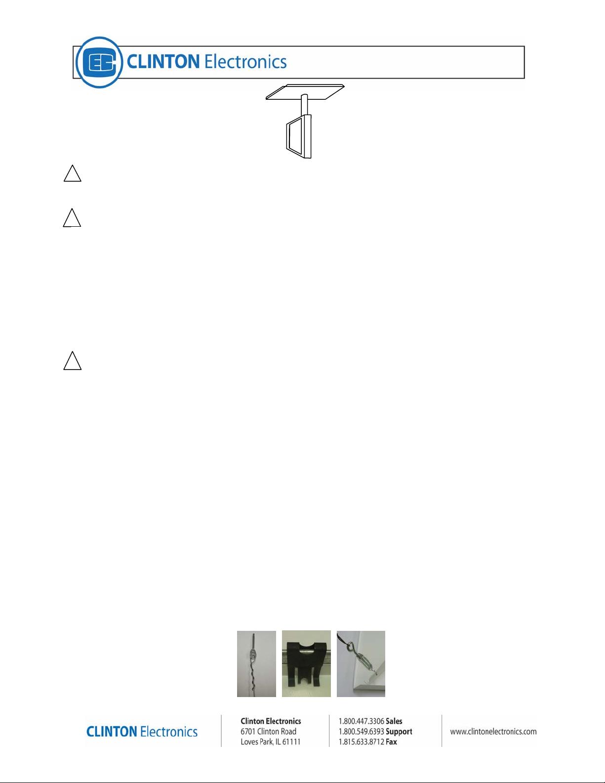
1.1.1 For Steel Trusses or Beams, secure a 3/16” dia minimum eye bolt to the structure
and attach the Annealed Safety Wire through the eye and wrap the wire on itself a
minimum of three (3) wraps. (Figure 1)
1.1.2 For Concrete ceilings, attach with Tie Wire Concrete Anchors (3/16” dia minimum)
such as ITW-Redhead #TD4-112 Redi-Drive, or ITW-Redhead ¼” x 1-1/2” RediDrive Tie Wire Anchors available at Home Centers. Anchors must be rated a
minimum of 200 pounds in tension. Attach the Annealed Wire through the anchor
eye back on itself with a minimum of three (3) wraps. (Figure 1)
1.1.3 For Wood Truss/stud ceilings, use a 3/16” dia screw eye with a minimum penetration
into the wood of 1”. Attach the Annealed Wire with a minimum of three (3) wraps.
1.2 Locate the Ceiling Tile in the desired location of the suspended grid structure. If installing in
a 2ft x 4ft tile space, an additional cross tee (not included) must be used to fully support the
tile on all four sides.
1.3 Install (2) Safety Clips over Grid “T” to hold 2x2 panel in place (see figure 2).
1.4 Located in the corners of the 2x2 tile, there are four holes in the gussets. Insert the (4)
turnbuckles into these holes and twist the body to open (lengthen) them. Using the included
Annealed Safety Wire, secure the (4) turnbuckles to the attachment point above (see Figure
3). The weight of the mount and monitor should be supported by the Safety Wire, not the TGrid structure. Tighten (shorten) the turnbuckles by twisting the body until the wire is taught
and the weight of the Mount and contents is fully supported by the Annealed Safety Wire and
not the Ceiling T-Bar Grid. Re-tension if necessary after assembly is complete.
Pg 2
Page 3

Figure 1 Figure 2 Figure 3
2.0 Install Column to Ceiling Tile.
2.1 Insert Column up through the center hole on the bottom of the Ceiling Tile with the Column
end that has two (2) holes facing down.
2.2 Install Collar over tubing from above the Ceiling Tile and tighten set screw to achieve desired
height of Column below Panel.
2.3 Insert a #10-24 x 2-1/4 Pan Head Screw and Flat Washers through the top hole in the
Column and tighten with #10-24 Lock Nut.
! CAUTION: This screw acts as a safety feature in the event the collar should slip on the shaft and
must be installed.
2.4 Install two (2) Plastic Angle Shims between the Column and the Tile Gussets above the Tile
surface to lock the column in place (figure 4).
2.5 Insert one (1) Snap Bushing in each end of the Column.
2.6 Run Power and Video cabling through Column, along with the Safety Cable at this time. The
Safety Cable ring eye is to be located at the lower end of the column.
2.7 Attach the plain end of the Safety Cable to the permanent structure directly above the
Column using the included Cable Clamp to loop around the structure and secure the cable to
itself (see figure 5). The end with the lug should extend approx 2” below the Column opening
at the bottom to attach to the monitor.
Figure 4 Figure 5
3.0 Install VESA Plate to Column
3.1 Orient VESA Plate so the arc slot on the two tabs is up. Using two (2) #10-24x2-1/4” Pan
Head Screws, four (4) #10 Flat Washers, and two (2) #10-24 Locknuts, assemble VESA
Plate to bottom of column as shown in Figure 6.
4.0 Install Monitor to VESA Plate
4.1 Using three (3) M4x8 Pan Head Screws, attach Monitor to VESA Plate at the corresponding
holes as shown in Figure 6.
5.0 Install Safety Cable to Monitor
5.1 Using the M4x10 Pan Head Screw included with the Safety Cable, attach the Lugged end of
the Safety Cable to the fourth VESA screw hole as shown in Figure 7.
! CAUTION: This Safety Cable is a safety feature designed to prevent the monitor and bracket from
falling and causing injuries to personnel or property below the Ceiling Mount should some part of the
Ceiling Mount’s structure fail.
Pg 3
Page 4

Figure 6 Figure 7
Pg 4
 Loading...