

Page 1

BOILER
GUN
BG22 BOILER GUN
OPERATING MANUAL
P/N 100241
August 2017
Revision 1
Page 2

Page 3

TABLE OF CONTENTS
CHAPTER/SECTION PAGE
INTRODUCTION 1
1.1 HOW TO USE THIS MANUAL . . . . . . . . . . . . . . . . . . . . . . . . . . . . . . . . . . . . . . . . . . . . . . . . . . . . . . . . . . 1
1.2 S
1.3 G
1.4 M
1.5 R
1.6 R
1.7 L
AFETY ALERTS . . . . . . . . . . . . . . . . . . . . . . . . . . . . . . . . . . . . . . . . . . . . . . . . . . . . . . . . . . . . . . . . . . 1
ENERAL SAFETY PRECAUTIONS. . . . . . . . . . . . . . . . . . . . . . . . . . . . . . . . . . . . . . . . . . . . . . . . . . . . . . 2
ACHINE-SPECIFIC SAFETY PRECAUTIONS. . . . . . . . . . . . . . . . . . . . . . . . . . . . . . . . . . . . . . . . . . . . . . . 3
ISK ASSESSMENT AND HAZARD MITIGATION . . . . . . . . . . . . . . . . . . . . . . . . . . . . . . . . . . . . . . . . . . . . . 4
ISK ASSESSMENT CHECKLIST . . . . . . . . . . . . . . . . . . . . . . . . . . . . . . . . . . . . . . . . . . . . . . . . . . . . . . . 5
ABELS . . . . . . . . . . . . . . . . . . . . . . . . . . . . . . . . . . . . . . . . . . . . . . . . . . . . . . . . . . . . . . . . . . . . . . . . 6
1.7.1 Label identification . . . . . . . . . . . . . . . . . . . . . . . . . . . . . . . . . . . . . . . . . . . . . . . . . . . . . . . . . . 6
1.7.2 Label location . . . . . . . . . . . . . . . . . . . . . . . . . . . . . . . . . . . . . . . . . . . . . . . . . . . . . . . . . . . . . . 7
OVERVIEW 9
2.1 FEATURES AND COMPONENTS. . . . . . . . . . . . . . . . . . . . . . . . . . . . . . . . . . . . . . . . . . . . . . . . . . . . . . . . 9
2.2 C
2.3 D
2.4 S
2.5 I
ONTROLS. . . . . . . . . . . . . . . . . . . . . . . . . . . . . . . . . . . . . . . . . . . . . . . . . . . . . . . . . . . . . . . . . . . . . 10
2.2.1 Pneumatic motor controls . . . . . . . . . . . . . . . . . . . . . . . . . . . . . . . . . . . . . . . . . . . . . . . . . . . . 10
2.2.2 Electric motor controls. . . . . . . . . . . . . . . . . . . . . . . . . . . . . . . . . . . . . . . . . . . . . . . . . . . . . . . 10
2.2.3 Cordless electric motor controls . . . . . . . . . . . . . . . . . . . . . . . . . . . . . . . . . . . . . . . . . . . . . . . 10
IMENSIONS . . . . . . . . . . . . . . . . . . . . . . . . . . . . . . . . . . . . . . . . . . . . . . . . . . . . . . . . . . . . . . . . . . . 11
PECIFICATIONS. . . . . . . . . . . . . . . . . . . . . . . . . . . . . . . . . . . . . . . . . . . . . . . . . . . . . . . . . . . . . . . . . 12
TEMS REQUIRED BUT NOT SUPPLIED. . . . . . . . . . . . . . . . . . . . . . . . . . . . . . . . . . . . . . . . . . . . . . . . . . 12
SETUP 13
3.1 RECEIPT AND INSPECTION . . . . . . . . . . . . . . . . . . . . . . . . . . . . . . . . . . . . . . . . . . . . . . . . . . . . . . . . . 13
3.2 M
ACHINE SETUP . . . . . . . . . . . . . . . . . . . . . . . . . . . . . . . . . . . . . . . . . . . . . . . . . . . . . . . . . . . . . . . . 14
3.2.1 Wedge locking system . . . . . . . . . . . . . . . . . . . . . . . . . . . . . . . . . . . . . . . . . . . . . . . . . . . . . . 14
3.2.2 Collet locking system . . . . . . . . . . . . . . . . . . . . . . . . . . . . . . . . . . . . . . . . . . . . . . . . . . . . . . . 15
3.2.3 Tool holders . . . . . . . . . . . . . . . . . . . . . . . . . . . . . . . . . . . . . . . . . . . . . . . . . . . . . . . . . . . . . . 15
3.2.4 Center shafts. . . . . . . . . . . . . . . . . . . . . . . . . . . . . . . . . . . . . . . . . . . . . . . . . . . . . . . . . . . . . . 15
3.3 M
3.4 I
3.5 M
ACHINE MOUNTING . . . . . . . . . . . . . . . . . . . . . . . . . . . . . . . . . . . . . . . . . . . . . . . . . . . . . . . . . . . . . 16
NSTALLING THE CUTTING TOOLS. . . . . . . . . . . . . . . . . . . . . . . . . . . . . . . . . . . . . . . . . . . . . . . . . . . . . 17
OTORS . . . . . . . . . . . . . . . . . . . . . . . . . . . . . . . . . . . . . . . . . . . . . . . . . . . . . . . . . . . . . . . . . . . . . . 18
3.5.1 Pneumatic motor . . . . . . . . . . . . . . . . . . . . . . . . . . . . . . . . . . . . . . . . . . . . . . . . . . . . . . . . . . . 18
3.5.2 Electric motor . . . . . . . . . . . . . . . . . . . . . . . . . . . . . . . . . . . . . . . . . . . . . . . . . . . . . . . . . . . . . 18
3.5.3 Cordless electric motor . . . . . . . . . . . . . . . . . . . . . . . . . . . . . . . . . . . . . . . . . . . . . . . . . . . . . . 18
OPERATION 19
4.1 PRE-OPERATION CHECKS . . . . . . . . . . . . . . . . . . . . . . . . . . . . . . . . . . . . . . . . . . . . . . . . . . . . . . . . . . 19
4.2 O
PERATION . . . . . . . . . . . . . . . . . . . . . . . . . . . . . . . . . . . . . . . . . . . . . . . . . . . . . . . . . . . . . . . . . . . . 19
4.2.1 Pneumatic motor . . . . . . . . . . . . . . . . . . . . . . . . . . . . . . . . . . . . . . . . . . . . . . . . . . . . . . . . . . . 19
P/N 100241, Rev. 1 Page i
Page 4

TABLE OF CONTENTS (CONTINUED)
CHAPTER/SECTION PAGE
4.2.2 Electric motor . . . . . . . . . . . . . . . . . . . . . . . . . . . . . . . . . . . . . . . . . . . . . . . . . . . . . . . . . . . . . 20
MAINTENANCE 21
5.1 MAINTENANCE CHECKLIST . . . . . . . . . . . . . . . . . . . . . . . . . . . . . . . . . . . . . . . . . . . . . . . . . . . . . . . . . 21
5.2 A
5.3 M
5.4 T
STORAGE AND SHIPPING 25
6.1 STORAGE . . . . . . . . . . . . . . . . . . . . . . . . . . . . . . . . . . . . . . . . . . . . . . . . . . . . . . . . . . . . . . . . . . . . . 25
6.2 S
6.3 D
PPROVED LUBRICANTS . . . . . . . . . . . . . . . . . . . . . . . . . . . . . . . . . . . . . . . . . . . . . . . . . . . . . . . . . . . 21
AINTENANCE TASKS . . . . . . . . . . . . . . . . . . . . . . . . . . . . . . . . . . . . . . . . . . . . . . . . . . . . . . . . . . . . . 22
5.3.1 Checking and filling the in-line oiler reservoir . . . . . . . . . . . . . . . . . . . . . . . . . . . . . . . . . . . . . 22
5.3.2 Servicing the filter element . . . . . . . . . . . . . . . . . . . . . . . . . . . . . . . . . . . . . . . . . . . . . . . . . . . 22
5.3.3 Adjusting the oil flow rate of the in-line oiler . . . . . . . . . . . . . . . . . . . . . . . . . . . . . . . . . . . . . . 22
5.3.4 Tool holders . . . . . . . . . . . . . . . . . . . . . . . . . . . . . . . . . . . . . . . . . . . . . . . . . . . . . . . . . . . . . . 23
5.3.5 Greasing the drive and pinion gears . . . . . . . . . . . . . . . . . . . . . . . . . . . . . . . . . . . . . . . . . . . . 23
ROUBLESHOOTING . . . . . . . . . . . . . . . . . . . . . . . . . . . . . . . . . . . . . . . . . . . . . . . . . . . . . . . . . . . . . . 23
5.4.1 The machine isn’t turning . . . . . . . . . . . . . . . . . . . . . . . . . . . . . . . . . . . . . . . . . . . . . . . . . . . . 23
5.4.2 The machine isn’t feeding . . . . . . . . . . . . . . . . . . . . . . . . . . . . . . . . . . . . . . . . . . . . . . . . . . . . 23
5.4.3 The machine is performing poorly. . . . . . . . . . . . . . . . . . . . . . . . . . . . . . . . . . . . . . . . . . . . . . 23
6.1.1 Short-term storage . . . . . . . . . . . . . . . . . . . . . . . . . . . . . . . . . . . . . . . . . . . . . . . . . . . . . . . . . 25
6.1.2 Long-term storage. . . . . . . . . . . . . . . . . . . . . . . . . . . . . . . . . . . . . . . . . . . . . . . . . . . . . . . . . . 25
HIPPING. . . . . . . . . . . . . . . . . . . . . . . . . . . . . . . . . . . . . . . . . . . . . . . . . . . . . . . . . . . . . . . . . . . . . . 26
ECOMMISSIONING . . . . . . . . . . . . . . . . . . . . . . . . . . . . . . . . . . . . . . . . . . . . . . . . . . . . . . . . . . . . . . 26
ASSEMBLY DRAWINGS 27
SDS 39
Page ii
Page 5

LIST OF FIGURES
FIGURE PAGE
1-1 BG22 Boiler Gun, pneumatic label location. . . . . . . . . . . . . . . . . . . . . . . . . . . . . . . . . . . . . . . . . . . . . . . 7
1-2 BG22 Boiler Gun, electric label location . . . . . . . . . . . . . . . . . . . . . . . . . . . . . . . . . . . . . . . . . . . . . . . . . 8
2-1 BG22 and shipping container . . . . . . . . . . . . . . . . . . . . . . . . . . . . . . . . . . . . . . . . . . . . . . . . . . . . . . . . . 9
2-2 Pneumatic motor throttle lever. . . . . . . . . . . . . . . . . . . . . . . . . . . . . . . . . . . . . . . . . . . . . . . . . . . . . . . . 10
2-3 Direction and trigger controls. . . . . . . . . . . . . . . . . . . . . . . . . . . . . . . . . . . . . . . . . . . . . . . . . . . . . . . . . 10
2-4 Cordless motor controls. . . . . . . . . . . . . . . . . . . . . . . . . . . . . . . . . . . . . . . . . . . . . . . . . . . . . . . . . . . . . 11
2-5 BG22 Boiler Gun dimensions . . . . . . . . . . . . . . . . . . . . . . . . . . . . . . . . . . . . . . . . . . . . . . . . . . . . . . . . 11
3-1 BG22 Boiler Gun main components . . . . . . . . . . . . . . . . . . . . . . . . . . . . . . . . . . . . . . . . . . . . . . . . . . . 14
3-2 Installed wedge set with extensions . . . . . . . . . . . . . . . . . . . . . . . . . . . . . . . . . . . . . . . . . . . . . . . . . . . 14
3-3 Small wedge set . . . . . . . . . . . . . . . . . . . . . . . . . . . . . . . . . . . . . . . . . . . . . . . . . . . . . . . . . . . . . . . . . . 15
3-4 Installed collet set . . . . . . . . . . . . . . . . . . . . . . . . . . . . . . . . . . . . . . . . . . . . . . . . . . . . . . . . . . . . . . . . . 15
3-5 Changing the center shaft . . . . . . . . . . . . . . . . . . . . . . . . . . . . . . . . . . . . . . . . . . . . . . . . . . . . . . . . . . . 16
3-6 BG22 Boiler Gun installed in workpiece . . . . . . . . . . . . . . . . . . . . . . . . . . . . . . . . . . . . . . . . . . . . . . . . 16
3-7 Locking rod wrench with speed wheel. . . . . . . . . . . . . . . . . . . . . . . . . . . . . . . . . . . . . . . . . . . . . . . . . . 16
3-8 Sliding tool holder . . . . . . . . . . . . . . . . . . . . . . . . . . . . . . . . . . . . . . . . . . . . . . . . . . . . . . . . . . . . . . . . . 17
3-9 Cutting bit installed . . . . . . . . . . . . . . . . . . . . . . . . . . . . . . . . . . . . . . . . . . . . . . . . . . . . . . . . . . . . . . . . 17
3-10 Universal coupler (top) and quick disconnect (bottom) . . . . . . . . . . . . . . . . . . . . . . . . . . . . . . . . . . . . 18
3-11 Motor direction control set to forward . . . . . . . . . . . . . . . . . . . . . . . . . . . . . . . . . . . . . . . . . . . . . . . . . 18
4-1 Hand positioning during boiler gun operation. . . . . . . . . . . . . . . . . . . . . . . . . . . . . . . . . . . . . . . . . . . . . 19
4-2 BG22 with electric motor . . . . . . . . . . . . . . . . . . . . . . . . . . . . . . . . . . . . . . . . . . . . . . . . . . . . . . . . . . . . 20
5-1 In-line oiler sight glass . . . . . . . . . . . . . . . . . . . . . . . . . . . . . . . . . . . . . . . . . . . . . . . . . . . . . . . . . . . . . . 22
6-1 BG22 shipping container . . . . . . . . . . . . . . . . . . . . . . . . . . . . . . . . . . . . . . . . . . . . . . . . . . . . . . . . . . . . 26
A-1 BG22 boiler gun pneumatic assembly (P/N BG22). . . . . . . . . . . . . . . . . . . . . . . . . . . . . . . . . . . . . . . . 28
A-2 BG22 boiler gun electric assembly (P/N BG22E) . . . . . . . . . . . . . . . . . . . . . . . . . . . . . . . . . . . . . . . . . 29
A-3 BG22 boiler gun cordless electric assembly (P/N BG22C) . . . . . . . . . . . . . . . . . . . . . . . . . . . . . . . . . . 30
A-4 Collet components and collets . . . . . . . . . . . . . . . . . . . . . . . . . . . . . . . . . . . . . . . . . . . . . . . . . . . . . . . 31
A-5 Wedge sets and wedge extensions . . . . . . . . . . . . . . . . . . . . . . . . . . . . . . . . . . . . . . . . . . . . . . . . . . . 32
A-6 Wedge set components . . . . . . . . . . . . . . . . . . . . . . . . . . . . . . . . . . . . . . . . . . . . . . . . . . . . . . . . . . . . 33
A-7 Small wedge set components . . . . . . . . . . . . . . . . . . . . . . . . . . . . . . . . . . . . . . . . . . . . . . . . . . . . . . . . 34
A-8 Tool holders . . . . . . . . . . . . . . . . . . . . . . . . . . . . . . . . . . . . . . . . . . . . . . . . . . . . . . . . . . . . . . . . . . . . . 34
A-9 Air motor assembly and parts list (P/N CML3488) . . . . . . . . . . . . . . . . . . . . . . . . . . . . . . . . . . . . . . . . 35
A-10 Air hose assembly and parts list (P/N HS 50-509) . . . . . . . . . . . . . . . . . . . . . . . . . . . . . . . . . . . . . . . 36
A-11 Electric motor assembly and parts list (P/N EB002615) . . . . . . . . . . . . . . . . . . . . . . . . . . . . . . . . . . . 37
A-12 Tool kit. . . . . . . . . . . . . . . . . . . . . . . . . . . . . . . . . . . . . . . . . . . . . . . . . . . . . . . . . . . . . . . . . . . . . . . . . 38
A-13 Shipping container . . . . . . . . . . . . . . . . . . . . . . . . . . . . . . . . . . . . . . . . . . . . . . . . . . . . . . . . . . . . . . . 38
P/N 100241, Rev. 1 Page iii
Page 6

This page intentionally left blank
Page iv
Page 7

LIST OF TABLES
TABLE PAGE
1-1 Sound levels . . . . . . . . . . . . . . . . . . . . . . . . . . . . . . . . . . . . . . . . . . . . . . . . . . . . . . . . . . . . . . . . . . . . . . 3
1-2 Risk assessment checklist before set-up . . . . . . . . . . . . . . . . . . . . . . . . . . . . . . . . . . . . . . . . . . . . . . . . 5
1-3 Risk assessment checklist after set-up . . . . . . . . . . . . . . . . . . . . . . . . . . . . . . . . . . . . . . . . . . . . . . . . . . 5
1-4 BG22 Boiler Gun labels. . . . . . . . . . . . . . . . . . . . . . . . . . . . . . . . . . . . . . . . . . . . . . . . . . . . . . . . . . . . . . 6
2-1 Sub-component mass . . . . . . . . . . . . . . . . . . . . . . . . . . . . . . . . . . . . . . . . . . . . . . . . . . . . . . . . . . . . . . 12
5-1 Maintenance intervals and tasks . . . . . . . . . . . . . . . . . . . . . . . . . . . . . . . . . . . . . . . . . . . . . . . . . . . . . . 21
5-2 Approved lubricants. . . . . . . . . . . . . . . . . . . . . . . . . . . . . . . . . . . . . . . . . . . . . . . . . . . . . . . . . . . . . . . . 22
P/N 100241, Rev. 1 Page v
Page 8

This page intentionally left blank
Page vi
Page 9

©2017 Climax Portable Machining and Welding Systems or its subsidiaries.
All rights reserved.
Except as expressly provided herein, no part of this manual may be reproduced, copied, transmitted, disseminated,
downloaded, or stored in any storage medium, without the express prior written consent of Climax. Climax hereby
grants permission to download a single copy of this manual and of any revision hereto onto an electronic storage
medium to be viewed and to print one copy of this manual or any revision hereto, provided that such electronic or
printed copy of this manual or revision must contain the complete text of this copyright notice and provided further
that any unauthorized commercial distribution of this manual or any revision hereto is prohibited.
At Climax Portable Machining and Welding Systems, we value your opinion.
For comments or questions about this manual or other Climax documentation, please e-mail
documentation@cpmt.com.
For comments or questions about Climax products or services, please call Climax or e-mail
quick and accurate service, please provide your factory representative with the following:
•Your name
• Shipping address
• Telephone number
• Machine model
• Serial number (if applicable)
•Date of purchase
info@cpmt.com. For
Climax World Headquarters
Climax Portable Machining and Welding Systems
2712 South Second Street Newberg, Oregon 97132 USA
Telephone (worldwide): (503) 538-2815
Toll-free (North America):1-800-333-8311
Fax: 503.538.7600
E-mail:
info@cpmt.com
Climax UK Headquarters
Climax Portable Machine Tools Ltd
Unit 10 Heather Close
Lyme Green Business Park
Macclesfield, Cheshire SK11 0LR, UK
Telephone: +44 (0) 161 406 1720
E-mail:
info@cpmt.com
Climax European Headquarters
Climax GmbH
Am Langen Graben 8
52353 Düren, Germany
Telephone: +49 (0) 2421-9177-12
E-mail:
info@cpmt.de
P/N 100241, Rev. 1 Page A
Page 10

CLIMAX GLOBAL LOCATIONS
Page B
Page 11

CE DOCUMENTATION
CE Certification is pending
P/N 100241, Rev. 1 Page C
Page 12

LIMITED WARRANTY
Climax Portable Machine Tools, Inc. (hereafter referred to as “Climax”) warrants that all new machines are free
from defects in materials and workmanship. This warranty is available to the original purchaser for a period of one
year after delivery. If the original purchaser finds any defect in materials or workmanship within the warranty
period, the original purchaser should contact its factory representative and return the entire machine, shipping prepaid, to the factory. Climax will, at its option, either repair or replace the defective machine at no charge and will
return the machine with shipping prepaid.
Climax warrants that all parts are free from defects in materials and workmanship, and that all labor has been performed properly. This warranty is available to the customer purchasing parts or labor for a period of 90 days after
delivery of the part or repaired machine or 180 days on used machines and components. If the customer purchasing
parts or labor finds any defect in materials or workmanship within the warranty period, the purchaser should contact its factory representative and return the part or repaired machine, shipping prepaid, to the factory. Climax
will, at its option, either repair or replace the defective part and/ or correct any defect in the labor performed,
both at no charge, and return the part or repaired machine shipping prepaid.
These warranties do not apply to the following:
• Damage after the date of shipment not caused by defects in materials or workmanship
• Damage caused by improper or inadequate machine maintenance
• Damage caused by unauthorized machine modification or repair
• Damage caused by machine abuse
• Damage caused by using the machine beyond its rated capacity
All other warranties, express or implied, including without limitation the warranties of merchantability and fitness
for a particular purpose are disclaimed and excluded.
Terms of sale
Be sure to review the terms of sale which appear on the reverse side of your invoice. These terms control and limit
your rights with respect to the goods purchased from Climax.
About this manual
Climax provides the contents of this manual in good faith as a guideline to the operator. Climax cannot guarantee
that the information contained in this manual is correct for applications other than the application described in this
manual. Product specifications are subject to change without notice.
Page D
Page 13
1 INTRODUCTION
DANGER
WARNING
CAUTION
NOTICE
IN THIS CHAPTER:
1.1 HOW TO USE THIS MANUAL - - - - - - - - - - - - - - - - - - - - - - - - - - - - - - - - - - - - - - 1
1.2 S
AFETY ALERTS - - - - - - - - - - - - - - - - - - - - - - - - - - - - - - - - - - - - - - - - - - - 1
ENERAL SAFETY PRECAUTIONS - - - - - - - - - - - - - - - - - - - - - - - - - - - - - - - - - - - 2
1.3 G
ACHINE-SPECIFIC SAFETY PRECAUTIONS - - - - - - - - - - - - - - - - - - - - - - - - - - - - - - - 3
1.4 M
1.5 R
ISK ASSESSMENT AND HAZARD MITIGATION - - - - - - - - - - - - - - - - - - - - - - - - - - - - - - 4
ISK ASSESSMENT CHECKLIST - - - - - - - - - - - - - - - - - - - - - - - - - - - - - - - - - - - - 5
1.6 R
ABELS - - - - - - - - - - - - - - - - - - - - - - - - - - - - - - - - - - - - - - - - - - - - - - - 6
1.7 L
1.7.1 L
ABEL IDENTIFICATION - - - - - - - - - - - - - - - - - - - - - - - - - - - - - - - - - - - - - 6
ABEL LOCATION - - - - - - - - - - - - - - - - - - - - - - - - - - - - - - - - - - - - - - - - 7
1.7.2 L
1.1 HOW TO USE THIS MANUAL
This manual describes information necessary for the
setup, operation, maintenance, storage, shipping, and
decommissioning of the BG22 Boiler Gun.
The first page of each chapter includes a summary of
the chapter contents to help you locate specific information. The appendices contain supplemental product
information to aid in setup, operation, and maintenance
tasks.
1.2 SAFETY ALERTS
Pay careful attention to the safety alerts printed
throughout this manual. Safety alerts will call your
attention to specific hazardous situations that may be
encountered when operating this machine.
Examples of safety alerts used in this manual are
defined here
1
:
indicates a hazardous situation which, if not
avoided, WILL result in death or severe
injury.
Read this entire manual to familiarize yourself with the
BG22 Boiler Gun before attempting to set it up or operate it.
indicates a hazardous situation which, if not
avoided, COULD result in death or severe
injury.
indicates a hazardous situation which, if not
avoided, could result in minor or moderate
injury.
1. For more information on safety alerts, refer to ANSI/NEMA
Z535.6-2011, Product safety Information in Product
Manuals, Instructions, and Other Collateral Materials
P/N 100241, Rev. 1 Page 1
indicates a hazardous situation which, if not
avoided, could result in property damage,
equipment failure, or undesired work
results
.
Page 14

1.3 GENERAL SAFETY PRECAUTIONS
H&S leads the way in promoting the safe use of portable
machine tools. Safety is a joint effort. You, the end
user, must do your part by being aware of your work
environment and closely following the operating procedures and safety precautions contained in this manual,
as well as your employer’s safety guidelines.
Observe the following safety precautions when operating or working around the machine.
Training – Before operating this or any machine
tool, you should receive instruction from a qualified trainer. Contact H&S for machine-specific
training information.
Risk assessment – Working with and around this
machine poses risks to your safety. You, the end
user, are responsible for conducting a risk
assessment of each job site before setting up
and operating this machine.
Intended use – Use this machine in accordance with
the instructions and precautions in this manual.
Do not use this machine for any purpose other
than its intended use as described in this manual.
Personal protective equipment – Always wear
appropriate personal protective gear when
operating this or any other machine tool.
Flame-resistant clothing with long sleeves and
legs is recommended when operating the
machine. Hot chips from the workpiece may
burn or cut bare skin.
Work area – Keep the work area around the
machine clear of clutter. Restrain cords and
hoses connected to the machine. Keep other
cords and hoses away from the work area.
Lifting – Many H&S machine components are very
heavy. Whenever possible, lift the machine or
its components using proper hoisting equipment
and rigging. Always use designated lifting points
on the machine. Follow lifting instructions in
the setup procedures of this manual.
Lock-out/tag-out – Lock-out and tag-out the
machine before performing maintenance.
Moving parts – H&S machines have numerous
exposed moving parts and interfaces that can
cause severe impact, pinching, cutting, and
other injuries. Except for stationary operating
controls, avoid contact with moving parts by
hands or tools during machine operation.
Remove gloves and secure hair, clothing, jewelry, and pocket items to prevent them from
becoming entangled in moving parts.
Sharp edges – Cutting tools and workpieces have
sharp edges that can easily cut skin. Wear protective gloves and exercise caution when handling a cutting tool or workpiece.
Hot surfaces – During operation, motors, pumps,
HPUs, and cutting tools can generate enough
heat to cause severe burns. Pay attention to hot
surface labels, and avoid contact with bare skin
until the machine has cooled.
Page 2 BG22 Boiler Gun Operating Manual
Page 15

1.4 MACHINE-SPECIFIC SAFETY PRECAUTIONS
Eye hazard – This machine produces metal chips
during operation. Always wear eye protection
when operating the machine.
Hazardous environments – Do not operate the
machine in environments where potentially
explosive materials, toxic chemicals, or radiation may be present.
Sound level – This machine produces potentially
harmful sound levels. Hearing protection is required
when operating this machine or working around it.
During testing, the machine produced the sound
1
levels
listed in Table 1-1.
TABLE 1-1. SOUND LEVELS
S
Pneumatic Motor
Average sound pressure 90.6 dBA
Operator sound pressure 91.5 dBA
Bystander sound pressure 89.4 dBA
Electric Motor
Average sound pressure 85 dBA
Operator sound pressure 85 dBA
Bystander sound pressure 85 dBA
1. Machine sound testing was conducted in accordance with European Harmonized Standards EN ISO 3744:2010 and EN 11201:2010.
P/N 100241, Rev. 1 Page 3
Page 16

1.5 RISK ASSESSMENT AND HAZARD MITIGATION
Machine Tools are specifically designed to perform precise material-removal operations.
Stationary Machine Tools include lathes and milling
machines and are typically found in a machine shop.
They are mounted in a fixed location during operation
and are considered to be a complete, self-contained
machine. Stationary Machine Tools achieve the rigidity
needed to accomplish material-removal operations from
the structure that is an integral part of the machine
tool.
In contrast, Portable Machine Tools are designed for onsite machining applications. They typically attach
directly to the workpiece itself, or to an adjacent structure, and achieve their rigidity from the structure to
which it is attached. The design intent is that the Portable Machine Tool and the structure to which it is
attached become one complete machine during the
material-removal process.
To achieve the intended results and to promote safety,
the operator must understand and follow the design
intent, set-up, and operation practices that are unique
to Portable Machine Tools valve testers.
The operator must perform an overall review and onsite risk assessment of the intended application. Due to
the unique nature of portable machining applications
hydrostatic testing, identifying one or more hazards
that must be addressed is typical.
When performing the on-site risk assessment, it is
important to consider the Portable Machine Tool valve
tester and the workpiece as a whole.
Page 4 BG22 Boiler Gun Operating Manual
Page 17

1.6 RISK ASSESSMENT CHECKLIST
The following checklist is not intended to be an all
inclusive list of things to watch out for when setting up
and operating this Portable Machine Tool.
TABLE 1-2. RISK ASSESSMENT CHECKLIST BEFORE SET-UP
Before set-up
I took note of all the warning labels on the machine.
I removed or mitigated all identified risks (such as tripping, cutting, crushing, entanglement, shearing, or falling objects).
I considered the need for personnel safety guarding and installed any necessary guards.
I read the machine setup instructions (Section 3.2) and took inventory of all the items required but not supplied (Section 2.5).
I considered how this machine operates and identified the best placement for the controls, cabling, and the operator.
I evaluated and mitigated any other potential risks specific to my work area.
ABLE 1-3. RISK ASSESSMENT CHECKLIST AFTER SET-UP
T
After set-up
I checked that the machine is safely installed (according to Section 3) and the potential fall path is clear. If the machine is installed at
an elevated position, I checked that the machine is safeguarded against falling.
I identified all possible pinch points, such as those caused by rotating parts, and informed the affected personnel.
However, these checklists are typical of the types of
risks the assembler and operator should consider. Use
these checklists as part of your risk assessment:
I planned for containment of any chips or swarf produced by the machine.
I followed the required Maintenance Intervals (Section 5.1) with the recommended lubricants (Section 5.2).
I checked that all affected personnel have the recommended personal protective equipment, as well as any site-required or regulatory
equipment.
I checked that all affected personnel understand and are clear of the danger zone.
I evaluated and mitigated any other potential risks specific to my work area.
P/N 100241, Rev. 1 Page 5
Page 18
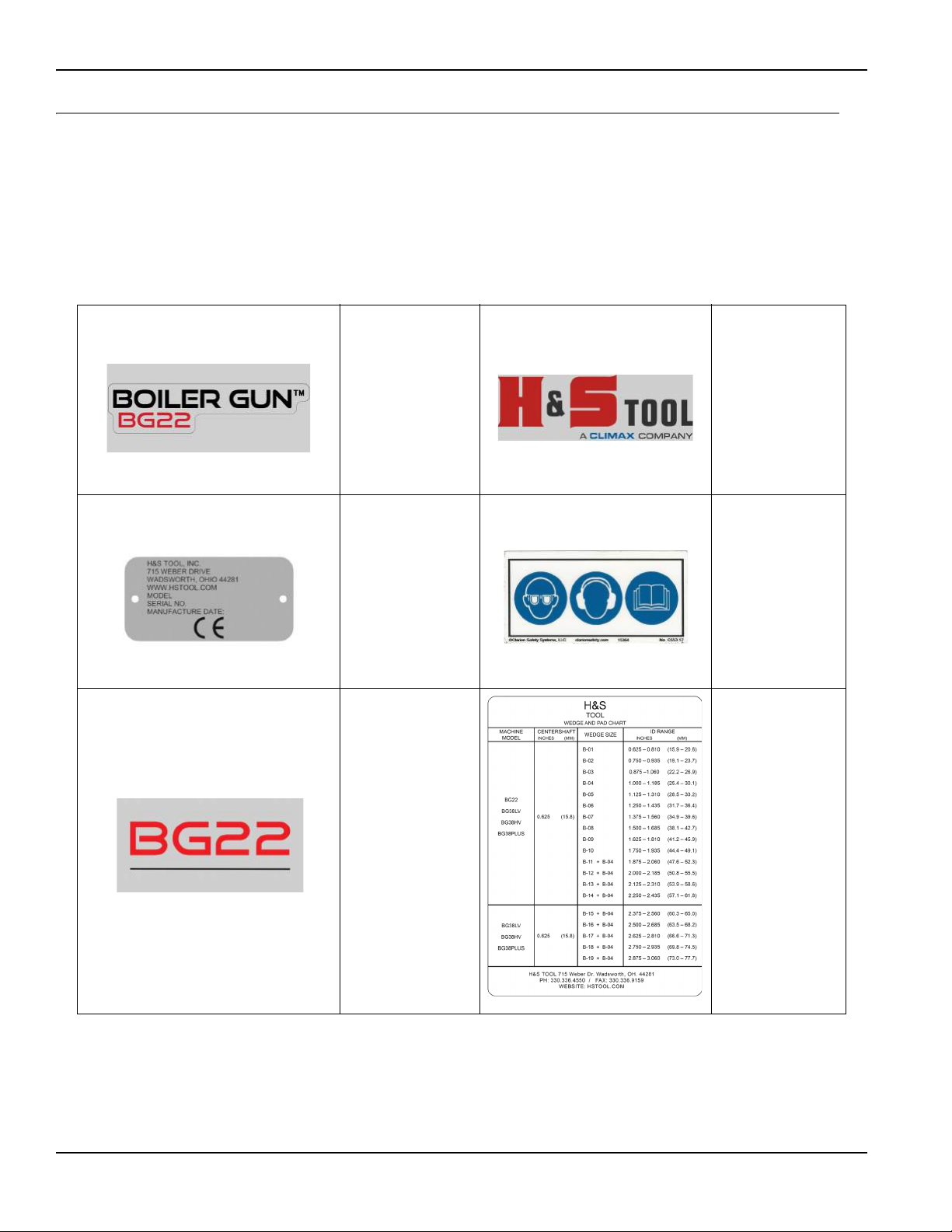
1.7 LABELS
1.7.1 Label identification
The following warning labels should be on your
machine. If any are defaced or missing, contact H&S
Tool immediately for replacements.
TABLE 1-4. BG22 BOILER GUN LABELS
P/N 100204
BG22 Boiler gun label
P/N 100198
H&S serial plate
P/N BG22 container
label
P/N 100199
H&S company label
P/N 87271
Warning label: Use
eye and ear protection, and read the
manual.
P/N 100240
Wedge and pad
chart
Page 6 BG22 Boiler Gun Operating Manual
Page 19

1.7.2 Label location
FIGURE 1-1. BG22 BOILER GUN, PNEUMATIC LABEL LOCATION
The following figures display the location of the labels
on each of the components of the BG22 Boiler Gun.
Label P/N: 100204, 100198, 100199, 87271
P/N 100241, Rev. 1 Page 7
Page 20
Label P/N: 100204, 100198, 100199, 87271
FIGURE 1-2. BG22 BOILER GUN, ELECTRIC LABEL LOCATION
Page 8 BG22 Boiler Gun Operating Manual
Page 21
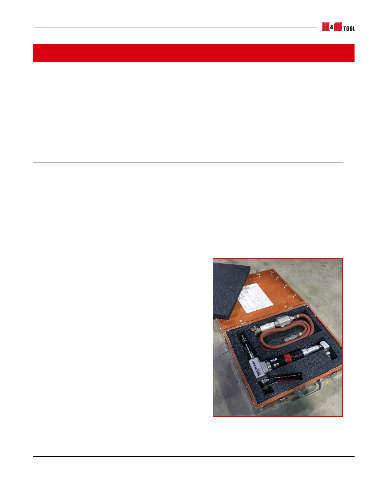
2 OVERVIEW
FIGURE 2-1. BG22 AND SHIPPING CONTAINER
IN THIS CHAPTER:
2.1 FEATURES AND COMPONENTS - - - - - - - - - - - - - - - - - - - - - - - - - - - - - - - - - - - - - 9
2.2 C
ONTROLS - - - - - - - - - - - - - - - - - - - - - - - - - - - - - - - - - - - - - - - - - - - - -10
NEUMATIC MOTOR CONTROLS - - - - - - - - - - - - - - - - - - - - - - - - - - - - - - - - -10
2.2.1 P
LECTRIC MOTOR CONTROLS - - - - - - - - - - - - - - - - - - - - - - - - - - - - - - - - - -10
2.2.2 E
2.2.3 C
ORDLESS ELECTRIC MOTOR CONTROLS - - - - - - - - - - - - - - - - - - - - - - - - - - - - -10
IMENSIONS - - - - - - - - - - - - - - - - - - - - - - - - - - - - - - - - - - - - - - - - - - - - -11
2.3 D
PECIFICATIONS - - - - - - - - - - - - - - - - - - - - - - - - - - - - - - - - - - - - - - - - - - -12
2.4 S
2.5 I
TEMS REQUIRED BUT NOT SUPPLIED - - - - - - - - - - - - - - - - - - - - - - - - - - - - - - - - - -12
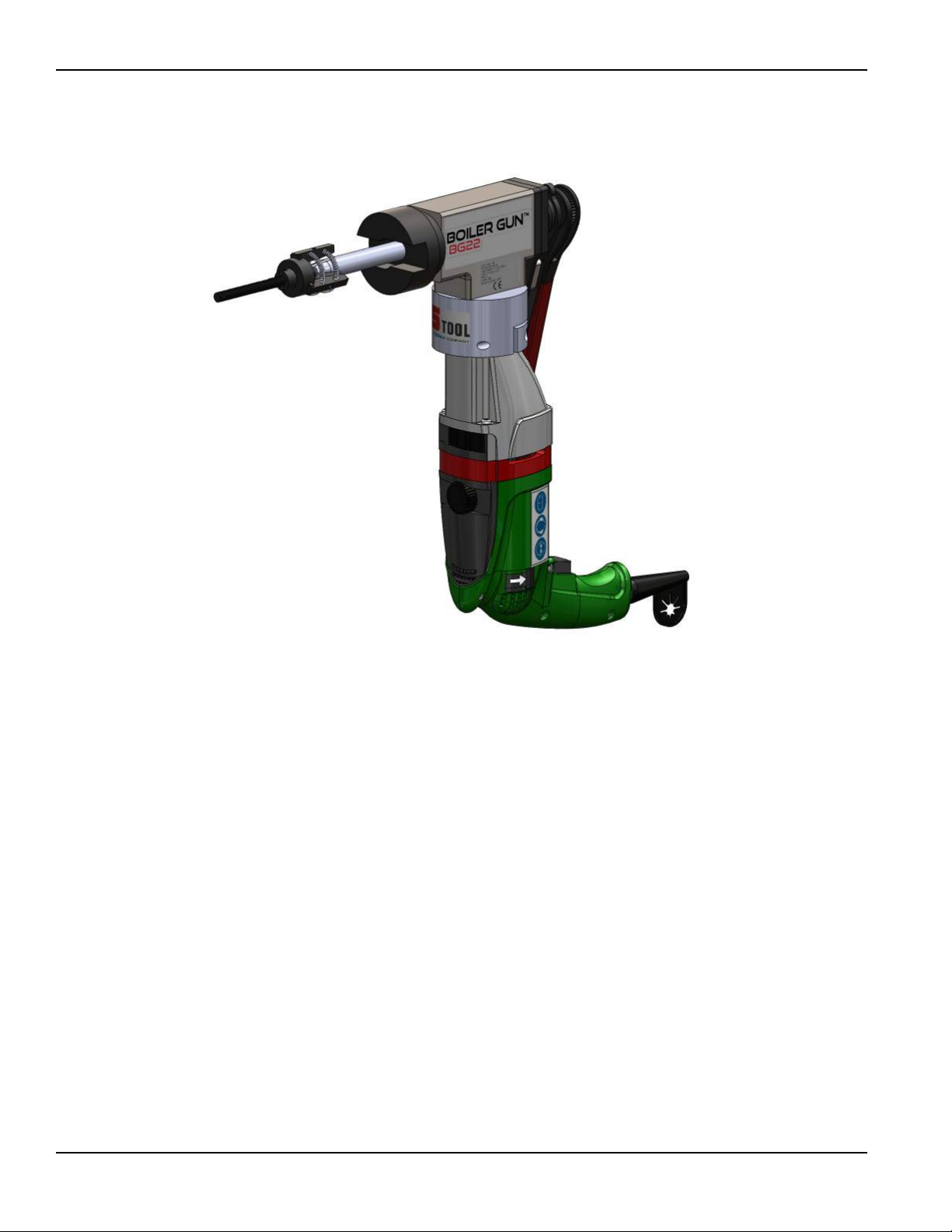
2.1 FEATURES AND COMPONENTS
The BG22 Boiler Gun is a portable, gear-driven, insidediameter (ID)-mounted, single or dual-point beveling
and facing machine for use on workpieces with a range
of .50” (12.7mm) I.D. to 2.50” (63.5mm) O.D.
Principle components include the following:
Drive options: Available with either a 1.3 HP pneu-
matic motor or a 1 HP electric motor.
High Velocity (HV), Low Velocity (LV) and Plus
(PL) gearing-HV delivers higher cutting speeds to
turn specialty carbide inserts, PL offers even higher
speeds for smaller walls in a compact, lighter
machine. LV is geared for heavy walls and hard
alloys.
Mounting systems—Either a wedge or collet mounting system secures the BG22 Boiler Gun to the workpiece. They are both self-centering and adapt to a
wide range of pipe sizes.
Tool holders—Available with either fixed or sliding
tools holders, in multiple sizes.
Torque free operation—Once securely mounted the
BG22 Boiler Gun requires no additional effort to
operate aside from feeding the cutting tool.
Wrench feed—Advances the cutting tools in con-
fined areas with a ratcheting system. This system has a smaller footprint.
Speed wheel—Provides a quicker way to advance
the locking rod nut before fully tightening with
the wrench in confined spaces.
P/N 100241, Rev. 1 Page 9
Page 22
2.2 CONTROLS
WARNING
FIGURE 2-2. PNEUMATIC MOTOR THROTTLE LEVER
FIGURE 2-3. DIRECTION AND TRIGGER CONTROLS
Depending on the user’s requirements, the BG22 Boiler
Gun can be powered by either a pneumatic or electric
motor. The controls for each type of motor follow.
Always stop the machine and disconnect
any power supply before making
adjustments to controls or machine
components. Failure to follow this safety
precaution may result in severe injury.
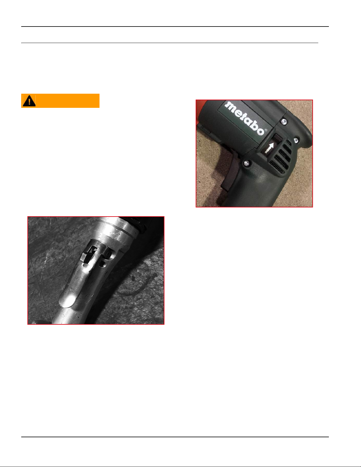
2.2.1 Pneumatic motor controls
The pneumatic motor used on the BG22 features a
throttle lever. The safety lock must be disengaged by
pressing and holding up while depressing the throttle
lever. The throttle lever actuates the motor; when
released, the motor will stop and the safety lock will reengage.
This is an on or off control only.
2.2.2 Electric motor controls
The electric motor controls are similar to a drill or drill
driver. The trigger is squeezed to actuate the motor,
when released the motor will stop.
This speed is controlled by how far the trigger is pulled
in or let out.
The electric motor also has a direction control, which in
this application is not used. The direction control should
always be set to forward.
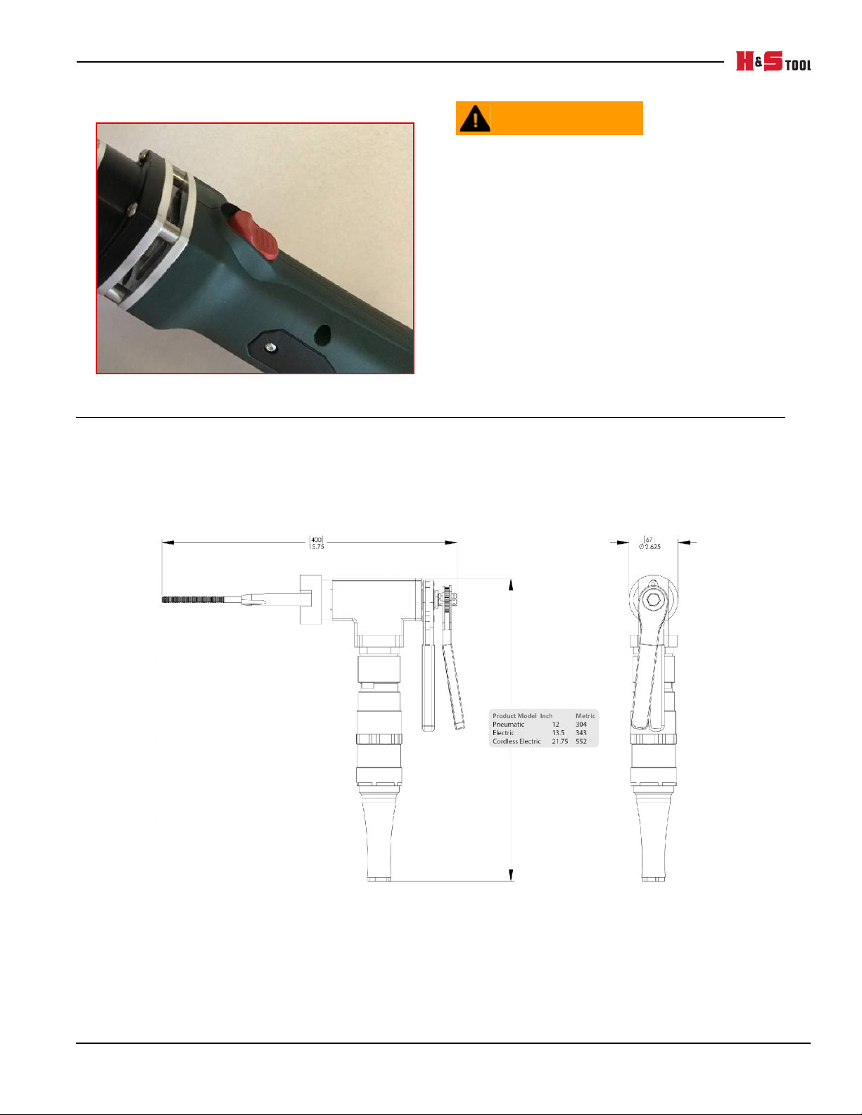
2.2.3 Cordless electric motor controls
To actuate the motor on the cordless electric motor
slide the red button up. The motor will run until the
button is slid down into the off position.
There is no speed or direction controls on the cordless
electric motor.
Page 10 BG22 Boiler Gun Operating Manual
Page 23
WARNING
2.3 DIMENSIONS
FIGURE 2-4. CORDLESS MOTOR CONTROLS
Figure 2-5 shows the machine and operating dimensions.
Do not take any measures to lock the
throttle or the trigger in the on position.
Failure to follow this safety precaution may
result in severe injury.
FIGURE 2-5. BG22 BOILER GUN DIMENSIONS
P/N 100241, Rev. 1 Page 11
Page 24

2.4 SPECIFICATIONS
TABLE 2-1. SUB-COMPONENT MASS
P/N Component Mass in lbs (kg)
BG22 BG22 Boiler Gun Pneumatic 14 (6.4)
BG22E BG22 Boiler Gun Electric 11 (5)
BG22C BG22 Boiler Gun Cordless Electric 16 (7.3)
2.5 ITEMS REQUIRED BUT NOT SUPPLIED
The following items may be required but not supplied in
your H&S product kit:
• Tape measure or steel ruler
• Rubber mallet
•Pliers
Page 12 BG22 Boiler Gun Operating Manual
Page 25

3SETUP
NOTICE
IN THIS CHAPTER:
3.1 RECEIPT AND INSPECTION - - - - - - - - - - - - - - - - - - - - - - - - - - - - - - - - - - - - - -13
ACHINE SETUP - - - - - - - - - - - - - - - - - - - - - - - - - - - - - - - - - - - - - - - - - - -14
3.2 M
3.2.1 W
3.2.2 C
3.2.3 T
3.2.4 C
3.3 M
3.4 I
NSTALLING THE CUTTING TOOLS - - - - - - - - - - - - - - - - - - - - - - - - - - - - - - - - - - -17
3.5 M
3.5.1 P
3.5.2 E
3.5.3 C
This section describes the setup procedures for the
BG22 Boiler Gun.
3.1 RECEIPT AND INSPECTION
EDGE LOCKING SYSTEM - - - - - - - - - - - - - - - - - - - - - - - - - - - - - - - - - - -14
3.2.1.1 S
ACHINE MOUNTING - - - - - - - - - - - - - - - - - - - - - - - - - - - - - - - - - - - - - - - - -16
OTORS - - - - - - - - - - - - - - - - - - - - - - - - - - - - - - - - - - - - - - - - - - - - - -18
MALL I.D. WEDGE LOCKING SYSTEM - - - - - - - - - - - - - - - - - - - - - - - - - - -14
OLLET LOCKING SYSTEM - - - - - - - - - - - - - - - - - - - - - - - - - - - - - - - - - - -15
OOL HOLDERS - - - - - - - - - - - - - - - - - - - - - - - - - - - - - - - - - - - - - - - -15
ENTER SHAFTS - - - - - - - - - - - - - - - - - - - - - - - - - - - - - - - - - - - - - - - -15
NEUMATIC MOTOR - - - - - - - - - - - - - - - - - - - - - - - - - - - - - - - - - - - - - -18
LECTRIC MOTOR - - - - - - - - - - - - - - - - - - - - - - - - - - - - - - - - - - - - - - -18
ORDLESS ELECTRIC MOTOR - - - - - - - - - - - - - - - - - - - - - - - - - - - - - - - - - -18
Your H&S product was inspected and tested prior to
shipment then packaged for normal shipment conditions. H&S does not guarantee the condition of your
machine upon delivery.
When you receive your H&S product, perform the following receipt checks:
1. Inspect the shipping containers for damage.
2. Check the contents of the shipping containers
against the included invoice to make sure that
all components have been shipped.
3. Inspect all components for damage.
Contact H&S immediately to report damaged or missing
components.
Keep the shipping container and all packing
materials for future storage and shipping of
the machine.
P/N 100241, Rev. 1 Page 13
Page 26
3.2 MACHINE SETUP
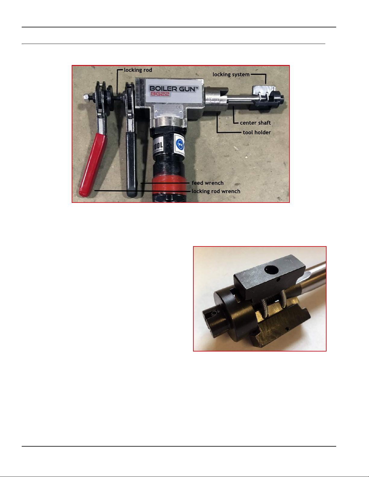
FIGURE 3-1. BG22 BOILER GUN MAIN COMPONENTS
FIGURE 3-2. INSTALLED WEDGE SET WITH EXTENSIONS
Do the following to setup the BG22 Boiler Gun:
3.2.1 Wedge locking system
1. Complete the risk assessment checklist in Table
1-2 on page 5.
2. Position the machine on a solid support for
installation of the wedge set.
3. Measure the ID of the pipe to be machined. Use
the chart on the inside lid of the shipping container to determine the size of the base wedge,
extension set and locking rod.
4. Install the locking rod from the front of the
machine, sliding it through the center shaft.
5. Install the speed wheel/rod wrench on the end
of the locking rod and install the lock nut.
6. Slide the base wedge set over the end plate by
expanding the springs or band spring.
7. Seat the base wedges in the end plate and align
the base wedges with the slots in the center
shaft.
3.2.1.1 Small I.D. wedge locking system
8. If installing wedge extensions, secure three of
the same size range onto the base wedges with
the screws.
The small ID wedge locking system allows the BG22
Boiler Gun to mount on IDs of .500-.625”.
Do the following to setup the small ID wedge locking
system.
1. Position the machine on a solid support for
installation of the wedge system.
2. Follow the instructions for changing the center
shafts, if necessary, in Section 3.2.4.
Page 14 BG22 Boiler Gun Operating Manual
Page 27
3. Install three of the same size wedges in the
FIGURE 3-3. SMALL WEDGE SET
FIGURE 3-4. INSTALLED COLLET SET
slots of the center shaft with the thinner end
facing the threaded portion of the center shaft
and the recess for the band spring facing out.
4. Install the band spring across the recess of the
three wedges to secure.
5. Slide the wedge rod into the center shaft and
turn to advance until the wedges begin to
expand.
6. Install the rod wrench and secure with the two
retaining clips.
3.2.2 Collet locking system
1. Complete the risk assessment checklist in Table
1-2 on page 5.
2. Position the machine on a solid support for
installation of the collet set.
3. Measure the I.D. of the pipe to be machined and
determine the size of the collet set to be used.
4. Slide a locking rod into the center shaft from
the rear of the machine.
5. Thread the required collet set on the end of the
locking rod until the collets begin to engage the
center shaft.
6. Insert a cotter pin through the hole in the locking rod and open the splines to secure.
7. If not present, install the locking rod wrench
and secure with the retaining clips.
3.2.3 Tool holders
The BG22 Boiler Gun can be used with tool holders in
several different sizes.
Do the following to switch between tool holders:
To remove:
1. Loosen the set screw in the body of the tool
holder.
2. The tool holder has an interference fit with the
main gear. Strike the back face of the tool
holder to remove it towards the front of the
machine.
3. The shaft key may come loose from the main
gear during removal. Retain it for reuse.
To install:
1. Check that the set screw in the body of the tool
holder is backed out or remove it completely.
2. Install the shaft key in the key slot on the main
gear.
3. Slide the tool holder onto the main gear, aligning the key way with the shaft key.
4. Tap into place until seated against the shoulder
on the main gear.
5. Reinstall or tighten the set screw in the tool
holder body until secure.
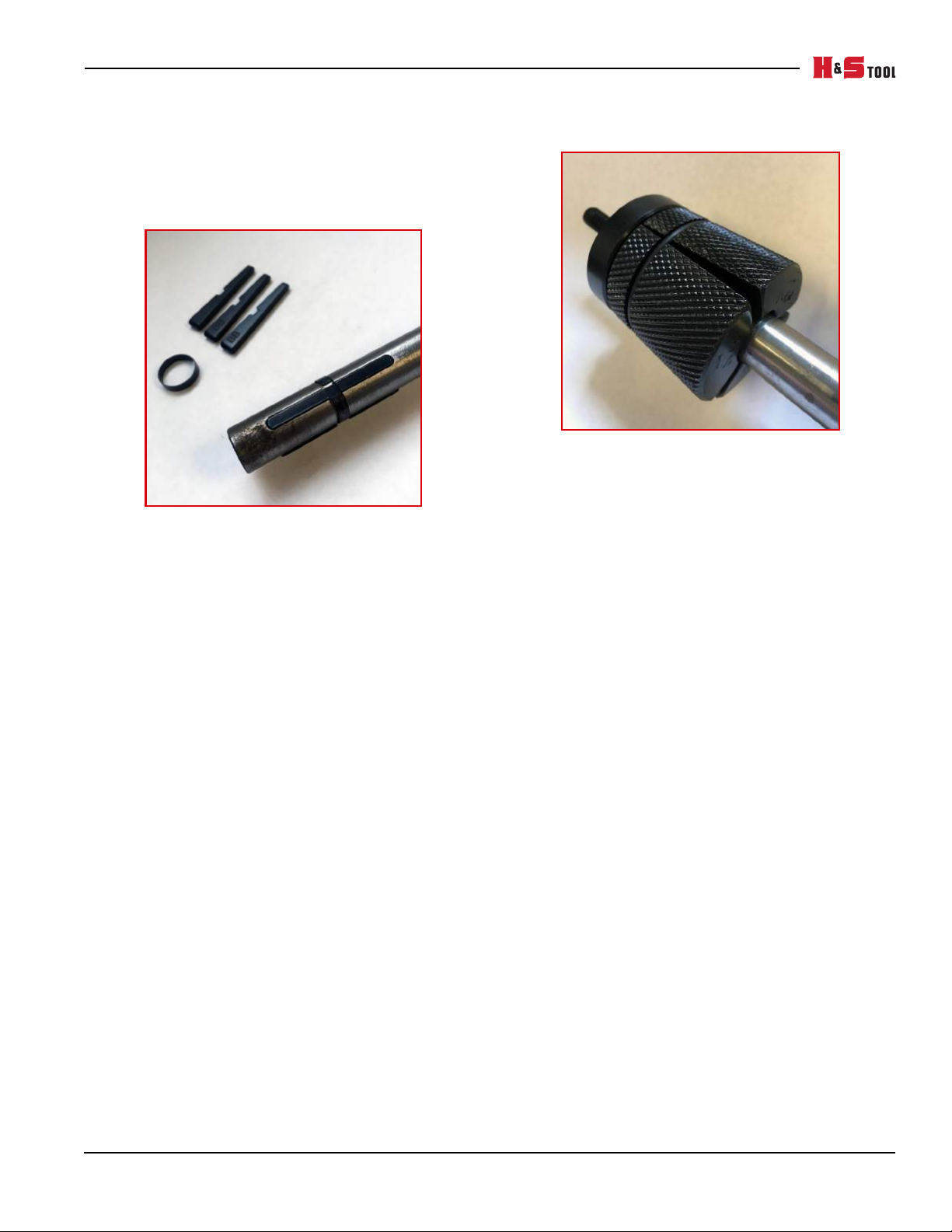
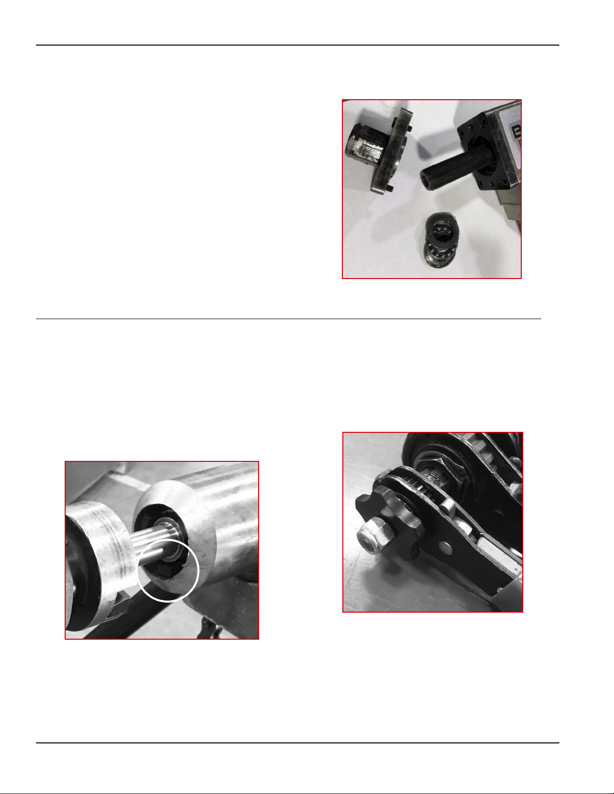
3.2.4 Center shafts
Depending on the application, the center shaft may
need switched out to offer a different size range or
locking system.
Do the following to switch out center shafts:
P/N 100241, Rev. 1 Page 15
Page 28
1. Position the machine on a solid support to
FIGURE 3-5. CHANGING THE CENTER SHAFT
FIGURE 3-6. BG22 BOILER GUN INSTALLED IN WORKPIECE
.50”
FIGURE 3-7. LOCKING ROD WRENCH WITH SPEED WHEEL
change the center shafts.
2. Remove the locking rod, rod wrench and wedge
or collet locking sets.
3. Remove the two screws in the retaining plate
and the lift the retaining plate from the
machine body. Be aware of the thrust bearing
parts during disassembly
4. Remove the feed nut from the center shaft.
5. The center shaft can now be removed through
the front of the machine.
6. Install the other center shaft from the front of
the machine threads first.
7. Replace the thrust bearing parts being mindful
of the order and orientation.
8. Thread the feed nut onto the center shaft until
the center shaft is flush with the back of the
feed nut.
3.3 MACHINE MOUNTING
9. Reinstall the retaining plate and secure with the
two screws.
Do the following to mount the BG22 Boiler Gun on the
workpiece:
1. Insert the mounting system end of the BG22
Boiler Gun into the workpiece until there is
approximately .50” (12.7mm) between the end
of the mounting system and the face of the
workpiece. This will provide enough material
for most procedures.
2. Tighten the mounting system by turning the lock
rod clock-wise using either the rod wrench or
the speed wheel. Once snug, verify that the
mounting system position in the workpiece has
been maintained. Completely tighten the
mounting system using the locking rod wrench.
Page 16 BG22 Boiler Gun Operating Manual
Page 29
WARNING
Check that the mounting system has been
TIP:
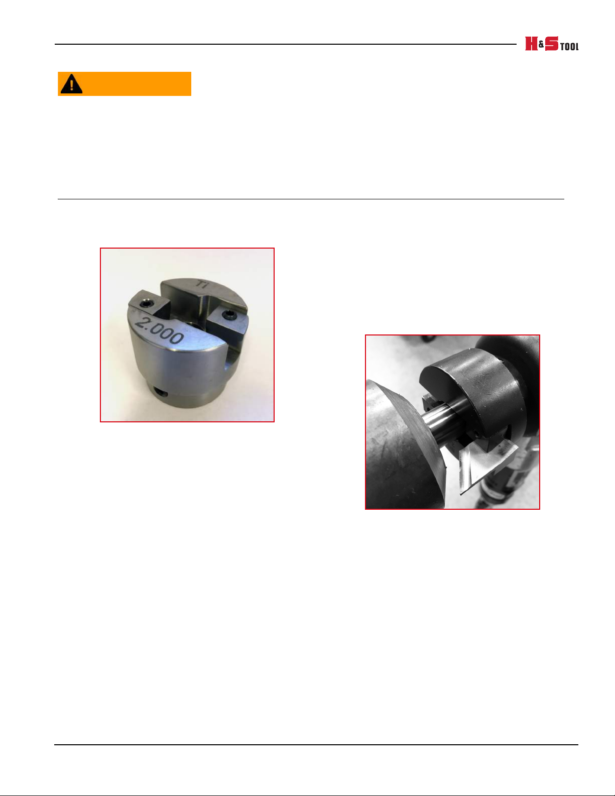
FIGURE 3-8. SLIDING TOOL HOLDER
FIGURE 3-9. CUTTING BIT INSTALLED
fully tightened. After the machine has made
2-3 revolutions during operation, recheck
the mounting system for tightness in the
workpiece. If loose, the machine itself
could rotate causing severe injury to the
operator.
3.4 INSTALLING THE CUTTING TOOLS
While the BG22 Boiler Gun can be
operated with one blade. Smoother
operation on harder materials or thicker
pipe walls will result with the use of
two blades.
Do the following to install the cutting bit(s):
1. Advance the tool holder towards the workpiece
to help with alignment of the cutting bit(s).
2. Loosen the set screws in the blade locks.
3. Slide the cutting bit into the channel with the
beveled cutting edge facing the direction of
rotation.
4. Align the cutting edge of the tool to cut the full
width of the workpiece wall.
5. Tighten the set screw(s) to secure the cutting
bit(s) to the tool holder.
P/N 100241, Rev. 1 Page 17
Page 30

3.5 MOTORS
FIGURE 3-10. UNIVERSAL COUPLER (TOP) AND QUICK
DISCONNECT (BOTTOM)
FIGURE 3-11. MOTOR DIRECTION CONTROL SET TO FORWARD
The BG22 Boiler Gun is powered by either a pneumatic
motor or an electric motor. The following subsections
explain how to set up each for operation.
3.5.1 Pneumatic motor
Do the following to prepare the pneumatic motor for
use (See Section 2.2 for controls):
1. Connect the air supply line to the in-line oiler/
filter end of the air hose assembly with the universal coupler. Secure with the lock pin.
2. Connect the air hose assembly to the pneumatic
drive motor using the quick disconnect coupler.
3.5.2 Electric motor
Do the following to prepare the electric motor for use
(See Section 2.2 for controls):
1. Verify that the direction selector is set to forward.
2. Plug the drive into an OSHA certified power
source or consult a licensed electrician for additional power supply options.
3.5.3 Cordless electric motor
Do the following to prepare the cordless electric motor
for use (See Section 2.2 for controls)
1. Fully charge the battery packs using the battery
charger.
2. Install the battery on the bottom of the motor,
fully locking it into place.
Page 18 BG22 Boiler Gun Operating Manual
Page 31

4 OPERATION
FIGURE 4-1. HAND POSITIONING DURING BOILER GUN OPERATION.
IN THIS CHAPTER:
4.1 PRE-OPERATION CHECKS - - - - - - - - - - - - - - - - - - - - - - - - - - - - - - - - - - - - - - -19
PERATION - - - - - - - - - - - - - - - - - - - - - - - - - - - - - - - - - - - - - - - - - - - - -19
4.2 O
4.2.1 P
NEUMATIC MOTOR - - - - - - - - - - - - - - - - - - - - - - - - - - - - - - - - - - - - - -19
LECTRIC MOTOR - - - - - - - - - - - - - - - - - - - - - - - - - - - - - - - - - - - - - - -20
4.2.2 E
4.1 PRE-OPERATION CHECKS
Do the following checks before operating the machine:
1. Complete the risk assessment checklist in
Table 1-3 on page 5.
2. Check that the work area is clear of non-essential personnel and equipment.
3. Check that the machine control/observation
area will not be in the path of hot flying chips
during machine operation.
4. Check the machine is securely mounted to the
workpiece, according to Section 3.3 on page 14.
4.2 OPERATION
The BG22 Boiler Gun can machine both O.D. and I.D.
bevels and face or shorten pipes. Aside from the use of
different blades, operation is the same for all the
machining processes. See Section 2.2 for controls information.
4.2.1 Pneumatic motor
To operate the BG22 Boiler Gun with the pneumatic
motor do the following:
1. Actuate the motor by unlocking the safety lock
then squeeze and hold the throttle lever.
2. With the other hand turn the feed wrench to
advance the cutting tool into the workpiece.
3. Continue to turn the feed wrench until the
required machining is complete. Base the feed
rate on the motor’s feedback, if the RPMs drop
or the machine stalls slow the feed rate.
4. Once complete, allow the machine to make a
few revolutions without feeding the cutting tool
to clean up the machined surface.
5. Check that hoses and electric cords are routed
and secured to avoid tripping, entanglement,
damage from hot chips, or other damage should
an air hose or connection fail.
6. Check the cutting tool condition and sharpness.
7. On the in-line air lubricator, verify that oil is
present in the sight glass. (See Section 5.3.1)
8. Check that all hand tools are removed from
inside the machine and the work area.
5. Release the throttle lever to stop the machine.
6. Reverse the rotation of the feed wrench to back
the cutting tool away from the workpiece. This
also resets the travel of the machine for the
next workpiece.
7. To remove the BG22 from the workpiece do the
following:
P/N 100241, Rev. 1 Page 19
Page 32

a) Turn off the air supply at the source. Dis-
WARNING
WARNING
FIGURE 4-2. BG22 WITH ELECTRIC MOTOR
connect the air hose assembly from the
machine.
b) Turn the locking wrench to loosen the
locking system from the workpiece.
c) Slide the BG22 straight out from the
workpiece using the body of the machine
to support it’s weight.
Always pick up and move the BG22 Boiler
Gun by body of the machine. Never pick up
the BG22 Boiler Gun by the throttle lever
section of the air motor, actuation of the
motor could occur and lead to severe injury.
Never pick up the BG22 Boiler Gun by the
air hose assembly as it could become
detached and result in injury or damage to
the machine. Do not pick up and move the
machine by either of the wrenches as
damage to the machine could occur.
4.2.2 Electric motor
To operate the BG22 Boiler Gun with the electric motor
do the following:
1. Start the motor by squeezing and holding the
trigger.
2. With the other hand turn the feed wrench to
advance the cutting tool into the workpiece.
3. Continue to turn the feed wrench until the
required machining is complete. Base the feed
rate on the machine’s feedback, if the RPMs
drop or the motor stalls slow the feed rate.
4. Once complete, allow the machine to make a
few revolutions without feeding the cutting tool
to clean up the machined surface.
5. Release the trigger to stop the machine.
6. Reverse the rotation on the feed wrench 2-3
revolutions to back the cutting tool away from
the workpiece.
7. To remove the BG22 from the workpiece do the
following:
a) Unplug or disconnect the power supply
from drive motor. Lock out/tag out where
applicable.
b) Turn the locking wrench to loosen the
locking system from the workpiece.
c) Slide the BG22 straight out from the
workpiece using the body of the machine
to support it’s weight.
Always pick up and move the BG22 Boiler
Gun using the body of the machine or
combination of the center shaft and
machine body. Never pick up the BG22
Boiler Gun by the handle section of the
electric driver, actuation of the motor could
occur and lead to severe injury. Never pick
up the BG22 Boiler Gun by electrical cord as
it could result in damage to the machine.
Do not pick up and move the machine by
the feed wrench as damage to the machine
could occur.
Page 20 BG22 Boiler Gun Operating Manual
Page 33

5 MAINTENANCE
IN THIS CHAPTER:
5.1 MAINTENANCE CHECKLIST - - - - - - - - - - - - - - - - - - - - - - - - - - - - - - - - - - - - - -21
PPROVED LUBRICANTS - - - - - - - - - - - - - - - - - - - - - - - - - - - - - - - - - - - - - - -21
5.2 A
5.3 M
AINTENANCE TASKS - - - - - - - - - - - - - - - - - - - - - - - - - - - - - - - - - - - - - - - - -22
HECKING AND FILLING THE IN-LINE OILER RESERVOIR - - - - - - - - - - - - - - - - - - - - - -22
5.3.1 C
ERVICING THE FILTER ELEMENT - - - - - - - - - - - - - - - - - - - - - - - - - - - - - - - -22
5.3.2 S
5.3.3 A
DJUSTING THE OIL FLOW RATE OF THE IN-LINE OILER - - - - - - - - - - - - - - - - - - - - - -22
OOL HOLDERS - - - - - - - - - - - - - - - - - - - - - - - - - - - - - - - - - - - - - - - -23
5.3.4 T
REASING THE DRIVE AND PINION GEARS - - - - - - - - - - - - - - - - - - - - - - - - - - - -23
5.3.5 G
5.4 T
ROUBLESHOOTING - - - - - - - - - - - - - - - - - - - - - - - - - - - - - - - - - - - - - - - - -23
HE MACHINE ISN’T TURNING - - - - - - - - - - - - - - - - - - - - - - - - - - - - - - - - - -23
5.4.1 T
HE MACHINE ISN’T FEEDING - - - - - - - - - - - - - - - - - - - - - - - - - - - - - - - - - -23
5.4.2 T
5.4.3 T
HE MACHINE IS PERFORMING POORLY - - - - - - - - - - - - - - - - - - - - - - - - - - - - -23
5.1 MAINTENANCE CHECKLIST
Table 5-1 lists maintenance intervals and tasks
TABLE 5-1. MAINTENANCE INTERVALS AND TASKS
Interval Task Reference
Check that oil is present in the sight glass on the in-line oiler, refill as needed. 5.3.1
Before each use
Before and after each use Remove debris, oil, and moisture from machine surfaces. --
Every ten operation cycles Lubricate center shaft threads. --
Check air lines for damage and wear. --
Check the cutting tool for sharpness. Replace as necessary. --
Check and fully charge the batteries on the cordless electric model --
Adjustment of the oil flow rate 5.3.3
Filter element service 5.3.2
5.2 APPROVED LUBRICANTS
H&S recommends using the following lubricants at the
locations indicated.
Failure to use the appropriate lubricants can result in
damage and premature machine wear.
P/N 100241, Rev. 1 Page 21
Page 34

CAUTION
Avoid damage, premature machine wear,
WARNING
and protect your warranty by using only
approved lubricants.
TABLE 5-2. APPROVED LUBRICANTS
Application Area Lubricant
Threads of the center shaft
In-line oiler
Unpainted Surfaces LPS1 or LPS2 N/A 38 @ 25C As required
Drive and pinion
gears
WD-40 or lightweight spray lube
MOBIL ALMO 525 or
10W SAE oil
NOOK PAG-1 grease N/A 113 @ 100C
Biodegradable Lubri-
cant
N/A
N/A 46 @ 40C
Viscosity (cSt) Quantity Frequency
5.3 MAINTENANCE TASKS
Maintenance tasks are described in the following sections.
5.3.1 Checking and filling the in-line
oiler reservoir
Do the following to check and fill the in-line oiler:
1. Check sight glass on the oil reservoir for the
presence of oil.
2. To refill: Remove the cap, fill the reservoir and
replace the cap.
5.3.2 Servicing the filter element
See Figure A-10.
Do the following to service the filter element:
1. Remove the filter nut to access the filter element.
2. Slide the filter element out of the filter housing.
3. Clean the filter element with a solvent and
compressed air.
4. Reassemble the filter and replace the filter nut.
Light coating
applied by
spray
Fill oil lubricator body
Light coating
applied by hand
Daily during machine
use
Each use
Each use, and before
storage
Weekly during machine
use
5.3.3 Adjusting the oil flow rate of the
in-line oiler
To adjust the oil flow rate the machine must
be mounted as if being used. ALL operating
and safety precautions must be taken to
avoid injuries.
Different lubricants and environments may effect the
rate of the in-line oiler.
Do the following to adjust the oil flow rate:
FIGURE 5-1. IN-LINE OILER SIGHT GLASS
Page 22 BG22 Boiler Gun Operating Manual
1. Remove the cap and check the oil level. Refill as
needed.
Page 35

2. Set the oiler valve to ‘3’ as a baseline for the
flow rate.
3. Replace the cap.
4. Mount and setup the machine (see Section 3.2-
3.5)
5. Squeeze and hold the throttle lever to run the
machine.
6. Hold a sheet of white paper approximately 4”
(101mm) in front of the exhaust ports on the
pneumatic motor. If adjusted correctly, there
will be a light splatter of oil on the paper after
a few seconds of operation.
7. If the oil rate needs adjusted, disconnect the
air supply line from the air filter end of the air
hose assembly.
8. Repeat Step 1.
9. The larger the number on the oiler valve the
higher the oil flow rate. Adjust as required.
10. Replace the cap and retest the machine for corrected oil flow rate.
5.4 TROUBLESHOOTING
5.3.4 Tool holders
Do the following to service the tool holders:
1. Monitor and replace as necessary, the o-rings on
the I.D. of the tool holder.
2. Monitor and replace as necessary, the key stock
between the main gear and the tool holders.
5.3.5 Greasing the drive and pinion
gears
Do the following to grease the drive and pinion gears:
1. On either drive type, remove the four screws in
the gearbox adapter.
2. Slide the entire motor, gearbox and gearbox
adapter out of the machine housing.
3. Both the drive and pinions gears are now accessible to be greased.
4. Reverse steps 1 and 2 to reassemble.
This section is intended to help you solve basic machine
performance problems. For serious maintenance or if
you have questions on the following procedures, contact
H&S.
5.4.1 The machine isn’t turning
If the machine is not rotating, check the following:
1. The air supply line is connected and sufficient
air pressure is present (pneumatic motor only).
2. The power source is connected and energized
(electric motor only).
3. The battery in the cordless electric machine is
charged.
5.4.2 The machine isn’t feeding
If the machine isn’t feeding properly, check the following:
1. The center shaft is properly installed in the
machine and .50” (12.7mm) projects through
the back of the feed wrench.
2. The feed wrench is being turned in the wrong
direction.
3. The center shaft has been fed too far into the
machine and need retracted so .50” (12.7mm)
projects through the back of the feed wrench.
5.4.3 The machine is performing poorly
If the machine is performing poorly, check the following:
1. The cutting tool is installed correctly.
2. That the set screw on the tool holder is tight to
the center shaft.
3. The machine is tight to the workpiece.
4. The cutting tool or insert is sharp and has the
correct geometry for the material and type of
cut.
5. Electric motor:
a) The feed direction is set to forward.
b) The battery is charged, cordless model
only.
6. Pneumatic motor:
a) There is oil in the in-line oiler.
b) The air supply to the machine is sufficient
in both quantity and pressure. Optimal
levels are: 90PSI at 38CFM.
P/N 100241, Rev. 1 Page 23
Page 36

This page intentionally left blank
Page 24 BG22 Boiler Gun Operating Manual
Page 37

6 STORAGE AND SHIPPING
IN THIS CHAPTER:
6.1 STORAGE - - - - - - - - - - - - - - - - - - - - - - - - - - - - - - - - - - - - - - - - - - - - - -25
HORT-TERM STORAGE - - - - - - - - - - - - - - - - - - - - - - - - - - - - - - - - - - - -25
6.1.1 S
6.1.2 L
ONG-TERM STORAGE - - - - - - - - - - - - - - - - - - - - - - - - - - - - - - - - - - - - -25
HIPPING - - - - - - - - - - - - - - - - - - - - - - - - - - - - - - - - - - - - - - - - - - - - - -26
6.2 S
ECOMMISSIONING - - - - - - - - - - - - - - - - - - - - - - - - - - - - - - - - - - - - - - - - - -26
6.3 D
6.1 STORAGE
Proper storage of the BG22 Boiler Gun will extend its
usefulness and prevent undue damage.
Store the BG22 Boiler Gun in its original shipping container. Keep all packing materials for repackaging the
machine (see Figure 6-1).
6.1.1 Short-term storage
Do the following for short-term storage (three months
or less):
1. Remove the tooling.
2. Remove hoses.
3. Clean the machine to remove dirt, grease,
metal chips, and moisture.
4. Drain all liquids from the in-line pneumatic
oiler.
5. Spray all unpainted surfaces with LPS-2 to prevent corrosion.
6. Store the BG22 Boiler Gun in its original shipping box (see Figure 6-1).
6.1.2 Long-term storage
Do the following for long-term storage (longer than
three months):
1. Follow the short-term storage instructions, but
use LPS-3 instead of LPS-2.
2. Add a desiccant pouch to the shipping container. Replace according to manufacturer
instructions.
3. Store the shipping container in an environment
out of direct sunlight with temperature < 70ºF
(21ºC) and humidity < 50%.
P/N 100241, Rev. 1 Page 25
Page 38

6.2 SHIPPING
The BG22 Boiler Gun can be reshipped in its original
shipping container, as shown in Figure 6-1.
FIGURE 6-1. BG22 SHIPPING CONTAINER
6.3 DECOMMISSIONING
To decommission the BG22 Boiler Gun prior to disposal,
remove the drive motor and dispose of it separately
from the rest of the machine components. Refer to
Appendix A for component assembly information.
Page 26 BG22 Boiler Gun Operating Manual
Page 39

APPENDIX A ASSEMBLY DRAWINGS
Drawing list
FIGURE A-1. BG22 BOILER GUN PNEUMATIC ASSEMBLY (P/N BG22) - - - - - - - - - - - - - - - - - - - - -28
IGURE A-2. BG22 BOILER GUN ELECTRIC ASSEMBLY (P/N BG22E) - - - - - - - - - - - - - - - - - - - - -29
F
F
IGURE A-3. BG22 BOILER GUN CORDLESS ELECTRIC ASSEMBLY (P/N BG22C) - - - - - - - - - - - - - - -30
IGURE A-4. COLLET COMPONENTS AND COLLETS - - - - - - - - - - - - - - - - - - - - - - - - - - - - -31
F
IGURE A-5. WEDGE SETS AND WEDGE EXTENSIONS - - - - - - - - - - - - - - - - - - - - - - - - - - - -32
F
F
IGURE A-6. WEDGE SET COMPONENTS - - - - - - - - - - - - - - - - - - - - - - - - - - - - - - - - -33
IGURE A-7. SMALL WEDGE SET COMPONENTS - - - - - - - - - - - - - - - - - - - - - - - - - - - - - - -34
F
IGURE A-8. TOOL HOLDERS - - - - - - - - - - - - - - - - - - - - - - - - - - - - - - - - - - - - - - -34
F
F
IGURE A-9. AIR MOTOR ASSEMBLY AND PARTS LIST (P/N CML3488) - - - - - - - - - - - - - - - - - - - -35
IGURE A-10. AIR HOSE ASSEMBLY AND PARTS LIST (P/N HS 50-509) - - - - - - - - - - - - - - - - - - - -36
F
IGURE A-11. ELECTRIC MOTOR ASSEMBLY AND PARTS LIST (P/N EB002615) - - - - - - - - - - - - - - - -37
F
F
IGURE A-12. TOOL KIT - - - - - - - - - - - - - - - - - - - - - - - - - - - - - - - - - - - - - - - - -38
IGURE A-13. SHIPPING CONTAINER - - - - - - - - - - - - - - - - - - - - - - - - - - - - - - - - - - - -38
F
P/N 100241, Rev. 1 Page 27
Page 40

14 4
SOCKET HEAD CAP SCREW
10-24 X 3/8"
5001078
13 1 CENTER SHAFT LOCK TI007822 27 2 SPRING WASHER B002519
12 1 MAIN GEAR TI007821 26 1
DROP SWIVEL
1/2" NPT
95462
11 1
HALF-ROUND KEY
3/16 X 1/2"
9150005 25 1
MALE PLUG
1/2" NPT
DCP2504
10 2 NEEDLE BEARING 9150005 24 1 AIR MOTOR CML3488
9 2 BRONZE THRUST BEARING TI007818 23 1
WOODRUFF KEY
3/16 X 5/8"
9110010
8 1 NEEDLE BEARING 1816 22 2 ROD WRENCH RETAINING RING 9211001
7 1 O-RING 9210216 21 1 ROD WRENCH 23081119900
6 1 HOUSING TI007815 20 1 FEED WRENCH RETAINING RING B000100
5 1 NEEDLE BEARING 9150006 19 1 FEED WRENCH 23259119900
4 1 ADAPTER TI007813 18 2
SOCKET HEAD CAP SCREW
10-32 X 3/8"
4001059
SOCKET HEAD CAP SCREW
3
4
10-24X5
/8"
9020006
171RETAINER PLATE
TI007826
2 1 PINION GEAR TI007811 16 1 FEED NUT B002526
1 1 THRUST BEARING TI007810 15 1 THRUST BEARING B051103
PART
PART
ITEM NO
.
QTY.PART NAME
NUMBER
ITEM NO
.
QTY.PART NAME
NUMBER
Page 28
FIGURE A-1. BG22 BOILER GUN PNEUMATIC ASSEMBLY (P/N BG22)
Page 41

13 1 CENTER SHAFT LOCK TI007822
12 1 MAIN GEAR TI007821 25 1 ELECTRIC MOTOR EB002615
11 1 KEYSTOCK 9110005 24 1 SOCKET HEAD CAP SCREW 5001074
10 2 NEEDLE BEARING 9150005 23 1 ELECTRIC MOTOR ADAPTER 100272
9 2 BRONZE THRUST BEARING TI007818 22 2 ROD WRENCH RETAINER RING 9211001
81NEEDLE BEARING
001816
211ROD WRENCH
23081119900
7 1 O-RING 9210216 20 1 FEED WRENCH RETAINER RING B000100
6 1 HOUSING TI007815 19 1 FEED WRENCH 23259119900
"
5 1 NEEDLE BEARING 9150006 18 4
10-32 X 3/8
SOCKET HEAD CAP SCREW
4001059
4 1 KEYSTOCK 9110011 17 1 RETAINER PLATE TI007826
34
10-24 X 1-1/2"
SOCKET HEAD CAP SCREW
100271 16 1 FEED NUT B002526
2 1 PINION GEAR TI007811 15 1 THRUST BEARING B051103
1 1 DRIVE SHAFT EB002614 14 4
10-24 X 3/8"
SOCKET HEAD CAP SCREW
5001078
ITEM NO. QTY. PART NAME
PART
NUMBER
ITEM NO. QTY. PART NAME
PART
NUMBER
FIGURE A-2. BG22 BOILER GUN ELECTRIC ASSEMBLY (P/N BG22E)
P/N 100241, Rev. 1 Page 29
Page 42

Page 30
FIGURE A-3. BG22 BOILER GUN CORDLESS ELECTRIC ASSEMBLY (P/N BG22C)
Page 43

COLLET 1-3/8" BC1-38 COLLET 2-7/8" BC2-78
COLLET 1-5/16 BC1-516 COLLET 2-3/4" BC2-34
COLLET 1-1/4" BC1-14 COLLET 2-5/8" BC2-58
COLLET 1-3/16" BC1-316 COLLET 2-1/2" BC2-12
COLLET 1-1/8" BC1-18 COLLET 2-3/8" BC2-38
COLLET 1-1/16" BC1-116 COLLET 2-1/4" BC2-14
COLLET 1" BC1 COLLET 2-1/8' BC2-18
COLLET 15/16" BC1516 COLLET 2" BC2
COLLET 7/8" BC78 COLLET 1-7/8" BC1-78
COLLET 3/4" BC34 COLLET 1-3/4" BC1-34
COLLET 13/16" BC1316 COLLET 1-5/8" BC1-58
COLLET 11/16" BC1116 COLLET 1-1/2" BC1-12
COLLET 5/8" BC58 COLLET 1-7/16" BC1-716
PART NAME
PART
NUMBER
PART NAME
PART
NUMBER
4 1 COLLET LOCKING ROD B002550
3 2 RETAINING CLIP 9211001
2 1 COTTER PIN 9231001
1 1 COLLET CENTER SHAFT B002540
ITEM NO. QTY. PART NAME
PART
NUMBER
P/N 100241, Rev. 1 Page 31
FIGURE A-4. COLLET COMPONENTS AND COLLETS
Page 44

10 WEDGE SET B-10 (1.750-1.935") 100225 20 WEDGE EXTENSION SPRING 100246
9 WEDGE SET B-09 (1.625-1.810") 100224 19 WEDGE GUIDE (B-06 - B-14) 100214
8 WEDGE SET B-08 (1.500-1.685") 100223 18 WEDGE BAND SPRING 100245
7 WEDGE SET B-07 (1.375-1.560") 100222 17 WEDGE GUIDE (B-01 - B-05) 100213
6 WEDGE SET B-06 (1.250-1.435") 100221 16
8-32 X 5/16"
SOCKET HEAD CAP SCREW
100270
5 WEDGE SET B-05 (1.125-1.310") 100220 15
3/32 x 3/16"
SPRING PIN
100269
4 WEDGE SET B-04 (1.000-1.185") 100219 14 WEDGE EXTENSION B-14 (2.250-2.435') 100229
3 WEDGE SET B-03 (.875-1.060") 100218 13 WEDGE EXTENSION B-13 (2.125-2.310") 100228
2 WEDGE SET B-02 (.750-.935") 100217 12 WEDGE EXTENSION B-12 (2.000-2.185") 100227
1 WEDGE SET B-01 (.625-.810") 100216 11 WEDGE EXTENSION B-11 (1.875-2.060") 100226
ITEM NO. PART NAME
PART
NUMBER
ITEM NO. PART NAME
PART
NUMBER
Page 32
FIGURE A-5. WEDGE SETS AND WEDGE EXTENSIONS
Page 45

3 1 LOCKING WRENCH 23081119900 6 1 SPRING PIN 9231001
2 1 SPEED WHEEL 100211 5 1 WEDGE CENTER SHAFT 100215
1 1 WEDGE EXPANSION ROD TI007850 4 1 RETAINING CLIP 9211001
ITEM NO. QTY. PART NAME
PART
NUMBER
ITEM NO. QTY. PART NAME
PART
NUMBER
P/N 100241, Rev. 1 Page 33
FIGURE A-6. WEDGE SET COMPONENTS
Page 46

6 1 O-RING TI007815 11 1 SPRING BAND 100245
5 2 DIFFERENTIAL SCREW 9150006 10B 3 BB WEDGE TI007871
4 2 BLADE LOCK TI007813 10A 3 AA WEDGE TI007870
3 2 ROD WRENCH RETAINER RING 9211001 9 1 NEEDLE BEARING 9150007
2 1 EXPANSION ROD TI007851 8 1 SET SCREW 1816
1 1 CENTER SHAFT TI007850 7 1 1.6" TOOL HOLDER 9210216
ITEM NO. QTY. PART NAME
PART
NUMBER
ITEM NO. QTY. PART NAME
PART
NUMBER
5 2 BLADE LOCK 2.0" TI007846
"
42BLADE LOCK 1.6
TI007841
91O-RING
9210114
3 1 TOOL HOLDER 2.5" 9211001 8 1 SET SCREW 1816
2 1 TOOL HOLDER 2.0" TI007851 7 2 DIFFERENTAL SCREW 9170001
1 1 TOOL HOLDER 1.6" TI007843 6 2 BLADE LOCK 2.5" TI007848
ITEM NO. QTY. PART NAME
PART
NUMBER
ITEM NO. QTY. PART NAME
PART
NUMBER
Page 34
FIGURE A-7. SMALL WEDGE SET COMPONENTS
FIGURE A-8. TOOL HOLDERS
Page 47

FIGURE A-9. AIR MOTOR ASSEMBLY AND PARTS LIST (P/N CML3488)
P/N 100241, Rev. 1 Page 35
Page 48

1 FILTER ASSEMBLY HS50-507
8 1 1/2" NIPPLE HS50-517 17 1 SAFETY CLIP HS50-526
7 1 CAP O-RING HS50-516 16 1 RUBBER WASHER HS50-525
6 1 CAP HS50-515 15 1 UNIVERSAL COUPLER HS50-524
5 1 VALVE O-RING HS50-514 14 1 NUT O-RING HS50-523
4 1 OILER VALVE HS50-513 13 1 FILTER NUT HS50-522
3 1 LUBRICATOR BODY HS50-512 12 1 ELEMENT O-RING HS50-521
LUBRICATOR ASSEMBLY HS50-505 11 1 FILTER ELEMENT HS50-520
2 1 QUICK DISCONNECT COUPLER HS50-511 10 1 SPRING HS50-519
1 1 1/2" HOSE WITH FITTINGS HS50-510 9 1 FILTER HOUSING HS50-518
ITEM NO. QTY. PART NAME
PART
NUMBER
ITEM NO. QTY. PART NAME
PART
NUMBER
FIGURE A-10. AIR HOSE ASSEMBLY AND PARTS LIST (P/N HS 50-509)
Page 36
Page 49

FIGURE A-11. ELECTRIC MOTOR ASSEMBLY AND PARTS LIST (P/N EB002615)
P/N 100241, Rev. 1 Page 37
Page 50

FIGURE A-12. TOOL KIT
3 RETAINING CLIP PLIERS SNAP
2 FOLD UP KEY SET 5/64-1/4" 100093
1
1/8" HEX KEY, LONG ARM
(SLIDING TOOL HOLDER ONLY)
ODWR
5/32" HEX KEY, LONG ARM
1
(FIXED TOOL HOLDER ONLY)
05471107
ITEM NO. PART NAME
PART
NUMBER
4 FOAM INSERT, MAIN WITH CUTOUTS 100092
3 FOAM INSERT, BOTTOM 100090
2 FOAM INSERT, LID 100089
1 BG38 SHIPPING CONTAINER 100235
ITEM NO. PART NAME
PART
NUMBER
FIGURE A-13. SHIPPING CONTAINER
Page 38
Page 51

APPENDIX B SDS
SDS list
LPS 1 . . . . . . . . . . . . . . . . . . . . . . . . . . . . . . . 41
LPS 2 . . . . . . . . . . . . . . . . . . . . . . . . . . . . . . . 50
ExxonMobil Mobil Almo 525 . . . . . . . . . . . . . 59
Nook PAG-1 Grease . . . . . . . . . . . . . . . . . . . 68
WD-40 . . . . . . . . . . . . . . . . . . . . . . . . . . . . . . 76
P/N 100241, Rev. 1 Page 39
Page 52

This page intentionally left blank
Page 40
Page 53

S
AFET
Y
DATA SHEET
1.
Iden
t
ification
Product identifier LPS® 1 (Aerosol)
Other means of identification
Part Number
00116
Recommended use
An industrial lubricant designed to displace moisture from mechanical and electrical equipment,
provide light-duty lubrication and short-term rust prevention.
Recommended restrictions
None known.
Manufacturer/Importer/Supplier/Distributor information
Manufacturer
Manufacturer
Company name
LPS Laboratories, a division of Illinois Tool Works, Inc.
Address
4647 Hugh Howell Rd.
Tucker, GA 30084
Country
(U.S.A.)
Tel: +1 770-243-8800
In Case of Emergency
1-800-424-9300 (inside U.S.)
+001 703-527-3887 (outside U.S.)
Website
w
ww.l
p
slabs.com
E-m
ail
sd
s
@
lp
s
labs.com
2. Hazard(s) identification
Category 1Flammable aerosols
Physical hazards
Compressed gasGases under pressure
Category 2Skin corrosion/irritation
Health hazards
Category 1BSensitization, skin
Category 3 narcotic effectsSpecific target organ toxicity, single exposure
Not classified.
Environmental hazards
Not classified.
OSHA defined hazards
Label elements
Si
gnal
word
Da
nger
H
a
zard statement
Extremely flammable aerosol. Contains gas under pressure; may explode if heated. Causes skin
irritation. May cause an allergic skin reaction. May cause drowsiness or dizziness.
Precautionary statement
Prevention
Keep away from heat/sparks/open flames/hot surfaces. - No smoking. Do not spray on an open
flame or other ignition source. Pressurized container: Do not pierce or burn, even after use. Avoid
breathing gas. Wash thoroughly after handling. Use only outdoors or in a well-ventilated area.
Contaminated work clothing must not be allowed out of the workplace. Wear protective gloves.
Response
If on skin: Wash with plenty of water. Take off contaminated clothing and wash before reuse.
Specific treatment (see this label). If skin irritation or rash occurs: Get medical advice/attention. If
inhaled: Remove person to fresh air and keep comfortable for breathing. Call a poison
center/doctor if you feel unwell.
Storage
Store in a well-ventilated place. Keep container tightly closed. Store locked up. Protect from
sunlight. Do not expose to temperatures exceeding 50°C/122°F.
Disposal
Dispose of contents/container in accordance with local/regional/national/international regulations.
Hazard(s) not otherwise
classified (HNOC)
None known.
Supplemental information
None.
1
/ 9
M
a
teria
l name: LPS® 1 (Aerosol)
802 Version #: 01 Issue date: 10-01-2014
SDS US
P/N 100242, Rev. 1
Page 41
Page 54

3
. Composi
t
ion/information on ingredients
Mi
xtures
CAS n
u
mber %Chemical name Common name and synonyms
6
4742-47-8Di
s
t
illate
s
Petroleum, Hydroteated
Light
70 - 80
6
4742-46-7Di
s
t
illate
s
Petroleum Hydrotreated
Med
10 - 20
1
24-38-9Ca
rbon
Diox
i
de
1 - 5
2
6266-58-0So
rbi
t
an tri
o
leate
1 - 3
6
1789-86-4Ca
l
c
ium Sul
f
onate
0.1 - 1
4. First-aid measures
Inhalation
Remove victim to fresh air and keep at rest in a position comfortable for breathing. Call a POISON
CENTER or doctor/physician if you feel unwell.
Skin contact
Remove contaminated clothing immediately and wash skin with soap and water. In case of
eczema or other skin disorders: Seek medical attention and take along these instructions. Wash
contaminated clothing before reuse.
Eye contact
Immediately flush eyes with plenty of water for at least 15 minutes. Remove contact lenses, if
present and easy to do. Continue rinsing. Get medical attention if irritation develops and persists.
Ingestion
In the unlikely event of swallowing contact a physician or poison control center. Rinse mouth. Do
not induce vomiting without advice from poison control center. If vomiting occurs, keep head low
so that stomach content doesn't get into the lungs.
Most important
symptoms/effects, acute and
delayed
May cause drowsiness and dizziness. Headache. Nausea, vomiting. Rash. Skin irritation. May
cause redness and pain. May cause an allergic skin reaction. Dermatitis.
Indication of immediate
medical attention and special
treatment needed
Provide general supportive measures and treat symptomatically. Keep victim under observation.
Symptoms may be delayed.
General information
Ensure that medical personnel are aware of the material(s) involved, and take precautions to
protect themselves. Wash contaminated clothing before reuse.
5. Fire-fighting measures
Suitable extinguishing media
Alcohol resistant foam. Water spray. W ater fog. Dry chemical powder. Dry chemicals. Carbon
dioxide (CO2).
Unsuitable extinguishing
media
Do not use water jet as an extinguisher, as this will spread the fire.
Specific hazards arising from
the chemical
Contents under pressure. Pressurized container may explode when exposed to heat or flame.
During fire, gases hazardous to health may be formed.
Special protective equipment
and precautions for firefighters
Firefighters must use standard protective equipment including flame retardant coat, helmet with
face shield, gloves, rubber boots, and in enclosed spaces, SCBA.
Fire fighting
equipment/instructions
In case of fire: Stop leak if safe to do so. Move containers from fire area if you can do so without
risk. Cool containers exposed to heat with water spray and remove container, if no risk is involved.
Containers should be cooled with water to prevent vapor pressure build up. For massive fire in
cargo area, use unmanned hose holder or monitor nozzles, if possible. If not, withdraw and let fire
burn out.
Specific methods
Use standard firefighting procedures and consider the hazards of other involved materials. Move
containers from fire area if you can do so without risk. Cool containers exposed to flames with
w
ater unti
l
well after the fire is out. In the event
of fire a
n
d/or explosion do not breathe fumes.
G
eneral fi
r
e hazards
Ex
tremely f
l
ammable aerosol. Contents under pressure. Pressurized container may explode when
exposed to heat or flame.
6. Accidental release measures
Personal precautions,
protective equipment and
emergency procedures
Keep unnecessary personnel away. Keep people away from and upwind of spill/leak. Keep out of
low areas. Many gases are heavier than air and will spread along ground and collect in low or
confined areas (sewers, basements, tanks). Wear appropriate protective equipment and clothing
during clean-up. Avoid breathing gas. Do not touch damaged containers or spilled material unless
w
earing ap
p
ropriate protective clothing. Ventilate c
l
osed spa
c
es before entering them. Local
a
uthoritie
s
should be advised if significant spillag
e
s cannot
be contained. Use personal protection
recommended in Section 8 of the SDS.
2
/ 9
Ma
teri
a
l n
a
me: LPS® 1 (Aerosol)
802 Version #: 01 Issue date: 10-01-2014
SDS US
Page 42
Page 55

Methods and materials for
containment and cleaning up
Refer to attached safety data sheets and/or instructions for use. Eliminate all ignition sources (no
smoking, flares, sparks, or flames in immediate area). Keep combustibles (wood, paper, oil, etc.)
away from spilled material. Stop leak if you can do so without risk. Move the cylinder to a safe and
open area if the leak is irreparable. Use water spray to reduce vapors or divert vapor cloud drift.
Isolate area until gas has dispersed. Dike far ahead of spill for later disposal. Scoop up used
absorbent into drums or other appropriate container. Prevent entry into waterways, sewer,
basements or confined areas. Following product recovery, flush area with water. For waste
disposal, see section 13 of the SDS.
Environmental precautions
Avoid discharge into drains, water courses or onto the ground.
7. Handling and storage
Precautions for safe handling
Pressurized container: Do not pierce or burn, even after use. Do not use if spray button is missing
or defective. Do not spray on a naked flame or any other incandescent material. Do not smoke
while using or until sprayed surface is thoroughly dry. Do not cut, weld, solder, drill, grind, or
expose containers to heat, flame, sparks, or other sources of ignition. Do not re-use empty
containers. Avoid breathing gas. Avoid contact with eyes, skin, and clothing. Avoid prolonged
exposure. Use only in well-ventilated areas. Wear appropriate personal protective equipment.
Observe good industrial hygiene practices.
Conditions for safe storage,
including any incompatibilities
Level 1 Aerosol.
Store locked up. Pressurized container. Protect from sunlight and do not expose to temperatures
exceeding 50°C/122 °F. Do not puncture, incinerate or crush. Do not handle or store near an open
flame, heat or other sources of ignition. Store in original tightly closed container. Store in a
well-ventilated place. Keep out of the reach of children. Store away from incompatible materials
(see Section 10 of the SDS).
8. Exposure controls/personal protection
Occupational exposure limits
U.S. - OSHA
ValueComponents
Form
Type
PEL 5 mg/m3 Oil mistDistillates Petroleum,
Hydroteated Light (CAS
64742-47-8)
US. OSHA Table Z-1 Limits for Air Contaminants (29 CFR 1910.1000)
ValueComponents Type
PEL 9000 mg/m3Carbon Dioxide (CAS
124-38-9)
5000 ppm
ACGIH
ValueComponents
Form
Type
TWA 5 mg/m3 Oil mistDistillates Petroleum,
Hydroteated Light (CAS
64742-47-8)
US. ACGIH Threshold Limit Values
ValueComponents Type
STEL 30000 ppmCarbon Dioxide (CAS
124-38-9)
TWA 5000 ppm
US. NIOSH: Pocket Guide to Chemical Hazards
ValueComponents Type
STEL 54000 mg/m3Carbon Dioxide (CAS
124-38-9)
30000 ppm
TWA 9000 mg/m3
5000 ppm
Biological limit values
No biological exposure limits noted for the ingredient(s).
Appropriate engineering
controls
Good general ventilation (typically 10 air changes per hour) should be used. Ventilation rates
should be matched to conditions. If applicable, use process enclosures, local exhaust ventilation,
or other engineering controls to maintain airborne levels below recommended exposure limits. If
exposure limits have not been established, maintain airborne levels to an acceptable level.
3 / 9
Material name: LPS® 1 (Aerosol)
802 Version #: 01 Issue date: 10-01-2014
SDS US
P/N 100242, Rev. 1
Page 43
Page 56

Individual protection measures, such as personal protective equipment
Eye/face protection
Wear safety glasses with side shields (or goggles).
Skin protection
Hand protection
Chemical resistant gloves are recommended.
Other
Avoid contact with the skin. W ear appropriate chemical resistant clothing.
Respiratory protection
When workers are facing concentrations above the exposure limit they must use appropriate
certified respirators.
Thermal hazards
Not applicable.
General hygiene
considerations
Always observe good personal hygiene measures, such as washing after handling the material
and before eating, drinking, and/or smoking. Routinely wash work clothing and protective
equipment to remove contaminants.
9. Physical and chemical properties
Appearance
Liquid.
Physical state
Gas.
Form
Aerosol.
Color
Amber.
Odor
Characteristic.
Odor threshold
Not available.
pH
Not applicable
Melting point/freezing point
< -58 °F (< -50 °C)
Initial boiling point and boiling
range
415.4 °F (213 °C)
Flash point
174.2 °F (79.0 °C) Tag Closed Cup (dispensed liquid)
Evaporation rate
< 0.1 (BuAc = 1)
Flammability (solid, gas)
Flammable gas.
Upper/lower flammability or explosive limits
Flammability limit - lower
(%)
0.6 %
Flammability limit - upper
(%)
7 %
Explosive limit - lower (%)
Not available.
Explosive limit - upper (%)
Not available.
Vapor pressure
< 0.05 mm Hg @ 20°C
Vapor density
> 1 (air = 1)
Relative density
0.79 - 0.81 @ 20°C
Solubility(ies)
Solubility (water)
Not soluble
Partition coefficient
(n-octanol/water)
< 1
Auto-ignition temperature
> 442.4 °F (> 228 °C)
Decomposition temperature
Not established
Viscosity
< 3.8 cSt @ 25°C
Other information
Heat of combustion
Not established
Percent volatile
95 - 96 %
VOC (Weight %)
0.4 % per US State & Federal Consumer Product Regulations
10. Stability and reactivity
Reactivity
The product is stable and non-reactive under normal conditions of use, storage and transport.
Chemical stability
Material is stable under normal conditions.
4 / 9
Material name: LPS® 1 (Aerosol)
802 Version #: 01 Issue date: 10-01-2014
SDS US
Page 44
Page 57

Po
ssib
i
lity of hazardous
re
actio
n
s
Hazardous polymerization does not occur.
Conditions to avoid
Avoid heat, sparks, open flames and other ignition sources. Avoid temperatures exceeding the
flash point. Contact with incompatible materials.
Incompatible materials
Oxidizing agents.
Hazardous decomposition
products
Carbon oxides.
11. Toxicological information
Information on likely routes of exposure
I
nhal
a
tion
Va
pors
h
ave a narcotic effect and may cause headache,
fat
i
gue, dizziness and nausea.
Sk
in c
o
ntact
C
ause
s
skin irritation. May cause an allergic skin re
acti
o
n.
Ey
e co
n
tact
D
irect
contact with eyes may cause temporary irritati
on.
I
nges
ti
on
M
ay b
e
fatal if swallowed and enters airways.
Sy
mptom
s
related to the
physical, chemical and
toxicological characteristics
Symptoms may include stinging, tearing, redness, swelling, and blurred vision. Skin irritation.
Exposure may cause temporary irritation, redness, or discomfort. Defatting of the skin. Rash.
Vapors have a narcotic effect and may cause headache, fatigue, dizziness and nausea. Decrease
i
n mo
t
or functions. Behavioral changes.
I
nform
a
tion on toxicological effects
A
cute
to
xicity
N
arcot
i
c effects. May cause an allergic skin reaction
.
T
est R
e
sultsCo
mpon
e
nts Species
Calcium Sulfonate (CAS 61789-86-4)
LD50 Rabbit
Dermal
Acute
> 2000 mg/kg, 24 Hours
Rat > 2000 mg/kg, 24 Hours
LC50 Rat
Inhalation
> 1.9 mg/l, 4 Hours
LD50 Rat
Oral
10000 - 20000 mg/kg
Distillates Petroleum Hydrotreated Med (CAS 64742-46-7)
LD50 Rabbit
Dermal
Acute
> 2000 mg/kg, 24 Hours
LC50 Rat
Inhalation
7640 mg/m3, 4 Hours
1.72 mg/l, 4 Hours
Distillates Petroleum, Hydroteated Light (CAS 64742-47-8)
LD50 Rabbit
Dermal
Acute
> 2000 mg/kg
> 2000 mg/kg, 24 Hours
LC50 Cat
Inhalation
> 6.4 mg/l, 6 Hours
Rat > 7.5 mg/l, 6 Hours
> 4.3 mg/l, 4 Hours
> 0.1 mg/l, 8 Hours
LD50 Rat
Oral
> 5000 mg/kg
Skin corrosion/irritation
Causes skin irritation.
Serious eye damage/eye
irritation
Direct contact with eyes may cause temporary irritation.
5
/ 9
M
a
t
eri
a
l name: LPS® 1 (Aerosol)
802 Version #: 01 Issue date: 10-01-2014
SDS US
P/N 100242, Rev. 1
Page 45
Page 58

R
espirator
y
or skin sensitization
R
espirator
y
sensitization
N
ot a resp
i
ratory sensitizer.
Sk
in sensi
ti
zation
May cause an allergic skin reaction.
Germ cell mutagenicity
No data available to indicate product or any components present at greater than 0.1% are
mutagenic or genotoxic.
C
arcinoge
n
icity
T
his produ
c
t is not considered to be a carcinogen by
IARC, ACGI
H
, NTP, or OSHA.
OSHA Specifically Regulated Substances (29 CFR 1910.1001-1050)
Not listed.
Reproductive toxicity
This product is not expected to cause reproductive or developmental effects.
Specific target organ toxicity single exposure
Narcotic effects.
Specific target organ toxicity repeated exposure
Based on available data, the classification criteria are not met.
A
spiration
hazard
N
ot likel
y
, due to the form of the product.
C
hronic e
ffe
cts
Pro
longed i
n
halation may be harmful.
12
. Ecologi
c
al information
Ecotoxicity
Harmful to aquatic life with long lasting effects.
Components Test ResultsSpecies
D
istillat
e
s Petroleum, Hydroteated Light (CAS 64742-4
7-8)
Aquatic
L
C
50Fish 2.9 mg/l, 96 hoursRainbow trout,donaldson trout
(Oncorhynchus mykiss)
Persistence and degradability
Not inherently biodegradable.
Bioaccumulative potential
Not available.
Pa
rtition co
e
fficient n-octanol / water (log Kow)
L
PS® 1 (Aeroso
l
) <
1
Mobility
i
n soil
No data available.
O
ther adve
r
se effects
N
one know
n
.
13
. Disposa
l
considerations
Disposal instructions
Consult authorities before disposal. Contents under pressure. Do not puncture, incinerate or crush.
Dispose of contents/container in accordance with local/regional/national/international regulations.
Local disposal regulations
Dispose in accordance with all applicable regulations.
Hazardous waste code
D003: Waste Reactive material
Waste from residues / unused
products
Dispose of in accordance with local regulations. Empty containers or liners may retain some
product residues. This material and its container must be disposed of in a safe manner (see:
Disposal instructions).
Contaminated packaging
Empty containers should be taken to an approved waste handling site for recycling or disposal.
Since emptied containers may retain product residue, follow label warnings even after container is
emptied. Do not re-use empty containers.
14. Transport information
DOT
UN1950
UN number
Aerosols, flammable
UN proper shipping name
2.1
Class
Transport hazard class(es)
-
Subsidiary risk
2.1
Label(s)
Not applicable.
Packing group
No
Marine pollutant
Environmental hazards
Read safety instructions, SDS and emergency procedures before handling.
Special precautions for user
N82
Special provisions
306
Packaging exceptions
6
/ 9
Ma
teri
a
l n
a
me: LPS® 1 (Aerosol)
802 Version #: 01 Issue date: 10-01-2014
SDS US
Page 46
Page 59

N
one
Pa
ckaging non bulk
None
Packaging bulk
IATA
UN1950
UN number
Aerosols, flammable
UN proper shipping name
2.1
Class
Transport hazard class(es)
-
Subsidiary risk
Not applicable.
Packing group
No
Environmental hazards
10L
ERG Code
Read safety instructions, SDS and emergency procedures before handling.
Special precautions for user
Allowed.
Passenger and cargo
aircraft
Other information
Allowed.
Cargo aircraft only
IMDG
UN1950
UN number
AEROSOLS, Flammable
UN proper shipping name
2.1
Class
Transport hazard class(es)
-
Subsidiary risk
2.1
Label(s)
Not applicable.
Packing group
No
Marine pollutant
Environmental hazards
F-D, S-U
EmS
Read safety instructions, SDS and emergency procedures before handling.
Special precautions for user
This substance/mixture is not intended to be transported in bulk.
Transport in bulk according to
Annex II of MARPOL 73/78 and
the IBC Code
DOT
I
ATA
;
IMDG
1
5. R
e
gulatory information
US
fede
r
al regulations
This product is a "Hazardous Chemical" as defined by the OSHA Hazard Communication
Standard, 29 CFR 1910.1200.
All components are on the U.S. EPA TSCA Inventory List.
TSCA Section 12(b) Export Notification (40 CFR 707, Subpt. D)
Not regulated.
7 / 9
M
a
ter
i
al name: LPS® 1 (Aerosol)
802 Version #: 01 Issue date: 10-01-2014
SDS US
P/N 100242, Rev. 1
Page 47
Page 60

CERCLA Hazardous Substance List (40 CFR 302.4)
Not listed.
SARA 304 Emergency release notification
Not regulated.
OSHA Specifically Regulated Substances (29 CFR 1910.1001-1050)
Not listed.
Superfund Amendments and Reauthorization Act of 1986 (SARA)
Hazard categories
Immediate Hazard - Yes
Delayed Hazard - No
Fire Hazard - Yes
Pressure Hazard - Yes
Reactivity Hazard - No
SARA 302 Extremely hazardous substance
Not listed.
SARA 311/312 Hazardous
chemical
Yes
SARA 313 (TRI reporting)
Not regulated.
Other federal regulations
Clean Air Act (CAA) Section 112 Hazardous Air Pollutants (HAPs) List
Not regulated.
Clean Air Act (CAA) Section 112(r) Accidental Release Prevention (40 CFR 68.130)
Not regulated.
Safe Drinking Water Act
(SDWA)
Not regulated.
US state regulations
US. California Controlled Substances. CA Department of Justice (California Health and Safety Code Section 11100)
Not listed.
US. Massachusetts RTK - Substance List
Carbon Dioxide (CAS 124-38-9)
US. New Jersey Worker and Community Right-to-Know Act
Carbon Dioxide (CAS 124-38-9)
US. Pennsylvania Worker and Community Right-to-Know Law
Carbon Dioxide (CAS 124-38-9)
US. Rhode Island RTK
Not regulated.
US. California Proposition 65
California Safe Drinking W ater and Toxic Enforcement Act of 1986 (Proposition 65): This material is not known to contain
any chemicals currently listed as carcinogens or reproductive toxins.
International Inventories
Country(s) or region Inventory name On inventory (yes/no)*
YesAustralia Australian Inventory of Chemical Substances (AICS)
YesCanada Domestic Substances List (DSL)
NoCanada Non-Domestic Substances List (NDSL)
NoChina Inventory of Existing Chemical Substances in China (IECSC)
YesEurope European Inventory of Existing Commercial Chemical
Substances (EINECS)
NoEurope European List of Notified Chemical Substances (ELINCS)
NoJapan Inventory of Existing and New Chemical Substances (ENCS)
YesKorea Existing Chemicals List (ECL)
NoNew Zealand New Zealand Inventory
YesPhilippines Philippine Inventory of Chemicals and Chemical Substances
(PICCS)
8 / 9
Material name: LPS® 1 (Aerosol)
802 Version #: 01 Issue date: 10-01-2014
SDS US
Page 48
Page 61

Country(s) or region Inventory name On inventory (yes/no)*
YesUnited States & Puerto Rico Toxic Substances Control Act (TSCA) Inventory
*A "Yes" indicates that all components of this product comply with the inventory requirements administered by the governing country(s)
A "No" indicates that one or more components of the product are not listed or exempt from listing on the inventory administered by the governing
country(s).
16. Other information, including date of preparation or last revision
Issue date
10-01-2014
Version #
01
Disclaimer
LPS Laboratories cannot anticipate all conditions under which this information and its product, or
the products of other manufacturers in combination with its product, may be used. It is the user’s
responsibility to ensure safe conditions for handling, storage and disposal of the product, and to
assume liability for loss, injury, damage or expense due to improper use. The information provided
in this Safety Data Sheet is correct to the best of our knowledge, information and belief at the date
of its publication. The information given is designed only as a guidance for safe handling, use,
processing, storage, transportation, disposal and release and is not to be considered a warranty or
quality specification. The information relates only to the specific material designated and may not
be valid for such material used in combination with any other materials or in any process, unless
specified in the text.
9 / 9
Material name: LPS® 1 (Aerosol)
802 Version #: 01 Issue date: 10-01-2014
SDS US
P/N 100242, Rev. 1
Page 49
Page 62

SAFETY DATA SHEET
1. Identification
Product identifier LPS® 2 (Aerosol)
Other means of identification
Part Number
00216
Recommended use
An industrial lubricant designed to displace moisture from equipment, provide heavy-duty
lubrication and rust prevention.
Recommended restrictions
None known.
Manufacturer/Importer/Supplier/Distributor information
Manufacturer
Manufacturer
Company name
LPS Laboratories, a division of Illinois Tool Works, Inc.
Address
4647 Hugh Howell Rd.
Tucker, GA 30084
Country
(U.S.A.)
Tel: +1 770-243-8800
In Case of Emergency
1-800-424-9300 (inside U.S.)
+001 703-527-3887 (outside U.S.)
Website
www.lpslabs.com
E-mail
sds@lpslabs.com
2. Hazard(s) identification
Category 1Flammable aerosols
Physical hazards
Compressed gasGases under pressure
Category 2Skin corrosion/irritation
Health hazards
Category 2ASerious eye damage/eye irritation
Category 3 narcotic effectsSpecific target organ toxicity, single exposure
Not classified.
Environmental hazards
Not classified.
OSHA defined hazards
Label elements
Signal word
Danger
Hazard statement
Extremely flammable aerosol. Contains gas under pressure; may explode if heated. Causes skin
irritation. Causes serious eye irritation. May cause drowsiness or dizziness.
Precautionary statement
Prevention
Keep away from heat/sparks/open flames/hot surfaces. - No smoking. Do not spray on an open
flame or other ignition source. Pressurized container: Do not pierce or burn, even after use. Avoid
breathing gas. Wash thoroughly after handling. Use only outdoors or in a well-ventilated area.
Wear protective gloves. Wear eye/face protection.
Response
If on skin: Wash with plenty of water. If inhaled: Remove person to fresh air and keep comfortable
for breathing. If in eyes: Rinse cautiously with water for several minutes. Remove contact lenses,
if present and easy to do. Continue rinsing. Call a poison center/doctor if you feel unwell. Specific
treatment (see this label). If skin irritation occurs: Get medical advice/attention. If eye irritation
persists: Get medical advice/attention. Take off contaminated clothing and wash before reuse.
Storage
Store in a well-ventilated place. Keep container tightly closed. Store locked up. Protect from
sunlight. Do not expose to temperatures exceeding 50°C/122°F.
Disposal
Dispose of contents/container in accordance with local/regional/national/international regulations.
Hazard(s) not otherwise
classified (HNOC)
None known.
1 / 9
Material name: LPS® 2 (Aerosol)
729 Version #: 01 Issue date: 09-22-2014
SDS US
Page 50
Page 63

Supplemental information
None.
3. Composition/information on ingredients
Mixtures
CAS number %Chemical name Common name and synonyms
64742-47-8Distillates Petroleum, Hydroteated
Light
70 - 80
64742-52-5Petroleum Oil
10 - 20
124-38-9Carbon Dioxide
1 - 5
4. First-aid measures
Inhalation
Remove victim to fresh air and keep at rest in a position comfortable for breathing. For breathing
difficulties, oxygen may be necessary. Call a physician if symptoms develop or persist.
Skin contact
Wash off with soap and water. Get medical attention if irritation develops and persists.
Eye contact
Immediately flush eyes with plenty of water for at least 15 minutes. Remove contact lenses, if
present and easy to do. Continue rinsing. Get medical attention if irritation develops and persists.
Ingestion
Call a physician or poison control center immediately. Only induce vomiting at the instruction of
medical personnel. Never give anything by mouth to an unconscious person. If vomiting occurs,
keep head low so that stomach content doesn't get into the lungs.
Most important
symptoms/effects, acute and
delayed
Dermatitis. Rash. Symptoms of overexposure may be headache, dizziness, tiredness, nausea and
vomiting. Skin irritation. May cause redness and pain.
Indication of immediate
medical attention and special
treatment needed
Provide general supportive measures and treat symptomatically.
General information
Ensure that medical personnel are aware of the material(s) involved, and take precautions to
protect themselves. Call a POISON CENTER or doctor/physician if you feel unwell.
5. Fire-fighting measures
Suitable extinguishing media
Powder. Alcohol resistant foam. Water. W ater spray. Dry chemicals. Carbon dioxide (CO2).
Unsuitable extinguishing
media
Do not use water jet as an extinguisher, as this will spread the fire.
Specific hazards arising from
the chemical
Contents under pressure. Pressurized container may explode when exposed to heat or flame.
Special protective equipment
and precautions for firefighters
Firefighters must use standard protective equipment including flame retardant coat, helmet with
face shield, gloves, rubber boots, and in enclosed spaces, SCBA.
Fire fighting
equipment/instructions
In case of fire: Stop leak if safe to do so. Move containers from fire area if you can do so without
risk. Cool containers exposed to heat with water spray and remove container, if no risk is involved.
Containers should be cooled with water to prevent vapor pressure build up. For massive fire in
cargo area, use unmanned hose holder or monitor nozzles, if possible. If not, withdraw and let fire
burn out.
Specific methods
Use standard firefighting procedures and consider the hazards of other involved materials. Move
containers from fire area if you can do so without risk. Cool containers exposed to flames with
water until well after the fire is out. In the event of fire and/or explosion do not breathe fumes.
General fire hazards
Extremely flammable aerosol.
6. Accidental release measures
Personal precautions,
protective equipment and
emergency procedures
Keep unnecessary personnel away. Keep people away from and upwind of spill/leak. Keep out of
low areas. Wear appropriate protective equipment and clothing during clean-up. Do not touch
damaged containers or spilled material unless wearing appropriate protective clothing. Ventilate
closed spaces before entering them. Local authorities should be advised if significant spillages
cannot be contained. Use personal protection recommended in Section 8 of the SDS.
Methods and materials for
containment and cleaning up
Refer to attached safety data sheets and/or instructions for use. Eliminate all ignition sources (no
smoking, flares, sparks, or flames in immediate area). Keep combustibles (wood, paper, oil, etc.)
away from spilled material. Stop leak if you can do so without risk. Move the cylinder to a safe and
open area if the leak is irreparable. Isolate area until gas has dispersed. Use water spray to reduce
vapors or divert vapor cloud drift. Scoop up used absorbent into drums or other appropriate
container. Prevent entry into waterways, sewer, basements or confined areas. Following product
recovery, flush area with water. For waste disposal, see section 13 of the SDS.
Environmental precautions
Avoid discharge into drains, water courses or onto the ground.
2 / 9
Material name: LPS® 2 (Aerosol)
729 Version #: 01 Issue date: 09-22-2014
SDS US
P/N 100242, Rev. 1
Page 51
Page 64

7. Handling and storage
Precautions for safe handling
Pressurized container: Do not pierce or burn, even after use. Do not use if spray button is missing
or defective. Do not spray on a naked flame or any other incandescent material. Do not smoke
while using or until sprayed surface is thoroughly dry. Do not cut, weld, solder, drill, grind, or
expose containers to heat, flame, sparks, or other sources of ignition. All equipment used when
handling the product must be grounded. Do not re-use empty containers. Avoid prolonged or
repeated contact with skin. Avoid prolonged exposure. Use only in well-ventilated areas. Wear
appropriate personal protective equipment. Wash hands thoroughly after handling. Observe good
industrial hygiene practices.
Conditions for safe storage,
including any incompatibilities
Level 3 Aerosol.
Store locked up. Pressurized container. Protect from sunlight and do not expose to temperatures
exceeding 50°C/122 °F. Do not puncture, incinerate or crush. Do not handle or store near an open
flame, heat or other sources of ignition. This material can accumulate static charge which may
cause spark and become an ignition source. Prevent electrostatic charge build-up by using
common bonding and grounding techniques. Store in original tightly closed container. Store in a
well-ventilated place. Store away from incompatible materials (see Section 10 of the SDS). Keep
out of the reach of children.
8. Exposure controls/personal protection
Occupational exposure limits
U.S. - OSHA
ValueComponents
Form
Type
PEL 5 mg/m3 Oil mistDistillates Petroleum,
Hydroteated Light (CAS
64742-47-8)
PEL 5 mg/m3 Oil mistPetroleum Oil (CAS
64742-52-5)
US. OSHA Table Z-1 Limits for Air Contaminants (29 CFR 1910.1000)
ValueComponents Type
PEL 9000 mg/m3Carbon Dioxide (CAS
124-38-9)
5000 ppm
ACGIH
ValueComponents
Form
Type
TWA 5 mg/m3 Oil mistDistillates Petroleum,
Hydroteated Light (CAS
64742-47-8)
TWA 5 mg/m3 Oil mistPetroleum Oil (CAS
64742-52-5)
US. ACGIH Threshold Limit Values
ValueComponents Type
STEL 30000 ppmCarbon Dioxide (CAS
124-38-9)
TWA 5000 ppm
US. NIOSH: Pocket Guide to Chemical Hazards
ValueComponents Type
STEL 54000 mg/m3Carbon Dioxide (CAS
124-38-9)
30000 ppm
TWA 9000 mg/m3
5000 ppm
Biological limit values
No biological exposure limits noted for the ingredient(s).
Appropriate engineering
controls
Good general ventilation (typically 10 air changes per hour) should be used. Ventilation rates
should be matched to conditions. If applicable, use process enclosures, local exhaust ventilation,
or other engineering controls to maintain airborne levels below recommended exposure limits. If
exposure limits have not been established, maintain airborne levels to an acceptable level. Eye
wash facilities and emergency shower must be available when handling this product.
Individual protection measures, such as personal protective equipment
Eye/face protection
Wear safety glasses with side shields (or goggles).
3 / 9
Material name: LPS® 2 (Aerosol)
729 Version #: 01 Issue date: 09-22-2014
SDS US
Page 52
Page 65

Skin protection
Hand protection
Chemical resistant gloves are recommended.
Other
Wear suitable protective clothing.
Respiratory protection
In case of insufficient ventilation, wear suitable respiratory equipment.
Thermal hazards
Not applicable.
General hygiene
considerations
When using, do not eat, drink or smoke. Always observe good personal hygiene measures, such
as washing after handling the material and before eating, drinking, and/or smoking. Routinely
wash work clothing and protective equipment to remove contaminants.
9. Physical and chemical properties
Appearance
Liquid.
Physical state
Gas.
Form
Aerosol.
Color
Brown
Odor
Slight petroleum odor, Cherry
Odor threshold
Not established
pH
Not applicable
Melting point/freezing point
< -58 °F (< -50 °C)
Initial boiling point and boiling
range
383 °F (195 °C) @ 101 kPa
Flash point
174.2 °F (79.0 °C) Tag Closed Cup (dispensed liquid)
Evaporation rate
< 0.1 BuAc
Flammability (solid, gas)
Flammable gas.
Upper/lower flammability or explosive limits
Flammability limit - lower
(%)
0.6 %
Flammability limit - upper
(%)
7 %
Explosive limit - lower (%)
Not available.
Explosive limit - upper (%)
Not available.
Vapor pressure
< 0.05 mm Hg @ 20ºC (dispensed liquid)
Vapor density
4.7 (air = 1)
Relative density
Not available.
Solubility(ies)
Solubility (water)
< 3 %
Partition coefficient
(n-octanol/water)
< 1
Auto-ignition temperature
> 442.4 °F (> 228 °C)
Decomposition temperature
Not established
Viscosity
< 7 cSt
Viscosity temperature
77 °F (25 °C)
Other information
Heat of combustion
> 30 kJ/g
Percent volatile
92 - 95 %
Specific gravity
0.82 - 0.86 @ 20°C
10. Stability and reactivity
Reactivity
The product is stable and non-reactive under normal conditions of use, storage and transport.
Chemical stability
Material is stable under normal conditions.
Possibility of hazardous
reactions
Hazardous polymerization does not occur.
Conditions to avoid
Avoid heat, sparks, open flames and other ignition sources. Avoid temperatures exceeding the
flash point. Contact with incompatible materials.
4 / 9
Material name: LPS® 2 (Aerosol)
729 Version #: 01 Issue date: 09-22-2014
SDS US
P/N 100242, Rev. 1
Page 53
Page 66

Incompatible materials
Strong oxidizing agents.
Hazardous decomposition
products
Carbon oxides.
11. Toxicological information
Information on likely routes of exposure
Inhalation
Vapors have a narcotic effect and may cause headache, fatigue, dizziness and nausea.
Skin contact
Causes skin irritation.
Eye contact
Causes serious eye irritation.
Ingestion
May cause discomfort if swallowed.
Symptoms related to the
physical, chemical and
toxicological characteristics
Irritating to eyes, respiratory system and skin. Symptoms may include stinging, tearing, redness,
swelling, and blurred vision. Exposure may cause temporary irritation, redness, or discomfort.
Vapors have a narcotic effect and may cause headache, fatigue, dizziness and nausea.
Information on toxicological effects
Acute toxicity
Narcotic effects.
Test ResultsComponents Species
Distillates Petroleum, Hydroteated Light (CAS 64742-47-8)
LD50 Rabbit
Dermal
Acute
> 2000 mg/kg
> 2000 mg/kg, 24 Hours
LC50 Cat
Inhalation
> 6.4 mg/l, 6 Hours
Rat > 7.5 mg/l, 6 Hours
> 4.3 mg/l, 4 Hours
> 0.1 mg/l, 8 Hours
LD50 Rat
Oral
> 5000 mg/kg
Petroleum Oil (CAS 64742-52-5)
LD50 Rabbit
Dermal
Acute
> 2000 mg/kg
> 2000 mg/kg, 24 Hours
LC50 Rat
Inhalation
2.18 mg/l, 4 Hours
LD50 Rat
Oral
5000 mg/kg
Skin corrosion/irritation
Causes skin irritation.
Serious eye damage/eye
irritation
Causes serious eye irritation.
Respiratory or skin sensitization
Respiratory sensitization
Not a respiratory sensitizer.
Skin sensitization
This product is not expected to cause skin sensitization.
Germ cell mutagenicity
No data available to indicate product or any components present at greater than 0.1% are
mutagenic or genotoxic.
Carcinogenicity
This product is not considered to be a carcinogen by IARC, ACGIH, NTP, or OSHA.
OSHA Specifically Regulated Substances (29 CFR 1910.1001-1050)
Not listed.
Reproductive toxicity
This product is not expected to cause reproductive or developmental effects.
Specific target organ toxicity single exposure
Narcotic effects.
5 / 9
Material name: LPS® 2 (Aerosol)
729 Version #: 01 Issue date: 09-22-2014
SDS US
Page 54
Page 67

Specific target organ toxicity repeated exposure
Based on available data, the classification criteria are not met.
Aspiration hazard
Not likely, due to the form of the product.
Chronic effects
Prolonged inhalation may be harmful.
12. Ecological information
Ecotoxicity
The product is not classified as environmentally hazardous. However, this does not exclude the
possibility that large or frequent spills can have a harmful or damaging effect on the environment.
Components Test ResultsSpecies
Distillates Petroleum, Hydroteated Light (CAS 64742-47-8)
Aquatic
LC50Fish 2.9 mg/l, 96 hoursRainbow trout,donaldson trout
(Oncorhynchus mykiss)
Persistence and degradability
Not inherently biodegradable.
Bioaccumulative potential
Not available.
Partition coefficient n-octanol / water (log Kow)
LPS® 2 (Aerosol) < 1
Mobility in soil
No data available.
Other adverse effects
None known.
13. Disposal considerations
Disposal instructions
Consult authorities before disposal. Contents under pressure. Do not puncture, incinerate or crush.
Dispose of contents/container in accordance with local/regional/national/international regulations.
Local disposal regulations
Dispose in accordance with all applicable regulations.
Hazardous waste code
D003: Waste Reactive material
Waste from residues / unused
products
Dispose of in accordance with local regulations. Empty containers or liners may retain some
product residues. This material and its container must be disposed of in a safe manner (see:
Disposal instructions).
Contaminated packaging
Empty containers should be taken to an approved waste handling site for recycling or disposal.
Since emptied containers may retain product residue, follow label warnings even after container is
emptied. Do not re-use empty containers.
14. Transport information
DOT
UN1950
UN number
Aerosols, flammable
UN proper shipping name
2.1
Class
Transport hazard class(es)
-
Subsidiary risk
2.1
Label(s)
Not applicable.
Packing group
No
Marine pollutant
Environmental hazards
Read safety instructions, SDS and emergency procedures before handling. Read safety
instructions, SDS and emergency procedures before handling.
Special precautions for user
306
Packaging exceptions
None
Packaging non bulk
None
Packaging bulk
IATA
UN1950
UN number
Aerosols, flammable
UN proper shipping name
2.1
Class
Transport hazard class(es)
-
Subsidiary risk
2.1
Label(s)
Not applicable.
Packing group
No.
Environmental hazards
10L
ERG Code
6 / 9
Material name: LPS® 2 (Aerosol)
729 Version #: 01 Issue date: 09-22-2014
SDS US
P/N 100242, Rev. 1
Page 55
Page 68

Read safety instructions, SDS and emergency procedures before handling. Read safety
instructions, SDS and emergency procedures before handling.
Special precautions for user
Allowed.
Passenger and cargo
aircraft
Other information
Allowed.
Cargo aircraft only
IMDG
UN1950
UN number
AEROSOLS, flammable
UN proper shipping name
2.1
Class
Transport hazard class(es)
-
Subsidiary risk
2.1
Label(s)
Not applicable.
Packing group
No
Marine pollutant
Environmental hazards
Not available.
EmS
Read safety instructions, SDS and emergency procedures before handling. Read safety
instructions, SDS and emergency procedures before handling.
Special precautions for user
Not applicable.
Transport in bulk according to
Annex II of MARPOL 73/78 and
the IBC Code
DOT
IATA; IMDG
15. Regulatory information
US federal regulations
This product is a "Hazardous Chemical" as defined by the OSHA Hazard Communication
Standard, 29 CFR 1910.1200.
TSCA Section 12(b) Export Notification (40 CFR 707, Subpt. D)
Not regulated.
CERCLA Hazardous Substance List (40 CFR 302.4)
Not listed.
SARA 304 Emergency release notification
Not regulated.
OSHA Specifically Regulated Substances (29 CFR 1910.1001-1050)
Not listed.
7 / 9
Material name: LPS® 2 (Aerosol)
729 Version #: 01 Issue date: 09-22-2014
SDS US
Page 56
Page 69

Superfund Amendments and Reauthorization Act of 1986 (SARA)
Hazard categories
Immediate Hazard - Yes
Delayed Hazard - No
Fire Hazard - Yes
Pressure Hazard - Yes
Reactivity Hazard - No
SARA 302 Extremely hazardous substance
Not listed.
SARA 311/312 Hazardous
chemical
Yes
SARA 313 (TRI reporting)
Not regulated.
Other federal regulations
Clean Air Act (CAA) Section 112 Hazardous Air Pollutants (HAPs) List
Not regulated.
Clean Air Act (CAA) Section 112(r) Accidental Release Prevention (40 CFR 68.130)
Not regulated.
Safe Drinking Water Act
(SDWA)
Not regulated.
US state regulations
US. California Controlled Substances. CA Department of Justice (California Health and Safety Code Section 11100)
Not listed.
US. Massachusetts RTK - Substance List
Carbon Dioxide (CAS 124-38-9)
US. New Jersey Worker and Community Right-to-Know Act
Carbon Dioxide (CAS 124-38-9)
US. Pennsylvania Worker and Community Right-to-Know Law
Carbon Dioxide (CAS 124-38-9)
US. Rhode Island RTK
Not regulated.
US. California Proposition 65
California Safe Drinking W ater and Toxic Enforcement Act of 1986 (Proposition 65): This material is not known to contain
any chemicals currently listed as carcinogens or reproductive toxins.
International Inventories
Country(s) or region Inventory name On inventory (yes/no)*
YesAustralia Australian Inventory of Chemical Substances (AICS)
YesCanada Domestic Substances List (DSL)
NoCanada Non-Domestic Substances List (NDSL)
NoChina Inventory of Existing Chemical Substances in China (IECSC)
YesEurope European Inventory of Existing Commercial Chemical
Substances (EINECS)
NoEurope European List of Notified Chemical Substances (ELINCS)
NoJapan Inventory of Existing and New Chemical Substances (ENCS)
YesKorea Existing Chemicals List (ECL)
NoNew Zealand New Zealand Inventory
YesPhilippines Philippine Inventory of Chemicals and Chemical Substances
(PICCS)
YesUnited States & Puerto Rico Toxic Substances Control Act (TSCA) Inventory
*A "Yes" indicates that all components of this product comply with the inventory requirements administered by the governing country(s)
A "No" indicates that one or more components of the product are not listed or exempt from listing on the inventory administered by the governing
country(s).
16. Other information, including date of preparation or last revision
Issue date
09-22-2014
Version #
01
8 / 9
Material name: LPS® 2 (Aerosol)
729 Version #: 01 Issue date: 09-22-2014
SDS US
P/N 100242, Rev. 1
Page 57
Page 70

Disclaimer
The information provided in this Safety Data Sheet is correct to the best of our knowledge,
information and belief at the date of its publication. The information given is designed only as a
guidance for safe handling, use, processing, storage, transportation, disposal and release and is
not to be considered a warranty or quality specification. The information relates only to the specific
material designated and may not be valid for such material used in combination with any other
materials or in any process, unless specified in the text.
Revision Information
Product and Company Identification: Product Uses
Composition / Information on Ingredients: Ingredients
Physical & Chemical Properties: Multiple Properties
Ecological Information: Ecotox Property Data
Transport Information: Proper Shipping Name/Packing Group
Regulatory Information: United States
HazReg Data: North America
GHS: Classification
9 / 9
Material name: LPS® 2 (Aerosol)
729 Version #: 01 Issue date: 09-22-2014
SDS US
Page 58
Page 71

Product Name: MOBIL ALMO 525
Revision Date: 19Jul2007
Page 1 of 9
______________________________________________________________________________________________________________________
MATERIAL SAFETY DATA SHEET
SECTION 1 PRODUCT AND COMPANY IDENTIFICATION
PR
ODUCT
Product Name: MOBIL ALMO 525
Product Description: Base Oil and Additives
Product Code: 603183-00, 970924
Intended Use: Lubricant
COMP
ANY IDENTIFICATION
Supplier: EXXON MOBIL CORPORATION
3225 GALLOWS RD.
F
AIRFAX, VA. 22037 USA
24 Hour Health Emergency
609-73
7-4411
Transportation Emergency Phone
800-424-9300
ExxonMobil Transportation No.
281-834-3296
MSDS Requests
713-613-3661
Product Technical Information
800-662-4525, 800-947-9147
MSDS Internet Address
http://www.exxon.com, http://www.mobil.com
SECTION 2 COMPOSITION / INFORMATION ON INGREDIENTS
No Re
portable Hazardous Substance(s) or Complex Substance(s).
SECTION 3 HAZARDS IDENTIFICATION
This mate
rial may be considered to be hazardous according to regulatory guidelines (see (M)SDS Section 15).
POTENTIAL HEAL
TH EFFECTS
This product may be used in certain applications where misting can occur. Excessive exposure to liquids and
mists may cause skin and eye irritation. In addition, excessive exposure to mists may cause respiratory
irritation and damage and aggravate pre-existing emphysema or asthma. Low order of toxicity.
High-pressure injection under skin may cause serious damage.
NFPA Hazard ID:
Health: 0 Flammability: 1 Reactivity: 0
HMIS Hazard ID:
Health: 0 Flammability: 1 Reactivity: 0
NOTE: This material should not be used for any other purpose than the intended use in Section 1 without expert
advice. Health studies have shown that chemical exposure may cause potential human health risks which may vary
from person to person.
SECTION 4 FIRST AID MEASURES
INHALATIO
N
Remove from further exposure. For those providing assistance, avoid exposure to yourself or others. Use
P/N 100242, Rev. 1
Page 59
Page 72

Product Name: MOBIL ALMO 525
Revision Date: 19Jul2007
Page 2 of 9
______________________________________________________________________________________________________________________
adequate respiratory protection. If respiratory irritation, dizziness, nausea, or unconsciousness occurs, seek
immediate medical assistance. If breathing has stopped, assist ventilation with a mechanical device or use
mouth-to-mouth resuscitation.
SKIN CONTACT
Wash contact areas with soap and water. If product is injected into or under the skin, or into any part of the
body, regardless of the appearance of the wound or its size, the individual should be evaluated immediately by
a physician as a surgical emergency. Even though initial symptoms from high pressure injection may be
minimal or absent, early surgical treatment within the first few hours may significantly reduce the ultimate extent
of injury.
EYE CONTACT
Flush thoroughly with water. If irritation occurs, get medical assistance.
INGESTION
First aid is normally not required. Seek medical attention if discomfort occurs.
SECTION 5 FIRE FIGHTING MEASURES
EXTINGUISHING MEDIA
Appropriate Extinguishing Media: Use water fog, foam, dry chemical or carbon dioxide (CO2) to extinguish
flames.
Inappropriate Extinguishing Media: Straight Streams of Water
FIRE FIGHTING
Fire Fighting Instructions: Evacuate area. Prevent runoff from fire control or dilution from entering streams,
sewers, or drinking water supply. Firefighters should use standard protective equipment and in enclosed
spaces, self-contained breathing apparatus (SCBA). Use water spray to cool fire exposed surfaces and to
protect personnel.
Unusual Fire Hazards: Pressurized mists may form a flammable mixture.
Hazardous Combustion Products: Aldehydes, Oxides of carbon, Smoke, Fume, Sulfur oxides, Incomplete
combustion products
FLAMMABILITY PROPERTIES
Flash Point [Method]: >188C (370F) [ ASTM D-92]
Flammable Limits (Approximate volume % in air): LEL: 0.9 UEL: 7.0
Autoignition Temperature: N/D
SECTION 6 ACCIDENTAL RELEASE MEASURES
NOTIFICATION PROCEDURES
In the event of a spill or accidental release, notify relevant authorities in accordance with all applicable
regulations. In the event of a spill or accidental release, notify relevant authorities in accordance with all
applicable regulations. US regulations require reporting releases of this material to the environment which
exceed the applicable reportable quantity or oil spills which could reach any waterway including intermittent dry
Page 60
Page 73

Product Name: MOBIL ALMO 525
Revision Date: 19Jul2007
Page 3 of 9
______________________________________________________________________________________________________________________
creeks. The National Response Center can be reached at (800)424-8802.
SPILL MANAGEMENT
Land Spill: Stop leak if you can do it without risk. Recover by pumping or with suitable absorbent.
Water Spill: Stop leak if you can do it without risk. Confine the spill immediately with booms. Warn other
shipping. Remove from the surface by skimming or with suitable absorbents. Seek the advice of a
specialist before using dispersants.
Water spill and land spill recommendations are based on the most likely spill scenario for this material;
however, geographic conditions, wind, temperature, (and in the case of a water spill) wave and current direction
and speed may greatly influence the appropriate action to be taken. For this reason, local experts should be
consulted. Note: Local regulations may prescribe or limit action to be taken.
ENVIRONMENTAL PRECAUTIONS
Large Spills: Dike far ahead of liquid spill for later recovery and disposal. Prevent entry into waterways,
sewers, basements or confined areas.
SECTION 7 HANDLING AND STORAGE
HANDLING
Avoid breathing mists or vapors. Prevent small spills and leakage to avoid slip hazard.
Static Accumulator: This material is a static accumulator.
STORAGE
Do not store in open or unlabelled containers.
SECTION 8 EXPOSURE CONTROLS / PERSONAL PROTECTION
Exposure limits/standards for materials that can be formed when handling this product: When mists / aerosols
can occur, the following are recommended: 5 mg/m³ - ACGIH TLV, 10 mg/m³ - ACGIH STEL, 5 mg/m³ - OSHA PEL.
NOTE: Limits/standards shown for guidance only. Follow applicable regulations.
ENGINEERING CONTROLS
The level of protection and types of controls necessary will vary depending upon potential exposure conditions.
Control measures to consider:
No special requirements under ordinary conditions of use and with adequate ventilation.
PERSONAL PROTECTION
Personal protective equipment selections vary based on potential exposure conditions such as applications,
handling practices, concentration and ventilation. Information on the selection of protective equipment for use
P/N 100242, Rev. 1
Page 61
Page 74

Product Name: MOBIL ALMO 525
Revision Date: 19Jul2007
Page 4 of 9
______________________________________________________________________________________________________________________
with this material, as provided below, is based upon intended, normal usage.
Respiratory Protection: If engineering controls do not maintain airborne contaminant concentrations at a
level which is adequate to protect worker health, an approved respirator may be appropriate. Respirator
selection, use, and maintenance must be in accordance with regulatory requirements, if applicable. Types of
respirators to be considered for this material include:
Particulate air-purifying respirator approved for dust / oil mist is recommended.
For high airborne concentrations, use an approved supplied-air respirator, operated in positive pressure mode.
Supplied air respirators with an escape bottle may be appropriate when oxygen levels are inadequate,
gas/vapor warning properties are poor, or if air purifying filter capacity/rating may be exceeded.
Hand Protection: Any specific glove information provided is based on published literature and glove
manufacturer data. Work conditions can greatly affect glove durability; inspect and replace worn or damaged
gloves. The types of gloves to be considered for this material include:
No protection is ordinarily required under normal conditions of use.
Eye Protection: If contact is likely, safety glasses with side shields are recommended. Chemical type
goggles should be worn during misting operations.
Skin and Body Protection: Any specific clothing information provided is based on published literature or
manufacturer data. The types of clothing to be considered for this material include:
No skin protection is ordinarily required under normal conditions of use. In accordance with good
industrial hygiene practices, precautions should be taken to avoid skin contact.
Specific Hygiene Measures: Always observe good personal hygiene measures, such as washing after
handling the material and before eating, drinking, and/or smoking. Routinely wash work clothing and protective
equipment to remove contaminants. Discard contaminated clothing and footwear that cannot be cleaned.
Practice good housekeeping.
ENVIRONMENTAL CONTROLS
See Sections 6, 7, 12, 13.
SECTION 9 PHYSICAL AND CHEMICAL PROPERTIES
Typical physical and chemical properties are given below. Consult the Supplier in Section 1 for additional
data.
GENERAL INFORMATION
Physical State: Liquid
Color: Amber
Odor: Characteristic
Odor Threshold: N/D
IMPORTANT HEALTH, SAFETY, AND ENVIRONMENTAL INFORMATION
Relative Density (at 15 C ): 0.883
Flash Point [Method]: >188C (370F) [ ASTM D-92]
Flammable Limits (Approximate volume % in air): LEL: 0.9 UEL: 7.0
Autoignition Temperature: N/D
Boiling Point / Range: > 316C (600F)
Vapor Density (Air = 1): > 2 at 101 kPa
Page 62
Page 75

Product Name: MOBIL ALMO 525
Revision Date: 19Jul2007
Page 5 of 9
______________________________________________________________________________________________________________________
Vapor Pressure: < 0.013 kPa (0.1 mm Hg) at 20 C
Evaporation Rate (n-butyl acetate = 1): N/D
pH: N/A
Log Pow (n-Octanol/Water Partition Coefficient): > 3.5
Solubility in Water: Negligible
Viscosity: 46 cSt (46 mm2/sec ) at 40 C | 7.3 cSt (7.3 mm2/sec) at 100C
Oxidizing Properties: See Sections 3, 15, 16.
OTHER INFORMATION
Freezing Point: N/D
Melting Point: N/A
Pour Point: -24°C (-11°F)
DMSO Extract (mineral oil only), IP-346: < 3 %wt
SECTION 10 STABILITY AND REACTIVITY
STABILITY: Material is stable under normal conditions.
CONDITIONS TO AVOID: Excessive heat. High energy sources of ignition.
MATERIALS TO AVOID: Strong oxidizers
HAZARDOUS DECOMPOSITION PRODUCTS: Material does not decompose at ambient temperatures.
HAZARDOUS POLYMERIZATION: Will not occur.
SECTION 11 TOXICOLOGICAL INFORMATION
ACUTE TOXICITY
Route of Exposure Conclusion / Remarks
Inhalation
Toxicity (Rat): LC50 > 5000 mg/m3 Minimally Toxic. Based on test data for structurally similar
materials.
Irritation: No end point data. Elevated temperatures or mechanical action may form vapors,
mist, or fumes which may be irritating to the eyes, nose, throat, or
lungs. Based on assessment of the components.
Ingestion
Toxicity (Rat): LD50 > 2000 mg/kg Minimally Toxic. Based on test data for structurally similar
materials.
Skin
Toxicity (Rabbit): LD50 > 2000 mg/kg Minimally Toxic. Based on test data for structurally similar
materials.
Irritation (Rabbit): Data available. Negligible irritation to skin at ambient temperatures. Based on test
data for structurally similar materials.
Eye
Irritation (Rabbit): Data available. May cause mild, short-lasting discomfort to eyes. Based on test
data for structurally similar materials.
CHRONIC/OTHER EFFECTS
For the product itself:
P/N 100242, Rev. 1
Page 63
Page 76

Product Name: MOBIL ALMO 525
Revision Date: 19Jul2007
Page 6 of 9
______________________________________________________________________________________________________________________
Oil Mist (highly refined oils): Animals exposed to high concentrations of mist developed oil retention,
inflammation, and oil granulomas in the respiratory tract. Oils exposed to high temperatures, cracking
conditions, or mixing with tramp / used oils may introduce polycyclic aromatic compounds or microbial
contaminants that could result in cancer or severe respiratory hazards.
Contains:
Base oil severely refined: Not carcinogenic in animal studies. Representative material passes IP-346, Modified
Ames test, and/or other screening tests. Dermal and inhalation studies showed minimal effects; lung
non-specific infiltration of immune cells, oil deposition and minimal granuloma formation. Not sensitizing in test
animals.
Additional information is available by request.
The following ingredients are cited on the lists below: None.
--REGULATORY LISTS SEARCHED- 1 = NTP CARC 3 = IARC 1 5 = IARC 2B
2 = NTP SUS 4 = IARC 2A 6 = OSHA CARC
SECTION 12 ECOLOGICAL INFORMATION
The information given is based on data available for the material, the components of the material, and similar materials.
ECOTOXICITY
Material -- Not expected to be harmful to aquatic organisms.
MOBILITY
Base oil component -- Low solubility and floats and is expected to migrate from water to the land.
Expected to partition to sediment and wastewater solids.
PERSISTENCE AND DEGRADABILITY
Biodegradation:
Base oil component -- Expected to be inherently biodegradable
BIOACCUMULATION POTENTIAL
Base oil component -- Has the potential to bioaccumulate, however metabolism or physical properties may
reduce the bioconcentration or limit bioavailability.
SECTION 13 DISPOSAL CONSIDERATIONS
Disposal recommendations based on material as supplied. Disposal must be in accordance with current applicable
laws and regulations, and material characteristics at time of disposal.
DISPOSAL RECOMMENDATIONS
Product is suitable for burning in an enclosed controlled burner for fuel value or disposal by supervised
incineration at very high temperatures to prevent formation of undesirable combustion products.
Page 64
Page 77

Product Name: MOBIL ALMO 525
Revision Date: 19Jul2007
Page 7 of 9
______________________________________________________________________________________________________________________
REGULATORY DISPOSAL INFORMATION
RCRA Information: The unused product, in our opinion, is not specifically listed by the EPA as a hazardous
waste (40 CFR, Part 261D), nor is it formulated to contain materials which are listed as hazardous wastes. It
does not exhibit the hazardous characteristics of ignitability, corrositivity or reactivity and is not formulated with
contaminants as determined by the Toxicity Characteristic Leaching Procedure (TCLP). However, used
product may be regulated.
Empty Container Warning Empty Container Warning (where applicable): Empty containers may contain residue and
can be dangerous. Do not attempt to refill or clean containers without proper instructions. Empty drums should be
completely drained and safely stored until appropriately reconditioned or disposed. Empty containers should be taken
for recycling, recovery, or disposal through suitably qualified or licensed contractor and in accordance with
governmental regulations. DO NOT PRESSURISE, CUT, WELD, BRAZE, SOLDER, DRILL, GRIND, OR EXPOSE
SUCH CONTAINERS TO HEAT, FLAME, SPARKS, STATIC ELECTRICITY, OR OTHER SOURCES OF IGNITION.
THEY MAY EXPLODE AND CAUSE INJURY OR DEATH.
SECTION 14 TRANSPORT INFORMATION
LAND (DOT) : Not Regulated for Land Transport
LAND (TDG) : Not Regulated for Land Transport
SEA (IMDG) : Not Regulated for Sea Transport according to IMDG-Code
AIR (IATA) : Not Regulated for Air Transport
SECTION 15 REGULATORY INFORMATION
OSHA HAZARD COMMUNICATION STANDARD: Under some use conditions, this material may be considered to
be hazardous in accordance with OSHA 29 CFR 1910.1200.
NATIONAL CHEMICAL INVENTORY LISTING: TSCA
EPCRA: This material contains no extremely hazardous substances.
SARA (311/312) REPORTABLE HAZARD CATEGORIES: None.
SARA (313) TOXIC RELEASE INVENTORY: This material contains no chemicals subject to the supplier notification
requirements of the SARA 313 Toxic Release Program.
The Following Ingredients are Cited on the Lists Below:
Chemical Name CAS Number List Citations
CHLORINE (ELEMENTAL
ANALYSIS)
7782-50-5 1, 4
PHOSPHORODITHOIC ACID,
O,O-DI C1-14-ALKYL ESTERS,
ZINC SALTS (2:1) (ZDDP)
68649-42-3 15
P/N 100242, Rev. 1
Page 65
Page 78

Product Name: MOBIL ALMO 525
Revision Date: 19Jul2007
Page 8 of 9
______________________________________________________________________________________________________________________
--REGULATORY LISTS SEARCHED-1 = ACGIH ALL 6 = TSCA 5a2 11 = CA P65 REPRO 16 = MN RTK
2 = ACGIH A1 7 = TSCA 5e 12 = CA RTK 17 = NJ RTK
3 = ACGIH A2 8 = TSCA 6 13 = IL RTK 18 = PA RTK
4 = OSHA Z 9 = TSCA 12b 14 = LA RTK 19 = RI RTK
5 = TSCA 4 10 = CA P65 CARC 15 = MI 293
Code key: CARC=Carcinogen; REPRO=Reproductive
SECTION 16 OTHER INFORMATION
N/D = Not determined, N/A = Not applicable
THIS SAFETY DATA SHEET CONTAINS THE FOLLOWING REVISIONS:
Revision Changes:
Section 13: Empty Container Warning was modified.
Section 09: Boiling Point C(F) was modified.
Section 08: Hand Protection was modified.
Section 09: Vapor Pressure was modified.
Section 11: Inhalation Lethality Test Data was modified.
Section 06: Accidental Release - Spill Management - Water was modified.
Section 09: Relative Density - Header was modified.
Section 09: Flash Point C(F) was modified.
Section 09: Viscosity was modified.
Section 09: Viscosity was modified.
Section 08: Respiratory Protection was modified.
Section 15: SARA (313) TOXIC RELEASE INVENTORY - Header was modified.
Section 15: National Chemical Inventory Listing was modified.
Section 06: Notification Procedures was modified.
Section 12: Bioaccumulation - Header was added.
Section 12: Ecological Information - Bioaccumulation was added.
Section 12: Ecological Information - Bioaccumulation was added.
Section 15: SARA (313) TOXIC RELEASE INVENTORY - Table was deleted.
Section 15: SARA 313 - Chemical Name - Header was deleted.
Section 15: SARA 313 - CAS Number - Header was deleted.
Section 15: SARA313 - Typical Value - Header was deleted.
----------------------------------------------------------------------------------------------------------------------------------------------------PRECAUTIONARY LABEL TEXT:
Caution! Excessive exposure to mist may cause skin and eye irritation. In addition, excessive exposure to mist may
cause respiratory irritation and damage, and aggravate pre-existing emphysema and asthma. Use with adequate
ventilation. If inhaled and symptoms develop, remove to fresh air and get medical attention.
----------------------------------------------------------------------------------------------------------------------------------------------------The information and recommendations contained herein are, to the best of ExxonMobil's knowledge and belief, accurate
and reliable as of the date issued. You can contact ExxonMobil to insure that this document is the most current
available from ExxonMobil. The information and recommendations are offered for the user's consideration and
examination. It is the user's responsibility to satisfy itself that the product is suitable for the intended use. If buyer
repackages this product, it is the user's responsibility to insure proper health, safety and other necessary information is
included with and/or on the container. Appropriate warnings and safe-handling procedures should be provided to
handlers and users. Alteration of this document is strictly prohibited. Except to the extent required by law,
re-publication or retransmission of this document, in whole or in part, is not permitted. The term, "ExxonMobil" is used
for convenience, and may include any one or more of ExxonMobil Chemical Company, Exxon Mobil Corporation, or any
Page 66
Page 79

Product Name: MOBIL ALMO 525
Revision Date: 19Jul2007
Page 9 of 9
______________________________________________________________________________________________________________________
affiliates in which they directly or indirectly hold any interest.
----------------------------------------------------------------------------------------------------------------------------------------------------Internal Use Only
MHC: 0, 0, 0, 0, 0, 1 PPEC: A
DGN: 2008031XUS (545270)
----------------------------------------------------------------------------------------------------------------------------------------------------Copyright 2002 Exxon Mobil Corporation, All rights reserved
P/N 100242, Rev. 1
Page 67
Page 80

Product Name: Nook Industries PAG-1 Grease
(Part number NLU-1001)
Revision Date: 23 Sept 2013
Page 1 of 8
MATERIAL SAFETY DATA SHEET
SECTION 1 PRODUCT AND COMPANY IDENTIFICATION
PRODUCT
Product Name: Omniguard
MSDS Number: 778589
Intended Use: Lubricating Grease
COMPANY INDENTIFICATION
Supplier Nook Industries
4950 East 49th Street
Cleveland, Oh 44125
24 Health Emergency: Chemtrec: 800-424-9300 (24 Hours)
MSDS Requests` 800-321-7800
MSDS Internet Address http://www.nookindustries.com/r/msds
SECTION 2 HAZARDS IDENTIFICATION
EMERGENCY OVERVIEW
Appearance: Tan
Physical Form: Semi-Solid
Odor: Petroleum
POTENTIAL HEALTH EFFECTS
Eye: Eye irritant. Contact may cause stinging, watering, redness, and swelling.
Skin: Contact may cause mild skin irritation including redness and a burning sensation. Repeated
exposure may cause skin dryness or cracking. No information available on skin absorption.
Inhalation (Breathing): No information available on acute toxicity. Inhalation is not an expected route of
exposure.
Ingestion (Swallowing): Low degree of toxicity by ingestion.
Signs and Symptoms: Inhalation of oil mists or vapors generated at elevated temperatures may cause
respiratory irritation. Accidental ingestion can result in minor irritation of the digestive tract, nausea and
diarrhea.
Pre-Existing Medical Conditions: Conditions which may be aggravated by exposure include eye
disorders and skin disorders.
See Section 11 for additional Toxicity Information.
SECITION 3 COMPOSITION / INFORMATION ON INGREDIENTS
COMPONENT CASRN CONCENTRATION¹
Lubricant Base Oil (Petroleum) VARIOUS 50 - 80
Additives PROPRIETARY 15 - 40
Calcium Dodecylbenzenesulfonate 26264-06-2 1 - 3
¹ All concentrations are percent by weight unless ingredient is a gas. Gas concentrations are in percent by volume.
Page 68
Page 81

Product Name: Nook Industries PAG-1 Grease
(Part number NLU-1001)
Revision Date: 23 Sept 2013
Page 2 of 8
SECTION 4 FIRST AID MEASURES
Eye Contact: For direct contact, remove contact lenses if present and easy to do. Immediately hold
eyelids apart and flush the affected eye(s) with clean water for at least 15 minutes. Seek immediate
medical attention.
Skin Contact: Remove contaminated shoes and clothing and cleanse affected area(s) thoroughly by
washing with mild soap and water or a waterless hand cleaner. If irritation or redness develops and
persists, seek medical attention. If product is injected into or under the skin, or into any part of the body,
regardless of the appearance of the wound or its size, the individual should be evaluated immediately by
a physician. (see Note to Physician)
Inhalation (Breathing): If respiratory symptoms develop, move victim away from source of exposure and
into fresh air in a position comfortable for breathing. If symptoms persist, seek medical attention.
Ingestion (Swallowing): First aid is not normally required; however, if swallowed and symptoms develop,
seek medical attention.
Notes to Physician: High-pressure hydrocarbon injection injuries may produce substantial necrosis of
underlying tissue despite an innocuous appearing external wound. These injuries often require extensive
emergency surgical debridement and all injuries should be evaluated by a specialist in order to assess the
extent of injury. Early surgical treatment within the first few hours may significantly reduce the ultimate
extent of injury.
SECTION 5 FIRE-FIGHTING MEASURES
NFPA 704 Hazard Class
Health: 1
Flammability: 1
Instability: 0
(0-Minimal, 1-Slight, 2-Moderate, 3-Serious, 4-Severe)
Unusual Fire & Explosion Hazards: This material may burn, but will not ignite readily. If container is not
properly cooled, it can rupture in the heat of a fire.
Extinguishing Media: Dry chemical, carbon dioxide, foam, or water spray is recommended. Water or
foam may cause frothing of materials heated above 212°F / 100°C. Carbon dioxide can displace oxygen.
Use caution when applying carbon dioxide in confined spaces. Simultaneous use of foam and water on
the same surface is to be avoided as water destroys the foam.
Fire Fighting Instructions: For fires beyond the initial stage, emergency responders in the immediate
hazard area should wear protective clothing. When the potential chemical hazard is unknown, in
enclosed or confined spaces, a self contained breathing apparatus should be worn. In addition, wear
other appropriate protective equipment as conditions warrant (see Section 8).
Isolate immediate hazard area and keep unauthorized personnel out. Stop spill/release if it can be done
safely. Move undamaged containers from immediate hazard area if it can be done safely. Water spray
may be useful in minimizing or dispersing vapors and to protect personnel. Cool equipment exposed
to fire with water, if it can be done safely. Avoid spreading burning liquid with water used for cooling
purposes.
Hazardous Combustion Products: Combustion may yield smoke, carbon monoxide, and other products
of incomplete combustion.
Oxides of sulfur, nitrogen or phosphorus may also be formed.
See Section 9 for Flammable Properties including Flash Point and Flammable (Explosive) Limits
P/N 100242, Rev. 1
Page 69
Page 82

Product Name: Nook Industries PAG-1 Grease
(Part number NLU-1001)
Revision Date: 23 Sept 2013
Page 3 of 8
SECTION 6 ACCIDENTAL RELEASE MEASURES
Personal Precautions: This material may burn, but will not ignite readily. Keep all sources of ignition
away from spill/release. Stay upwind and away from spill/release. Avoid direct contact with material. For
larges spillages, notify persons down wind of the spill/release, isolate immediate hazard area and keep
unauthorized personnel out. Wear appropriate protective equipment, including respiratory protection,
as conditions warrant (see Section 8). See Sections 2 and 7 for additional information on hazards and
precautionary measures.
Environmental Precautions: If spill/release in excess of EPA reportable quantity (see Section 15) is
made into the environment, immediately notify the National Response Center (phone number 800-424-
8802). Stop spill/release if it can be done safely. Prevent spilled material from entering sewers, storm
drains, other unauthorized drainage systems, and natural waterways. Use water sparingly to minimize
environmental contamination and reduce disposal requirements. If spill occurs on water notify appropriate
authorities and advise shipping of any hazard. Spills into or upon navigable waters, the contiguous zone,
or adjoining shorelines that cause a sheen or discoloration on the surface of the water, may require
notification of the National Response Center (phone number 800-424-8802).
Methods for Containment and Clean-Up: Notify relevant authorities in accordance with all applicable
regulations. Immediate cleanup of any spill is recommended. Dike far ahead of spill for later recovery or
disposal. Absorb spill with inert material such as sand or vermiculite, and place in suitable container for
disposal. If spilled on water remove with appropriate methods (e.g. skimming, booms or absorbents). In
case of soil contamination, remove contaminated soil for remediation or disposal, in accordance with local
regulations.
SECTION 7 HANDLING AND STORAGE
Precautions for safe handling: Keep away from flames and hot surfaces. Wear eye/face protection.
Wash thoroughly after handling.
Use good personal hygiene practices and wear appropriate personal protective equipment.
High pressure injection of hydrocarbon fuels, hydraulic oils or greases under the skin may have serious
consequences even though no symptoms or injury may be apparent. This can happen accidentally when
using high pressure equipment such as high pressure grease guns, fuel injection apparatus or from
pinhole leaks in tubing of high pressure hydraulic oil equipment.
Do not enter confined spaces such as tanks or pits without following proper entry procedures such as
ASTM D-4276 and 29CFR 1910.146. Do not wear contaminated clothing or shoes.
Conditions for safe storage: Keep container(s) tightly closed and properly labeled. Use and store this
material in cool, dry, well-ventilated area away from heat and all sources of ignition. Store only in approved
containers. Keep away from any incompatible material (see Section 10). Protect container(s) against
physical damage.
“Empty” containers retain residue and may be dangerous. Do not pressurize, cut, weld, braze, solder,
drill, grind, or expose such containers to heat, flame, sparks, or other sources of ignition. They may
explode and cause injury or death. “Empty” drums should be completely drained, properly bunged, and
promptly shipped to the supplier or a drum reconditioner. All containers should be disposed of in an
environmentally safe manner and in accordance with governmental regulations. Before working on or in
tanks which contain or have contained this material, refer to OSHA regulations, ANSI Z49.1, and other
references pertaining to cleaning, repairing, welding, or other contemplated operations.
Page 70
Page 83

Product Name: Nook Industries PAG-1 Grease
(Part number NLU-1001)
Revision Date: 23 Sept 2013
Page 4 of 8
SECTION 8 EXPOSURE CONTROLS / PERSONAL PROTECTION
COMPONENT US-ACGIH OSHA OTHER
Lubricant Base Oil
(Petroleum)
TWA: 5mg/m
3
STEL: 10 mg/m
3
as Oil Mist, if generated
TWA: 5 mg/m
3
as Oil Mist, if generated
---
NOTE: State, local or other agencies or advisory groups may have established more stringent limits. Consult an
industrial hygienist or similar professional, or your local agencies, for further information.
Engineering controls: If current ventilation practices are not adequate to maintain airborne
concentrations below the established exposure limits, additional engineering controls may be required.
Eye/Face Protection: The use of eye protection that meets or exceeds ANSI Z.87.1 is recommended to
protect against potential eye contact, irritation, or injury. Depending on conditions of use, a face shield
may be necessary.
Skin/Hand Protection: The use of gloves impervious to the specific material handled is advised to
prevent skin contact. Users should check with manufacturers to confirm the breakthrough performance
of their products. Suggested protective materials: Nitrile
Respiratory Protection: Respiratory protection is not normally required under intended conditions of
use. Emergencies or conditions that could result in significant airborne exposures may require the use
of NIOSH approved respiratory protection. An industrial hygienist or other appropriate health and safety
professional should be consulted for specific guidance under these situations.
Other Protective Equipment: Eye wash and quick-drench shower facilities should be available in the
work area. Thoroughly clean shoes and wash contaminated clothing before reuse.
Suggestions provided in this section for exposure control and specific types of protective equipment are
based on readily available information. Users should consult with the specific manufacturer to confirm
the performance of their protective equipment. Specific situations may require consultation with
industrial hygiene, safety, or engineering professionals.
SECTION 9 PHYSICAL AND CHEMICAL PROPERTIES
NOTE: Unless otherwise stated, values are determined at 20°C (68°F) and 760 mm Hg (1 atm). Data represent
typical values and are not intended to be specifications.
Appearance: Tan
Physical Form: Semi-Solid
Odor: Petroleum
Odor Threshold: No data
pH: Not applicable
Vapor Pressure: <0.1 mm Hg
Vapor Density (air=1): > 5
Initial Boiling Point/Range: No data
Melting/Freezing Point: No data
Solubility in Water: Insoluble
Solubility in Other Solvents: Soluble
Partition Coefficient
(n-octanol/water) (Kow): No data
Specific Gravity (water=1): 0.9943 @ 60ºF (15.6ºC)
Bulk Density: 8.29 lbs/gal
P/N 100242, Rev. 1
Page 71
Page 84

Product Name: Nook Industries PAG-1 Grease
(Part number NLU-1001)
Revision Date: 23 Sept 2013
Page 5 of 8
Evaporation Rate (nBuAc=1): <1
Flash Point: 464°F / 240°C
Test Method: Cleveland Open Cup (COC), ASTM D92
Lower Explosive Limits (vol % in air): No data
Upper Explosive Limits (vol % in air): No data
Auto-ignition Temperature: No data
SECTION 10 STABILITY AND REACTIVITY
Stability: Stable under normal ambient and anticipated conditions of use.
Conditions to Avoid: Extended exposure to high temperatures can cause decomposition. Avoid all
possible sources of ignition.
Materials to Avoid (Incompatible Materials): Avoid contact with strong oxidizing agents and strong
reducing agents.
Hazardous Decomposition Products: Not anticipated under normal conditions of use.
Hazardous Polymerization: Not known to occur.
SECTION 11 TOXICOLOGICAL INFORMATION
CHRONIC TOXICITY:
Lubricant Base Oil (Petroleum)
Carcinogenicity: The petroleum base oils contained in this product have been highly refined by a
variety of processes including severe hydrocracking/hydroprocessing to reduce aromatics and improve
performance characteristics. All of the oils meet the IP-346 criteria of less than 3 percent PAH’s and are
not considered carcinogens by NTP, IARC, or OSHA.
ACUTE TOXICITY:
COMPONENT ORAL LD50 DERMAL LD50 INHALATION LC50
Lubricant Base Oil
(Petroleum)
> 5 g/kg > 2 g/kg > 5 mg/L
Calcium
Dodecylbenzenesulfonate
1,300 mg/kg No data No data
SECTION 12 ECOLOGICAL INFORMATION
Ecotoxicity: Experimental studies show that acute aquatic toxicity values are greater than 1000 mg/l.
These values are consistent with the predicted aquatic toxicity of these substances based on their
hydrocarbon compositions. However, there is insufficient information available on the toxicity of the
thickening agents used in greases. Should therefore be regarded as capable of causing long term
adverse effects in the aquatic environment.
Mobility: Volatilization to air is not expected to be a significant fate process due to the low vapor
pressure of this material.
Components may behave differently in the aquatic environment with soaps dispersing and dissolving
to some extent in water while the hydrocarbons will float on the surface due to their low water
solubility. The hydrocarbon portion would be expected to show low mobility in soil and water. The major
environmental fate would be expected to be biodegradion.
Page 72
Page 85

Product Name: Nook Industries PAG-1 Grease
(Part number NLU-1001)
Revision Date: 23 Sept 2013
Page 6 of 8
Persistence and degradability: The base oil constituents of greases are expected to be inherently, but
no readily biodegradable.
Some of the thickening agents may be readily biodegradable.
Bioaccumulation Potential: Log Kow values measured for the hydrocarbon components of this material
range from 4 to over 6, and therefore regarded as having the potential to bioaccumulate. In practice,
metabolic processes may reduce bioconcentration.
SECTION 13 DISPOSAL CONSIDERATIONS
The generator of a waste is always responsible for making proper hazardous waste determinations and
needs to consider state and local requirements in addition to federal regulations.
This material, if discarded as produced, would not be a federally regulated RCRA “listed” hazardous
waste and is not believed to exhibit characteristics of hazardous waste. See Sections 7 and 8 for
information on handling, storage and personal protection and Section 9 for physical/chemical properties.
It is possible that the material as produced contains constituents which are not required to be listed in
the MSDS but could affect the hazardous waste determination. Additionally, use which results in chemical
or physical change of this material could subject it to regulation as a hazardous waste.
This material under most intended uses would become “Used Oil” due to contamination by physical or
chemical impurities. Whenever possible, Recycle Used Oil in accordance with applicable federal and state
or local regulations. Container contents should be completely used and containers should be emptied
prior to discard.
SECTION 14 TRANSPORTATION INFORMATION
U.S. DEPARTMENT OF TRANSPORTATION (DOT)
Shipping Description: Not regulated
NOTE: If shipped by land in a packaging having a capacity of 3,500 gallons or more, the provisions of 49
CFR, Part 130 apply. (Contains oil)
INTERNATIONAL MARITIME DANGEROUS GOODS (IMDG)
Shipping Description: Not regulated
NOTE: U.S. DOT compliance requirements may apply. See 49 CFR 171.22, 23 & 25.
INTERNATIONAL CIVIL AVIATION ORG.
INTERNATIONAL AIR TRANSPORT ASSOC. (ICAO/IATA)
UN/ID #: Not regulated
NOTE: U.S. DOT compliance requirements may apply. See 49 CFR 171.22, 23 & 24.
LTD. QTY PASSENGER AIRCRAFT CARGO AIRCRAFT ONLY
Packaging Instruction #: --- --- ---
Max. Net Qty. Per Package: --- --- ---
Packaging Instruction # after 12/31/2010:
P/N 100242, Rev. 1
Page 73
Page 86

Product Name: Nook Industries PAG-1 Grease
(Part number NLU-1001)
Revision Date: 23 Sept 2013
Page 7 of 8
SECTION 15 REGULATORY INFORMATION
CERCLA/SARA
Section 302 Extremely Hazardous Substances and TPQs (in pounds):
This material does not contain any chemicals subject to the reporting requirements of SARA 302 and 40
CFR 372.
CERCLA/SARA
Section 311/312 (Title III Hazard Categories)
Acute Health: Yes
Chronic Health: No
Fire Hazard: No
Pressure Hazard: No
Reactive Hazard: No
COMPONENT RQ
Calcium Dodecylbenzenesulfonate 1000 lb
CALIFORNIA PROPOSITION 65
WARNING: This material may contain detectable quantities of the following chemicals, known to the
State of California to cause cancer, birth defects or other reproductive harm, and which may be subject to
the requirements of California Proposition 65 (CA Health & Safety Code Section 25249.5):
COMPONENT TYPE OF TOXICITY
1-Naphthylamine Cancer
2-Naphthylamine Cancer
CANADIAN REGULATIONS
This product has been classified in accordance with the hazard criteria of the Controlled Products
Regulations (CPR) and the MSDS contains all the information required by the Regulations.
WHMIS Hazard Class
D2B
NATIONAL CHEMICAL INVENTORIES:
All components are either listed on the US TSCA Inventory, or are not regulated under TSCA.
All components are either on the DSL, or are exempt from DSL listing requirements.
U.S. Export Control Classification Number: EAR99
Page 74
Page 87

Product Name: Nook Industries PAG-1 Grease
(Part number NLU-1001)
Revision Date: 23 Sept 2013
Page 8 of 8
SECTION 16 OTHER INFORMATION
Date of Issue: 06-Aug-2010
Status: FINAL
Previous Issue Date: 27-Aug-2007
MSDS Number: 778589
Guide to Abbreviations:
ACGIH = American Conference of Governmental Industrial Hygienists
CASRN = Chemical Abstracts Service Registry Number
CEILING = Ceiling Limit (15 minutes)
CERCLA = The Comprehensive Environmental Response, Compensation, and Liability Act
EPA = Environmental Protection Agency
IARC = International Agency for Research on Cancer
LEL = Lower Explosive Limit
NE = Not Established
NFPA = National Fire Protection Association
NTP = National Toxicology Program
OSHA = Occupational Safety and Health Administration
PEL = Permissible Exposure Limit (OSHA)
SARA = Superfund Amendments and Reauthorization Act
STEL = Short Term Exposure Limit (15 minutes)
TLV = Threshold Limit Value (ACGIH)
TWA = Time Weighted Average (8 hours)
UEL = Upper Explosive Limit
WHMIS = Worker Hazardous Materials Information System (Canada)
P/N 100242, Rev. 1
Page 75
Page 88

Page 1 of 4
Material Safety Data Sheet
1 - Chemical Product and Company Identification
Manufacturer: WD-40 Company
Address: 1061 Cudahy Place (92110)
P.O. Box 80607
San Diego, California, USA
92138 –0607
Telephone:
Emergency only: 1-888-324-7596 (PROSAR)
Information: 1-888-324-7596
Chemical Spills: 1-800-424-9300 (Chemtrec)
1-703-527-3887 (International Calls)
Chemical Name: Organic Mixture
Trade Name: WD-40 Aerosol
Product Use: Lubricant, Penetrant, Drives Out
Moisture, Removes and Protects Surfaces
From Corrosion
MSDS Date Of Preparation: 6/8/12
2 – Hazards Identification
Emergency Overview:
DANGER! Flammable aerosol. Contents under pressure. Harmful or fatal if swallowed. If swallowed, may
be aspirated and cause lung damage. May cause eye irritation. Avoid eye contact. Use with adequate
ventilation. Keep away from heat, sparks and all other sources of ignition.
Symptoms of Overexposure:
Inhalation: High concentrations may cause nasal and respiratory irritation and central nervous system effects
such as headache, dizziness and nausea. Intentional abuse may be harmful or fatal.
Skin Contact: Prolonged and/or repeated contact may produce mild irritation and defatting with possible
dermatitis.
Eye Contact: Contact may be irritating to eyes. May cause redness and tearing.
Ingestion: This product has low oral toxicity. Swallowing may cause gastrointestinal irritation, nausea,
vomiting and diarrhea. This product is an aspiration hazard. If swallowed, can enter the lungs and may
cause chemical pneumonitis, severe lung damage and death.
Chronic Effects: None expected.
Medical Conditions Aggravated by Exposure: Preexisting eye, skin and respiratory conditions may be
aggravated by exposure.
Suspected Cancer Agent:
Yes No X
3 - Composition/Information on Ingredients
Ingredient
CAS #
Weight Percent
Aliphatic Hydrocarbon
64742-47-8
45-50
Petroleum Base Oil
64742-58-1
64742-53-6
64742-56-9
64742-65-0
<25
LVP Aliphatic Hydrocarbon
64742-47-8
12-18
Carbon Dioxide
124-38-9
2-3
Non-Hazardous Ingredients
Mixture
<10
4 – First Aid Measures
Ingestion (Swallowed): Aspiration Hazard. DO NOT induce vomiting. Call physician, poison control center
or the WD-40 Safety Hotline at 1-888-324-7596 immediately.
Eye Contact: Flush thoroughly with water. Remove contact lenses if present after the first 5 minutes and
continue flushing for several more minutes. Get medical attention if irritation persists.
Skin Contact: Wash with soap and water. If irritation develops and persists, get medical attention.
Page 76
Page 89

Page 2 of 4
Inhalation (Breathing): If irritation is experienced, move to fresh air. Get medical attention if irritation or
other symptoms develop and persist.
5 – Fire Fighting Measures
Extinguishing Media: Use water fog, dry chemical, carbon dioxide or foam. Do not use water jet or flooding
amounts of water. Burning product will float on the surface and spread fire.
Special Fire Fighting Procedures: Firefighters should always wear positive pressure self-contained
breathing apparatus and full protective clothing. Cool fire-exposed containers with water. Use shielding to
protect against bursting containers.
Unusual Fire and Explosion Hazards: Contents under pressure. Keep away from ignition sources and
open flames. Exposure of containers to extreme heat and flames can cause them to rupture often with violent
force. Vapors are heavier than air and may travel along surfaces to remote ignition sources and flash back.
6 – Accidental Release Measures
Wear appropriate protective clothing (see Section 8). Eliminate all sources of ignition and ventilate area.
Leaking cans should be placed in a plastic bag or open pail until the pressure has dissipated. Contain and
collect liquid with an inert absorbent and place in a container for disposal. Clean spill area thoroughly.
Report spills to authorities as required.
7 – Handling and Storage
Handling: Avoid contact with eyes. Avoid prolonged contact with skin. Avoid breathing vapors or aerosols.
Use only with adequate ventilation. Keep away from heat, sparks, pilot lights, hot surfaces and open flames.
Unplug electrical tools, motors and appliances before spraying or bringing the can near any source of
electricity. Electricity can burn a hole in the can and cause contents to burst into flames. To avoid serious
burn injury, do not let the can touch battery terminals, electrical connections on motors or appliances or any
other source of electricity. Wash thoroughly with soap and water after handling. Keep containers closed when
not in use. Keep out of the reach of children. Do not puncture, crush or incinerate containers, even when
empty.
Storage: Store in a cool, well-ventilated area, away from incompatible materials. Do not store above 120F
or in direct sunlight. U.F.C (NFPA 30B) Level 3 Aerosol.
8 – Exposure Controls/Personal Protection
Chemical
Occupational Exposure Limits
Aliphatic Hydrocarbon
1200 mg/m3 TWA (manufacturer recommended)
Petroleum Base Oil
5 mg/m3 TWA, 10 mg/m3 STEL ACGIH TLV
5 mg/m3 TWA OSHA PEL
LVP Aliphatic Hydrocarbon
1200 mg/m3 TWA (manufacturer recommended)
Carbon Dioxide
5000 ppm TWA (OSHA/ACGIH), 30,000 ppm STEL (ACGIH)
Non-Hazardous Ingredients
None Established
The Following Controls are Recommended for Normal Consumer Use of this Product
Engineering Controls: Use in a well-ventilated area.
Personal Protection:
Eye Protection: Avoid eye contact. Always spray away from your face.
Skin Protection: Avoid prolonged skin contact. Chemical resistant gloves recommended for operations
where skin contact is likely.
Respiratory Protection: None needed for normal use with adequate ventilation.
For Bulk Processing or Workplace Use the Following Controls are Recommended
Engineering Controls: Use adequate general and local exhaust ventilation to maintain exposure levels
below that occupational exposure limits.
Personal Protection:
Eye Protection: Safety goggles recommended where eye contact is possible.
P/N 100242, Rev. 1
Page 77
Page 90

Page 3 of 4
Skin Protection: Wear chemical resistant gloves.
Respiratory Protection: None required if ventilation is adequate. If the occupational exposure limits are
exceeded, wear a NIOSH approved respirator. Respirator selection and use should be based on contaminant
type, form and concentration. Follow OSHA 1910.134, ANSI Z88.2 and good Industrial Hygiene practice.
Work/Hygiene Practices: Wash with soap and water after handling.
9 – Physical and Chemical Properties
Boiling Point:
361 - 369F (183 187°C)
Specific Gravity:
0.8 – 0.82 @ 60F
Solubility in Water:
Insoluble
pH:
Not Applicable
Vapor Pressure:
95-115 PSI @ 70F
Vapor Density:
Greater than 1
Percent Volatile:
70-75%
VOC:
412 grams/liter
(49.5%)
Coefficient of Water/Oil
Distribution:
Not Determined
Appearance/Odor
Light amber liquid/mild
odor
Flash Point:
122F (49°C) Tag Open
Cup (concentrate)
Flammable Limits:
(Solvent Portion)
LEL: 0.6% UEL: 8.0%
Pour Point:
-63C (-81.4F ) ASTM
D-97
Kinematic Viscosity:
2.79-2.96cSt @ 100F
10 – Stability and Reactivity
Stability: Stable
Hazardous Polymerization: Will not occur.
Conditions to Avoid: Avoid heat, sparks, flames and other sources of ignition. Do not puncture or
incinerate containers.
Incompatibilities: Strong oxidizing agents.
Hazardous Decomposition Products: Carbon monoxide and carbon dioxide.
11 – Toxicological Information
The oral toxicity of this product is estimated to be greater than 5,000 mg/kg based on an assessment of the
ingredients. This product is not classified as toxic by established criteria. It is an aspiration hazard.
None of the components of this product is listed as a carcinogen or suspected carcinogen or is considered a
reproductive hazard.
12 – Ecological Information
No data is currently available.
13 - Disposal Considerations
If this product becomes a waste, it would be expected to meet the criteria of a RCRA ignitable hazardous
waste (D001). However, it is the responsibility of the generator to determine at the time of disposal the proper
classification and method of disposal. Dispose in accordance with federal, state, and local regulations.
14 – Transportation Information_
DOT Surface Shipping Description: Consumer Commodity, ORM-D
After 1/1/2014 UN1950, Aerosols, 2.1 Ltd. Qty (Note: Shipping Papers are not required for Limited
Quantities unless transported by air or vessel – each package must be marked with the Limited
Quantity Mark)
IMDG Shipping Description: UN1950, Aerosols, 2.1, LTD QTY
ICAO Shipping Description: UN1950, Aerosols, flammable, 2.1 NOTE: WD-40 does not test aerosol cans to
assure that they meet the pressure and other requirements for transport by air. We do not recommend tha t
our aerosol products be transported by air.
Page 78
Page 91

P
age 4 of 4
15 – Regulatory Information
U.S. Federal Regulations:
CERCLA 103 Reportable Quantity: This product is not subject to CERCLA reporting requirements,
however, oil spills are reportable to the National Response Center under the Clean Water Act and many
states have more stringent release reporting requirements. Report spills required under federal, state and
local regulations.
SARA TITLE III:
Hazard Category For Section 311/312: Acute Health, Fire Hazard, Sudden Release of Pressure
Section 313 Toxic Chemicals: This product contains the following chemicals subject to SARA Title III
Section 313 Reporting requirements: None
Section 302 Extremely Hazardous Substances (TPQ): None
EPA Toxic Substances Control Act (TSCA) Status: All of the components of this product are listed on the
TSCA inventory.
California Safe Drinking Water and Toxic Enforcement Act (Proposition 65): This product does not
contain chemicals regulated under California Proposition 65.
VOC Regulations: This product complies with the consumer product VOC limits of CARB, the US EPA and
states adopting the OTC VOC rules.
Canadian Environmental Protection Act: One of the components is listed on the NDSL. All of the other
ingredients are listed on the Canadian Domestic Substances List or exempt from notification.
Canadian WHMIS Classification: Class B-5 (Flammable Aerosol)
This MSDS has been prepared according to the criteria of the Controlled Products Regulation (CPR) and the
MSDS contains all of the information required by the CPR.
16 – Other Information:
HMIS Hazard Rating:
Health – 1 (slight hazard), Fire Hazard – 4 (severe hazard), Reactivity – 0 (minimal hazard)
S
IGNATURE:
TITLE: Adm. Scientific Manager
REVISION DATE: June 2012 SUPERSEDES: March 2010
P/N 100242, Rev. 1
Page 79
Page 92

Page 93

Page 94

 Loading...