

Page 1

Sep 3rd, 2019
Page 2

Table of Contents
1. INTRODUCTION ................................................................................................................................................... 1
1.1. THE GX MEDICAL ALARM ................................................................................................................................. 1
1.2. WHAT’S IN THE BOX .......................................................................................................................................... 1
2. SYSTEM OVERVIEW ............................................................................................................................................. 2
2.1. PARTS IDENTIFICATION ...................................................................................................................................... 2
2.2. POWER SUPPLY ................................................................................................................................................. 4
3. INSTALLATION GUIDE ........................................................................................................................................... 5
3.1. HARDWARE INSTALLATION ................................................................................................................................ 5
3.2. SOFTWARE INSTALLATION ................................................................................................................................. 6
3.2.1. Installing the Finder Software .......................................................................................................... 6
3.2.2. Connecting to Local Programming Webpage .............................................................................. 7
4. DEVICE MANAGEMENT ........................................................................................................................................ 8
4.1. DEVICES LEARNING ........................................................................................................................................... 8
4.1.1. Local Learning ..................................................................................................................................... 8
4.1.2. Webpage Learning .............................................................................................................................. 9
4.2 ADD RF DEVICES .................................................................................................................................................... 10
4.3 WALK TEST (RANGE TEST) .................................................................................................................................... 10
4.3.1 Walk Test .................................................................................................................................................. 10
4.3.2 Webpage Walk Test ............................................................................................................................... 11
4.4. EDIT / DELETE /IDENTIFY DEVICE .......................................................................................................................... 12
4.4.1 Edit Door Contact Special Attributes ................................................................................................ 14
4.4.2 Select DBT-15 (Dual Button Transmitter) Operation Mode ......................................................... 16
4.5. PSS CONTROL ....................................................................................................................................................... 17
4.6. UPIC CONTROL ..................................................................................................................................................... 18
4.7. SURVEILLANCE ....................................................................................................................................................... 19
4.8. BLUE TOOTH .......................................................................................................................................................... 20
4.9 GROUP CONTROL .................................................................................................................................................... 21
4.9.1 Group Control/Edit ................................................................................................................................. 21
4.9.2 Device Edit/Delete .................................................................................................................................. 21
5 PANEL STATUS / SETTING .................................................................................................................................... 22
5.1 PANEL STATUS ................................................................................................................................................ 22
5.2 PANEL SETTING ............................................................................................................................................... 23
Page 3

5.3 GENERAL SETTING .......................................................................................................................................... 27
5.4 CALLBACK ACCESS CODE .............................................................................................................................. 29
6 NETWORK SETTING ............................................................................................................................................ 30
6.1 GSM ................................................................................................................................................................ 30
6.2 NETWORK ........................................................................................................................................................ 33
6.3 UPNP ............................................................................................................................................................... 34
7 SYSTEM CONFIGURATION ................................................................................................................................... 35
7.1 CHANGE PASSWORD ....................................................................................................................................... 35
7.2 HOME AUTOMATION ........................................................................................................................................ 36
7.3 SCENE .............................................................................................................................................................. 41
7.4 REPORT ........................................................................................................................................................... 42
7.5 SMTP .............................................................................................................................................................. 45
7.6 MEDIA UPLOAD ............................................................................................................................................... 46
7.7 XMPP .............................................................................................................................................................. 47
7.8 VOIP ................................................................................................................................................................ 48
7.9 DATE AND TIME ............................................................................................................................................... 49
7.10 DYNAMIC DNS ................................................................................................................................................ 50
7.11 FIRMWARE UPDATE ......................................................................................................................................... 51
7.12 RF FIRMWARE UPDATE ................................................................................................................................... 52
7.13 FACTORY REST ................................................................................................................................................ 53
7.14 BACKUP AND RESTORE ................................................................................................................................... 54
7.15 SYSTEM LOG ................................................................................................................................................... 55
8 EVENT ................................................................................................................................................................. 56
8.1 CAPTURED EVENTS ......................................................................................................................................... 56
8.2 REPORTED EVENTS ......................................................................................................................................... 56
8.3 EVENT LOG ...................................................................................................................................................... 57
9 APPENDIX ........................................................................................................................................................... 58
9.1 HELP ARRIVE MODE ........................................................................................................................................ 58
9.2 VOICE PROMPT ................................................................................................................................................ 59
9.3 SIA DIGITAL COMMUNICATION STANDARD ..................................................................................................... 60
9.4 CID EVENT CODE ............................................................................................................................................ 60
9.5 ALARM SESSION AND CALL SETUP METHODS FOR SCAIP REPORT ........................................................... 67
9.6 SMS PROGRAMMING ...................................................................................................................................... 68
Page 4

Name
Reporting Path
Modules
GX-8-(EX)
IP/4G Reporting
IP Gateway with built-in 4G, RF, DECT, ZigBee,
and Bluetooth modules
GX-5-(EX)
IP/4G Reporting
IP Gateway with built-in 4G, RF, DECT, and
ZigBee/Bluetooth (choose 1 between 2) modules
GX-3-(EX)
IP/4G Reporting
IP Gateway with built-in 4G, RF, ZigBee and
Bluetooth modules.
GX-1-(EX)
IP/4G Reporting
IP Gateway with built-in 4G, RF, and
ZigBee/Bluetooth (choose 1 between 2) modules
1. Introduction
1.1. The GX Medical Alarm
This section covers unpacking your GX VOIP Medical Alarm System. Refer to later chapters for
information on setting up and configuring the system over the Web Page in more details.
The advanced Medical Alarm System with fully integrated TCP/IP technology and Ethernet
connectivity is able to take full advantage of new advances in IP reporting protocol and VOIP
technology to make telephone call over Ethernet to establish two-way voice communication.
The GX Medical Alarm covers the following models:
1.2. What’s in the Box
Your GX panel package includes the following items:
Control Panel
AC adaptor for the Control Panel
An Ethernet Cable
1
Page 5
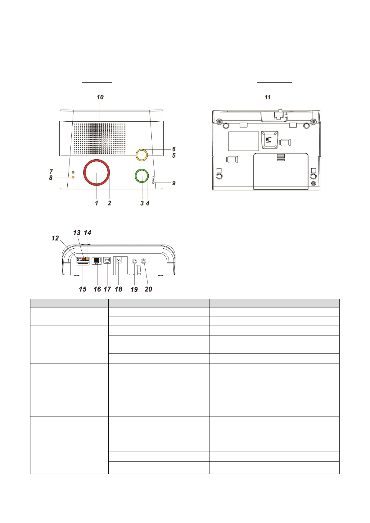
Button/LED/Component
Behavior
Function/Indication
1 Red Help Button
Press in idle mode
To summon emergency help
Press during incoming call
To answer the call
2 Red Backlight
Off
Idle mode
Flashes
1. During Guard time
2. During Help Arrived Mode
On
Alarm reporting
3 Green Reset Button
Press in idle/normal mode
1. To reset the inactivity timer
2. Dials Non-Emergency call
Press during Guard Time delay
To cancel the alarm reporting
Press during two-way mode
To terminate the two-way communication
Press and hold for 3 seconds in
idle/normal mode
To play voice prompt “GSM Signal (1-5)” to
announce the GSM signal strength for 1 min.
4 Green Backlight
On
1. Status reporting
2. During two-way communication for
non-emergency call, incoming call or call
back after alarm report.
Flashes
Panel in Callback mode
Off
Idle mode
2. System Overview
2.1. Parts Identification
Top View Back View
Side View
2
Page 6

5 Yellow Button
Press and hold for 3 seconds
To enter/exit learning mode
5 Yellow Button
When “Inactivity
Monitoring” is enabled
Press once
To toggle on/off the inactivity timer
6 Orange Backlight
On
The inactivity timer is on.
Off
The inactivity timer is off.
Blinking
The Control Panel is under learning mode.
7 Green LED (Volume
Switch)
On
AC power is on.
Flashes once every 2 seconds
AC power fails.
Press once
To increase the speaker volume
8 Orange LED (Volume
Switch)
Press once
To lower the speaker volume
Flashes every 3 seconds
The Control Panel is low on battery or is
having an overvoltage condition.
Flashes every 2 seconds
System has fault or jamming has been
detected
Flashes Every second
Telephone line fault
Off
System normal
9 Microphone
10 Speaker
11 Battery Switch
12 Reset Button
Reserved
13 Cellular Network Status
Indicator (red)
Flashes every second
Cellular network connection successful
Flashes every four
seconds.
Cellular network connection lost
14 Cellular Network Fault
Indicator (orange)
Reserved
15 SIM Card Base
Insert your SIM card in this slot.
16 Ethernet Port
17 USB Port
Reserved for factory use
18 DC Jack
Connects to a DC 12V 1.5A switching power adapter.
19 External Antenna
Terminal
Receiver (RX) only for LTE, please refer to 3.1 Hardware Installation & 6.1
GSM for installation and configuration method. (for GX-EX models only)
20 Main External Antenna
Terminal
Transmitter (TX) and Receiver (RX) for LTE, please refer to 3.1 Hardware
Installation & 6.1 GSM for installation and configuration method. (for GX-EX
models only)
3
Page 7

2.2. Power Supply
Plug the AC power adapter into the Control Panel’s DC jack and connect to the mains power.
Make sure that you use an adapter with the appropriate AC voltage rating to prevent
component damage. An AC-DC 12V/1.5A switching power adapter is generally used to power
the standard version of the Control Panel.
In addition to the AC power adapter, a rechargeable battery is installed inside the Control Panel
to serve as a backup in case of a power failure.
During normal operation, the AC power adapter is used to supply power to the Control Panel
and at the same time recharge the battery. It takes approximately 72 hours to fully charge the
battery.
If the battery switch is set as OFF, the battery will not be charged when AC power is connected
and nor will it serve as a backup power source when AC power is missing. You need to switch
the battery to ON for it to be charged when AC power is connected and serve as a backup
power source when AC power is missing.
AC Power Check Up
When AC power fails, Green LED will flash once every 2 seconds, and the panel will play voice
prompt “Power failure. Check power cord.” (if Voice Prompt is enabled)
When AC power failure time exceeds the selected AC Fail Report period, GX will send an AC
Failure report to the Monitoring Center.
When AC power resumes, the Green LED will turn steady on again, and the panel will play
voice prompt “Power restored.” (if Voice Prompt is enabled)
Low Battery
When the rechargeable battery is below the selected Low Battery detecting threshold, and the
low battery condition lasts for 30 minutes, GX will send a Low Battery report to the Monitoring
Center.
Battery Disconnection
GX detects the absence of battery in the following cases:
Battery switch OFF
Battery not connected
Battery failure
When the battery disconnection lasts for 30 minutes, GX will report to the Monitoring Center.
4
Page 8
<<NNOOTTEE>>
3. Installation Guide
3.1. Hardware Installation
Step 1. Choose a suitable location for the Control Panel. The Control Panel requires the mains
power and Ethernet connections and should be easily accessible. It should not be placed
in a damp location such as a bathroom or close to a heat source like a microwave oven,
which could reduce signal strength.
Step 2. Plug an Ethernet cable into the Control Panel’s Ethernet port and connect to an Ethernet
network.
Step 3. Plug the AC power adaptor into the Control Panel’s DC jack and connect to the mains
power. The Control Panel will power on and warm up a few seconds. After warm up is
complete, the Green LED will turn on to indicate the panel is now under normal operation.
SIM Card Insertion
The GX Control Panel features cellular network function to report to the Monitoring Station. The
SIM card base is located on the rear side of the unit. Insert the SIM card with the chip side facing
up. SIM Card will delete its SMS message whenever the GX Control Panel is powered on.
External Antenna installation
Please make sure to insert a SIM Card with data plan.
If the SIM Card is changed or removed, please power off the panel then power on again.
If a cellular signal fault occurs, please re-insert the SIM card and then reset the GSM in
GSM page.
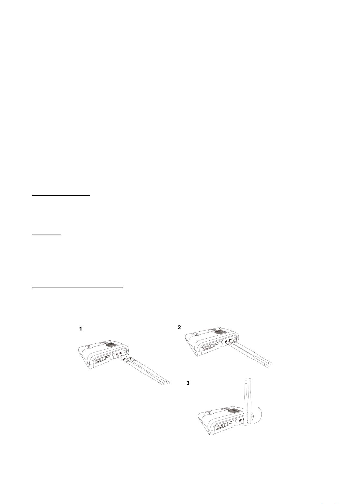
For GX-EX models, you may choose to install external antenna to improve signal strength.
1) Screw the LTE external antennas onto the antenna terminals of GX-EX.
2) Point the Tilt-Swivel antennas straight up as below.
3) On panel webpage, select Network Setting - GSM, and under GPRS, select "external" for
Antenna type (please refer to 6.1 GSM)
5
Page 9
3.2. Software Installation
3.2.1. Installing the Finder Software
The Control Panel could be accessed via Local Area Network for programming. The “Finder”
software is provided for user to locate the panel on the LAN for access.
Before you begin web programming, please make sure that you have plugged an IP cable into the
Control Panel’s Ethernet port and connected the cable to an Ethernet network for GX to operate via
Ethernet.
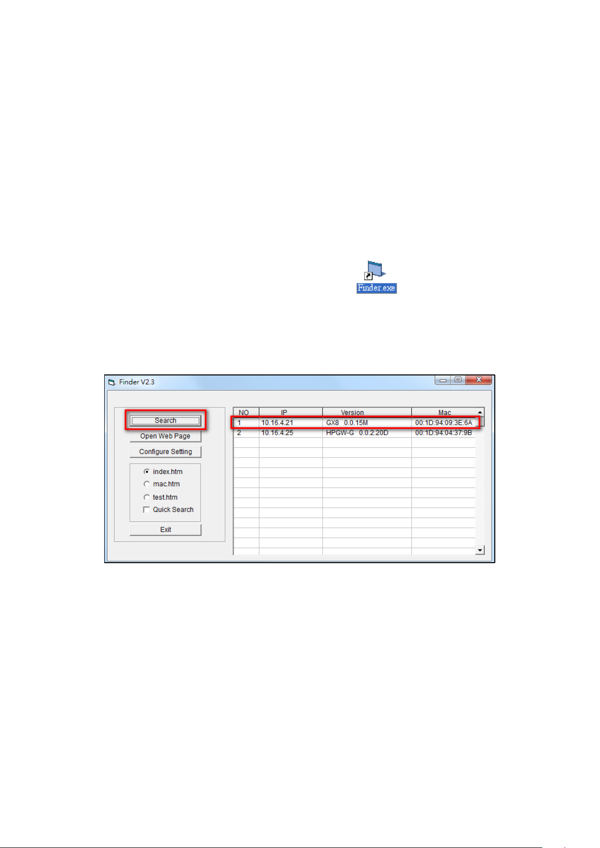
Step 1. Download the “Finder” software from Climax website, and execute the file to install Finder
software on your computer.
Step 2. A new icon will be displayed on your desktop.
Step 3. Click “Finder.exe” to execute Finder. The Finder software will search for your GX control
panel on the LAN and display its information including IP Address, Firmware Version and
MAC Address.
Step 4. If the GX Control Panel’s information is not displayed, check panel power and Ethernet
connection, then click “Search” for the software to update search result
If you need to program the panel’s network setting manually, click “Configure Setting”. Enter your
network setting, the GX username (default: admin) and password (default: admin1234) and click on
“OK” to confirm the settings. If the username and password are correct, a pop-up window will display
“Status: Configure success!!”
6
Page 10

3.2.2. Connecting to Local Programming Webpage
Step 1. Select the Control Panel in the Finder software and click on “Open Webpage” or simply
double click on the GX panel to connect to panel webpage.
Alternatively, enter the Control Panel IP address displayed in Finder into your browser’s
address section and proceed.
Step 2. You will enter panel Welcome page. The Welcome page displays current control panel
firmware version information according to different panel model and MAC address.
Step 3. Click on the pages and folders on the left to access the Control Panel’s various functions.
You will be prompted to enter the User name & Password before you can access the other
pages.
Default user name: admin
Default password: admin1234
7
Page 11

4. Device Management
UP to 100 RF devices may be learnt into the Control Panel.
4.1. Devices Learning
The devices may be learnt in locally using panel buttons, or through panel webpage operation.
The following types of accessory devices are supported:
RF device: All Climax RF devices are supported.
ZigBee device: models with built-in ZigBee module support All ZigBee devices with ZigBee
Home Automation 1.2 profile.
IP Cameras: The Control Panel is compatible with Climax VST-1818 Series IP Camera. Up to 6
IP Cameras are supported.
Z-Wave Device: Available for models with built-in Z-Wave module only, other models requires
additional USB Z-Wave Dongle.
Bluetooth Device: Available for models with built-in Bluetooth module only, other models
require additional USB Bluetooth Dongle.
4.1.1. Local Learning
Step 1. Under idle mode, press and hold the yellow button for 3 seconds. The panel will emit a
beep when button is pressed and the 2nd beep at 3 second. Release the button when the
2nd beep is heard. The panel will enter learning mode and the Yellow Button backlight LED
will begin to flash.
Step 3. Press the learn/test button on the device to transmit a learn/test code (please refer to the
device manual for more details)..
Step 4. If learning is successful, the Control Panel will emit 1 beep to indicate.
Step 5. After finish learning all devices, press and hold the Yellow Button for 3 seconds again to
exit Learning Mode.
Alternatively, the Control Panel will exit learning mode automatically after 5 minutes of
inactivity.
All learnt-in devices will be assigned to zone 1-100 sequentially.
8
Page 12

<<NNOOTTEE>>
<<NNOOTTEE>>
<<NNOOTTEE>>
4.1.2. Webpage Learning
Select Device Management – Learning/Inclusion from panel webpage.
Step 1. Click “Start” to enter learning mode.
Step 2. Press the learn button on the each device to transmit learn code.
For ZigBee sensors, press and hold the learn button for 10~12 sec to transmit a learn code.
For IP Camera VST-1818 Series, press and hold the Privacy button for 10 seconds.
For Bluetooth device, take a measurement with the device for it to search for Bluetooth signal.
Step 3. When the system received the signal transmitted from device, if the sensor you wish to learn
into already exists in the system, the sensor information will be displayed in the Learned
Device section. If not, the sensor information will be displayed in the Detected Device
section. The panel will also emit a beep.
It takes 5-10 sec for the Panel to receive a learn code from ZigBee or Z-Wave Sensor.
Step 4. Click “Add” to include selected device into panel.
For VST-862 F1 devices, press and hold the learn button for 3 seconds for the Control Panel
to receive a learn code, and then click “Add” within 30 seconds.
Step 5. If the device is successfully learnt into the system, the added device will be displayed in the
“Learned Device” section. After learning in all devices, click Stop to exit learn mode. The
system will automatically exit Learn mode if left idle for 5 minutes.
9
Page 13
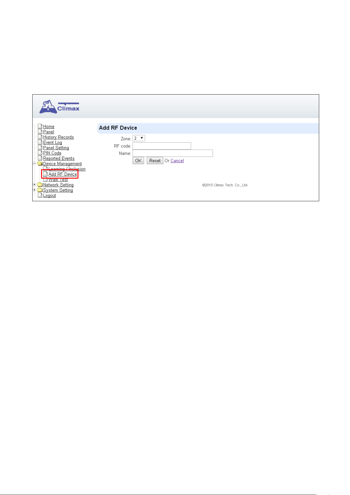
4.2 Add RF Devices
RF device may be added into panel without transmitting learn signal by enter the device’s RF code
via panel webpage.
Select Device Management – Add RF Device from panel webpage.
Step 1. Enter the device RF code and select a zone number.
Step 2. Enter device name (optional).
Step 3. Click OK to confirm. The device will be added to panel device list.
4.3 Walk Test (Range Test)
After complete learning all accessory devices, use the Walk Test function to test device signal range
before installing devices.
4.3.1 Walk Test
Step 1. Under idle mode, press and hold the yellow button for 3 seconds. The panel will emit a
beep when button is pressed and the 2nd beep at 3 second. Release the button when the
2nd beep is heard. The panel will enter learning mode and the Yellow Button backlight LED
will begin to flash.
Step 2. Move the device to a desirable location in the house and press the test button to observe
the device’s operational range.
Step 3. If the Control Panel responds with a beep, it means the device is within the operational
range.
Step 4. Press and hold the yellow button for 3 seconds again to exit learning mode. Alternatively,
the Control Panel will exit learning mode automatically after 5 minutes of inactivity.
10
Page 14
Step 1. Click “Start” to begin Walk Test.
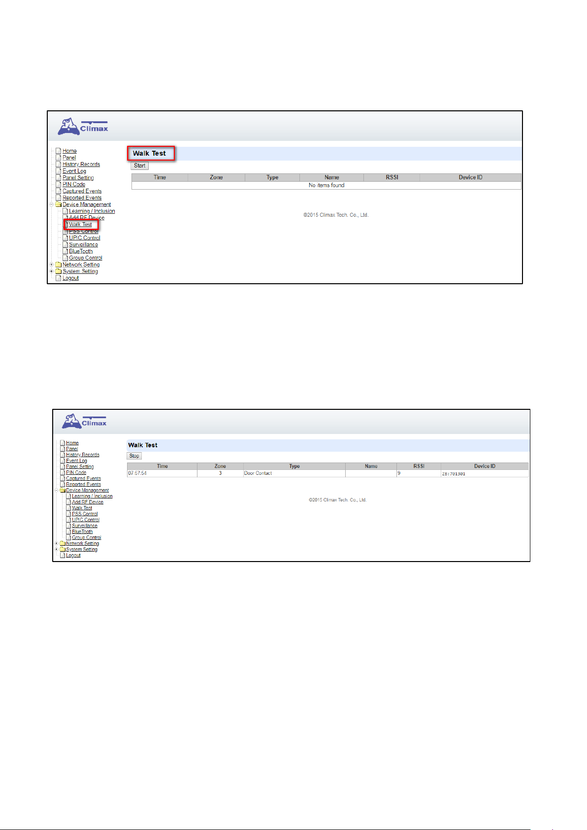
4.3.2 Webpage Walk Test
Select Device Management – Walk Test from panel webpage.
Step 2. Press the learn button on a learnt in device to transmit learn/test code.
Step 3. When the system received the signal transmitted from device, it will display device info on
the webpage. Device that has not been learnt into panel will not be displayed. Check the
RSSI value to determine if the signal strength is satisfactory.
11
Page 15
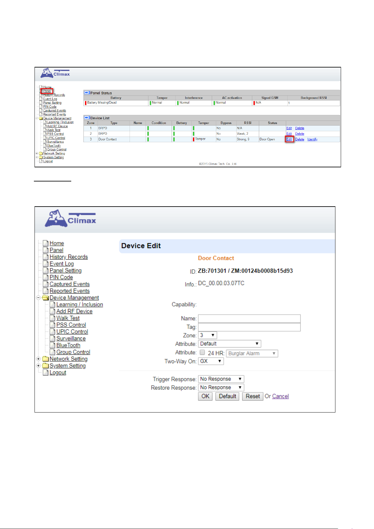
4.4. Edit / Delete /Identify Device
Select Panel from panel webpage to access panel device list.
Edit Device
Click “Edit” from the device entry under Device List to edit device info.
Enter or select the device information and click OK to confirm.
Name:
Enter the name for the device.
Tag:
12
Page 16

This is for you to label different types of sensors, such as power switch, power switch
meter, and hue. Devices with the same “tag” can be toggled on or off together. This
function is available in “Device Tag List” under PSS Control. See 4.5 PSS Control for
details.
Zone:
Select the Device zone number.
Attribute:
Please refer to 4.4.1 Edit Door Contact Special Attributes.
24 HR Attribute:
This function enables the device to activate selected alarm event whenever it is triggered.
Two-Way On:
Selec GX or 808RV for two-way communication.
Trigger Response
When the device is triggered, the Control Panel will activate selected Home Automation
Scene number. Please refer to 7.3. Scene webpage for detail.
Restore Response
When the device transmits restore signal after trigger, the Control Panel will activate
selected Home Automation Scene number.
Delete Device
Click “Delete” from the device entry under Device List to remove the device from panel.
Identify Device (For ZigBee device only)
The Identify function is available for ZigBee device only, it can be used to locate ZigBee devices after
learning.
For battery powered ZigBee devices, the identify fuction should be used within 1 minute after
pressing device button, or 3 minute after learning in the device. Otherwise due to ZigBee network
mechanisms, the device may not be able to receive signal successfullly from panel.
AC powered ZigBee devices do not have such limits and you can use Identify function anytime.
Step 1. Click “Identify” under the Device List after the device column entry.
Step 2. If the ZigBee device receives signal successfully, the webpage will display a success
13
Page 17
<<NNOOTTEE>>
message and the ZigBee device LED indicator will flash 10 times to confirm.
If a timeout message is displayed on webpage, it means the device did not receive signal
from Control Panel, please check ZigBee device range from panel and make sure to follow
instructions above about Identifying battery powered ZigBee devices.
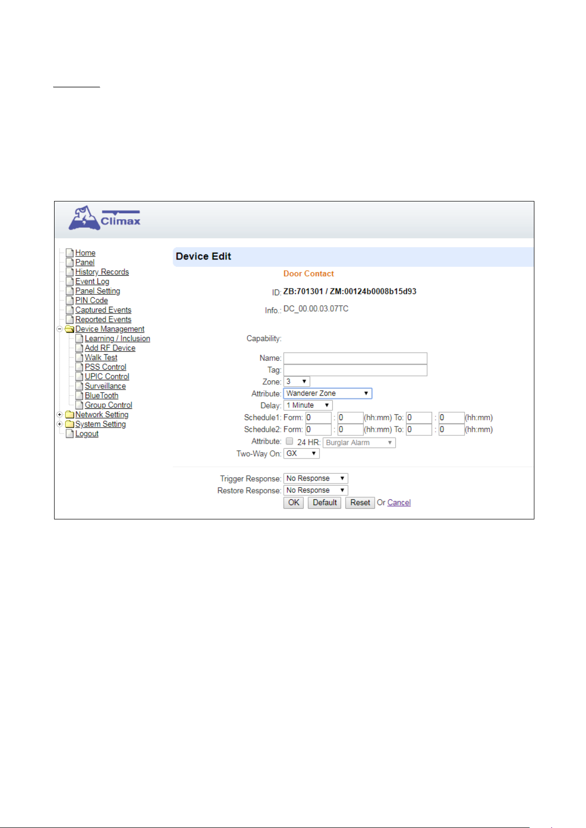
4.4.1 Edit Door Contact Special Attributes
Attributes:
Default: The Door Contact is used for Inactivity Monitoring function. Users can set the
schedules when the function will be enabled, and also the delay time period for trigger
(1-2-3-4-5-6-7-8-9-10-11-12-13-14-15-16-17-18-19-20-21-22-23-24-25-26-27-28-29-30
hours).
Wanderer Zone: When the system is armed by the home automation rule of “In Bed
Sleeping”, the Wanderer’s Zone type can be enabled for users to wander outdoor shortly
or let a pet go in/out of the door without triggering the Door Contact at the main entrance
door. The delay timer needs to be set (1-2-3-4-5-6-7-8-9-10-15-20-25-30 minutes), and
users are required to re-set/stop the entry timer and trigger one PIR detector when they
return back to the house/close the door. If users leave the house, and a PIR inside is not
14
Page 18

<<NNOOTTEE>>
triggered before the delay timer expires, a silent alarm will be triggered.
Not Back in Bed Zone: When the user shall be in bed sleeping, the Door Contact (wired
input) is connected to a bed detector (pressure detector) to monitor if the user stays in bed.
If the user needs to leave the bed shortly, e.g. for a WC visit, a delay parameter needs to
be set (1-2-3-4-5-6-7-8-9-10-11-12-13-14-15-16-17-18-19-20-21-22-23-24-25-26-27-28
-29-30 minutes). The user must return to bed within the delay time period, or a silent
alarm will be triggered.
Not Up From Bed Zone: The Door Contact (wired input) is connected to a bed detector
(pressure detector) to detect if the user doesn’t go up from bed at the scheduled time
period (e.g. Mon-Sun 08:00-10:00). The Door Contact will be triggered and send a silent
alarm if the Pressure Detector is not triggered within the scheduled time period.
Refrigerator Zone: The Door Contact is installed on the refrigerator to monitor that the
door is not kept open for too long or forgotten to be closed by the user. The delay timer
needs to be set (1-2-3-4-5-6-7-8-9-10-15-20-25-30 minutes). If the user leaves the
refrigerator door open for too long or forgets to close the door, a silent alarm will be
triggered when the delay timer expires.
Epilepsy Zone: The door contact (wired input) is connected to a special epilepsy detector
to detect an epilepsy event. The Door Contact will be triggered and send a silent alarm
when an epilepsy event is detected.
Delay Timer: Delay timer is set to delay an alarm signal to be transmitted within a period of
set time based on the above conditions.
Special attributes of Door Contact will be disabled if 24HR attribute is enabled.
15
Page 19
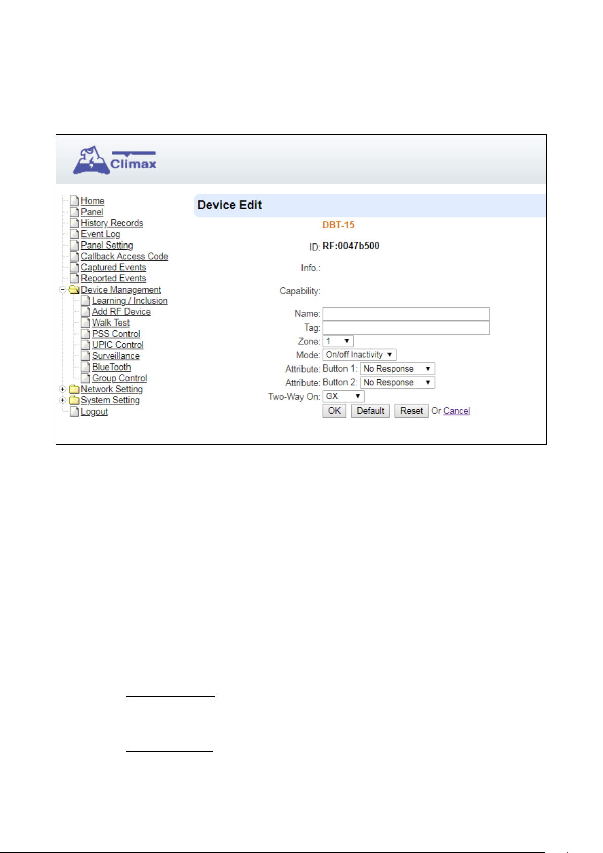
4.4.2 Select DBT-15 (Dual Button Transmitter) Operation Mode
The DBT-15 Dual Button Transmitter can operate as a panic button, ON/OFF inactivity switch, or a
Scene Selector according to different mode selected.
Mode:
On/Off Inactivity: When Inactivity Monitoring function is enabled (See 5.3 General
Setting), and DBT-15 is selected as ON/OFF inactivity switch, pressing the Green button
on DBT-15 will initiate Inactivity Monitoring, while pressing the Red button will stop
Inactivity Monitoring.
Panic Button: When DBT-15 is selected as Panic Button, pressing the Red button on
DBT-15 will activate the panic alarm. Pressing the Green button will send a cancel code to
the Control Panel to stop the alarm.
Scene Selector: When selected as Scene Selector, DBT-15 will operate as Scenario
Switch. Pressing the button(s) on the device will siganl to the Control Panel to activate the
correspondent scenario(s).
- Attribute Button 1: When the Red button is pressed, the Control Panel will activate
selected Home Automation Scene number. Please refer to 7.3. Scene webpage for
details.
- Attribute Button 2: When the Green button is pressed, the Control Panel will activate
selected Home Automation Scene number. Please refer to 7.3. Scene webpage for
16
Page 20
details.
Two-Way On:
Selec GX or 808RV for two-way communication when panic alarm is activated by DBT-15.
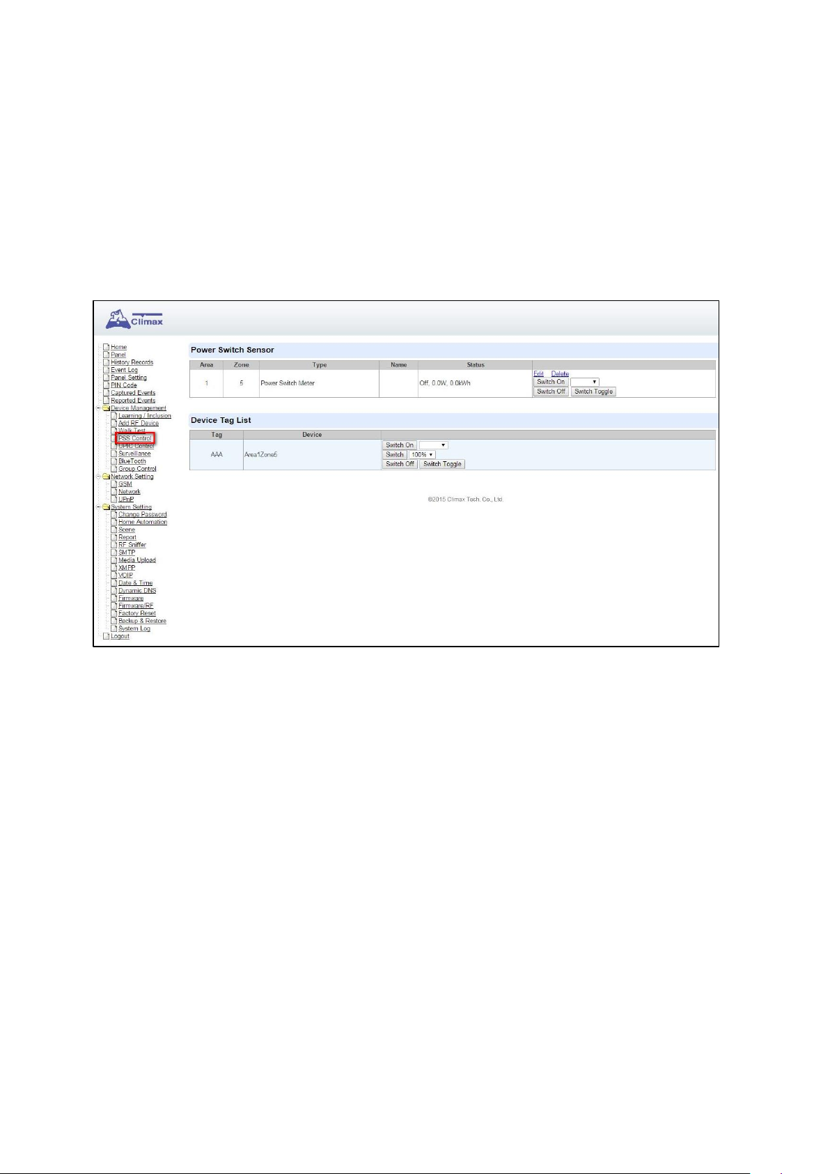
4.5. PSS Control
This feature is designed to control/edit/delete Power Switches included in the panel.
Click Edit to edit attributes of power switches.
Click Delete to remove power switch from panel.
Click Switch On/Switch Off to turn on/off power switches. Or click Switch Toggle to toggle
between on/off status. For Power Switch Dimmer, you can also set its power output level with
the slide down menu.
Labeled devices will be displayed under Device Tag List. This function is for you to open, close,
or stop your group of devices to a desired level.
17
Page 21
<<EEXXAAMMPPLLEE>>
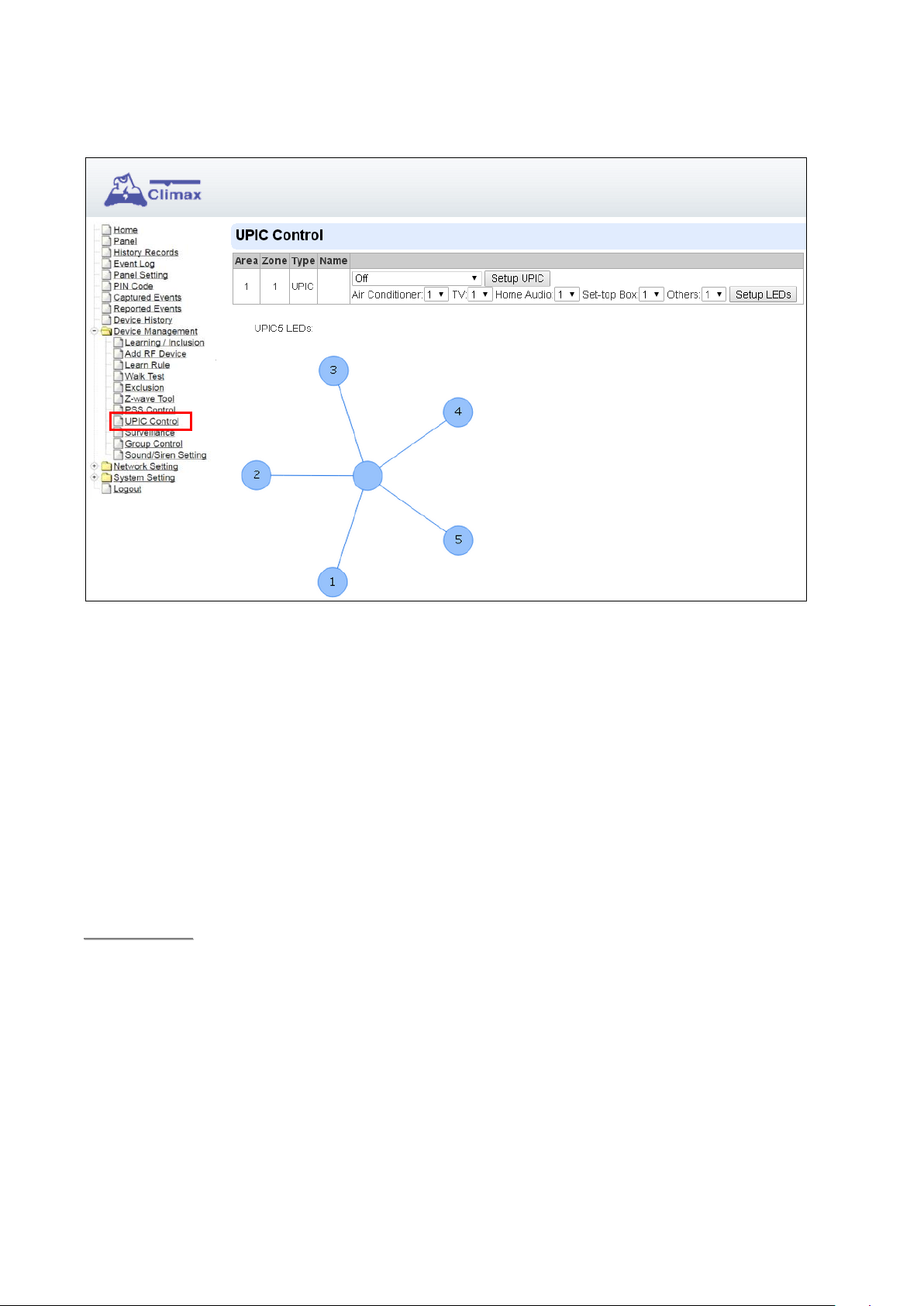
4.6. UPIC Control
UPIC Control webpage allows you to control UPIC IR Transmitter included in Control Panel
Transmit IR Signal
Depending on the UPIC model number, select the function to be performed in the drop down menu,
then click “Setup UPIC” for the UPIC to transmit IR Signal.
UPIC5 LED Setup (UPIC5 only)
UPIC5 has 6 IR LEDs, a central one and 5 surrounding ones. The central LED will always transmit IR
signal when activated; besides the central LED, one of the 5 surrounding LEDs can be selected to
activate upon IR signal transmission to increase the IR signal coverage.
Step 1: Refer to the diagram on the webpage and UPIC5 manual to determine which LED should be
used for signal transmission to each particular home appliance.
Step 2: Select the LED number from the drop down menu for each appliance type, then click “Setup
LED” to confirm. Please refer to UPIC5 manual for more information.
If “Air Conditioner” is set to LED 1, UPIC5 will transmit all Air Condition functions with both
If “TV” is set to LED 5, UPIC5 will transmit all Air Condition functions with both Central LED
Central LED and LED1.
and LED5.
18
Page 22
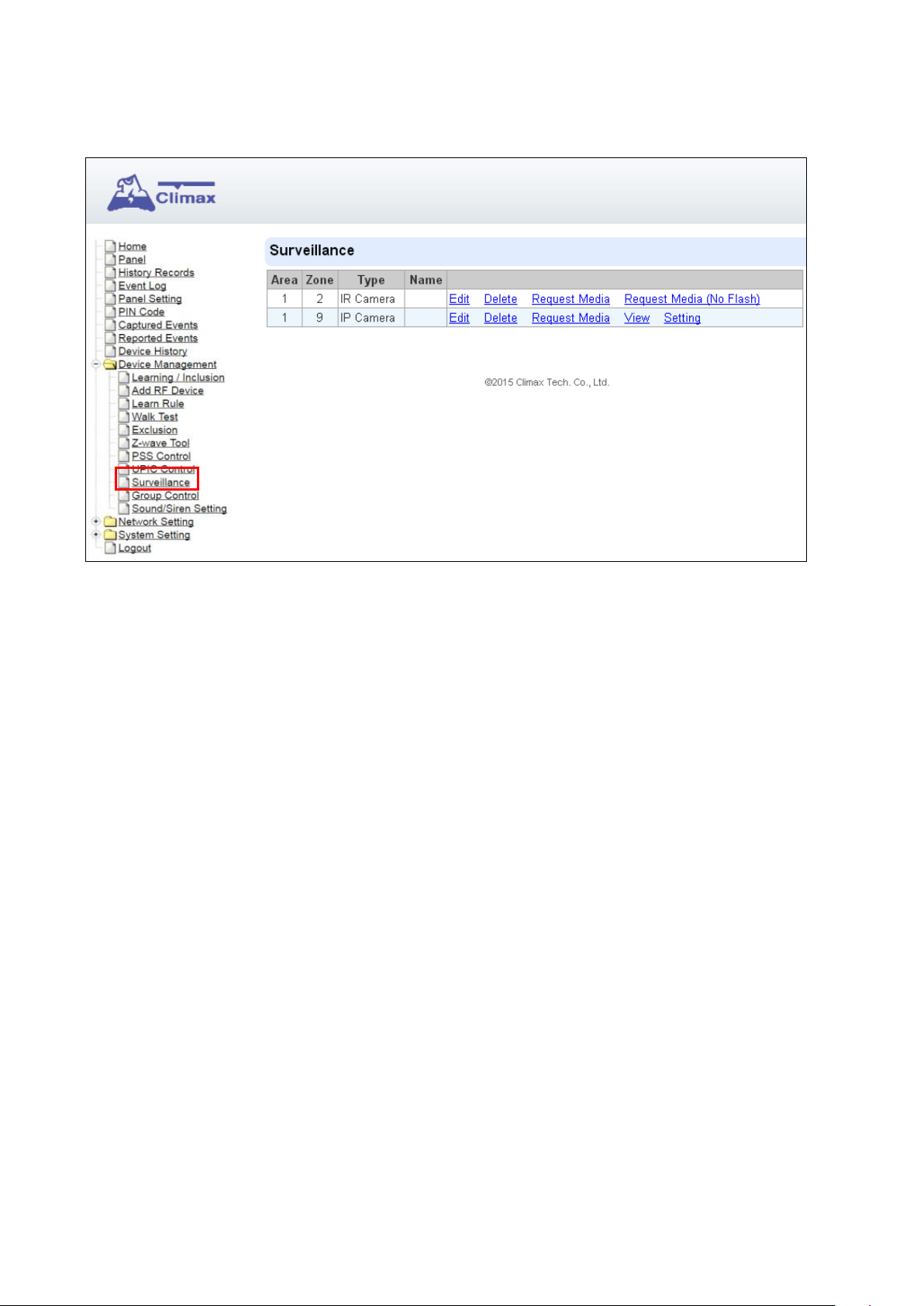
4.7. Surveillance
The PIR Camera/Video Cameras and IP Cameras are listed under Surveillance for separate control.
Click Edit to edit camera attributes.
Click Delete to remove device from panel.
Click Request Media to capture a picture or vide
PIR camera: A picture will be captured upon request
PIR Video Camera: A 10-second video will be recorded upon request
IP Camera: The IP Camera will record a video according to its video length setting (Please
refer to IP Camera manual for detail.)
For PIR Camera/Video Camera, you can choose to take the picture/video without
activating the camera’s flash.
Picture and video captured by PIR Camera and PIR Video Camera will be stored under the
Captured Event webpage. Video Recorded by IP Camera will be stored in the IP Camera,
please refer to IP Camera manual to view the video
For IP Camera, click “View” or “Setting” to access IP Camera webpage for video streaming or setting
configuration. A new webpage will open and you will be required to enter the username and
password for the IP Camera to access streaming or setting.
19
Page 23

4.8. Blue Tooth
Bluetooth transmission can be provided for GX models with built-in Bluetooth module. For GX
models without built-in Bluetooth module, an optional Bluetooth Dongle can be used to provide
Bluetooth transmission.
Once a Bluetooth device is learned into GX, the Control Panel can receive the device data via
Bluetooth transmissions.
Learning Bluetooth Device:
Step 1. Take a measurement with the Bluetooth device. The Bluetooth Indicator will flash fast,
indicating that the device is searching for Bluetooth signal.
Step 2. Put GX into learning mode by selecting Device Management – Learning/Inclusion from
panel webpage and click Start.
Step 3. The Bluetooth device information will be displayed in the Detected Device section. If no
device information is displayed, please leave learning mode, and then re-enter learning
mode.
Step 4. Click “Add” to include the Bluetooth device into the Control Panel.
Step 5. Once Bluetooth device is learned into GX, the Panel will automatically check the device
data every 5 seconds. If there is any update, data transmission will start, and the Bluetooth
device will automatically turn off when data transmission is completed.
20
Page 24

4.9 Group Control
This feature is designed for you to edit a name of group, switch on or off a group of Power Switches.
You can also assign Power Switches to groups you desire.
4.9.1 Group Control/Edit
Step 1. Specify a new name for a group.
Step 2. Click Switch On or Switch Off to turn on or off one group of power switches.
4.9.2 Device Edit/Delete
Step 1. Check on the groups you wish to assign the Power Switch. This is a multiple-choice field and
you can assign one Power Switch to multiple groups. Whenever one of the assigned groups
receives request to turn on/off, all Power Switches belonging to the group will be activated
accordingly.
Step 2. Click Edit to edit attributes of an added power switch or power switch meter or Delete to
delete this device.
21
Page 25

5 Panel Status / Setting
5.1 Panel Status
Click “Panel” to enter panel status page.
Panel Status:
The panel operation status is displayed. If any faulty condition is detected, the
corresponding status will turn red to indicate an error.
Device List:
The Device List display all learnt in devices for management. The device status are also
monitored and any faulty condition will be indicated.
22
Page 26

5.2 Panel Setting
Click “Panel Setting” to enter setting page.
AC Fail Report:
Set the waiting time before Control Panel report to Central Monitoring Station when AC
failure is detected.
AC Fail Suspend:
After AC failure is detected, the panel will enter sleeping mode and wake up at regular
interval. Use this option to set the wake up period duration.
Jamming Report
You can select to enable or disable jamming reports.
Auto Check-in Interval:
This is to select whether the Control Panel needs to send check-in reporting to the Central
Station automatically and to select the period of time between check-in reports.
Auto Check-in Offest Period
This is to set the time delay before the first Auto Check-In report is made. After power is
supplied or re-supplied to the Control Panel, the first auto check-in report will be made
according to Offset Period setting. This is used to test whether the CMS is able to receive
23
Page 27

the report from the Panel accurately.
After this test report is sent, the Control Panel will then send reports at regular interval
based on the setting of the Auto Check-in Report.
For example, if Offset Period is set to 2 Hours, and Auto Check-in Report is set to 12
hours, the Control Panel will make the first auto check-in report to the CMS after 2 hours,
and then make future auto check-in at a regular intervals of 12 hours.
Answering Incoming Calls:
When set as “Enable (Ring)”, the Control Panel rings for incoming calls. You can answer
an incoming call by pressing the Red help button on the Control Panel.
When this function is set as “Enable (Auto-Answer)”, the Control Panel will automatically
answer the call after the first ring and open full-duplex communication.
When this function is set as “Off,” the Control Panel does not answer incoming call at all.
Non-Emergency (Green):
Besides alarm reporting, the panel can be opened to make a non-emergency call without
activating an alarm.
Format: via sip server: sip:username or sip:username@server
via VOIP: sip:ip address
via GSM: voice://TelephonenNmber
Program the call recipient in this field. Press the Green Reset button when panel is idle to
make the Non-Emergency call.
LB detection:
Select the low battery detecting threshold.
Report Setting
Help Event Code:
You can select the event code to be sent to the CMS when the red button of the Control
Panel is pressed.
There are three options for the event code:
- Medical (100)
- Emergency (101)
- Panic (120)
2 Way Timer:
24
Page 28

To set the Two-way communication time duration.
Voice Prompt
On: The Control Panel will play voice prompts accordingly.
Off: The Control Panel will not play voice prompts.
Speech Report ACK:
Off-Hook: Speech report can be regarded as a successful report if the call recipient picks
up the phone.
Any DTMF: Speech report can only be regarded as a successful report if the call recipient
presses a DTMF button during the speech report. (For VOIP, GSM does not support
DTMF)
Speaker Volume:
Select a preferred speaker volume level for the Control Panel. (The higher the value, the
higher the volume level.)
Speaker Volume for 808RV:
Select a preferred speaker volume level for the 808RV.
Silent Panel & Device
Off: The Control Panel will sound beep and flash LED normally when it is activated by
button press or accessory devices. Two-way voice mode will be opened by default for
communication.
On: The Control Panel will NOT sound any beep when it is activated by button press or
accessory devices. One way listen-in voice mode will be opened by default for
communication.
Help Arrive Function:
Turn “On” to enable Help Arrived Mode.
Turn “Off” to disable Help Arrived Mode (System Default).
Reset with DTMF (0): (for VOIP, GSM does not support DTMF)
When enabled, Help Arrived Mode can be terminated by pressing the DTMF 0 key
(on the report recipient handset).
When disabled, pressing the DTMF 0 key is unable to terminate Help Arrived Mode
(For VOIP, GSM does not support DTMF).
25
Page 29

DTMF Command
During conversation for an emergency call, non-Emergency call, or callback call, the
following DTMF commands can be used to control the voice communication channel.
(This function is for VOIP only; GSM does not support DTMF detection.)
Enter (1) to decrease the speaker volume level.
Enter (3) to increase the speaker volume level.
Enter (4) to open two-way voice communication.
Enter (7) to listen in only.
Enter (8) to talk only.
Enter (0) to hang up.
Callback Timer:
After an alarm is successfully reported to the CMS, the Control Panel will start a waiting
period (=callback time) to auto answer any incoming calls from the CMS. The Green
Backlight will start to flash and a voice prompt “Please wait for the call back” will be played
to indicate it is in Callback Mode.
Available options include: Disable, 5 minutes, 10 minutes.
Check PIN Code (VOIP):
When Callback option is enabled, the CMS can call back during the call back timer to
communicate with the user(s). When CMS calls back to the panel, the panel will check for
CMS’s Access Code and # key entry.
When enabled, the panel will check Access Code.
When disabled, the panel will not check Access Code and will enter two-way
communication straight away.
Report Retrial:
Always: When selected, the Control Panel will continue retry reporting until successful.
Abandon: When selected, the Control Panel will only retry reporting for up to three times.
If reporting still fails after retrying for three times, the Panel will give up.
Network Priority:
Set the primary connection method to be used when Ethernet and GPRS coexist.
808RV Cancel:
When enabled, pressing the button on 808RV will end 2-way communication.
When disabled, pressing the button on 808RV will not end 2-way communication.
26
Page 30

5.3 General Setting
Scroll down the Panel Setting webpage to locate General Setting section.
Supervision Check
Select to enable or disable system supervision function. When ON is selected, the Control
Panel will monitor the accessory devices according to the supervision signal received.
Supervision Timer:
The Control Panel monitors accessory devices according to the supervision signal
transmitted regularly from the device. Use this option to set a time period for receiving
supervision signals. If the Control Panel fails to receive supervision signal from a device
within this duration, it will consider the device out of order and report the event
accordingly.
Supervision Timer (for DECT):
The Control Panel monitors DECT device according to the supervision signal transmitted
regularly from the device. Use this option to set a time period for receiving supervision
signals. If the Control Panel fails to receive supervision signal from a DECT device within
this duration, it will consider the DECT device out of order and report the event
accordingly.
Guard Time:
Non-Fall Sensor:
- Guard time normal is designed for any compatible sensor except for Fall Sensor (fall
detection).
27
Page 31

- The Control Panel will emit quick beeps during guard time.
- Alarm can be canceled during guard time.
- An emergency alarm cannot be cancelled after guard time has expired.
- If an emergency alarm is triggered by Fall Sensor, guard time will be determined by
- Triggering the following sensors will make instant reports and will not enter Guard
Fall Sensor:
- The Guard Time for Fall Sensor’s fall detection function is set separately from regular
- The Control Panel will emit quick beeps during Fall Sensor Guard Time.
- If a false alarm is triggered by Fall Sensor, it can be canceled within the guard time
the setting of Fall Sensor instead of the setting of guard time.
Time Delay:
Smoke Detector (SD), Water Sensor (WS), Carbon Monoxide Detector (CO), Heat
Detector (HD).
Guard Time.
period.
- This function is only used when a fall is detected, if the Fall Sensor button is pressed
to activate alarm, normal guard time is used instead.
Yellow Button Setting
Inactivity Monitoring:
Set to turn ON or OFF Inactivity monitoring function.
Inactivity Mode:
Interval: In this mode, pressing the Yellow Button to initiate or stop Inactivity Monitoring
countdown timer.
- Inactivity Time: Select the countdown time length for inactivity time. When this timer
expires without being reset, the Warning Period will start.
Schedule: The system will automatically initiate Inactivity Monitoring within the scheduled
times, and turn off when the schedule has expired.
- Schedule Setting: Set the start/end time of the schedule. Two schedules can be
programmed separately.
- Interval: Set the Inactivity Monitoring countdown timer during the scheduled time.
When this timer expires without being reset, the Warning Period will start according to
previous setting
Warning Period: During this period, the Control Panel will play a voice prompt “Inactivity
28
Page 32

timer expiring, please reset” once every 5 minutes. If Voice Prompt function is disabled,
the Control Panel will sound a beep instead. When the Warning Period expires, the
system will report an Inactivity Report to the CMS.
Start/End Action: This option determines if the Control Panel will report to CMS when the
Yellow Button is pressed (to toggle on/off of Inactivity Monitoring).
Sound Setting
Guard Time Beep:
Set to turn ON or OFF beep indication during guard time countdown.
Confirm Beep:
Set to turn ON or OFF beep indication during reporting process.
5.4 Callback Access Code
The Callback Access Code is used for incoming caller to establish two-way voice communication
with the panel during Call-back. When dialing to the panel during call-back, the dialer should enter
correct Callback Access Code for panel to pick up the call.
Enter the Callback Access Code setting in User Code, and click OK to confirm.
29
Page 33

6 Network Setting
6.1 GSM
Select Network Setting - GSM from panel webpage
GSM
Telephone
Enter the Telephone number of the SIM card, then press OK. (Please refer to 9.5. Alarm
session and Call Setup Methods. <crd>gsm:telephone number<crd> needs to be defined
in this filed.)
Check SIM
30
Page 34

<<NNOOTTEE>>
This is designed for the system to check the SIM card or not. (If users do not intend to use the
GSM funciton, please selsect “NO” to ensure the system will not check if the SIM card is
inserted or not and it will not display the GSM fault by LED flashing.)
GPRS
In order to allow GPRS to serve as a back-up IP Reporting method, this section will need to be
programmed before reporting.
APN (Access Point) Name
It is the name of an access point for GPRS. Please inquire your service provider for an APN.
When APN is set, the system becomes valid for internet connection.
User (GPRS)
It is the Log-in name to input before accessing the GPRS feature. Please inquire your
service provider.
Password (GPRS)
It is the User Password to input before accessing the GPRS feature. Please inquire your
service provider.
Antenna: (for GX-EX models only)
It is the antenna type (internal or external) to be selected for GX-EX models. For other
models, make sure to select internal antenna.
MMS
All values will be applied to both Areas 1 & 2.
The MMS settings are offered by your telecom service provider. Before configuring this function,
contact your service provider for correct MMS setting information of the inserted SIM card.
APN (Access Point) Name
Enter a MMS APN name provided by your service provider.
User
Enter the Log-in name for accessing the MMS feature provided by your telecom service
provider.
Password
Enter the password for accessing the MMS feature provided by your telecom service
provider.
URL
Enter the MMS APN URL provided by your telecom service provider.
Proxy Address
Enter the MMS Proxy Address provided by your telecom service provider.
Proxy Port
Enter the MMS Proxy Port provided by your telecom service provider.
SMS
SMS Keyword
For sending remote commands to system via SMS message, a personalized password is
required for the Control Panel to recognize your authority.
31
Page 35

SMS P-Word
Program Keyword is used to recognize the identity of a valid user; and to give authority for
Remote Installing (through SMS Text) or Remote Upgrading purposes (through GPRS).
This keyword will need to be inserted whenever the Remote Setting or Remote Upgrading
is required. A maximum of 15 characters is allowed.
Caller ID
The Caller ID function allows the Control Panel to instantly pick up an incoming call when
the incoming call number contains the number(s) programmed in this function..
For example, if a Caller ID is set as 70670, and there is an incoming call whose number is
044797067001, GX will regard it as matching the Caller ID and instantly pick up the call.
Up to 4 Caller IDs can be programmed.
Two-Way Setting
The two-way setting is designed to adjust microphone sensitivity for two-way communication.
There are 10 sensitivity levels for selection. Level 1 refers to lowest sensitivity level, while Level 10
refers to highest sensitivity level
Send SMS Message
This feature is designed for you to send a SMS message on this web configuration page.
Step 1. Click Send SMS.
Step 2. Enter a desired phone number and text message.
32
Page 36

6.2 Network
Select Network Setting – Network from panel webpage. This webpage is for you to program the
Network for IP connection.
Obtain an IP address automatically (DHCP)
If DHCP is selected, the Network will obtain an IP address automatically with a valid Network
DHCP Server. Therefore, manual settings are not required.
This is only to be chosen if your Network environment supports DHCP. It will automatically
generate all information.
Use the following IP address
You can also enter the Network information manually for IP Address, Subnet Mask, Default
Gateway, Default DNS 1 and Default DNS 2.
Please make sure that you have obtained all required values according to your Network
environment. Please contact your network administrator and/or internet service provider for
more information.
DNS Flush Period
You can set the system to clear current DNS resolution records for all entered URL settings
(Reporting, Upload, XMPP…etc.) after a set time period. The system will then resolve the
Domain Name again and acquire new IP address for the URL settings. This function is disabled
by default.
33
Page 37

6.3 UPnP
Select Network Setting – UPnP from panel webpage. UPnP is Universal Plug and Play, which
opens networking architecture that leverages TCP/IP and the Web technologies to enable seamless
proximity networking in addition to control and data transfer among networked devices in the home,
office, and public spaces.
Enable UPnP Device:
When enabled, you will be able to see this device via any UPnP discovery tool
Enable UPnP Port Redirect:
The device will try to find an UPnP-supported router and set up the port to redirect to the router.
Port Forwarding:
Port forwarding allows you to expose Web Server that you host on your LAN to external
Internet users.
1. Local Port - The port number seen by the Server on your LAN. Enter the port number
which the Server is configured to use.
2. External Port - The port number seen and used by Internet users. Enter the required port
number.
3. Protocol - Enter the required protocol (TCP or UDP).
34
Page 38

7 System Configuration
Select System Setting from panel webpage to access configuration webpages.
7.1 Change Password
This page is used to change the local webpage login user and password. Please note both User
Name and Password are case sensitive.
Step 1. Enter the preferred User Name in the “New Name” field.
Step 2. Enter the preferred Password in the “New Password” field and repeat the same Password in
the “Repeated Password” field.
35
Page 39

7.2 Home Automation
It is used to set Home Automation rules to control sensors and home appliances. You can set up to
100 rules.
Step 1. Click on Edit.
Step 2. Select an operation area.
Step 3. Set a rule condition.
Step 4. Set a rule schedule.
Step 5. Select the corresponding action rules in the Execution field.
Area
Select an operation area.
Rule Condition
The rule condition determines under which circumstances the rule should be activated.
Empty : When set as Empty, the system will follow the schedule time and execution rule to
respond accordingly.
Trigger Alarm : When set as Trigger Alarm, if the specified alarm event
(Burglar/Some/Medical/Water/Silent Panic/Panic/Emergency/Fire /CO Alarm) is triggered,
the rule will be activated according to rule schedule and execution setting.
36
Page 40

Temperature Below : When set as Temperature Below, if the temperature detected by
specified temperature sensor drops below set threshold, the rule will be activated according
to rule schedule and execution setting.
Temperature Above : When set as Temperature Above, if the temperature detected by
specified temperature sensor exceeds set threshold, the rule will be activated according to
rule schedule and execution setting.
Temperature Between : When set as Temperature Between, if the temperature detected
by specified temperature sensor falls within the specified range, the rule will be activated
according to rule schedule and execution setting.
High Power Consumption : When set as Power Consumption Above, if the power output
from a specific Power Switch exceeds the set threshold, the rule will be activated according
to rule schedule and execution setting.
Humidity Above : When set as Humidity Above,if the humidity reading from specified
room sensor rises above the level specified, the rule will be activated according to rule
schedule and execution setting.
Humidity Below : When set as Humidity Below,if the humidity reading from specified room
sensor falls below the level specified, the rule will be activated according to rule schedule
and execution setting.
LUX Between : When set as LUX Between, if the lux reading from specified light sensor
falls within the specified range, the rule will be activated according to rule schedule and
execution setting.
Rule Schedule
Always : When set as Always, the rule can be activated anytime.
Schedule Once : When set as Schedule Once, the system will follow the rule condition
37
Page 41

and execute rule according to the exact date and time specifed.
Schedule Every Month : When set as Schedule Every Month, the system will follow the
rule condition and execute rule according to date and time specified every month.
Schedule Every Week : When set as Schedule Every Week, the system will follow the rule
condition and execute rule according to day of the week and time specified every week.
Schedule Every Day : When set as Schedule Every Day, the system will follow the the
rule condition and execute rule according to time specified every day
Execution
Execution is the actual action performed by Control Panel when both Rule Condition and Rule
Schedule requirements are met
Zone Switch Off: Turn off the Power Switch at specified zone.
Zone Swich On : Turn on the Power Switch at specified zone.
Zone Swich On For : Turn on the Power Switch at specified zone for a set duration.
Zone Switch Level: Change the power output level for Dimmer at specified zone.
38
Page 42

Zone Swich Toggle : Toggle on/off the Power Switch at specified zone.
Group Switch Off : Turn off all Power Switches assigned to specified group.
Group Switch On : Turn on all Power Switches assigned to specified group.
Group Switch On For : Turn on all Power Switches assigned to specified group for a set
duration.
Request Image : The PIR Camera in specified zone will take a picture.
Request Image (All) : All PIR Cameras in the system will take a picture.
Request Image (No Flash): The PIR Camera in specified zone will take a picture without
activating its LED flash.
Request Image (All, No Flash) : All PIR Cameras in the system will take a picture without
activating LED Flash.
Request Video : The PIR Video Camera or IP Camera in specified zone will record a video.
Request Video (All) : All PIR Video Cameras and IP Cameras in the system will record a
video.
Setup UPIC: The UPIC and specified zone will transmit Off/Heat/Cool command to the air
39
Page 43

conditioner as programmed.
Trigger Alarm: Choose to activate one of the following alarms: High Temperature Alarm,
Low Temperature Alarm, High Power Consumption Alarm, High Humidity Alarm and Low
Humidity Alarm
Apply Scene: The system will execute preprogrammed Scene number. Please refer to 7.3.
Scene for detail.
40
Page 44

7.3 Scene
The Scene setting allows you to customize a series of actions with your devices, such as Power
Switch control, image/video request and trigger alarm. The programmed scene can be set to be
activated when a device is triggered. (See 4.4. Edit/Delete/Identify Device), or when a Home
Automation Rule is excecuted (See 7.2. Home Automation). For example, you can set a scene to
control multiple lightings, then set your Remote Controller to activate the scene when the button is
pressed, or set a Home Automation Rule to activate the scene.
Step 1. Click on Edit.
Step 2. Enter a name for the scene.
Step 3. Select an Area
Step 4. Select an action to be executed when the scene is activated. Refer to the Rule Execution
section in 7.2. Home Automation for detail.
41
Page 45

Step 5. Repeat Step 2-3 to setup the execution you want. As many as 5 executions can be
included in one scene.
Step 6. Click “Done”.
Step 7. Click “OK” at bottom of webpage to confirm the new scene setting..
7.4 Report
This report page programs report setting CID or VOIP reporting.
Reporting URL
This is used for installer to program report destinations.
1 Climax CID protocol via IP
Format: ip://(Account Number)@(server ip):(port)/CID
Example: ip://1234@54.183.182.247:8080/CID
2 SIA DC-09 protocol via IP
Format: ip://(Account Number)@(server ip):(port)/SIA
Example: ip://1234@54.183.182.247:8080/SIA
3 SIA DC-09 protocol via IP with AES encryption
Format: ip//(Account Number)@(server ip):(port)/SIA/KEY/(128,196 or 256 bits Key)
Example:
ip://1234@54.183.182.247:8080/SIA/KEY/4A46321737F890F654D632103F86B4F3
4 SIA DC-09 protocol using CID event code via IP
42
Page 46

Format: ip://(Account Number)@(server ip):(port)/CID_SIA
Example: ip://1234@54.183.182.247:8080/CID_SIA
5 SIA DC-09 protocol using CID event code via IP, with HEX encryption.
Format: ip//(Account Number)@(server ip):(port)/CID_SIA/KEY/(HEX)
Example:
ip://1234@54.183.182.247:8080/CID_SIA/KEY/4A46321737F890F654D632103F86B4F3
6 CSV protocol via IP
Format: ip//(Account Number)@(server ip):(port)/CSV
Example: ip://1234@54.183.182.247:8080/CSV
7 Voice via GSM
Format: voice://telephone number
Example: voice://0987654321
8 SMS via GSM
Format: sms://Account Number@telephone/CID or sms://telephone/TEXT
Example: sms://1234@0987654321/CID
9 VOIP
Format: report via sip server: sip:username or sip:username@server
report via lan: sip:ip address
Example: sip:john / sip:join@59.124.123.22
sip:192.196.0.10
10 Scaip Protocol Via IP
Format: scaip://Account@server:port
or scaip://Account:endpoint@server:port
or scaip://Account:endpoint@server:port/gsm:telephone
or scaips://ACCT:EndPoint@server:port/gsm:telephone (TLS encrypted)
Example: scaip://1234@59.124.230.221:53033
Level
Select a reporting condition:
All events: The system will report all events to this destination.
Alarm events: The system will only report alarm event to this destination.
Status events: The system will only report status event(non-alarm events) to this destination.
Group
Select a group for your report destination The system will make report according to the
following principle:
Group with higher priority will be reported first: Ex: Group 1 Group 2 Group 3….
If reporting to the first destination in a group fails, the system will move on to the next report
destination in the group.
If reporting to one of the report destinations in a group is successful, the system will
43
Page 47

consider reporting to this group successful and stop reporting to rest of the destinations in
the group. It will then move on to report to the next group.
If reporting to all destinations in a group fails, the system will retry report for 3 times. If
reporting is still unsuccessful after retries, the system will move on to report the the next
group.
After completing a round of reporting (From Group 1 Group 2 ….. Group5), If at one
group is reported successfully, the panel will stop reporting. If all report group fails, the panel
will wait for 5 minutes and restart reporting from group one.
If “Report Retrial” is selected as “Always” (Please refer to 5.2 Panel Setting), the panel will
not stop reporting unless at least one group is reported successfully.
If “Report Retrial” is selected as “Abandon” (Please refer to 5.2 Panel Setting), the Control
Panel will only retry reporting for up to three times. If reporting still fails after retrying for
three times, the Panel will give up.
44
Page 48

7.5 SMTP
Program the mail server related settings. The email account you set here would be used to send
report for events or picture and video clip captured by PIR Camera and PIR Video Camera.
Step 1. Enter the following settings:
Server: Set the mail server (max. 60 digits/alphabets).
Port: Set the port number (max. 5 digits/alphabets).
User: Set the mail account name (max. 30 digits/alphabets).
Password: Set the password corresponding to the mail account name (max. 30
digits/alphabets).
From: Set the email address according to your mail sever and account name. If your mail
server supports other email address, you can enter the email address here. (max. 30
digits/alphabets).
Using TLS/SSL encrypted channels (Secure SMTP): If your mail server uses TLS or SSL
encryption method for secure transfer, please click the box to enable the setting.
Step 2. Click OK to confirm the setting.
45
Page 49

<<NNOOTTEE>>
7.6 Media Upload
The system can deliver captured images and video clips captured by PIR Cameras and PIR Video
Camera to cell phone, email or ftp.
FTP: ftp://user.password@server/path
HTTP: http://ip:port/path
Email: mailto:user@server (transmitting an alarm image over Ethernet)
MMS via Telephone: mms: telephone number
MMS via GPRS: mms: user@mail.server (transmitting an alarm image over MMS)
If “Deleted events after uploaded” is checked, the system will automatically clear all
captured images which are displayed in the Captured Events menu after it successfully
sends out those captured images to preset reporting destinations.
46
Page 50

7.7 XMPP
This page is used to program XMPP server settings.
Server: Set server address.
Backup Server: Set backup server address.
Port: Set port number.
User: Set username.
Password: Set password.
Domain: Set domain address.
Buddy List: Set contact destination.
Ping Interval: Set the time interval for sending packets to server to check connection.
47
Page 51

7.8 VOIP
This page is use to program VOIP server setting.
To set the panel to connect to a VOIP sever, make to check both Enable VOIP Register and Enable
STUN, then enter the VOIP server info and click OK to confirm.
Unchecking both Enable VOIP Register and Enable STUN will disconnect the panel from VOIP
server. When disconnected, the panel can only make VOIP call via Local Area Network.
48
Page 52

7.9 Date and Time
For panel time setting.
Date & Time: Set current month, date and time.
Time Zone: Choose your time zone, and then the system will calculate the daylight saving time
automatically (if necessary).
Internet Time: The system will automatically synchronize with an internet time server. Tick the
check box to enable this function. Available options: pool.ntp.gov, time.nist.gov and
tick.usno.navy.mil.
49
Page 53

7.10 Dynamic DNS
This page is used to provide you the Control Panel’s current public IP address.
Dynamic DNS Server: default http://checkip.dyndns.org
50
Page 54

7.11 Firmware Update
This page is used to update main control panel firmware.
Step 1. Click “Browse/Choose File” and locate the latest firmware file (“unzipped image.bin” file)
in your PC.
Step 2. Click “Apply” to upload the latest firmware to Control Panel
Step 3. DO NOT power off during firmware update.
Step 4. Once Firmware update is complete, the Control Panel will reboot automatically.
51
Page 55

7.12 RF Firmware Update
This page is used to update RF firmware.
Step 1. Click “Browse/Choose File” and locate the latest RF firmware file (“unzipped image.bin”
file) in your PC.
Step 2. Click “Apply” to upload the latest RF firmware to Control Panel
Step 3. DO NOT power off during firmware update.
Step 4. Once RF Firmware update is complete, the Control Panel will reboot automatically.
52
Page 56

7.13 Factory Rest
Yan can clear all programmed parameters in the Control Panel and reset it to Factory Default.
Once the Factory Reset is executed, all the programmed settings will returned to its default value,
and all the learnt-in devices will be removed. You will need to restart the programming and learning
process again.
Step 1. Tick the Kept current network setting box to keep the current Network settings.
Otherwise, the system will reset its value back to factory default.
Tick the Kept current device list box to keep the current learnt-in devices. Otherwise, the
system will reset its value back to factory default.
Step 2. Click “Yes”.
Step 3. DO NOT power off during factory reset process.
Step 4. Once factory reset is complete, the Control Panel will reboot automatically.
Manual Factory Reset
The Control Panel will clear all programmed parameters when the following steps are taken.
Step 1. Unplug the power cord from the DC jack.
Step 2. Use a pen or screwdriver to slide the battery switch to the off position.
Step 3. Plug the power cord into the DC jack while pressing both the help and the reset
53
Page 57

<<NNOOTTEE>>
buttons until one long beep is emitted to indicate the factory reset has been
successfully executed.
Step 4. Release both buttons.
Step 5. Slide the battery switch back to the on position.
Step 6. Press Help and Reset buttons at the same time to power on.
Step 7. All 5 LEDs will flash 3 times to indicate successfully powering on. Continue holding
Help and Reset buttons for another 6 seconds. All 5 LEDs will then flash 3 times,
then release the buttons.
Step 8. Factory reset completed.
To verify whether you successfully reset the device, you will have to log in the Control
Panel.
7.14 Backup and Restore
Use this page to back up panel setting parameter and learnt in device info, and restore panel to
previous setting.
Backup Configuration File
Click “Download” to save panel setting file into your computer.
54
Page 58

Restore Panel Setting
Step 1. Click “Browse/Choose File” and select the previously downloaded configuration file from
your computer.
Step 2. Click “Apply” to upload the setting to panel.
7.15 System Log
The system log webpage logs the control panel’s detail system operation history.
Limit # of items: Click to select how many event are dislayed on the webpage
System Log File Download: Click to download a detailed log file into your computer for more
information.
55
Page 59

8 Event
This section introduces event history of the system.
8.1 Captured Events
This page stores all captured pictures and videos by PIR Camera and PIR Video Camera. You can
request the PIR Camera to take a picture and PIR Video Camera to take a 10-second video clip
manually.
Caputred events will be displayed in this page with their information for you to view. Simply click on
the picture or video to view them. You can also click Delete to delete the event.
Reload : Click to refresh the page content
Limit # of Items: Click the drop down menu on the page to select the number of captured events you
want to display.
8.2 Reported Events
This page stores all triggered events by the control panel by recording the events’ CID event code
and report status.
56
Page 60

Reload : Click to refresh the page content
Limit # of Items: Click the drop down menu on the page to select the number of reported events you
want to display.
8.3 Event Log
The Event Log page records specific actions performed by the Control Panel and accessory devices.
Reload : Click to refresh the page content
Limit # of Items: Click the drop down menu on the page to select the number of actions you
want to display.
57
Page 61

<<NNOOTTEE>>
9 Appendix
9.1 Help Arrive Mode
The Help Arrive function allows the CMS to monitor the progress of an alarm event and response of
help personnel after an alarm reported. To use this function, you should first enable Help Arrive
function in Control Panel setting.
The Help Arrive function operates according to following steps:
1: Entering Help Arrive Modes
After an alarm is triggered and reporting is complete, the panel will enter Help Arrive Mode and begin
a 15-minute Help Arrive Timer countdown. The Red Backlight will flash during this time. If the Help
Arrival Mode is not terminated by help personnel/nurse within 15 minutes, the Control Panel will
report the alarm event again and restart counting down the 15-minute time. The panel will countdown
the 15-minute timer and reset alarm report for up to 4 times (for a total of 60 minutes) before stop
retrying and return to idle mode.
If the option “Callback Timer” is enabled, call back option is always available during Help Arrive
Mode (and the Green Backlight will flash for the duration).
If the option “Reset with DTMF (0)” is enabled, pressing DTMF 0 on the caller handset during a
communication established in Help Arrive Mode will also terminate Help Arrive Mode. (For VOIP,
GSM does not support DTMF)
2: Help Arrival
Upon arrival, the nurse can determine the response according to different situation:
2-1 Patient needs help / Nurse begins treatment.
If the patient is in need of help/treatment, the nurse should press the Green Reset button once
to send a report that he has arrived at patient’s location and has begun to help the patient. The
Control Panel will play the voice prompt “Nurse Arrived”. The Help Arrive Timer will continue to
count down.
2-2 Patient has no danger.
If the nurse determines that the patient has no danger and does not need treatment or help, he
should press the Green Reset button twice quickly to send a report that patient does not need
help and the case is closed. The Control Panel will stop counting down the Help Arrive Timer
and return to idle mode.
58
Page 62

No
Voice Prompt
Condition
1
Emergency call was pressed.
Played once after pressing the Red Help Button on the Control
Panel, Active Button on Panic Button, WTR, Fall Sensor or
DECT device.
2
Help call in progress
Played once every 2-3 seconds during guard time
3
Help call cancelled
Played twice when the green reset button is pressed during
guard time
4
Alarm received. Please stand by.
Played once upon successful report
5
Line problem. Check line
connection.
Played twice when there is a line problem
6
Line connection restored
Played once when the Ethernet connection is restored
7
Power failure. Check power cord.
Played twice when a power failure takes place
3: Patient Treatment
After the nurse begins treatment (pressing Green Reset button once), depending on patient condition,
he may choose to end the case or call further help
3-1 Nurse needs help
If the nurse determines that the patient needs more help, he can press the Red Help button
again to send report that more help is needed. The Help Arrive Timer will continue to count
down.
3-2 Patient has no danger.
If the nurse determines that the patient has no danger and does not need treatment or help, he
should press the Green Reset button twice quickly to send a report that patient does not need
help and the case is closed. The Control Panel will stop counting down the Help Arrive Timer
and return to idle mode.
3-3 Treatment complete
When the nurse finishes treatment on the patient, he can press the Green Reset button one
more time to send report that his work is complete and the case is closed. The Control Panel will
play the voice prompt “Nurse Job Complete”, stop counting down the Help Arrive Timer and
return to idle mode.
9.2 Voice Prompt
The Control Panel plays voice prompts on important occasions to report its condition or
remind you to take a specific action. Information on voice prompts is provided in the chart
below.
59
Page 63

8
Power restored
Played once when power is restored.
9
Inactivity timer expiring. Please
reset.
Played once every 5 minutes during Warning Period. After
Warning Period, the Control Panel will start reporting.
10
A fall has been detected.
Played once when a fall sensor is triggered.
11
Fall detection has restored.
Cancelling help call.
Played after the reception of a fall sensor’s cancel code.
12
Please wait for the call back.
Played when the system enters the Call-Back mode.
13
Nurse arrived
Nurse arrived.
14
Nurse job completed
Nurse job completed.
15
You have forgotten to take your pill
Played once when the dosage is not dispensed by Pill
Dispenser after the schedule-dosage event.
16
GSM signal (1 - 5)
Played for 1 minute when the Green Reset Button is pressed
and held for 3 seconds in idle/normal mode to announce GSM
signal strength.
17
Please take you pill.
Played when it is time for medicine
9.3 SIA Digital Communication Standard
Please refer to the document “SIA Digital Communication Standard – Internet Protocol Event
Reporting (ANSI/SIA DC-09-2012A)” published by the Security Industry Association for details. An
example of an event reported in the SIA/CID format is as follows:
<0A><61><A4>004D"ADM-CID"0033L0#9999[#9999|1100 00
000][X121E35.057831][Y25N03.900375][P2772]<0D>
Where:
“ADM-CID” means that the content of this message is in the CID format.
0033 for <seq>
L0 for <Lpref>
#9999[#9999|1100 00 000]
9999 = account number
1100 00 000 = CID data (QXYZGGCCC)
[X...] and [Y...] are location data.
[P...] stands for the margin of error of cell location.
9.4 CID Event Code
100 Control Panel Emergency
When the Red Help button is pressed (“Help Event” set as 100).
101 Personal Emergency
When Wrist Transmitter/Emergency Pendant (WTR)/Fall Sensor/Panic Button is
pressed.
60
Page 64

When the Red Help button is pressed (“Help Event” set as 101).
102 Fall Detection
When a fall is detected from the learnt-in Fall Sensor.
110 Fire Emergency
When a device set to Fire attribute is triggered.
111 Smoke Emergency
When Smoke Detector (SD) is triggered.
114 Heat Emergency
When Heat Detector (HD) is triggered.
120 Panic
When the Red Help button is pressed (“Help Event” set as 120).
122 Silent Panic
When a device set to Silent Panic is pressed.
130 – Burglar
Whenever a device set as Burglar Alarm is triggered.
133 Burglar (24H)
Whenever a device set as 24H Burglar Alarm is triggered.
136 Burglar Outdoor
Whenever a device set at Burglar Outdoor is triggered.
137 Panel Tamper/ Panel Tamper Restore
When the panel’s tamper protection is triggered.
When the panel’s tamper function is restored.
147 Supervisory Failure – Sensor
When the Control Panel is unable to receive a signal transmitted from a sensor for a
period preset by the supervision timer.
151 Gas Emergency
When gas alarm is triggered.
154 Water Emergency
When Water Sensor (WS) is triggered.
158 High Temperature Alarm
When high temperature alarm is triggered.
159 Low Temperature Alarm
When low temperature alarm is triggered.
162 Carbon Monoxide Emergency
When Carbon Monoxide Detector (CO) is triggered.
170 High Power Consumption
61
Page 65

When high power consumption alarm is triggered.
171 High Humidity Alarm
When high humidity alarm is triggered.
172 Low Humidity Alarm
When low humidity alarm is triggered.
301 Panel AC Failure
When the Control Panel’s AC power failure time exceeds set AC Fail Report period.
302 Panel Low Battery
When the Control Panel is low on battery.
311 Panel Battery Disconnected
When the Control Panel’s battery is not connected.
344 Jamming Detected
When the Control Panel detects a jamming condition.
380 Device AC Failure
When an AC power device loses AC power connection.
383 Device Tamper/ Device Tamper Restore
When any device’s tamper protection is triggered.
When the device’s tamper function is restored.
384 Device Low on Battery
When a device is low on battery.
465 Panic Alarm Reset
When panic alarm has been reset.
389 Calibration Failure
When calibration fails.
602 Auto Check-In Report
When the Control Panel makes an auto check-in report to the CMS.
616 Call Request
When a call request has been made.
641 Inactivity
When the Control panel makes an inactivity timer expired report.
661 Nurse or Help Has Arrived/Nurse’s Job Completed
After Help Arrive Mode has been activated:
The first press on the Green Reset button upon nurse arrival will send report that a
nurse or help has arrived (1-661 with event qualifier “1”).
The second press on the Green Reset button after sending previous report (1-661)
will send report that the nurse’s job has been completed (3-661 with event qualifier
“3”).
62
Page 66

662 Help Still Needed
After Help Arrive Mode has been activated and help has arrived (1-661 reported)
When the Red Help Button is pressed to signal that help is still needed.
663 Case Closed by the Nurse
After Help Arrive Mode has been activated:
When the Green Reset button is pressed twice quickly to signal that the nurse
closes the emergency case because the user has no danger.
When DTMF 0 is pressed during Callback in Help Arrived Mode while the option is
enabled. (For VOIP, GSM does not support DTMF)
665 Inactivity check in/out
When Inactivity monitoring function is turned on/off/.
705 Medication Taken
After the dosage has been dispensed, a medication taken signal will be sent to the
Control Panel.
706 Medication Not Taken
If the dose is still not taken 30 minutes after the schedule-dosage event, a dose-not
–taken signal will be sent to the Control Panel.
707 Dispenser's Tray Stuck
When Pill Dispenser ‘s tray is stuck.
708 Dispenser upside down
When Pill Dispenser is upside down.
731 for Refrigerator Zone
Door Contact is triggered when the refrigerator is left open for too long.
732 for Wanderer Zone
Door Contact is triggered when PIR is not triggered.
733 for Not Back in Bed Zone
When Door Contact is triggered if Pressure Detecotr is not restored
734 for Not Up from Bed Zone
When Door Contact is triggered if the Pressure Detector is not triggered within the
scheduled time period.
735 for Epilepsy Zone
When Door Contact is triggered when an epilepsy event is detected.
759 Motion detection by CGMS
When Caregiver Motion Sensor detects motion.
63
Page 67

Action(1)/Restore(3)
Event
code
Device-type
Status-code
Location code
Voice
1
100
2
10
-
Yes 1 101
3, 50
10
-
Yes 1 102
5 9 -
Yes
1/3
110
47
9/3009
-
Yes/No
1/3
111
23
9/93
-
Yes/No
1/3
114
25
9/3009
-
Yes/No
1
120
5
10
-
Yes
1
122
10,14,21,23,25,2
6,331
10
-
Yes
1
130
28 9 -
Yes 1 133
28 6 -
Yes 1 136
14 6 -
Yes
1/3
137
2
125/94
-
Yes/No
1/3
147
10,14,21,23,25,2
6,33
2
42/124
-
No
1/3
151
21
9/3009
-
Yes/No
1/3
154
33
9/93
-
Yes/No
1
158
19
100
-
Yes 1 159
19
101
-
Yes
1/3
162
26
9/93
-
Yes/N
1
170
3,5,10,14,21,23,
6 - Yes
1
2
CID/SCAIP Event Code Table
For Device Type 10(PIR/EIR), 14(DC/DC-15), 21(GAS), 23(SD), 25(HD), 26(CO), 33(WS), Status
Code is 10.
For Device Type 10(PIR/EIR), 14(DC/DC-15), 21(GAS), 23(SD), 25(HD), 26(CO), 33(WS), Status
Code is 42 or 124.
64
Page 68

25,26,33,50
1
171
3,5,10,14,21,23,
25,26,33,50
6 - Yes 1 172
3,5,10,14,21,23,
25,26,33,50
6 - Yes
1/3
301
2
85/86
-
No
1/3
302
2
16/15
-
No
1/3
311
2
14/15
-
No
1/3
344
2
95/94
-
No
1/3
380
50
105/3105
-
No
1/3
383
10, 143
125/3125
-
No
1/3
384
3,5,10,14,21,23,
25,26,33,504
16/15
-
No
1/3
389
21,23,25,26,
32/3000
-
No 1 465
21,23,25,26,33,
0 - No
1
602
2
102
-
No
1
616
2 0 -
No
1/3
641
2
119/93
-
No
1/3
661
2
88/3088
-
No
1
662
2 6 -
Yes 1 663
2
97
-
No
1/3
665
2
111/121
-
No
1
705
11
83
-
No 1 706
11
81
-
No
3
4
For Device Type 10(PIR/EIR) and 14(DC/DC-15), Status Code is 125 or 3125.
For Device Type 3(WTR/RC), 5(Fall), 10(PIR/EIR), 14(DC/DC-15), 21(GAS), 23(SD), 25(HD),
26(CO), 33(WS), 50(Other), Status Code is 16 or 15.
65
Page 69

1/3
707
11
67/94
-
No
1/3
708
11
105/3105
-
No 1 731
14
77
21
Yes
1
732
15
39 3 No
1/3
733
12
3/3003
21
No 1 734
12
07
12
No 1 735
17
07
12
Yes
1
759
101
6 - No
<<<<NNOOTTEE>>
All Device Type: please refer to the following information to identify the device type being
triggered:
2 for Local Unit & Controller
3 for WTR/RC
5 for Fall
10 for PIR/EIR
14 for DC/DC-15
21 for GAS
23 for SD
25 for HD
26 for CO
33 for WS
101 for CGMS
102 for TS
50 for other type of sensors
66
Page 70

<<NNOOTTEE>>
9.5 Alarm Session and Call Setup Methods for SCAIP Report
When SCAIP report is successful, two-way communication can be set up with the following two
methods:
1) Normal Outgoing Call
After receiving SCAIP report, server will set up an outgoing call to a pre-defined receiver according to
the callhandling reply setting of server response.
If the callhandling-reply item (cre) is set as <cre> 61</cre>:
Server will automatically set up a voice call to the GSM telephone number defined in the
SCAIP reporting url.
<Reporting URL example>:
164565:scaipclimax@59.124.230.221:5060/gsm:886922123456
If the callhandling-reply item (cre) is set as <cre>62</cre>:
Server will automatically set up a voice call to the transferred number defined in the
transferred-number item (tnu), for example <tnu>gsm:+46701445566</tnu>.
<Reporting URL example>:
164565:scaipclimax62@59.124.230.221:5060
2) Callback Request
After receiving SCAIP report, server will call back to the alarm sender according to the callhandling
reply setting of server response. When the callhandling-reply item (cre) is set as <cre>nn</cre>,
nn=01~60:
Server will call back in nn minutes. The alarm receiver needs to have registered the valid
sender Telephone number or the number or identity contained in the <crd>gsm: telephone
number</crd> or <crd>sip:ip address</crd>.
<Reporting URL example>:
164565:scaipclimaxcb@59.124.230.221:5060
<crd>gsm:telephone number</crd> needs to be defined in the Telephone field in
Network Setting – GSM webpage (Page 30).
For <crd>sip:ip address</crd>, users need to enter VOIP SIP settings in System
Setting - VOIP webpage (Page 48), and get registered at VOIP Server.
67
Page 71

<<NNOOTTEE>>
SUPPR:PROG,1111,720
SUPPR
=
Programming command
:
=
Colon
PROG
=
SMS Keyword
,
=
Comma
1111
=
Access Code
,
=
Comma
720
=
Programmed parameter
<<NNOOTTEE>>
9.6 SMS Programming
You can do SMS remote programming via a mobile phone or SMS iWizard.
SMS Remote Programming via a Mobile Phone
Please change the language setting of your mobile phone to English before you
proceed with SMS remote programming.
Step 1. Enter the SMS screen on your mobile phone or smartphone.
Step 2. Enter the programming command (see the SMS remote programming commands
tables below).
Step 3. Enter a colon (:).
Step 4. Enter SMS Keyword (default is PROG).
Step 5. Enter a comma (,).
Step 6. Enter the Access Code (default is 1111).
Step 7. Enter a comma (,).
Step 8. Enter the parameter(s).
Step 9. The composition of the command is completed. You can send the command to the
GX system now.
Example: To set 720 minutes for the supervision timer, you can send the following
command:
You can compose multiple commands in one SMS text message by using “;” to
separate each command.
68
Page 72

Item
Command
Example & Usage
Default
GPRS APN,
username &
password
APN
APN:PROG,1111,internet,,
To set GPRS APN, username and password (31 characters max. for APN, 31
characters max. for username, 31 characters max. for password)
--
Report settings
RPT
RPT:PROG,1111,1,voice://0987654321,1,0
To configure report settings (index number, report destination, group, and event
filter). Refer to 7.4 Report for details.
Index number: 1-20
Report destination: Depends on the selected reporting format (type).
Group number: 1-5
Event filter: 0 = all event, 1 = alarm event, 3 = status event
In the example above, the report index number is 1 with the reporting destination
at voice://0987654321(Voice via GSM); report priority is Group1 with report
condition as all event.
--
Checking the
Control Panel
ECHO
ECHO:PROG,1111
To check whether the Control Panel can respond properly
--
Rebooting the
Control Panel
RESET
RESET:PROG,1111
To reboot the Control Panel
--
Keyword setting
KEYWD
KEYWD:PROG,1111,IPOG
To set the keyword
15 characters max. for the keyword
--
Access Code
ACCES
ACCES:PROG,1111,1234
Parameter 1: Access Code: maximum of 8 numeric digits
--
Auto check-in
reports
TESTC
TESTC:PROG,1111,720,60
To configure the settings of auto check-in reports (interval: __ minutes, offset time:
__ minutes)
Interval: 0 = disable, 60 = 1 hr, 120 = 2 hrs, 180 = 3 hrs, 240 = 4 hrs, 360 = 6 hrs,
480 = 8 hrs, 720 = 12 hrs, 1440 = 1 day, 2880 = 2 days, 4320 = 3 days, 5760 = 4
days, 7200 = 5 days, 8640 = 6 days, 10080 = 1 week, 20160 = 2 week, 30240 = 3
week, 40320 = 4 week
Offset time: 60 = 1 hr, 120 = 2 hrs, 180 = 3 hrs, 240 = 4 hrs, 360 = 6 hrs, 480= 8
hrs, 720 = 12 hrs
--
Supervision
SUPPR
SUPPR:PROG,1111,1,720
To set the supervision timer and supervision check
Parameter 1: supervision check 0 or 1
Parameter 2: supervision timer: 0 = disable, 240 = 4 hrs, 300 = 5 hrs, 360 = 6 hrs,
480 = 8 hrs, 720 = 12 hrs, 1440 = 24hrs
--
Factory reset
FTSET
FTSET:PROG,1111,0,1
To execute a factory reset
Parameter 1: Keep NET configurations (1 = keep; 0 = Not Keep)
Parameter 2: Keep all devices and their programmed attributes (1 = keep; 0 = Not
Keep)
--
Remote Firmware
Update
FWUG
FWUG:PROG,1111,N,0.0.15B,192.168.0.105:53038/GX8_oz-0.0.15B.bin,aa3480
a1e540999b7de78ab07aea3cd5
Parameter 1:Update module, N:Net, A:RF/51
Parameter 2:Firmware version
Parameter 3:Firmware download path
Parameter 4:Firmware MD5
--
Request
Firmware Version
FMG
FMG:PROG,1111
The panel will send back current firmware version info.
--
SMS Remote Programming Commands Table
69
Page 73

SMS Remote Programming via SMS iWizard
GX is compatible with Climax’s SMS iWizard, which is designed to facilitate SMS remote
programming via a PC. This tool allows you to conveniently program GX from your PC
without sending SMS text messages from a mobile phone.
70
 Loading...