

Clifford Prime Level TWO Installation Manual

The Science of Security™
Prime
Level
TWO
SECURITY
UPGRADE
PACKAGE
E
N
G
E
R
H
T
R
U
O
F
M
O
B
I
A
T
I
O
N
Installation Manual
Y
T
I
R
L
U
E
C
S
E

Table of Contents
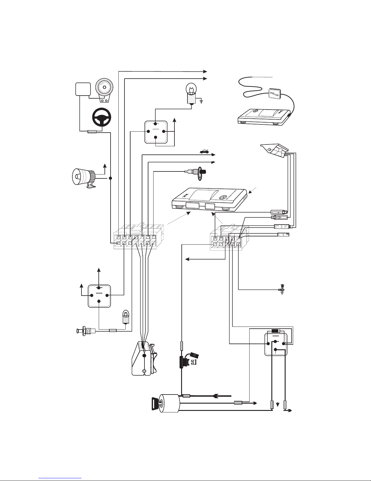
Wiring Diagram ...................................2
Important Information ................................3
Required Installation Tools .............................3
Modes: Dealer Mode, Sleep Mode, Customer Mode ................3
Passenger Compartment Components ........................3
Control Unit and Receiver..................................3
Ignition & Starter ......................................3
LED & Valet Switch Assembly ................................3
Door Trigger ........................................4
Optional Interior Light Illumination..............................4
Door Locks ........................................4-5
Single-Stage ......................................4
2-Stage .........................................5
Parking Lights........................................5
Horn Connection ......................................5
Optional Dual-Zone Piezo Vibration/Impact Sensor .....................6
Optional Trunk Trigger Connection .............................6
Auxiliary A Output .....................................6
Optional Engine Compartment Components ....................6
Optional Siren .......................................6
Final Wiring Connections ..............................6
MANDATORY MASTER REMOTE CONTROL ADDITION ................7
Delayed Courtesy Lights ...............................7
Remote Control Operation ..............................7
Eight-Event TotalRecall ...............................7
Programmable Features ...............................8
Programming the User-Selectable Features ........................8-9
Using CliffNet Wizard PRO .................................9
Installer Programmable Features .............................9-10
System Checklist & Troubleshooting ......................10-12
NOTE: The Prime Level 1-5 products are designed for easy, plug-in upgrade.
Thus the Level 1 harness is used in the Level 2 installation, the Level 1 and 2
harnesses are used in the Level 3 installation, and so on.
1
ac
Siren/Car Horn
Output
Factory
Car Horn
Relay
White/Green (door lock + or -)
White/Orange (door unlock + or -)
Parking Lights
See Door
Lock/Unlock
Section of
This Manual
Car Horn
OR
Optional
Siren
NegativeTrigger Pin Switches,
or +12Vfor PositiveTrigger
+12V
+12 Volts
Red
Black
Yellow (horn/siren -)
Connect toGround for
Pin Switches
Optional
Interior
Light Relay
87
87a
86
85
30
Interior
Door
Switch
Light
Piezo Sensor
87
86
Brown (Parking light output -)
14 13 9 8
76543 21
Brown/White
(interior light output-)
Gray (door trigger + or -)
Black
Red
Blue
Orange
Optional
Dual Zone
+12V
85
Optional Parking
Light Relay
87a
30
Gray/Violet (ch. A out -)
Gray/Blue
Gray/Yellow
(trunk input -)
(armed output 2 -)
(battery +)
Red
Trunk
Switch
10 6
Green/White
Accessory
Not Used
543 21
(armed output 1 -)
Green
Prime Level 2 Control Unit
Underdash LED/Valet
Switch Assembly
DataPort
Violet (LED +)
Black (ground -)
White (valet switch -)
Black (ground -)
Gray (data input)
Black (ground -)
Black
(ground -)
White/Brown
Violet
Black
k
Bl
White
Not
MX
2E
Used
Ground
87
87a
86
85
30
Ignition
Switch
5 amp
Fuse
Constant +12V Supply To Switch
2
White/Brown
(ignition input +12V)
Ignition
White/Red
White/Red
(starter disable)
Cut
X
(starter disable)
Starter
Important Information
1. Use a voltmeter. DO NOT USE A TEST LIGHT! Test lights have a current drain that
will damage the vehicle’s onboard computer or could trigger the air bag.
2. Keep extension, if needed, as short as possible. Use same-gauge wire for extensions.
3. DO NOT mount components nor route wires near hot or moving vehicle parts.
NOTE: Clifford Electronics’ web site for Authorized Clifford Dealers has
detailed descriptions of wire colors and locations for most foreign and
domestic vehicles. See www.clifforddealers.com for assistance 24-hours per
day or refer to the latest quarterly Tech Support Database CD-ROM.
Required Installation Tools
Voltmeter (set to DC Volt)
n
Wire crimper
n
Wire stripper
n
Electric drill and bits
n
Phillips screwdriver
n
Crescent wrench
n
Vinyl tubing
n
Rubber grommet (if firewall pass-through is needed)
n
Modes: Dealer Mode, Sleep Mode, Customer Mode
There are three modes to provide the utmost flexibility for expediters and new vehicle dealers:
Dealer Mode:
n
system respond only to the master remote in this mode. Beeps are muted, panic and car-finder
features are off, and AutoArm and AutoArm & Lock features are on. Programming the Customer
Care Kit remotes switches the system to Customer Mode and auto-deletes the master remote.
n
Sleep Mode:
the system inoperable in cases where it is not feasible to remove the system control unit. To ensure
against accidental customer access, Sleep Mode is accessible only if the system is in Dealer Mode.
n
Customer Mode:
This is the as-shipped operating mode after you program the master remote. The
This mode completely disables the system. It is intended for unsold pre-loads to make
This is the normal operating mode for the new car purchaser.
Passenger Compartment Components
Control Unit and Receiver
Never install the control unit under the hood.
1. Select a mounting area, but do not affix the control unit until wiring and testing is complete.
2. Plug in the receiver module. Do not fold or make sharp bends in the cable or antenna wire.
For maximum range, mount the receiver module away from the control unit and run the
antenna up the window pillar and affix it to the windshield about an inch from the roofline.
Ignition & Starter
1. Find the wire in the steering column or ignition switch wireloom that shows +12V throughout
BOTH the cranking AND engine running cycles, and 0 volts when the ignition is off.
2. Connect the WHITE/BROWN wire to the ignition line.
3. Find the wire that shows +12V during the cranking cycle ONLY.
4. Cut it and connect a WHITE/RED wire to each side of the cut wire.
LED & Valet Switch Assembly
1. Select an underdash area to mount the assembly where there is clearance for the screws
and will position the LED so it is visible through the windows.
2. Mate the assembly’s connector to the control unit connector of the same colors.
NOTE: The GRAY & BLACK wire 2-pin connector isnot used on the Level TWO.
3
 Loading...