


Notebook Computer
W330AU / W331AU
Service Manual
Preface
Preface
I
Introduction
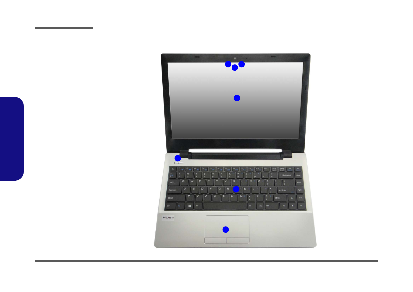
Figure 1
Top View
1. PC Camera
2. *PC Camera LED
*Whe
n the PC
came
ra is in use,
the LED will be
illuminated in red
3. Built-In Microphone
4. LCD
5. Power Button
6. Keyboard
7. Touchpad & Buttons
5
7
6
3
1
2
4
External Locator - Top View with LCD Panel Open
1.Introduction
1 - 4 External Locator - Top View with LCD Panel Open
External Locator - Front & Right Side Views
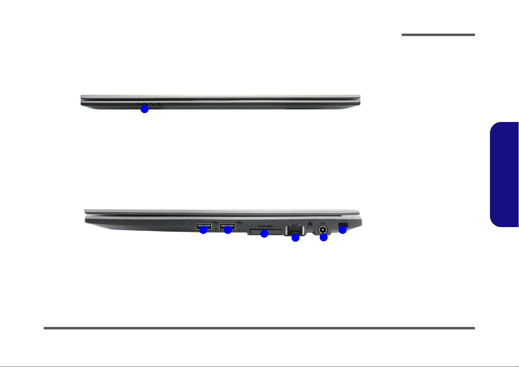
Figure 2
Front View
1. LED Indicators
Figure 3
Right Side View
1. USB 2.0 Ports
2. Multi-in-1 Card
Reader
3. RJ-45 LAN Jack
4. DC-In Jack
5.
Security Lock
Slot
1
FRONT VIEW
RIGHT SIDE VIEW
1
3
2
1
4
5
Introduction
1.Introduction
External Locator - Front & Right Side Views 1 - 5
1.Introduction
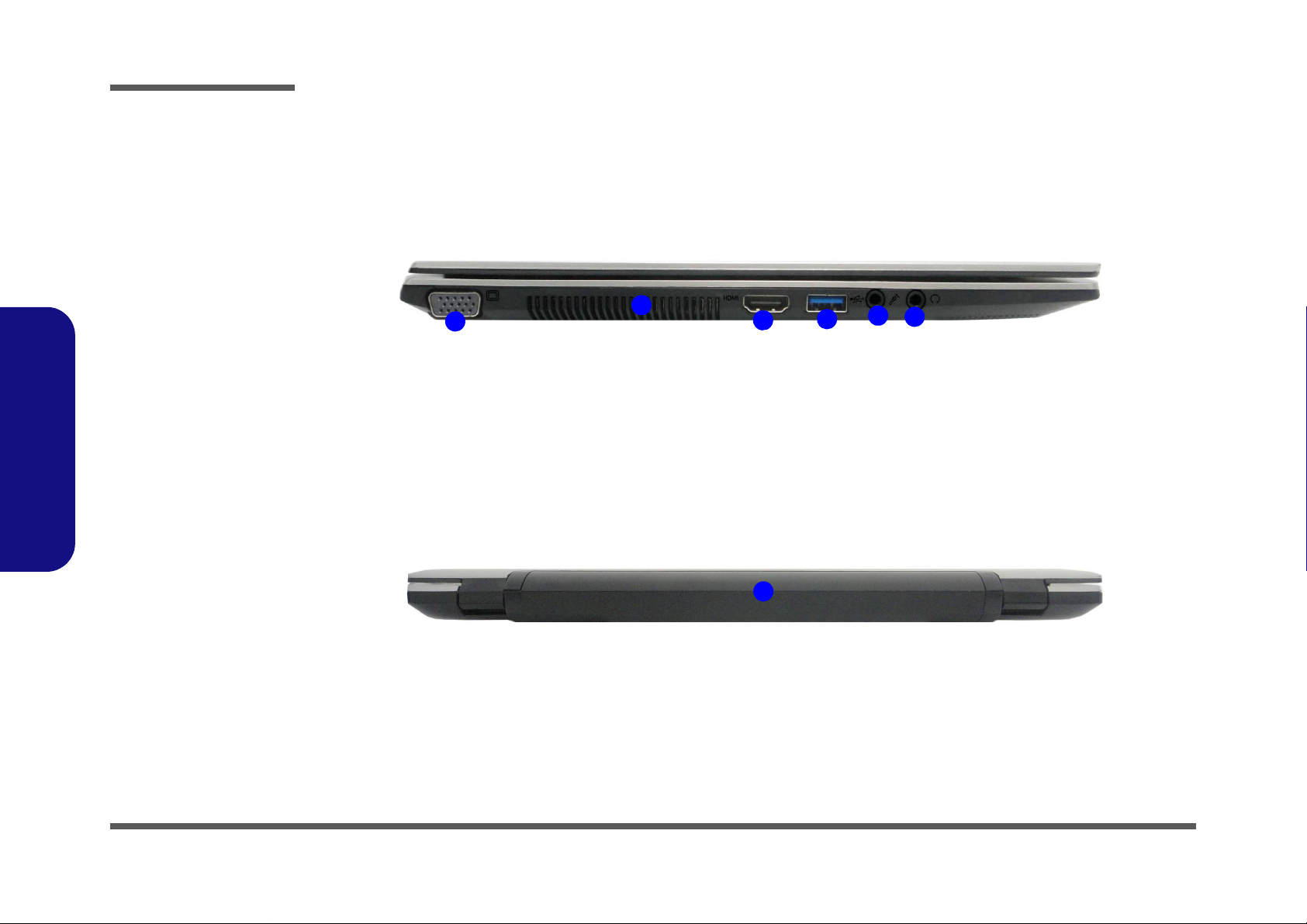
Figure 4
Left Side View
1. External Monitor
Port
2. Vent
3. HDMI-Out Port
4. USB 3.0 Port
5. Microphone-In
Jack
6. Headphone-Out
Jack
LEFT SIDE VIEW
1
5
3
2
4
6
Figure 5
Rear View
1. Battery
1
REAR VIEW
Introduction
External Locator - Left Side & Rear View
/
1 - 6 External Locator - Left Side & Rear View
External Locator - Bottom View
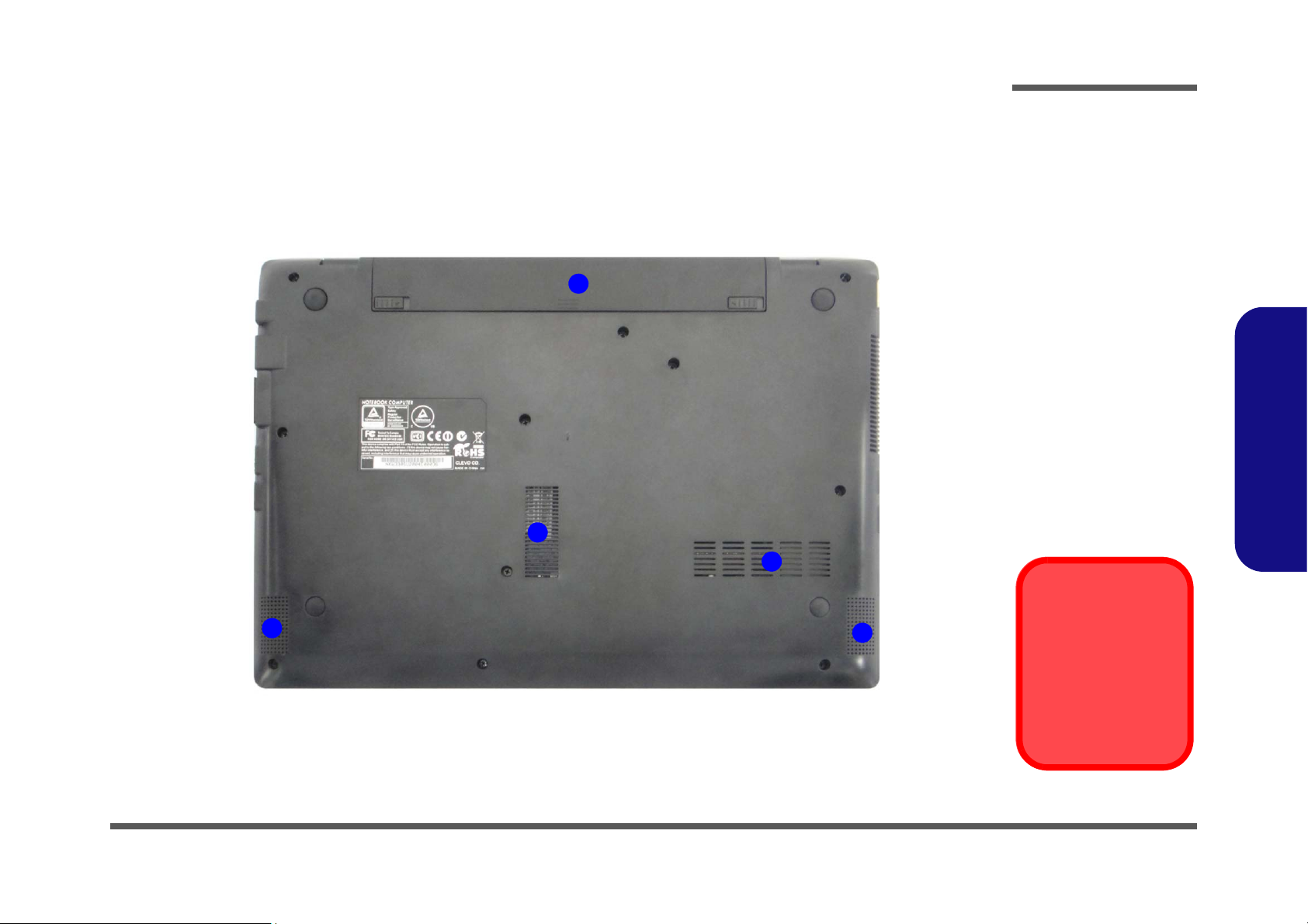
Figure 6
Bottom View
1. Battery
2. Speakers
3. Fan Intake/Vent
Overheating
To prevent your computer from overheating, make sure nothing blocks any vent
while the computer is
in use.
2
1
2
3
3
Introduction
1.Introduction
External Locator - Bottom View 1 - 7
Introduction
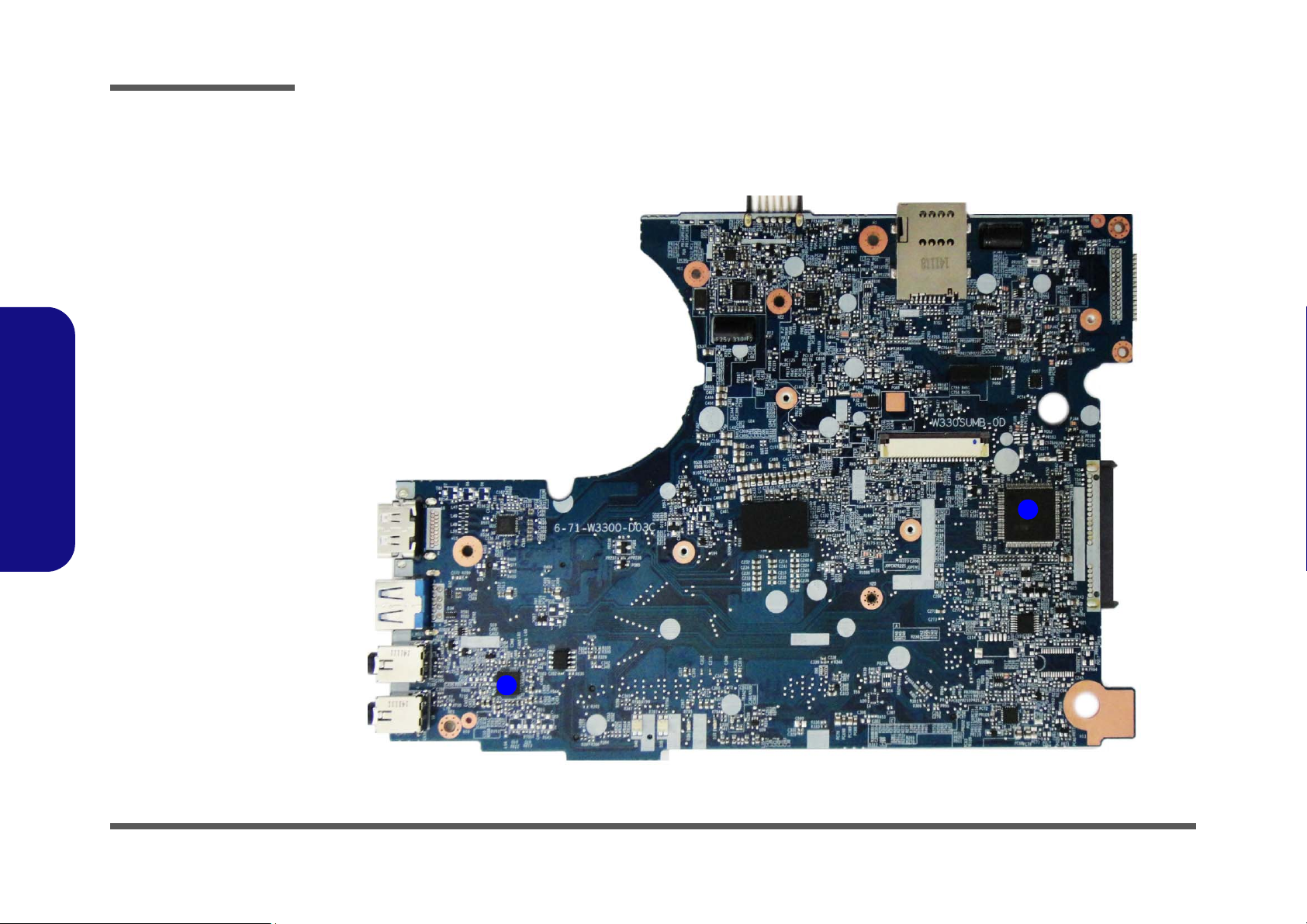
Figure 7
Mainboard Top
Key Parts
1. KBC ITE
IT8587E/FX
2. Audio Codec
ALC2690_VC2
1
2
1.Introduction
Mainboard Overview - Top (Key Parts)
1 - 8 Mainboard Overview - Top (Key Parts)
Mainboard Overview - Bottom (Key Parts)
1
2
3
4
5
2
3
6
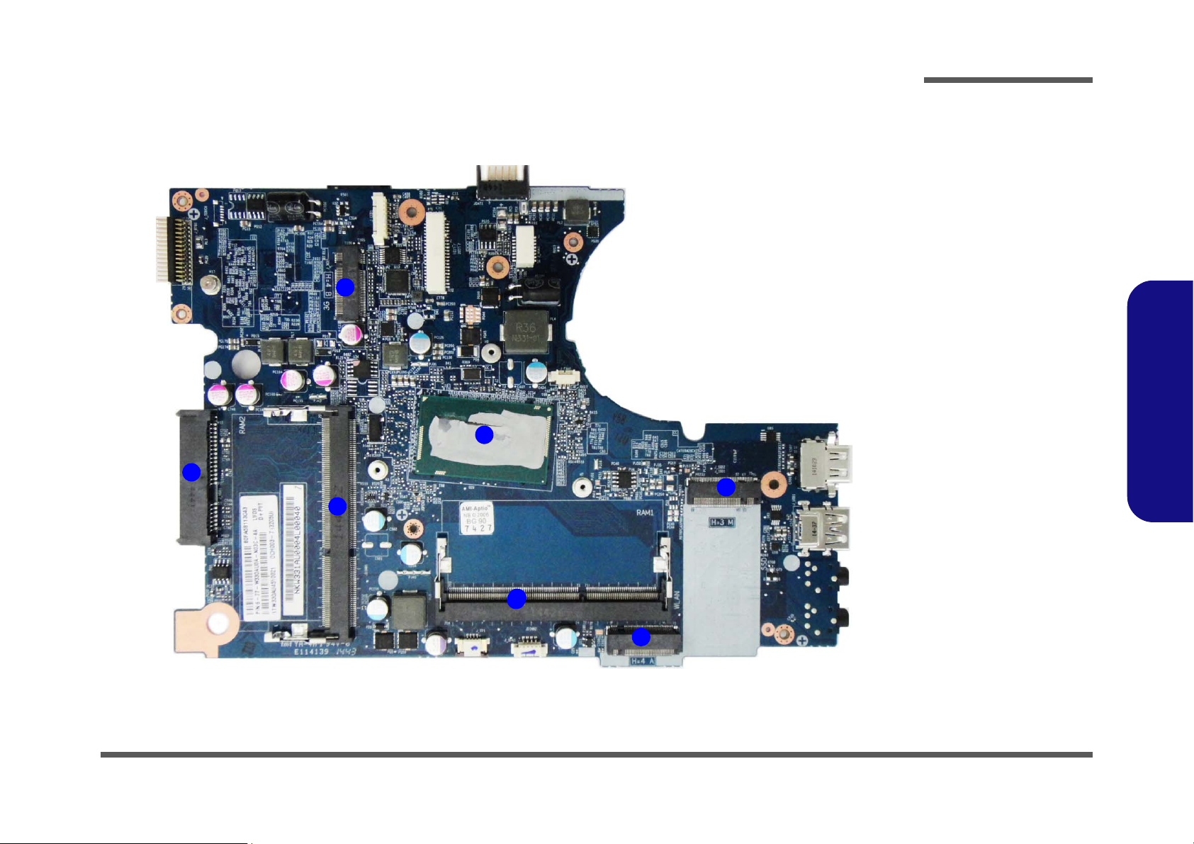
Figure 8
Mainboard Bottom
Key Parts
1. M.2 Conne
ctor
(3G module)
2.
HDD Connector
3.
Memory Slot
DDR3L SO-DIMM
4. CPU
5. M.2 Conne
ctor
(WL
AN Module)
6. M.2 Conne
ctor
(SSD Mo
dule)
Introduction
1.Introduction
Mainboard Overview - Bottom (Key Parts) 1 - 9
Introduction
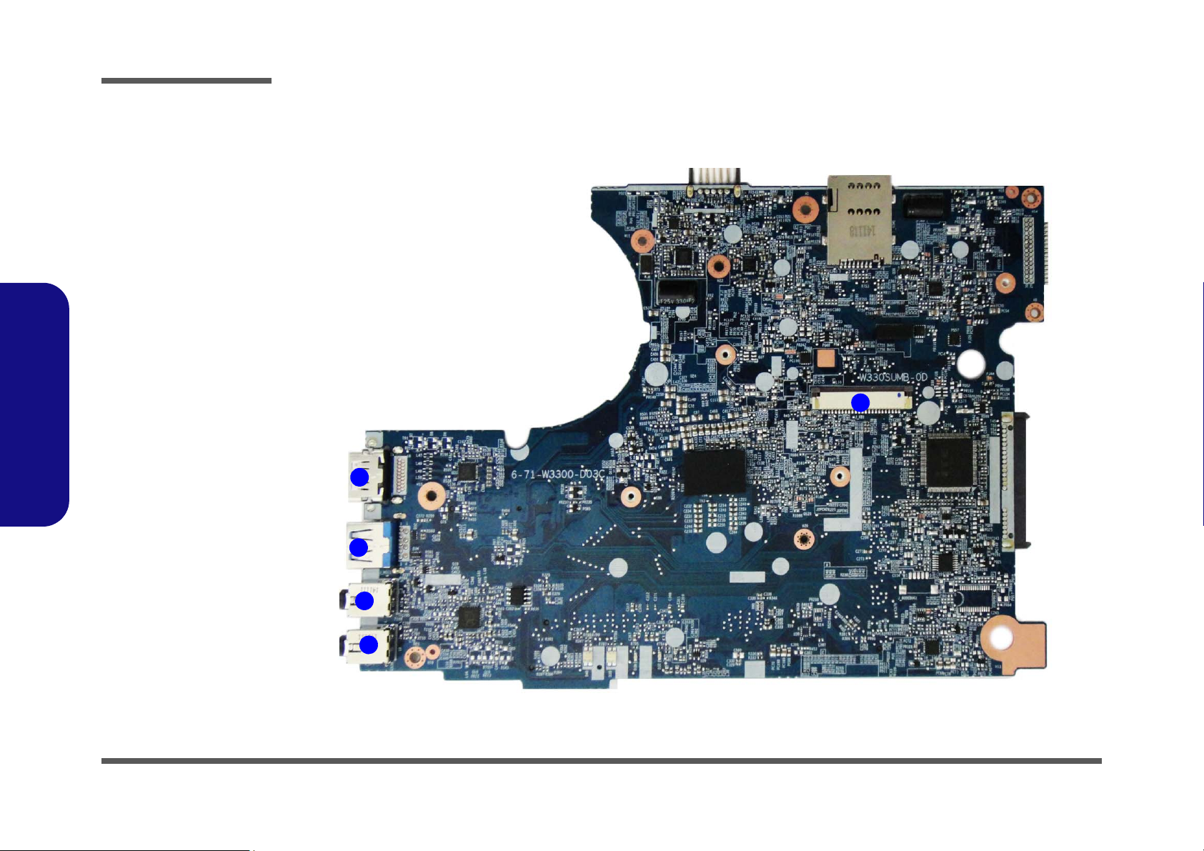
Figure 9
Mainboard Top
Connectors
1. Keyboard Ca
ble
Conn
ector
2. HDMI-Out Port
3. USB 3.0 Port
4. Microphon
e-In
Jac
k
5. Headph
one-Out
Jac
k
5
1
2
3
4
Mainboard Overview - Top (Connectors)
1.Introduction
1 - 10 Mainboard Overview - Top (Connectors)
Mainboard Overview - Bottom (Connectors)
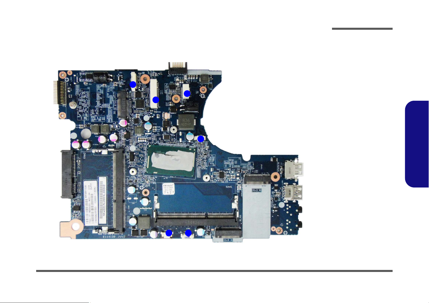
Figure 10
Mainboard Bottom
Connectors
1.
CCD Cable
Conn
ector
2. LCD Connector
3.
Power Switch
Conn
ector
4. Fan Cable
Connector
5. Touchpad
Connector
6. Spea
ker
Conn
ector
10
1
2
4
5
3
6
Introduction
1.Introduction
Mainboard Overview - Bottom (Connectors) 1 - 11
3. Battery
12634
a.
3
b.
2
4
1
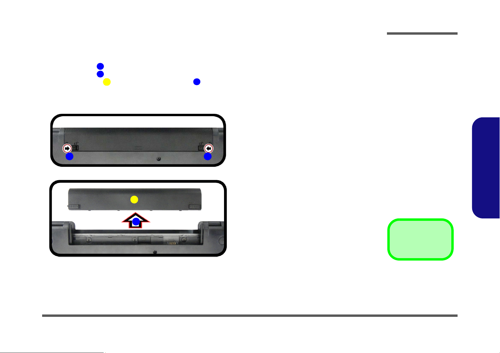
Figure 1
Battery Removal
a. Slide the latch and hold in
place.
b. Slide the battery in the di-
rection of the arrow.
Removing the Battery
1. Turn the computer off, and turn it over.
2. Slide the latch in the direction of the arrow (Figure 1a
3. Slide the latch in the direction of the arrow, and hold it in place (Figure 1a
4. Slide the battery in the direction of the arrow (Figure 1b
).
).
Disassembly
).
2.Disassembly
Removing the Battery 2 - 5
Disassembly
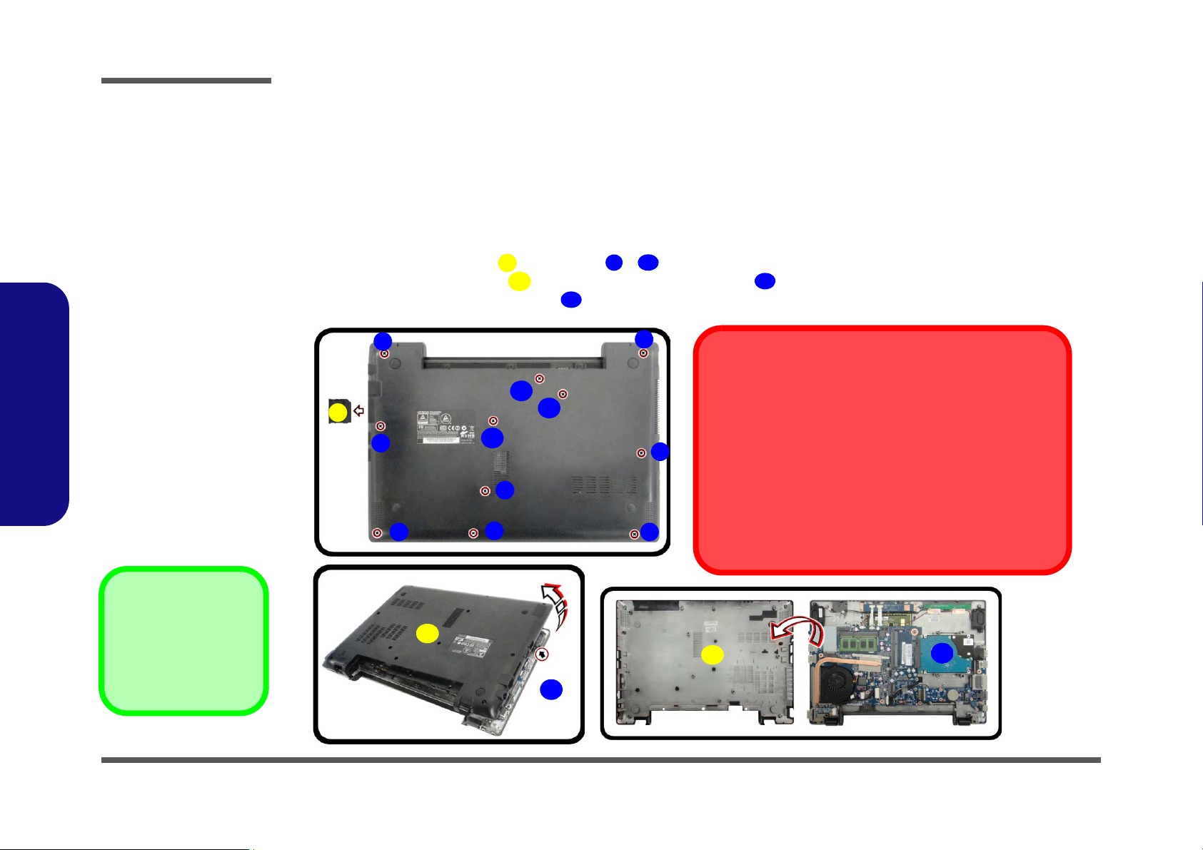
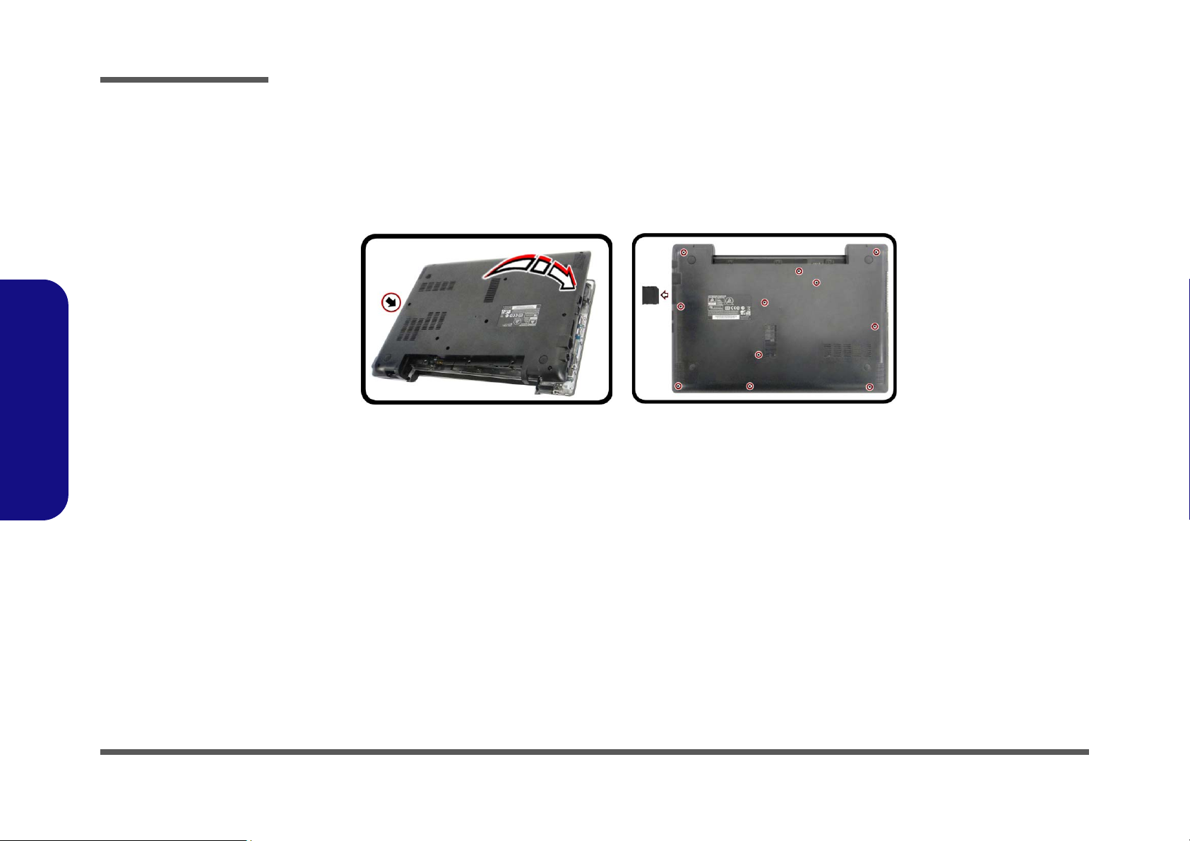
Figure 2
HDD Assembly
Removal
a. Remove the cover and
screws.
b. Remove the bottom case
and locate the hard disk.
1. SD Card Cover
13.Bottom case
•15 Screws
612
121314
15
HDD System Warning
New HDD’s are blank. Before you begin make sure:
You have backed up any data you want to keep from your old
HDD.
You have all the CD-ROMs and FDDs required to install your
operating system and programs.
If you have access to the internet, download the latest appli-
cation and hardware driver updates for the operating system
you plan to install. Copy these to a removable medium.
a.
b.
2
4
3
7
8
5
6
1
13
14
9
10
11
12
15
13
Removing the Hard Disk Drive
The hard disk drive can be taken out to accommodate other 2.5" serial (SATA) hard disk drives with a height of 7mm
(h) and a speed of 5400 RPM or lower. Follow your operating system’s installation instructions, and install all necessary
drivers and utilities (as outlined in Chapter 4 of the User’s Manual) when setting up a new hard disk.
2.Disassembly
Hard Disk Upgrade Process
1. Turn off the computer and remove the battery (page 2 - 5).
2. Remove the SD card cover and screws - (Figure 2a
Carefully lift the bottom
3.
case
up in the direction of the arrow and remove it (Figure 2b).
4. The hard disk will be visible at point on the computer. (Figure 2b
).
)
2 - 6 Removing the Hard Disk Drive
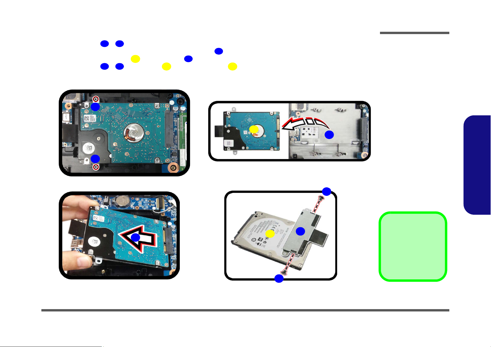
5. Remove screws - from the HDD assembly (Figure 3c).
16171819202122
23
24
19.HDD Assembly
23.HDD Bracket
24.HDD
•2 Screws
Figure 3
HDD Assembly
Removal (cont’d.)
c. Remove the screws.
d. Slightly lift and pull the
HDD in the direction of
the arrow.
e. Lift the HDD assembly
out of the bay.
f. Remove the screws and
bracket from the HDD.
c.
f.
24
16
d.
18
e.
19
20
17
22
21
23
6. Slightly lift and pull the hard disk in the direction of arrow (Figure 3d).
7. Lift the hard disk assembly out of the bay (Figure 3e).
8. Remove screws
- and bracket from the hard disk (Figure 3f).
9. Reverse the process to install a new hard disk (do not forget to replace all the screws and cover).
Disassembly
2.Disassembly
Removing the Hard Disk Drive 2 - 7
Disassembly
1
23445
3
11
a.
b.
2
5
3
c.
4
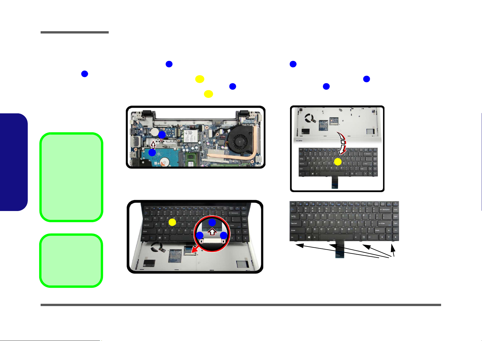
Keyboard Tabs
5
d.
1
3
Re-Inserting the Key-
board
When re-inserting the
keyboard, align first
the four keyboard tabs
(Figure 4d) that are located at the bottom, to
the slots in the case.
Figure 4
Keyboard Removal
a. Remove screw abd
press at point to release the keyboard.
b. Lift the keyboard up and
disconnect the cable
from the locking collar.
c. Remove the keyboard.
1
3. Keyboard
•1 Screw
Removing the Keyboard
1. Turn off the computer, remove the battery (page 2 - 5), and bottom case (page 2 - 6).
2. Remove screw
(Figure 4a).
3. Carefully lift the keyboard
4. Disconnect the keyboard ribbon cable from the locking collar socket
5. Carefully lift up the keyboard
and carefully press the keyboard at point to elevate the keyboard from its normal position
up, being careful not to bend the keyboard ribbon cable (Figure 4b).
(Figure 4b)
(Figure 4c) off the computer.
2.Disassembly
2 - 8 Removing the Keyboard
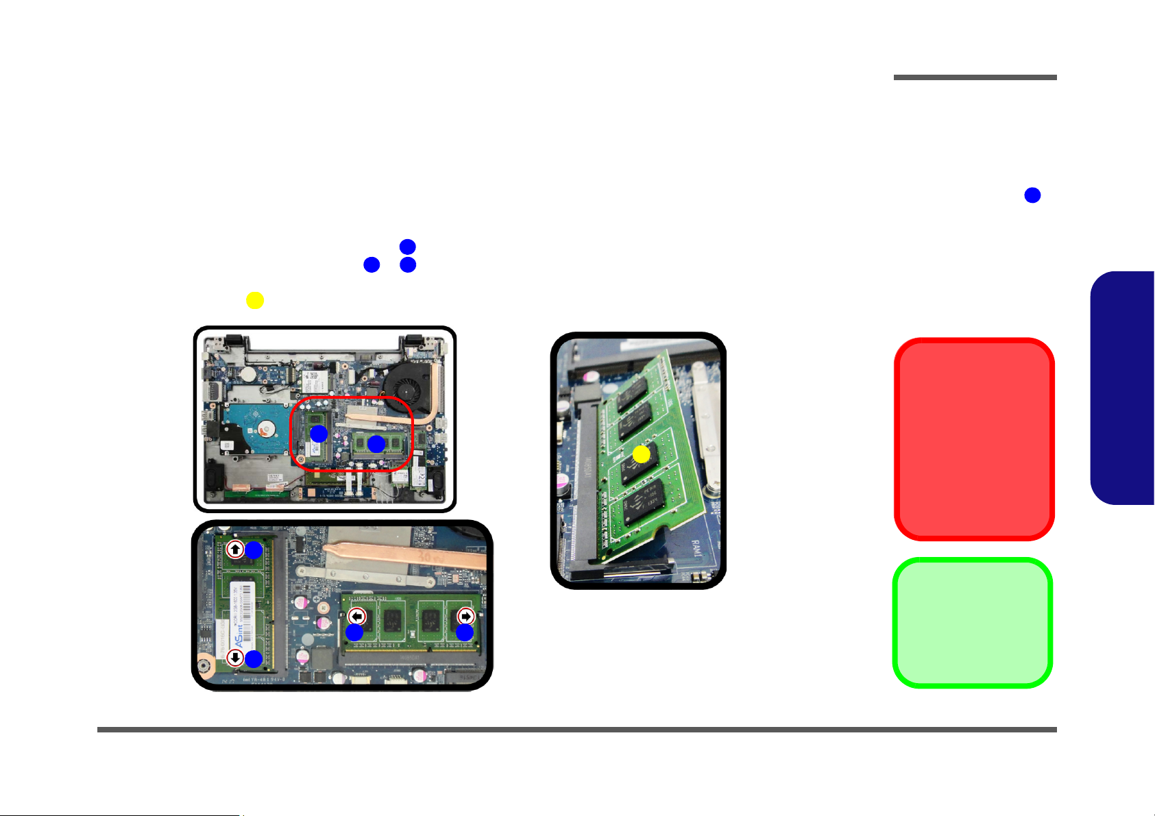
Removing the System Memory (RAM)
Figure 5
RAM Module
Removal
a. The RAM modules will
be visible at point
on the mainboard.
b. Pull the release lat-
ches.
c. Remove the module.
Contact Warning
Be careful not to touch
the metal pins on the
module’s connecting
edge. Even the cleanest
hands have oils which
can attract particles, and
degrade the module’s
performance.
1
4. RAM Module
123
6
4
a.
b.
1
c.
4
32
1
2
3
The computer has two memory sockets for 204 pin Small Outline Dual In-line Memory Modules (SO-DIMM) supporting
DDR3L up to 1600MHz. The total memory size is automatically detected by the POST routine once you turn on your
computer.
Memory Upgrade Process
1. Turn off the computer, remove the battery (page 2 - 5), and bottom case (page 2 - 6).
2. The RAM modules will be visible at point on the mainboard (Figure 5a).
3. Gently pull the two release latches ( & ) on the sides of the memory socket in the direction indicate
4. The RAM module will pop-up
arrows (Figu
re 5b).
Disassembly
d by the
(Figure 5c), and you can then remove it.
2.Disassembly
Removing the System Memory (RAM) 2 - 9
Disassembly
d.
Figure 6
RAM Module
Removal (cont’d)
d. Replace the bottom
case and tighten the
screws.
2.Disassembly
5. Insert a new module holding it at about a 30° angle and fit the connectors firmly into the memory slot.
6. The module will only fit one way as defined by its pin alignment. Make sure the module is seated as far into the slot
as it will go. DO NOT FORCE IT; it should fit without much pressure.
7. Press the module in and down towards the mainboard until the slot levers click into place to secure the module.
8. Replace the bottom case and tighten the screws and cover (Figure 6d)
9. Restart the computer to allow the BIOS to register the new memory configuration as it starts up.
.
2 - 10 Removing the System Memory (RAM)
Removing the Wireless LAN Module
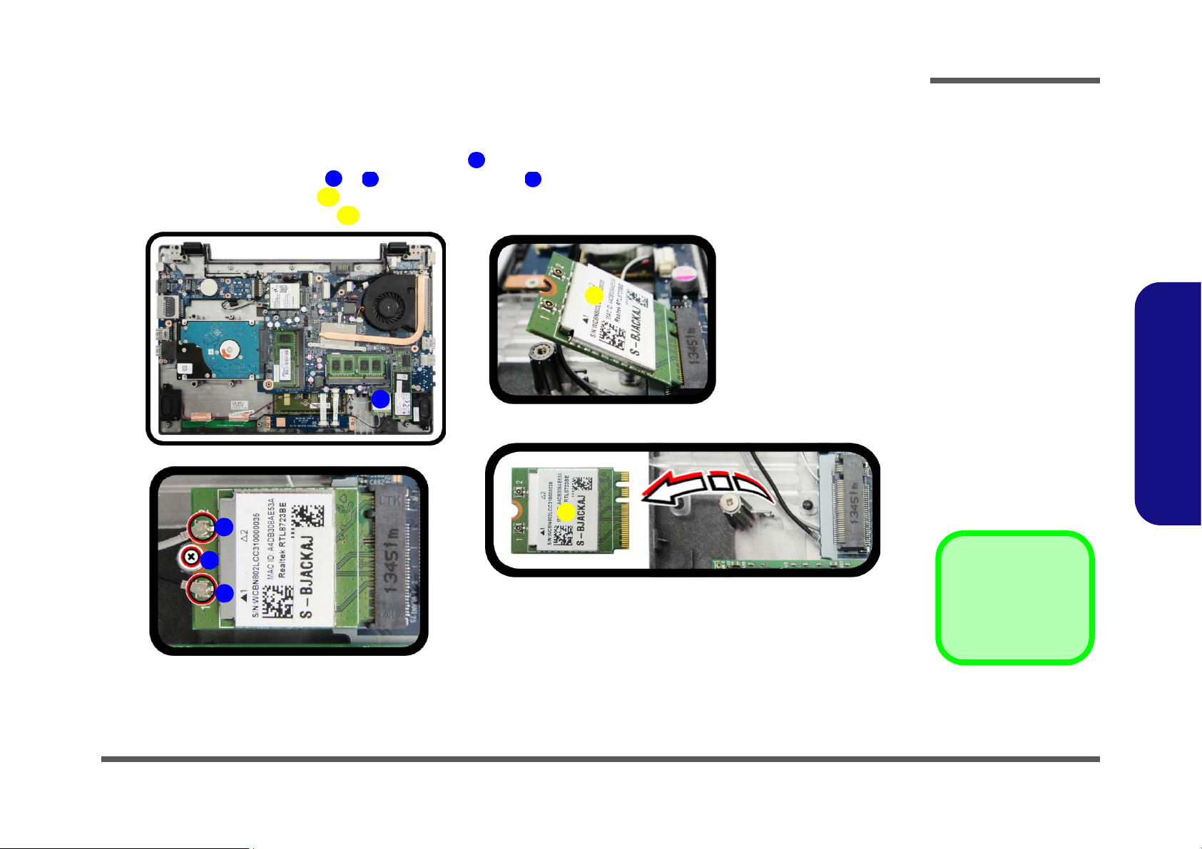
Figure 7
Wireless LAN
Module Removal
a. Locate the wirel ess LAN
module.
b. Disconnect the cables
and remove the screw.
c. The WLAN module will
pop up.
d. Lift the WLAN module
out.
Note: Make sure you
reconnect the antenna
cable to ‘’1’’ +
‘’2’’socket (Figure
b).
1
2
3
4
5
5
5
4
b.
a.
2
3
1
5
d.
c.
5. WLAN Module.
•1 Screw
1. Turn off the computer, remove the battery (page 2 - 5), and bottom case (page 2 - 6).
2. The Wireless LAN module will be visible at point (Figure 7a
3. Carefully disconnect cables & , then remove screw from the module socket (Figure 7b
4. The Wire
5. Lift the Wireless LAN modu
less LAN module
(Figure 7c) will pop-up.
le
(Figure 7d) up and off the computer.
) on the mainboard.
Disassembly
).
2.Disassembly
Removing the Wireless LAN Module 2 - 11
Disassembly
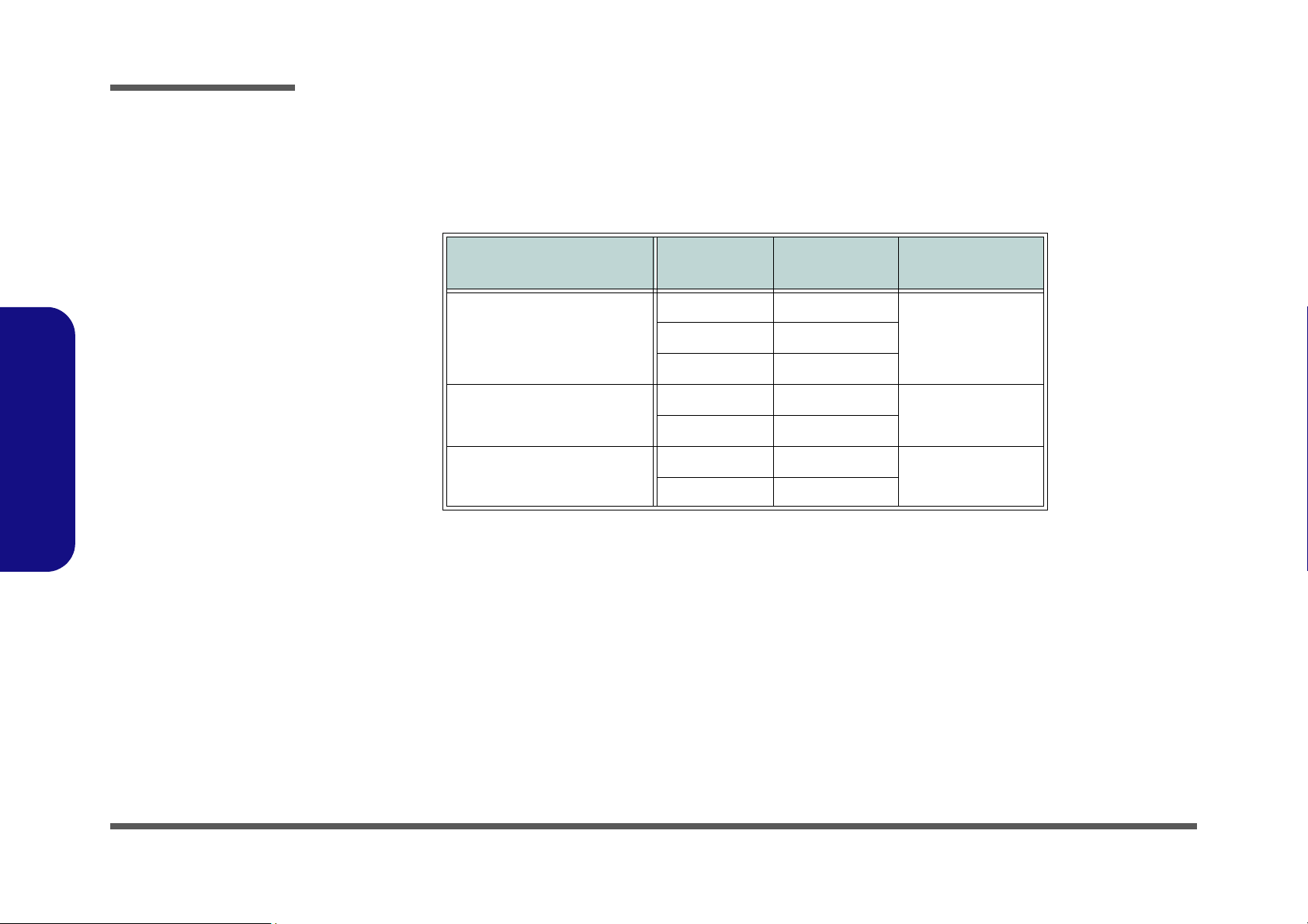
Wireless LAN, and Combo Module Cables
Note that the cables for connecting to the antennae on WLAN, WLAN & Bluetooth Combo, 3G and LTE modules are
not labelled. The cables/covers (each cable will have either a black or transparent cable cover) are color coded for identification as outlined in the table below.
2.Disassembly
Module Type
WLAN/WLAN & Bluetooth
Combo
LTE Broadband
3G Broadband
Antenna
Type
WM 1 Black
WM 3 White
LTE 1 Black
LTE 2 Gray
3G 1 Black
3G 2 Gray
Cable Color
Cable Cover
Type
TransparentWM 2 Gray
Black
Black
Cable 1 is usually connected to antenna 1 (Main) on the module, and cable 2 to antenna 2 (Aux).
2 - 12 Wireless LAN, and Combo Module Cables
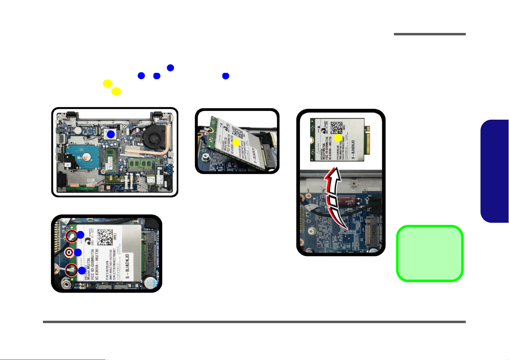
Removing the 3G Module
Figure 8
3G Module Removal
a. Locate the 3G module.
b. Disconnect the cables
and remove the screw.
c. The 3G module will pop
up.
d. Lift the 3G module out.
Note: Make sure you
reconnect the antenna
cable to ‘’1’’ +
‘’2’’socket (Figure
b).
1
2
3
4
5
5
5
4
b.
a.
2
3
1
5
d.
c.
5. 3G Module.
•1 Screw
1. Turn off the computer, remove the battery (page 2 - 5), and bottom case (page 2 - 6).
2. The 3G module will be visible at point (Figure 7a
3. Carefully disconnect cables & , then remove screw from the module socket (Figure 7b
4. The 3G modu
5. Lift the 3G
le
module
(Figure 7c) will pop-up.
(Figure 7d) up and off the computer.
) on the mainboard.
Disassembly
).
2.Disassembly
Removing the 3G Module 2 - 13
Disassembly
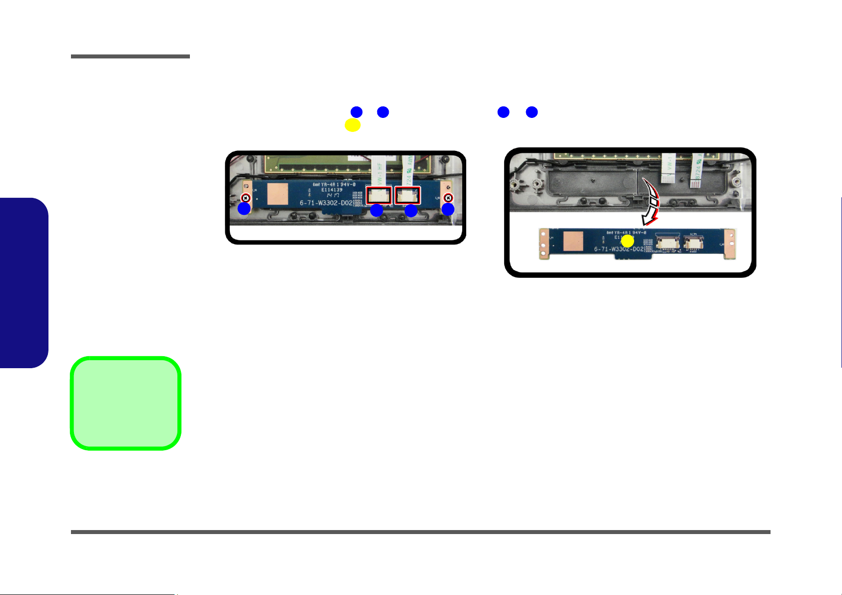
Figure 9
Click Board Module
Removal
a. Disconnect the cables
and remove the screw.
b. Lift the click board out.
123
4
5
5. Click Board Module
•2 Screws
a.
2
3
1
5
b.
4
Removing the Click Board Module
1. Turn off the computer, remove the battery (page 2 - 5), and bottom case (page 2 - 6).
2. Carefully disconnect cables & , then remove screws
3. Lift the click board module (Figure 7b) up and off the computer.
& from the module (Figure 7a).
2.Disassembly
2 - 14 Removing the Click Board Module
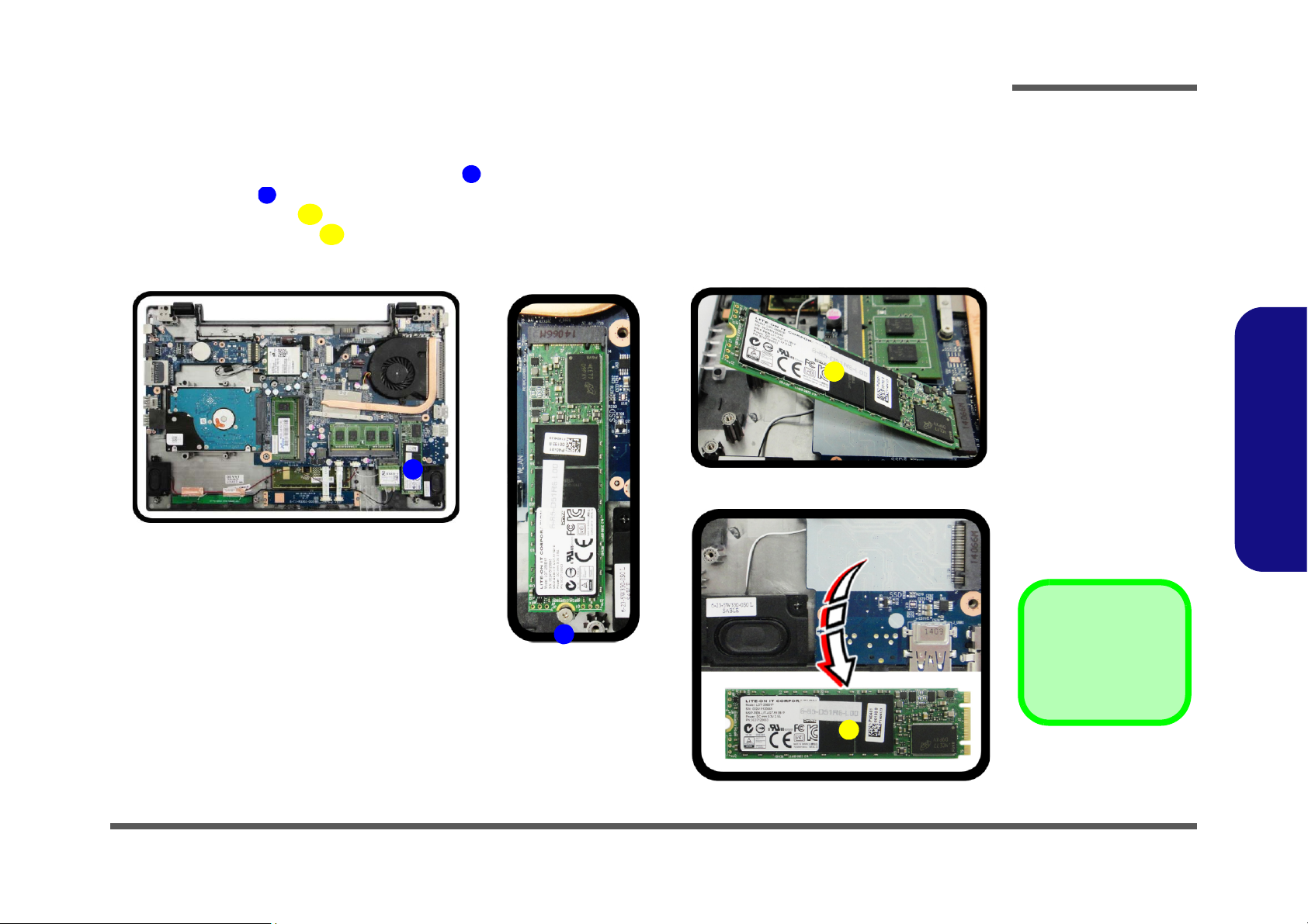
Removing the mSATA Module
Figure 10
mSATA Module
Removal
a. Locate the mSATA mod-
ule.
b. Remove the screw.
c. The mSATA module will
pop up.
d. Lift the mSATA module
out.
1
2
3
3
3
a.
2
1
3
d.
b.
c.
3. SSD Module.
•1 Screw
1. Turn off the computer, remove the battery (page 2 - 5), keyboard (page 2 - 8), and bottom case (page 2 - 6).
2. The mSATA module will be visible at point (Figure 7a
3. Remove screw from the module socket (Figure 7b
4. The mSAT
5. Lift the mSATA modu
A module
(Figure 7c) will pop-up.
le
(Figure 7d) up and off the computer.
) on the mainboard.
).
Disassembly
2.Disassembly
Removing the mSATA Module 2 - 15
 Loading...