

Page 1
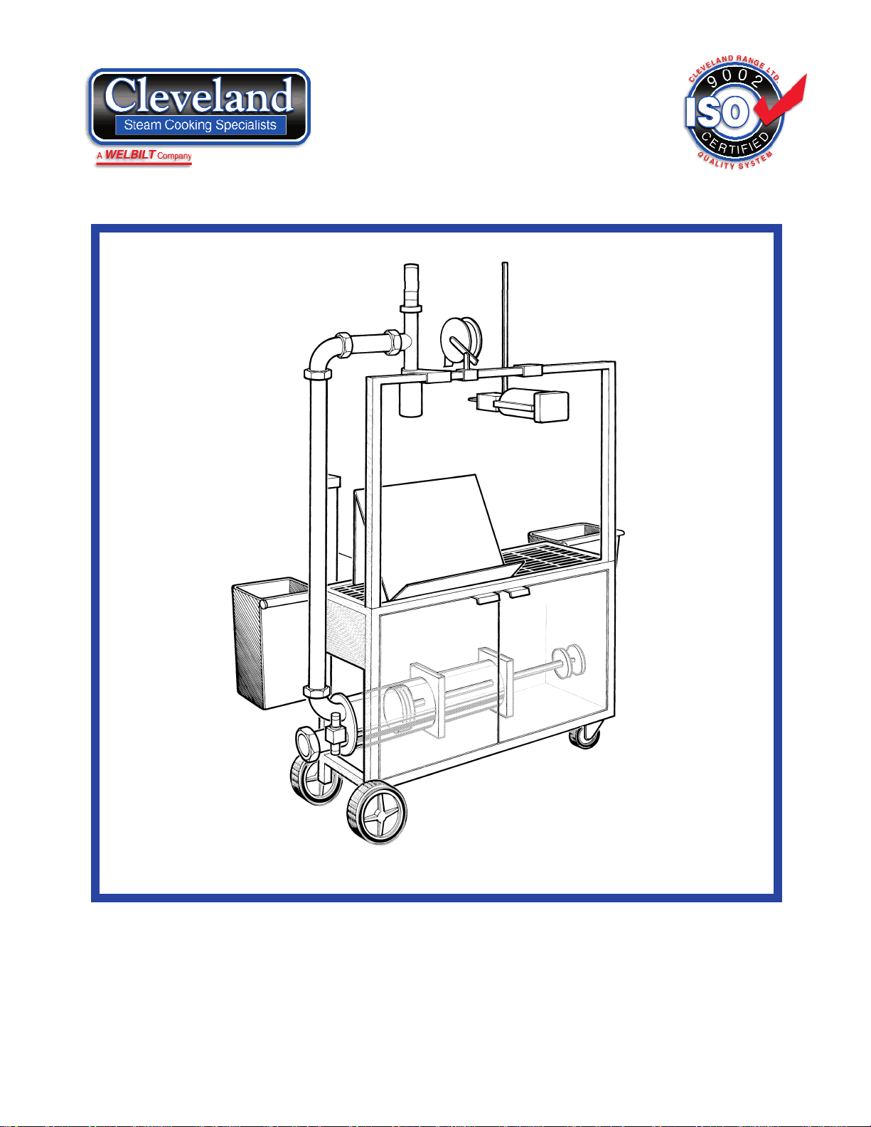
METERING
FILLING
STATION
MODEL: MFS
(for Models built after June, 1994)
CLEVELAND RANGE INC.
1333 East 179th St.
Cleveland, Ohio
U.S.A. 44110
Toll Free 1-800-338-2204
SE95019 Rev.4
INSTALLATION, OPERATION AND SERVICE MANUAL
Page 2

TABLE OF CONTENTS
Installation Inspection. . . . . . . . . . . . . . . . . . . . . . . . . . . . . . . . . . . . . . . . . . . 1
Shipping Damage Instructions . . . . . . . . . . . . . . . . . . . . . . . . . . . 1
Packaged Items . . . . . . . . . . . . . . . . . . . . . . . . . . . . . . . . . . . . . . 1
Assembly . . . . . . . . . . . . . . . . . . . . . . . . . . . . . . . . . . . . . . . . . . . 1
Clipper. . . . . . . . . . . . . . . . . . . . . . . . . . . . . . . . . . . . . . . . . . . . . 1
Installation Requirements - Compressed Air & Electrical . . . . . . . 1
Installation Checks. . . . . . . . . . . . . . . . . . . . . . . . . . . . . . . . . . . . 2
Operating Instructions General Parts Drawing . . . . . . . . . . . . . . . . . . . . . . . . . . . . . . . . 3
Operating Controls . . . . . . . . . . . . . . . . . . . . . . . . . . . . . . . . . . . . 3
Pumping. . . . . . . . . . . . . . . . . . . . . . . . . . . . . . . . . . . . . . . . . . . . 4
Approximate Volume Setting Instructions . . . . . . . . . . . . . . . . . . . 4
Cleaning Instructions Preproduction Sanitizing Procedure . . . . . . . . . . . . . . . . . . . . . . . 5
Flushing . . . . . . . . . . . . . . . . . . . . . . . . . . . . . . . . . . . . . . . . . . . . 5
Disassembly . . . . . . . . . . . . . . . . . . . . . . . . . . . . . . . . . . . . . . . . . 6
Cleaning . . . . . . . . . . . . . . . . . . . . . . . . . . . . . . . . . . . . . . . . . . 6-7
Assembly . . . . . . . . . . . . . . . . . . . . . . . . . . . . . . . . . . . . . . . . . . 7-8
Sanitizing . . . . . . . . . . . . . . . . . . . . . . . . . . . . . . . . . . . . . . . . . . . 8
Service Parts Warranty. . . . . . . . . . . . . . . . . . . . . . . . . . . . . . . . . . . . . . . . . . . . 9
Piston Head Assembly . . . . . . . . . . . . . . . . . . . . . . . . . . . . . . . . . 9
Pump Assembly. . . . . . . . . . . . . . . . . . . . . . . . . . . . . . . . . . . . . . 10
Label Dispenser . . . . . . . . . . . . . . . . . . . . . . . . . . . . . . . . . . . . . 11
Hose Assemblies. . . . . . . . . . . . . . . . . . . . . . . . . . . . . . . . . . . . . 12
Thermal Assurance Package (option) . . . . . . . . . . . . . . . . . . . . . 13
Miscellaneous Parts . . . . . . . . . . . . . . . . . . . . . . . . . . . . . . . . . . 14
Piping Assemblies, "O" Rings, Gaskets & Seals. . . . . . . . . . . 15-16
"O" Rings, Gaskets & Seals (shown actual size) . . . . . . . . . . 17-18
Maintenance Air Pressure . . . . . . . . . . . . . . . . . . . . . . . . . . . . . . . . . . . . . . . . 19
Oil Filling Procedure . . . . . . . . . . . . . . . . . . . . . . . . . . . . . . . . . 19
Air Filter Replacement Procedure. . . . . . . . . . . . . . . . . . . . . . . . 19
Product Piston Timing . . . . . . . . . . . . . . . . . . . . . . . . . . . . . . . . 19
Adjustment & Setting of Air Cushion Equipped Pump Heads . . . 20
Trouble Shooting Guide . . . . . . . . . . . . . . . . . . . . . . . . . . . . . . . 20
Pneupak Trouble Shooting Guide . . . . . . . . . . . . . . . . . . . . . . . . 21
Pneumatic Schematic . . . . . . . . . . . . . . . . . . . . . . . . . . . . . . . . . 22
Air Package Parts Drawing . . . . . . . . . . . . . . . . . . . . . . . . . . . . 23
Air Package Parts Drawing Legend . . . . . . . . . . . . . . . . . . . . . . 24
Point to Point Air Tubing Connections . . . . . . . . . . . . . . . . . . . . 23
Air Tube Connections . . . . . . . . . . . . . . . . . . . . . . . . . . . . . . 25-26
Spare Parts Lists. . . . . . . . . . . . . . . . . . . . . . . . . . . . . . . . . . . . . 27
Page 3

INSPECTION
Before unpacking visually inspect the unit for
evidence of damage during shipping.
If damage is noticed, do not unpack the unit,
follow shipping damage instructions.
SHIPPING DAMAGE
INSTRUCTIONS
If shipping damage to the unit is discovered or
suspected, observe the following guidelines in
preparing a shipping damage claim.
1. Write down a description of the damage or the
reason for suspecting damage as soon as it is
discovered. This will help in filling out the claim
forms later.
2. As soon as damage is discovered or
suspected, notify the carrier that delivered the
shipment.
3. Arrange for the carrier's representative to
examine the damage.
4. Fill out all carrier claims forms and have the
examining carrier sign and date each form.
PACKAGED ITEMS
Packaged items that are shipped loose with the
unit include:
(1) 2" Wrench
(1) 3" Wrench
(2) Trash Containers
(1) Assortment of spare "O" Rings
(1) Air Hose Assembly
(2) Food Hose Assemblies
(1) Food Grade Grease
(1) Spring
(1) Bolt
(1) Cleaning Hose
(1) Brush Kit
(1) 3" 90° Elbow
(1) Lug Nut Wrench
ASSEMBLY
The Metering Filling Station is a mobile unit that
requires no assembly to complete unless a clipper
has been shipped with the unit.
It does however ship with a number of loose items
that are required for its use.
These items should be stored in a convenient
location.
CLIPPER
If a clipper is supplied with the unit, it must be
mounted. Remove it from the box and connect it to
the mounting bar using part #FA11509 bolt
(supplied). Connect one end of the short air hose
(supplied) to the clipper and the other end to the
male quick connect on the end of the MFS.
INSTALLATION
REQUIREMENTS
Compressed Air
This unit requires a constant 25 c.f.m. (cubic feet per
minute) at 90 to 100 p.s.i. (pounds per square inch).
The air must be filtered of oil, moisture and dirt.
The dew point of the supply air must be less than
65°F. The Metering Filling Station is equipped with
its' own air oiler system, therefore, no oil should be
added to the supply air. We recommend the
compressed air system be equipped with a drier,
filter, and automatic water dump on the air
compressor receiver tank. If the distance between
the tank and the unit is less than 100 feet then a
minimum line size of 3/4" is required. A distance of
100 to 300 feet requires a minimum 1" line.
Connect one end of air line (supplied) to the
metering filling station and the other end to the
kettle air outlet fitting.
If you do not have a Cleveland kettle with air
connection built-in then you must attach the
female quick connect (supplied) to your air supply.
Electrical
No electrical connection is required unless the unit
comes equipped with a Thermal Assurance
Package (TAP) option. This requires a 115V. 1PH.
grounded outlet.
1
INSTALLATION
Page 4

INSTALLATION CHECKS
(see General Parts Drawing, page 3)
AIR PRESSURE
Complete the following steps with the 3" dia. Food
Product Hose (15) not connected:
1. Connect supply air to metering filling station.
2. Open front Access Doors (17) on metering
filling station.
3. Set Stroke Selection Switch on Control Panel
(1) for "CONSTANT PUMPING".
4. Hold Trigger Lever (10) and read Pressure
Gauge (21) as pump is operating. Pressure
should not drop less than 90 psi or exceed
110 psi.
5. Adjust Pressure Regulator Dial (20) or supply
pressure if required.
Note: If there is no air to unit check:
A/ The kettle's Air Quick Connect is
pushed upward to the "OPEN" position.
Air Quick Connect on Mixer Kettle
B/ Open the back Access Doors (17) and check
that the Main Air Shut Off Valve (22) is
pressed inwards.
SINGLE STROKE
Note: Use 3" gaskets in all hex nut couplings on
food hose.
⇒ First, hand-tighten.
⇒ Then, snug with wrench.
1. Using 3" gasket, connect the 3" dia. Food
Product Hose (15) to metering filling station
and kettle.
2. Add water to kettle and open kettle's product
discharge valve.
3. Open front Access Doors (17) of metering
filling station.
4. Set Stroke Selection Switch on Control Panel
(1) for "SINGLE STROKE".
5. Place bag over Discharge Nozzle (11).
6. Pull and hold Trigger Lever (10).
7. Product piston should go all the way forward,
then return and stop.
8. Release Trigger Lever (10).
9. Repeat test two to four times, product will start
to discharge into bag.
CLIPPER
Refer to clipper operating instruction manual for
safety and operating procedures.
2
OPEN
Page 5
OPERATING INSTRUCTIONS
3
OPERATING CONTROLS
NAME FUNCTION
Discharge speed Adjusts speed of product exiting
the discharge nozzle.
Suction speed Adjusts speed of product being
pulled from kettle and into pump.
Stroke selection Selects operating mode or OFF
when not in use.
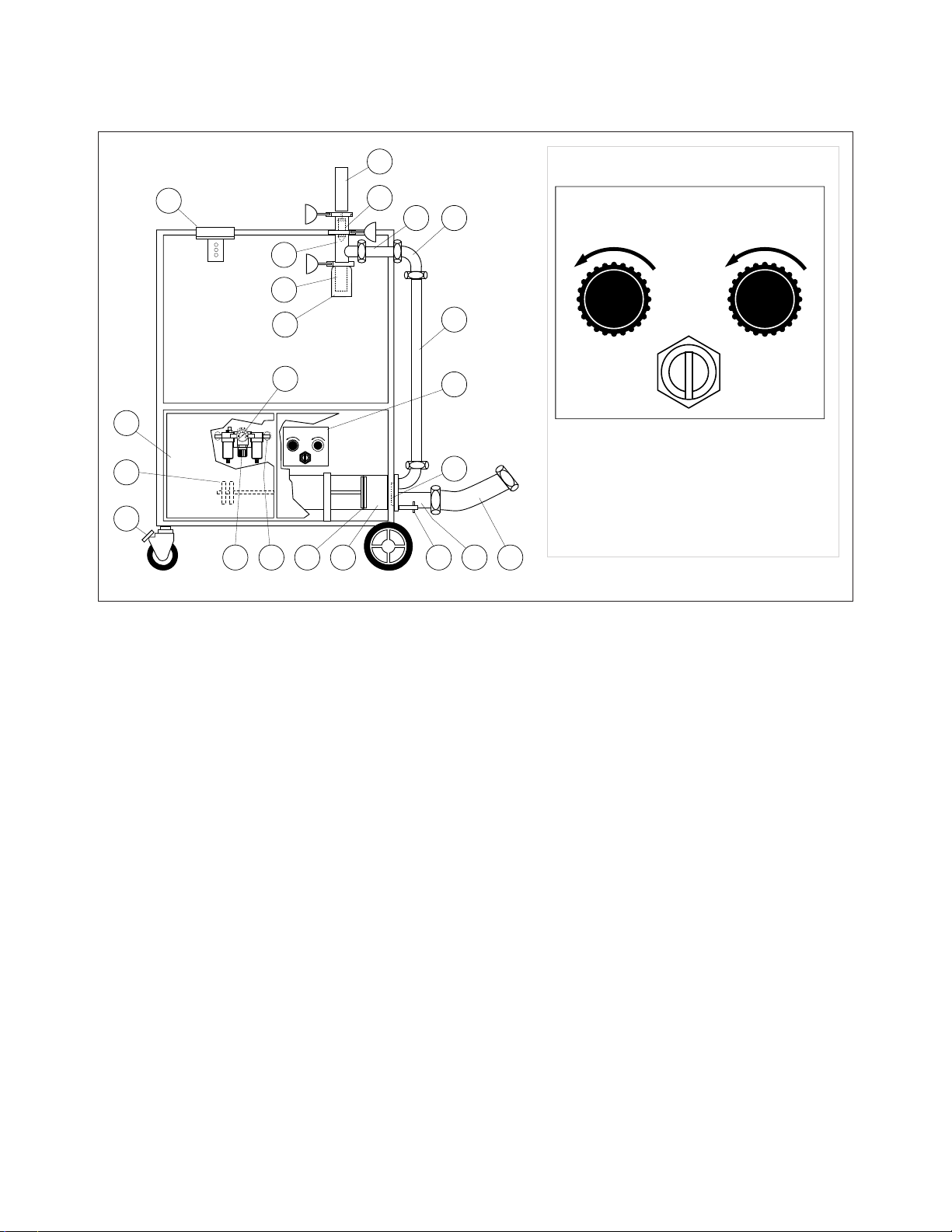
General Parts Drawing
ITEM # DESCRIPTION FUNCTION
1. Control Panel . . . . . . . . . . . . . . . Includes: A/ speed adjusters for suction and discharge.
B/ stroke selection switch.
2. Flapper Valve . . . . . . . . . . . . . . Changes direction of product flow.
3. Piston Head
4. Large Lug Nuts . . . . . . . . . . . . . Holds product head to product cylinder.
5. Product Cylinder . . . . . . . . . . . . Cylinder product is drawn into and discharged from.
6. Product Piston . . . . . . . . . . . . . . Moves product within the cylinder.
7. Product Discharge Valve . . . . . . Air cylinder that opens and closes discharge opening
by moving plunger.
8. Plunger . . . . . . . . . . . . . . . . . . . Opens and closes product discharge opening.
9. Discharge Valve Body
10. Trigger Lever . . . . . . . . . . . . . . . Activates pumping action.
11. Discharge Nozzle . . . . . . . . . . . Directs the flow of discharge product.
12. 2" dia. Short Connector Pipe
13. 2" Elbow
14. 2" dia. Long Connector Pipe
15. 3" dia. Food Product Hose . . . . . 3" dia. hose to connect Metering Filling Station hose to kettle.
16. Brake . . . . . . . . . . . . . . . . . . . . Locks pump in position.
17. Access Doors
18. Clipper Bracket . . . . . . . . . . . . . Mounting bracket for optional clipper.
19. Adjusting Wheels . . . . . . . . . . . . Used for setting desired pumping volume.
20. Pressure Regulator Dial . . . . . . . Used to regulate air pressure.
21. Pressure Gauge . . . . . . . . . . . . Shows operating pressure.
22. Main Air Shut Off Valve . . . . . . .
Disconnects air supply to unit. (Back side of Metering Filling Station)
18
17
19
16
2220
9
10
11
21
DISCHAR GE
SPEED
FAST SLOW F AST SLOW
2
1
0
9
8
7
SINGLE STROKE CONSTA NT PUMPING
Cleveland
3
4
5
STROKE
6
SELECTI ON
OFF
7
8
12
13
FA ST SL OW FA ST SL OW
14
Cleveland
DI SC HA RG E
SP EE D
ST RO KE
SE LE CT IO N
SI NGLE STR OKE C ONS TANT PUM PING
O F F
SU CT IO N
SP EE D
1
SUCTION
SPEED
2
1
3
0
4
9
5
8
6
7
2
4 36 5 15
Page 6
PUMPING
Note: Use 3" gaskets in all hex nut couplings on
food hose.
⇒ First, hand-tighten.
⇒ Then, snug with wrench.
1. Using 3" gasket, connect one end of the 3"
dia. Food Product Hose (15) to kettle.
2. Position metering filling station for ease of
operation and connect other end of 3" dia.
Food Product Hose (15) - if required use 3"
90° elbow.
3. Connect air hose to kettle and metering filling
station.
4. Open the back Access Doors (17) and check
that the Main Air Shut Off Valve (22) is
pressed inwards.
5. Open front Access Doors (17) of metering
filling station.
6. Set Stroke Selection Switch on Control Panel
(1) for "SINGLE STROKE".
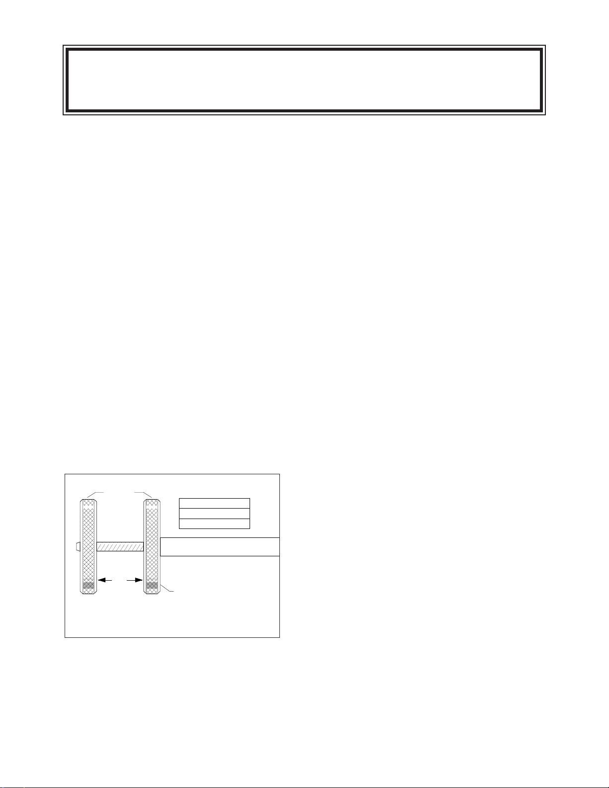
Approximate Volume Setting Instructions
7. Using a ruler, set desired quantity by measuring
between Adjusting Wheels for correct setting.
8. Open product discharge valve on kettle.
9. Place bag over Discharge Nozzle (11).
10. With Stroke Selection Switch on Control Panel
(1) set on "SINGLE STROKE", pull and hold
Trigger Lever (10) against Discharge Nozzle
(11) until pump has stopped; if a second
stroke is required, repeat process.
11. Move bag over to clipper and clip closed
(refer to clipper operating instruction manual).
12. Pump a couple of bags to check volume and
speed.
⇒ To adjust volume, measure between
Adjusting Wheels (19) for correct setting.
⇒ To adjust speed, turn Discharge Speed or
Suction Speed on Control Panel (1) as
required.
⇒ Adjust pump speed faster for thinner
products and slower for thicker.
13. Continue pumping until all product has been
emptied from kettle.
Adjusting
Wheels
A
Locked Position
A Volume
1 1/2" = 1 gallon
3 1/2" = 3 quarts
5 1/2" = 5 quarts
NOTE: Fine tune the distance during start up training.
Make a template for ease of adjustment.
Approximate
4
AS A SAFETY FEATURE THE DISCHARGE NOZZLE (11) WILL
AUTOMATICALLY CLOSE AND THE PUMP WILL REVERSE ANY TIME
YOU RELEASE THE TRIGGER LEVER (10).
Page 7
PREPRODUCTION
SANITIZING PROCEDURE
1. Fill kettle to hemisphere and start the agitator.
2. Add 5.25% bleach to make a 50 ppm solution
- refer to chart.
Amount of water
Amount (5.25%) of
in the kettle bleach to add
20 gal / 76L. . . . 5 tbsp / 75ml
30 gal / 114L. . . . 7 1/2 tbsp / 113ml
40 gal / 151L. . . . 10 tbsp (5/8 cup) / 150ml
50 gal / 190L. . . . 12 1/2 tbsp. (3/4 cup + 1 tbsp) / 188ml
60 gal / 227L. . . . 1 cup / 225ml
Sanitizing Solution Chart
3. Bring the temperature to 80°F (max.- 100°F)
or lukewarm.
NOTE:
Do NOT allow solution to get hot.
4. Attach the metering filling station to the kettle
and pump on "CONTINUOUS" setting for one
minute.
5. Finish emptying the kettle by disconnecting
the 3" dia. Food Product Hose and letting the
contents of the Metering Filling Station and
kettle drain. Make sure the 3" dia. Food
Product Hose does not drag on the floor.
FLUSHING
Between Recipes
1. To clean between batches of product, flush
kettle and Metering Filling Station with a
warm water and mild detergent solution from
kettle to loosen and remove food particles.
2. Remove product Discharge Nozzle and
replace it with cleaning hose.
3. Place end of cleaning hose over a drain.
4. Switch stroke selector switch to "CONSTANT
PUMPING".
5. Pull and hold trigger lever against discharge
valve nozzle until kettle has been emptied.
6. Add clean water to kettle, and repeat process
to rinse units.
NOTE:
The metering filling station must be
sanitized prior to the daily production run.
5
CLEANING INSTRUCTIONS
Flapper Valve
"O" Ring
Spring
Large Lug Nut
Flapper
Rotary Actuator
Cylinder Seal
Shaft
Piston Head
Discharge
Head
Assembly
2" Sani
Clamp
Bracket
Product Piston "O" Ring
2" Sani
Clamp
2" Sani
Clamp
Product
Discharge
Nozzle
Piston Cylinder
Product Piston
Discharge Valve
Plunger
Discharge Valve Body
Gasket
Short
2" dia.
Pipe
Long
2" dia.
Pipe
Push
Pin
Product Cylinder Piston Head Assembly
2" dia. Elbow
Gasket
Gasket
3" dia.
Food
Hose
Gasket
Page 8
DISASSEMBLY
Note: Remove "O" rings using a wooden or
plastic picker; do NOT use a sharp object.
Note: Prepare a properly diluted solution of
authorized cleaning solution in a plastic soak
bucket taken from a freshly filled sink to receive
small parts, gaskets, and "O" rings.
1. Move slide valve on kettle's
air quick connect to down
position to vent air from
metering filling station.
Air Quick Connect on Mixer Kettle
2. Disconnect main air line from Metering Filling
Station.
3. Remove air lines (quick-disconnect fittings)
from Discharge Valve.
4. Undo 2" Sani-Clamp, and remove Discharge
Nozzle.
5. With 2" wrench, loosen nut on Discharge Valve
Body and remove Discharge Head Assembly;
place 2" gasket in warm water to soak.
6. To disassemble Discharge
Head Assembly, follow in
order;
⇒ Remove 2" Sani-Clamp that
holds Discharge Head
Assembly together.
⇒ Separate parts by pulling
them apart.
Discharge Head Assembly
⇒ Using a wooden or plastic picker, remove
"O" Rings from plunger.
⇒ Put "O" Rings in warm water to soak; do
NOT submerge discharge valve.
7. With 2" wrench, remove Short 2" dia. Pipe, 2"
dia. Elbow and Long 2" dia. Pipe. Place all
gaskets in soak bucket.
8. Remove two air lines from Rotary Actuator on
Piston Head Assembly.
9. Using lug wrench, unscrew three Large Lug
Nuts, and remove Piston Head Assembly.
10. Dismantle Piston Head Assembly as follows in
order;
Piston Head Assembly
⇒ Push Rotary Actuator toward Piston Head
to remove Flapper, place Flapper in soak
bucket.
⇒ Remove Rotary Actuator, placing small
spring in soak bucket.
⇒ Do NOT submerge Rotary Actuator.
11. Pull product cylinder off product piston.
⇒ Do NOT use pliers or any other tool that
could damage the inside wall of the cylinder.
12. Using plastic or woden picker, remove "O"
ring from Product Piston.
CLEANING
WARNING: Do not submerge Discharge Valve or
Rotary Actuator in water, damage to air cylinders
will result.
⇒ Always turn off equipment power before
using water.
⇒ Never use steel wool for cleaning; particles
may become embedded and rust.
⇒ Clean unit in the following order:
A/ Warm water and mild detergent solution.
B/ Clear rinse.
C/ Properly diluted sanitizing solution (see
Sanitizing Solution Chart) to sanitize after
cleaning.
⇒ Do NOT use chloride cleaners; they may
damage stainless steel surface.
⇒ For difficult cleaning applications, one of
the following can be used: alcohol, baking
soda, vinegar, or a solution of ammonia in
water.
1. Clean all parts (except Discharge Valve and
6
Push yellow tab down to
release air pressure before
disconnecting air hose
Discharge
Valve
Plunger
"O" Rings
Discharge
Valve
Body
2" Sani
Clamps
Piston Head
Flapper Valve
"O" Ring
Flapper
Shaft
Spring
Rotary Actuator
Page 9
Rotary Actuator) with hot soapy water or run
them through the dish washer.
2. Clean the interior of the 2" inch pipes and the
3" dia. food product hose using the brushes
provided.
3. Inspect "O" rings and gaskets for cuts,
distortion, or wear, replace if required.
4. Leave part disassembled overnight.
ASSEMBLY
NOTE: To eliminate any chance of recontamination
of unit, wear sanitary disposable gloves during
reassembly after cleaning.
This startup procedure assumes the unit is fully
disassembled.
1.
Attach Product Cylinder to Piston Cylinder as
follows:
Product Piston/Cylinder Assembly
⇒ Inspect Product Piston "O" Ring (replace if
worn) on Product Piston - lubricate with food
grade grease.
⇒ Push Product Cylinder over Product Piston
and seat firmly in groove (push pin must be
located as illustrated).
2.
Assemble Piston Head Assembly as follows in
order:
Piston Head Assembly
⇒ Inspect Flapper Valve "O" ring on rotary
actuator (replace if worn).
⇒ Lubricate "O" ring with food grade grease and
put on shaft.
⇒ Put Spring on Shaft.
⇒ Slide Rotary Actuator Shaft thru hole in
Piston Head.
⇒ Mount Flapper to Shaft.
3.
Assemble piston and piping as follows in
order:
Note: Use 2" gaskets in all hex nut
couplings.
2" Piping Assembly
⇒ Put Cylinder Seal in place. Lubricate
exposed portion of Cylinder Seal then mount
Piston Head to Product Cylinder, and fasten
in place with large Lug Nuts using lug wrench
for final tightening.
7
Piston Head
Flapper Valve
"O" Ring
Shaft
Spring
Rotary Actuator
Flapper
Push
Pin
Piston Cylinder
Product Piston
Product Piston "O" Ring
Product Cylinder
Gasket
2" dia. Elbow
Short
2" dia.
Pipe
Long
2" dia.
Pipe
Gasket
Gasket
Product Cylinder
Cylinder
Seal
Lug Nut
Piston Head
Page 10

⇒ Attach two 1/4" air lines to Rotary Actuator
(black line on top).
⇒ Reassemble 2" piping (Long 2" dia. Pipe, 2"
dia. Elbow and Short 2" dia. Pipe) on Piston
Head as illustrated using gaskets shown.
4.
Assemble discharge
head assembly in order as
follows:
Discharge Head Assembly
⇒ Inspect and install "O" Rings (replace if
worn) on Plunger - larger one in top groove -
smaller one in bottom groove.
⇒ Push Plunger into Discharge Valve Body.
⇒ Attach Discharge Valve to Discharge Valve
Body using 2" Sani-Clamp.
⇒ Attach Discharge Nozzle to Discharge
Valve Body using 2" Sani-Clamp.
5.
Attach Discharge Head Assembly as follows:
Discharge Head/2" Piping Assembly
⇒ Mount Discharge Head Assembly on Short
2" diameter Pipe (use Gasket).
⇒ Rotate Discharge Head Assembly into 2"
Sani-Clamp Bracket and fasten clamp.
⇒ Attach two 1/4" air lines to Discharge Valve
(black on top).
SANITIZING
You are now ready to do the preproduction
sanitizing procedure as discussed on page 5 of
this manual.
⇒ Do NOT leave "O" rings in cleaner or
sanitizer.
⇒ When worn, replace "O" rings.
8
Discharge
Valve
Plunger
"O" Rings
Discharge
Valve
Body
2" Sani
Clamps
Discharge Head
Assembly
Gasket
2" Sani
Clamp
Bracket
2" Piping Assembly
Page 11

9
PISTON HEAD ASSEMBLY
ITEM ON. PART NO. DESCRIPTION QTY.
1. - 10. SE00068-1 Pump head assembly . . . . . . . . . . . . . . . . . . . . . . . . . . . . . . . . . . . . .1
1. KE53014-1 Rotary actuator . . . . . . . . . . . . . . . . . . . . . . . . . . . . . . . . . . . . . . . . . .1
2. FA05002-24 "O" Ring, cylinder . . . . . . . . . . . . . . . . . . . . . . . . . . . . . . . . . . . . . . . .1
3. KE53056 Spring . . . . . . . . . . . . . . . . . . . . . . . . . . . . . . . . . . . . . . . . . . . . . . . .1
4. KE01302 Lug nuts . . . . . . . . . . . . . . . . . . . . . . . . . . . . . . . . . . . . . . . . . . . . . .3
5. FA11322-1 Hex cap screws . . . . . . . . . . . . . . . . . . . . . . . . . . . . . . . . . . . . . . . . .2
6. KE53659-1 Bracket . . . . . . . . . . . . . . . . . . . . . . . . . . . . . . . . . . . . . . . . . . . . . . . .1
7. KE53038-1 End plate . . . . . . . . . . . . . . . . . . . . . . . . . . . . . . . . . . . . . . . . . . . . . .1
8. KE53016 Bearing . . . . . . . . . . . . . . . . . . . . . . . . . . . . . . . . . . . . . . . . . . . . . . .1
9. FA05001-2 "O" Ring, pump head . . . . . . . . . . . . . . . . . . . . . . . . . . . . . . . . . . . . .1
10. KE53015-1 Valve Paddle . . . . . . . . . . . . . . . . . . . . . . . . . . . . . . . . . . . . . . . . . . .1
5
4
3
2
1
10
9
8
7
6
SERVICE PARTS
WARRANTY
Our Company supports a worldwide network
of Maintenance and Repair Centers. Contact
your nearest Maintenance and Repair Centre
for replacement parts, service, or information
regarding the proper maintenance and repair
of your cooking equipment
In order to preserve the various agency safety
certification (UL, NSF, ASME/Ntl. Bd., etc.),
only factory-supplied replacement parts
should be used. The use of other than factory
supplied replacement parts will void warranty.
Page 12

10
PUMP ASSEMBLY
ITEM ON. PART NO. DESCRIPTION QTY.
1. KE53037 Centre Plate . . . . . . . . . . . . . . . . . . . . . . . . . . . . . . . . . . . . . . . . . . . .1
2. KE53035 Piston Rod Bearing (Centre Plate) . . . . . . . . . . . . . . . . . . . . . . . . . . .1
3. FA05002-6 "O" Ring . . . . . . . . . . . . . . . . . . . . . . . . . . . . . . . . . . . . . . . . . . . . . . .1
4. KE53036 Pneumatic End Plate . . . . . . . . . . . . . . . . . . . . . . . . . . . . . . . . . . . . .1
5. KE53034 Piston Rod Bearing . . . . . . . . . . . . . . . . . . . . . . . . . . . . . . . . . . . . . . .1
6. FA05002-1 "O" Ring . . . . . . . . . . . . . . . . . . . . . . . . . . . . . . . . . . . . . . . . . . . . . . .1
7. FA05002-2 "O" Ring . . . . . . . . . . . . . . . . . . . . . . . . . . . . . . . . . . . . . . . . . . . . . . .2
8. KE01305 Piston Rod Assembly . . . . . . . . . . . . . . . . . . . . . . . . . . . . . . . . . . . . .1
9. KE53031 Product Piston . . . . . . . . . . . . . . . . . . . . . . . . . . . . . . . . . . . . . . . . . .1
10. KE54404 Locknut, 1 1/4-7 . . . . . . . . . . . . . . . . . . . . . . . . . . . . . . . . . . . . . . . . .1
11. KE53030 Pneumatic Piston . . . . . . . . . . . . . . . . . . . . . . . . . . . . . . . . . . . . . . . .1
12. FA22501 Locknut, 1 5/8-12 . . . . . . . . . . . . . . . . . . . . . . . . . . . . . . . . . . . . . . . .1
13. FA05002-26 "O" Ring . . . . . . . . . . . . . . . . . . . . . . . . . . . . . . . . . . . . . . . . . . . . . . .2
14. KE01301 Adjustment Rod Weldment . . . . . . . . . . . . . . . . . . . . . . . . . . . . . . . . .1
15. KE53051 Adjustment Lock Ring . . . . . . . . . . . . . . . . . . . . . . . . . . . . . . . . . . . .1
16. KE53039 Cylinder . . . . . . . . . . . . . . . . . . . . . . . . . . . . . . . . . . . . . . . . . . . . . . .1
17. KE53043 Reach Rod . . . . . . . . . . . . . . . . . . . . . . . . . . . . . . . . . . . . . . . . . . . . .6
18. FA21026 Hex Nut, 3/8-16 . . . . . . . . . . . . . . . . . . . . . . . . . . . . . . . . . . . . . . . . .3
19. KE54401 Backing Plate . . . . . . . . . . . . . . . . . . . . . . . . . . . . . . . . . . . . . . . . . . .1
20. FA11258 Hex. Head Bolt, 1/4-20 . . . . . . . . . . . . . . . . . . . . . . . . . . . . . . . . . . . .6
21. FA32008 Tooth Lockwasher . . . . . . . . . . . . . . . . . . . . . . . . . . . . . . . . . . . . . . . .6
22. FA05002-5 "O" Ring . . . . . . . . . . . . . . . . . . . . . . . . . . . . . . . . . . . . . . . . . . . . . . .1
14 15 8 6 18 5 3 2 10 22
12 14 7
13 11
2120 19
9
Piston Head
Assembly
(See Page 9)
16
17
Page 13

11
LABEL DISPENSER
ITEM ON. PART NO. DESCRIPTION QTY.
1-17 KE01387 Label Dispenser Assembly . . . . . . . . . . . . . . . . . . . . . . . . . . . . . . . . .1
1. KE53186 Hub Mounting Shaft . . . . . . . . . . . . . . . . . . . . . . . . . . . . . . . . . . . . . .1
2. KE53187 Labeller Back Plate . . . . . . . . . . . . . . . . . . . . . . . . . . . . . . . . . . . . . .1
3. KE01386 Labeller Front Plate Assembly . . . . . . . . . . . . . . . . . . . . . . . . . . . . . .1
4. KE53268 Bar . . . . . . . . . . . . . . . . . . . . . . . . . . . . . . . . . . . . . . . . . . . . . . . . . . .1
5. KE54139 Bushing . . . . . . . . . . . . . . . . . . . . . . . . . . . . . . . . . . . . . . . . . . . . . . .1
6. KE53265 Core Holder . . . . . . . . . . . . . . . . . . . . . . . . . . . . . . . . . . . . . . . . . . . .1
7. KE53266 Spring . . . . . . . . . . . . . . . . . . . . . . . . . . . . . . . . . . . . . . . . . . . . . . . .1
8. KE01383 Labeller Mount . . . . . . . . . . . . . . . . . . . . . . . . . . . . . . . . . . . . . . . . . .1
9. FA11258 Hexhead Screw . . . . . . . . . . . . . . . . . . . . . . . . . . . . . . . . . . . . . . . . .1
10. FA31029 Lock washer . . . . . . . . . . . . . . . . . . . . . . . . . . . . . . . . . . . . . . . . . . . .2
11. FA21008 Hex Nut, #1/4-20 . . . . . . . . . . . . . . . . . . . . . . . . . . . . . . . . . . . . . . . .1
12. FA19500 Hex Socket . . . . . . . . . . . . . . . . . . . . . . . . . . . . . . . . . . . . . . . . . . . . .1
13. FA11056 Binding Head Screw, #6-32x1/2" lg. . . . . . . . . . . . . . . . . . . . . . . . . . .3
14. FA11260 Hexhead Screw, #1/4-20x1" lg. . . . . . . . . . . . . . . . . . . . . . . . . . . . . . .1
15. FA11328 Hex Head Screw . . . . . . . . . . . . . . . . . . . . . . . . . . . . . . . . . . . . . . . .1
16. FA31030 Lock Washer . . . . . . . . . . . . . . . . . . . . . . . . . . . . . . . . . . . . . . . . . . .1
17. FA21024 Hex Nut . . . . . . . . . . . . . . . . . . . . . . . . . . . . . . . . . . . . . . . . . . . . . . .1
1
7
5
6
12
5
3
21310
14
9
10
11
15
16
17
8
4
Page 14

12
HOSE ASSEMBLIES
ITEM ON. PART NO. DESCRIPTION QTY.
1. KE01749-1 Food Hose Assembly, 3' . . . . . . . . . . . . . . . . . . . . . . . . . . . . . . . . . . .1
2. KE01749 Food Hose Assembly, 3' . . . . . . . . . . . . . . . . . . . . . . . . . . . . . . . . . . .1
3. KE52399 Acme nut 3" . . . . . . . . . . . . . . . . . . . . . . . . . . . . . . . . . . . . . . . . .see drw.
4. KE52398 Hose Adapter 3" . . . . . . . . . . . . . . . . . . . . . . . . . . . . . . . . . . . . . .see drw.
5. KE54762 Hose Clamp . . . . . . . . . . . . . . . . . . . . . . . . . . . . . . . . . . . . . . . . . . . .2
6. KE52164 Food Hose . . . . . . . . . . . . . . . . . . . . . . . . . . . . . . . . . . . . . . . . . . . . .1
7. FI05083 Threaded Hose Adapter 3" . . . . . . . . . . . . . . . . . . . . . . . . . . . . . .see drw.
8. KE01333 Cleaning Hose Assembly . . . . . . . . . . . . . . . . . . . . . . . . . . . . . . . . . .1
9. KE53099 Cleaning Hose . . . . . . . . . . . . . . . . . . . . . . . . . . . . . . . . . . . . . . . . . .1
10. FI05057 Hose Clamp . . . . . . . . . . . . . . . . . . . . . . . . . . . . . . . . . . . . . . . . . . . .1
11. FI05255 Hose Adapter 2" . . . . . . . . . . . . . . . . . . . . . . . . . . . . . . . . . . . . . . . . .1
4 3 5 75
1
4
5 43
2
6
6
11 10
8
9
3 5
CLEANING HOSE ACCESSORY
Page 15

13
THERMAL ASSURANCE
PACKAGE (OPTION)
ITEM ON. PART NO. DESCRIPTION QTY.
1. KE53479 Temperature Controller . . . . . . . . . . . . . . . . . . . . . . . . . . . . . . . . . . . .1
2. KE53200 Dialight Assembly (does not include bulb-) . . . . . . . . . . . . . . . . . . . . .1
3. KE53208 Bulb . . . . . . . . . . . . . . . . . . . . . . . . . . . . . . . . . . . . . . . . . . . . . . . . . .1
4. FA05002-33 "O" Ring . . . . . . . . . . . . . . . . . . . . . . . . . . . . . . . . . . . . . . . . . . . . . . .1
5. KE53206 RTD Sensor . . . . . . . . . . . . . . . . . . . . . . . . . . . . . . . . . . . . . . . . . . . .1
6. KE53207 Single Circuit Panel, 3 pin . . . . . . . . . . . . . . . . . . . . . . . . . . . . . . . . .1
7. FA05002-28 "O" Ring . . . . . . . . . . . . . . . . . . . . . . . . . . . . . . . . . . . . . . . . . . . . . . .1
8. KE54721-2 Watertight Connector . . . . . . . . . . . . . . . . . . . . . . . . . . . . . . . . . . . . .3
9. KE53203 Clipper Lockout . . . . . . . . . . . . . . . . . . . . . . . . . . . . . . . . . . . . . . . . .1
10. KE53210 Muffler . . . . . . . . . . . . . . . . . . . . . . . . . . . . . . . . . . . . . . . . . . . . . . . .1
(not shown) KE01420 RTD Sensor Adapter Assembly . . . . . . . . . . . . . . . . . . . . . . . . . . . . .1
1
3
1
2
4
6
5
7
8
9
10
Page 16

14
MISCELLANEOUS PARTS
INSTALLATION, OPERA
TION AND REP
AIR MANUAL
METERING
FILLING
STATION
MODEL: MFS
CLEVELAND RANGE INC.
1333 East 179th St.
Cleveland, Ohio
U.S.A.44110
Toll Free 1-800-338-2204
A
WELBILT
Company
Steam Cooking Specialists
SE90019 Rev.0
KE54166 - Brush Hanger
KE54163
Nylon Brush
for 3" Food
Product Hose
KE54164
12" Nylon Brush
1/2" dia.
KE54165
36" Nylon Brush
for 2" Piping
KE54162
Nylon Scrub Brush
KE01776
Nylon Brush Kit
KE52159
3" Wrench
KE00911
Clipper Hanger
KE01518
Hose for Clipper
3/8" dia.x 6' lg.
KE01947
Lug Wrench
KE52158
2" Wrench
FI05150
3" Elbow, 90˚
Hose for Metering Filling Statiion/Kettle
KE01750
1/2" dia. x 8' 6" lg.
FI05300
3" Elbow, 45˚
KE01316-3
3" Vertical Pipe
SE95019-1 Rev.3
Service Manual
Pan Filler
Mineral
Oil
Mineral Oil
(purchaced locally)
KE54167
Food Grade Grease
KE01314
Trash Container
Support Bar
KE53081
Trash Container
Page 17

15
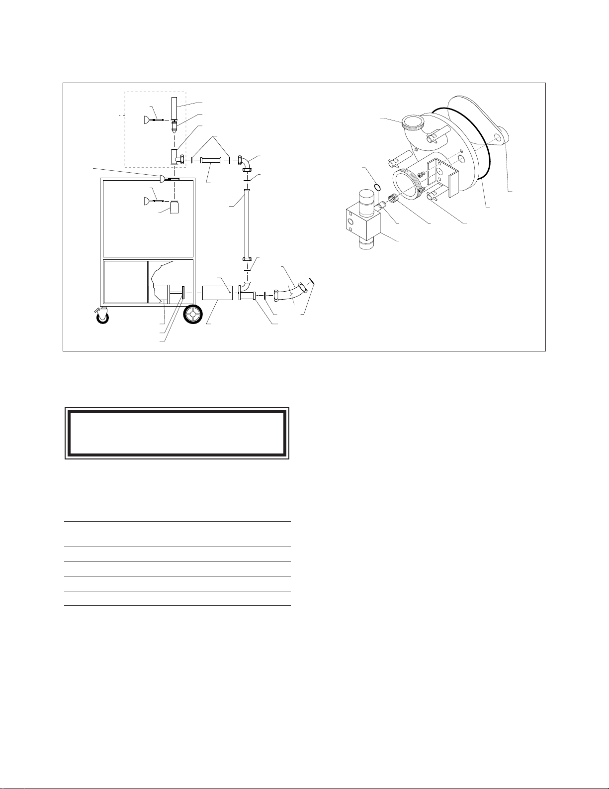
PIPING ASSEMBLIES,
"O" RINGS, GASKETS & SEALS
(see pages 17-18 for actual size illustrations of "O" Rings)
1
A
2
B
3
4
6
5
D
8
9
10
11 3
13
14
15
17
12
3
18
STANDARD
CONFIGURATION
OPTIONAL
STRAINER
CONFIGURATION
15
16
7
D
D
D
I
F
E
G
F
D
C
C
D
H
H
Piston Head
Assembly
(See Page 9)
Page 18

16
PIPING ASSEMBLIES
ITEM ON. PART NO. DESCRIPTION QTY.
1. KE53270 Air Cylinder . . . . . . . . . . . . . . . . . . . . . . . . . . . . . . . . . . . . . . . . . . . .1
2. KE53250 Plunger . . . . . . . . . . . . . . . . . . . . . . . . . . . . . . . . . . . . . . . . . . . . . . . .1
3. KE52087 Sani-clamp, 2" Standard Configuration . . . . . . . . . . . .1
Optional Strainer Configuration . . . . . .3
4. KE01385 Discharge Valve Body . . . . . . . . . . . . . . . . . . . . . . . . . . . . . . . . . . . .1
5. KE54287 Start Switch . . . . . . . . . . . . . . . . . . . . . . . . . . . . . . . . . . . . . . . . . . . .1
6. KE00905 Actuator Assembly . . . . . . . . . . . . . . . . . . . . . . . . . . . . . . . . . . . . . . .9
7. KE01384 Discharge Nozzle . . . . . . . . . . . . . . . . . . . . . . . . . . . . . . . . . . . . . . . .1
8. KE00920 Short Connector Pipe, 2" Standard Configuration . . . . . . . . . . . .1
9 . KE01974 Elbow, 2" . . . . . . . . . . . . . . . . . . . . . . . . . . . . . . . . . . . . . . . . . . . . . .1
10. KE01316-1 Long Connector Pipe, 2" Standard Configuration . . . . . . . . . . . .1
11. KE00920-1 Short Connector Pipe, 2" Optional Strainer Configuration . . . . . .1
12. KE01316-2 Long Connector Pipe, 2" Optional Strainer Configuration . . . . . .1
13. SE50415 Strainer Housing . . . . . . . . . . . . . . . . . . . . . . . . . . . . . . . . . . . . . . . . .1
14. SE50413 Strainer Assembly . . . . . . . . . . . . . . . . . . . . . . . . . . . . . . . . . . . . . . .1
15. SE50414 End Assembly . . . . . . . . . . . . . . . . . . . . . . . . . . . . . . . . . . . . . . . . . .2
16. SE50412 Pin . . . . . . . . . . . . . . . . . . . . . . . . . . . . . . . . . . . . . . . . . . . . . . . . . . .1
17. KE52344 Sani-clamp, 4" . . . . . . . . . . . . . . . . . . . . . . . . . . . . . . . . . . . . . . . . . .1
18. SE50411 Cap . . . . . . . . . . . . . . . . . . . . . . . . . . . . . . . . . . . . . . . . . . . . . . . . . .1
"O" RINGS, GASKETS & SEALS
(see pages 17-18 for actual size illustrations)
ITEM ON. PART NO. DESCRIPTION QTY.
A. FA05002-3 Upper Plunger "O" Ring . . . . . . . . . . . . . . . . . . . . . . . . . . . . . . . . . . .1
B. FA05002-7 Lower Plunger "O" Ring . . . . . . . . . . . . . . . . . . . . . . . . . . . . . . . . . . .1
C. KE52154 Sani-Clamp Gasket, 2" . . . . . . . . . . . . . . . . . . . . . . . . . . . . . . . . . . . .2
D. KE54810-1 Gasket, 2" Standard Configuration . . . . . . . . . . . .4
Optional Strainer Configuration . . . . . .2
E. KE52347 Sani-Clamp Seal, 4" . . . . . . . . . . . . . . . . . . . . . . . . . . . . . . . . . . . . . .1
F. FA00340 Housing "O" Ring . . . . . . . . . . . . . . . . . . . . . . . . . . . . . . . . . . . . . . . .2
G. FA00334 Strainer "O" Ring . . . . . . . . . . . . . . . . . . . . . . . . . . . . . . . . . . . . . . . . .2
H. KE54810-3 Gasket, 3" . . . . . . . . . . . . . . . . . . . . . . . . . . . . . . . . . . . . . . . . . . . . . .2
I. FA05002-26 Product Piston "O" Ring . . . . . . . . . . . . . . . . . . . . . . . . . . . . . . . . . . .1
Page 19

17
"O" RINGS, GASKETS & SEALS
(shown actual size - see page 12 for part locations)
F
FA00340
Housing "O" Ring
CUTAWAY
VIEW
E
KE52347
Sani-Clamp Seal
CUTAWAY
VIEW
C
KE52154
2" Sani-Clamp
Gasket
CUTAWAY
VIEW
CUTAWAY
VIEW
A
FA05002-3
Upper Plunger
"0" Ring
CUTAWAY
VIEW
B
FA05002-7
Lower Plunger
"0" Ring
D
KE54810-1
2" Gasket
CUTAWAY
VIEW
FA00111
Flapper Valve
"O" Ring
Page 20

18
"O" RINGS, GASKETS & SEALS
(shown actual size - see page 12 for part locations)
I
FA05002-5
Product Piston
"O" Ring
FA05002-26
Pneumatic Piston
"O" Ring
CUTAWAY
VIEW
FA0500-21
(not to scale)
Cylinder Seal
H
KE54810-3
3" Gasket
CUTAWAY
VIEW
G
FA00334
Strainer "O" Ring
CUTAWAY
VIEW
CUTAWAY
VIEW
Page 21

19
Air Regulator
AIR PRESSURE
1. Adjust air regulator or line pressure so that air
pressure gauge reads 90 - 100 psi when unit
is running on continuous cycle (stroke
selector switch is set on "constant pumping").
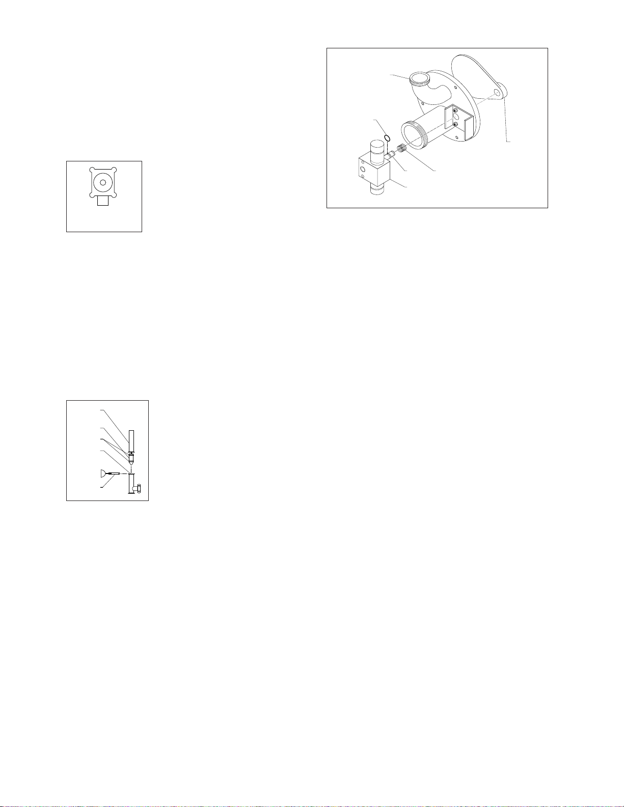
OIL FILLING PROCEDURE
The lubricator puts one
drop of oil into the air lines
for every ten to fifteen
cycles of the product
piston. This ratio should
be checked weekly and
the oil level should be
checked daily.
Lubricator
1. Drip Adjustment-
⇒ Observe the sight bulb on the top of the
oiler. One drop of oil into the lines for every
ten to fifteen cycles of the product piston.
⇒ If adjustment is necessary turn the
adjustment knob next to the sight bulb
clockwise for more oil, counter clockwise for
less oil.
2. Adding Oil-
Use only mineral oil in th oiler.
⇒ Remove air supply from unit.
⇒ Remove oiler cage and bowl. Fill to line
and replace.
AIR FILTER REPLACEMENT
PROCEDURE
The air filter is designed
to separate a small
amount of dirt and water
from the supply air. This
filter is NOT designed to
clean air straight from the
compressor. You must
install a separate filter
and drier in the supply
line to deliver air with a
dew point of less than
65° F.
Filter
1. Check for water accumulation daily. If water is
present, push button at the bottom of bowl
and allow the water to spray out.
NOTE: If the bowl has to be drained regularly
(more than once a week) then the supply air has
not been sufficiently dried.
2. If the air cartridge is dirty then it should be
replaced.
⇒ Remove air connection from unit.
⇒ Remove cage and bowl.
⇒ Turn disk to the left to remove.
⇒ Install new cartridge.
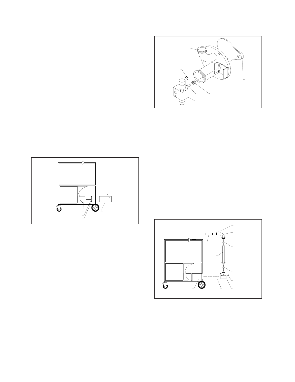
PISTON TIMING
The amount of delay between the time the product
piston reaches the end of a half stroke and the
reversing of direction can be adjusted.
1. Remove the back panel.
2. The two flow controls are located to the left of
the large shuttle valve on the right.
NOTE: The left flow control controls the delay
after the discharge stroke is completed. The right
flow control controls the the delay after the suction
stroke is completed.
3 Loosen locking nut.
4. Set selector switch to continuous and have
someone hold the tripper switch as you adjust
the delay.
5. Retighten the locking nut.
F
B
Deflector
Filter
Element
Baffle
Lever
Bowl/Guard
Assembly
Filler
Cap
Bowl
MAINTENANCE
Oil Sight Bulb
Oil
Adjustor
Oil
Bowl
low Down Button
Pressure Regulator Dial
Pressure
Gauge
Oil
Bowl
Blow
Down
Button
Page 22

ADJUSTMENT & SETTING OF
AIR CUSHION EQUIPPED
PUMP HEADS
SECTION 1 - Adjustment of Valve Paddle Travel
NOTE: When looking at the pump head (paddle
side), left side paddle travel is affected by the
right side air cylinder travel adjustment set screw
and vice versa.
1. Back off 9/16" lock nut on 3/8" dia. set screw
as shown in Figure 1.
2. Adjust set screw until valve paddle is l/8"
away from inside O-ring land edge as shown
in Figure 2.
3. Secure lock nut.
4. Recheck l /8" distance between paddle and
edge.
5. This side is now set. Follow the same
procedure for the other side.
SECTION 2 - Setting of Air Cushion
NOTE A: Again left side paddle cushioning is
affected by the right side air cylinder cushion set
screw (3/16" dia.) and vice versa as shown in
Figure 1.
NOTE B: Turning set screw in increases air
cushion action and vice versa.
CAUTION: Avoid fingers around paddle travel
area, personal injury may result.
1. Support the head assembly securely and
connect the air lines to the rotary actuator air
cylinders. Activate air to start rotary action.
2. Observe air cushion action at the end of each
swing. Optimum cushion action can best be
described as a controlled deceleration of the
paddle at the end of the swing with complete
elimination of rotational momentum in the
shortest time possible. Adjust set screw to
achieve results on both sides.
TROUBLE SHOOTING GUIDE
(reference drawings at back of manual)
1. If there is no air to unit check:
A/ Check that the kettle's Air Quick
Connect is pushed upward to the
"OPEN" position.
Air Quick Connect on Mixer Kettle
B/ Open the back access doors and check that
the 3 way spool valve (item 16 on page 23-
24) is pressed inwards.
2. Made sure the air regulator (large black knob
on back of panel) is turned on for pressure to
enter system. To be sure enough pressure is
in system, check for min. 60 PSI, otherwise
valves might not shift.
3. Recommended operating pressure is 90 to
100 PSI.
4. If the unit seems to be covered in oil or the oil
is dripping out of the mufflers, then turn
lubricator output down. Correct setting is 1
drop every 10-15 strokes.
5. If the pump valve (item 68 on page 23-24 -
the large Airtec valve) does not shift during
operation or is slow in shifting, make sure the
two Legris flow controls are not adjusted right
in. If so, then back them off.
6. If pump cylinder is too slow then adjust large
Aro flow controls (item 12 on page 23-24) to
desired speed.
7. If a leak develops around the air valve 5 bank
manifold (item 16 on page 23-24), tighten the
screws on top of valve and tighten manifold
socket head bolts as these can loosen over
time.
NOTE: Be careful with socket head bolts - do not
tighten too much or clamps will bend on manifold
increasing the leak.
8. If cylinder cycles one way but not back,
check that the limit valves (item 53 on page
23-24) are hitting to make sure contact is
made and signal is sent to either port 19 or 26
of the 5 station valve bank.
9. If cylinder still does not cycle, check or
replace control valve assembly (item 67 on
page 23-24 - top and middle valve) of the 5
station valve bank.
20
Figure 1 Figure 2
1/8" 1/8"
Cushion
Adjustment
Set Screw
Travel
Adjustment
Set Screw
OPEN
Page 23

21
PNEUPAK TROUBLE
SHOOTING GUIDE
1. No air, then turn red sleeve valve on.
2. Make sure that the air regulator (large black
knob on back of panel) is turned on for
pressure to enter system. To be sure enough
pressure is system, check for min. 60 PSI,
otherwise valves might not shift.
3. Recommend 80 to 90 PSI operating pressure.
4. If the unit seems to be covered in oil, or the oil
is dripping out of the mufflers, then turn
lubricator output down.
5. Problems within the complete system can
result if too mush oil is in the air lines and
valves. This could cause the valves not to
shift completely. Recommended oil to be used
as lubricant is a Tellus 32 or ISO32. If oil is
incompatible with Buna-N seals, the seals
may swell and cause the valves and cylinders
to stick.
6. If the pump valve (large Airtec valve) does not
shift during operation or is slow in shifting;
make sure that the two Legris flow controls
are not adjusted right in. If so, then back off.
7. If pump cylinder is too slow then adjust large
Aro flow controls to desired speed.
8. If a leak develops around the air valve 5 bank
manifold; tighten the screws on top of valve
and tighten manifold socket head bolts as
these may loosen over time.
NOTE: Be careful with socket head bolts --- Do
not tighten too much or clamps will bend on
manifold increasing the leak.
9. If pump cylinder cycles one way but not back;
check that the limit valves are actuated to
make sure contact is made and signal is sent
to either port 19 or 26 of the 5 station valve
bank.
10. If cylinder still does not cycle, check or
replace valve 1 & 3 (top and middle valve) of
the 5 station valve bank.
11. If leakage is detected around the selector
switch then check to see if debris is hindering
proper valve actuation. If this is not the case,
then replace the selector switch.
BASIC OPERATION
Single Cycle Operation
Turn the selector switch to the single cycle. It will
then do the following when the start switch is hit:
■ Shifts valve No. 2 second from the top which
turns off valve No. 1 and takes the signal
away from Pt. 24.
■ Single cycle valve is now turned on. It gives a
one shot of air to valve No. 3 which shifts, and
turns on Group A.
■ The pump valve now shifts (Airtec Valve) Pt. 1
and valve No. 4 & 5 shifts Pt. 11 &12. This
actuates Air Cylinder & Rotary Actuator.
■ When the pump reaches its full stroke, it hits
LV1. This shifts valve No. 3 back through Pt.
19 which turns on Group B which shifts the
pump valve (Airtec Valve) at Pt. 2 and shifts
the valves NO. 4 & 5 back through Pt. 22 & 23
which actuates the Air Cylinder and Rotary
Actuator to complete the single cycle.
Constant Pumping Path:
Turn the selector switch to constant pumping
cycle. It will then do the following when the start
switch is hit:
■ Valve No. 2 shifts which in turn shifts valve
No. 1 through Pt. 31. This turns on valve No. 3
through Pt. 24 if LV2 is actuated which turns
on Group A.
■ The pump valve now shifts (Airtec Valve) Pt. 1
and valve No., 4 & 5 shifts Pt. 11 & 12 to
actuate Air Cylinder and Rotary Actuator.
■ When pump reaches the full stroke it hits LV1.
This shifts back Valve No. 3 through Pt. 19
which turns on Group B which shifts pump
valve (Airtec Valve) at Pt. 2 and shifts back
valve No. 4 & 5 through Pt. 22 and Pt. 23
which actuates the Air Cylinder and Rotary
Actuator.
■ When the pump completes the first cycle, LV2
is hit again and turns valve No. 1 back on and
shifts valve No. 3 again through Pt. 24 and
starts another cycle all over again.
■ This will continue until the selector switch is
turned off which turns off the air to valve No. 2
and stops supplying valve No. 1, which will
not turn on valve No. 3 to start another cycle.
Page 24

22
PNEUMATIC SCHEMATIC
Page 25

AIR PACKAGE PARTS DRAWING
23
Page 26

24
AIR PACKAGE PARTS DRAWING LEGEND
Page 27

25
POINT TO
POINT
AIR TUBING
CONNECTIONS
Page 28

26
POINT TO POINT AIR TUBING CONNECTIONS
(continued)
Page 29

27
SPARE PARTS LIST
ITEM ON. DESCRIPTION QTY. QTY.
DOMESTIC OVERSEAS
Consumables
KE54810-3 Gasket, 3", Food Hose 10 50
KE54810-1 Gasket, 2", Piping Assembly 10 50
KE53056 Spring, Pump Head 2 10
KE54167 Food Grade Grease 1 10
FA05002-24 "O" Ring, Flapper Valve 5 20
FA05002-3 "O" Ring, Upper Plunger Seal 10 50
FA05002-2 "O" Ring, Pump Head 10 50
FA05002-7 "O" Ring, Lower Plunger Seal 10 50
FA05002-26 "O" Ring, Product Piston Head 10 50
Spare Parts
FA05002-6 "O" Ring, Rear Seal 1 2
FA05002-1 "O" Ring, Front Seal 1 2
KE01302 Lug Nut 1 2
KE54278 Removable Panel Stop 1 2
KE53266 Spring, Label Dispenser 1 2
KE53014-1 Rotary Actuator --- 1
KE01712 Air Cylinder, Discharge Head --- 1
KE01518 Hose for Clipper --- 1
KE01750 Hose for MFS to Kettle --- 1
KE54286 Air Limit Switch --- 1
KE54295 Air Flow Control --- 1
SE00090 Control Valve Assembly --- 1
SE00091 Pump Valve Assembly --- 1
OPTIONAL STRAINER PARTS
Consumables
FA05002-28 End Assembly 5 10
FA00334 "O" Ring 5 10
KE52347 Gasket, 4", Sani-Clamp 5 10
KE52154 Gasket, 2", Sani-Clamp 5 10
Spare Parts
SE50412 Pin 1 2
KE52087 Sani-Clamp, 2" 1 2
KE52344 Sani-Clamp, 4" 1 2
OPTIONAL THERMO ASSURANCE PACKAGE PARTS
Consumables
FA00008 "O" Ring 5 20
Spare Parts
KE53206 RTD Sensor 1 1
KE53200 Bulb 1 2
KE53203 Clipper Lockout Valve --- 1
 Loading...