

Cleveland Range HA-MKGL-60-CC-T, HA-MKGL-100-CC, HA-MKGL-60-T, HA-MKGL-80, HA-MKGL-80-T User Manual
...Page 1
Operators Manual
Installation, Operation & Service
GAS MIXING KETTLES
HORIZONTAL AGITATOR
MODEL: HA-MKGL-60 HA-MKGL-60-T
HA-MKGL-80 HA-MKGL-80-T
HA-MKGL-100 HA-MKGL-100-T
HA-MKGL-60-CC HA-MKGL-60-CC-T
HA-MKGL-80-CC HA-MKGL-80-CC-T
HA-MKGL-100-CC HA-MKGL-100-CC-T
™
Clev eland
Enodis
1333 East 179th St., Cleveland, Ohio, U.S.A. 44110
Phone: (216) 481-4900 Fax: (216) 481-3782
Visit our web site at www.clevelandrange.com
SE95022 Rev. 5
Page 2
FOR THE USER
WARNING: Improper installation,
adjustment, alteration, service or
maintenance can cause property
damage, injury or death. Read the
installation and operating
instructions thoroughly before
installing or servicing this
equipment.
FOR YOUR SAFETY
DO NOT STORE OR USE GASOLINE
OR ANY OTHER
FLAMMABLE LIQUIDS AND
VAPOURS IN THE VICINITY
OF THIS OR ANY OTHER
APPLIANCE.
IMPORTANT!
ENSURE KETTLE IS AT ROOM TEMPERATURE AND
PRESSURE GAUGE IS SHOWING ZERO OR LESS PRESSURE
PRIOR TO REMOVING ANY FITTINGS.
.
IMPORTANT
The following points are to insure the safe installation and operation of this equipment:
• Insure all gas and electrical supplies match rating plate and electrical stickers.
• Observe all clearance requirements.
• Disconnect the electrical power supply to the appliance before cleaning or servicing unit.
• All service must be performed by a qualified Cleveland Range Technician.
• Do not obstruct the flow of combustion and ventilation air.
The installation and connection must comply with current local codes, or in the absence of local codes, with
CAN/CGA-B149.1 and .2 installation code or with the national fuel gas code, ANSI Z223.1-L988.
Post in a prominent location, instructions to be followed in the event the user smells gas. This information shall
be obtained by consulting your local gas supplier.
The appliance and its individual shut off valve must be disconnected from the gas supply piping system during
any pressure testing of that system at test pressures in excess of 1/2 psig. (3.45 kpa).
The appliance must be isolated from the gas supply piping system by closing its individual manual shut off
valve during any pressure testing of the gas supply piping system at test pressures equal to or less than 1/2
psig. (3.45 kpa).
RETAIN THIS MANUAL FOR YOUR REFERENCE.
Page 3
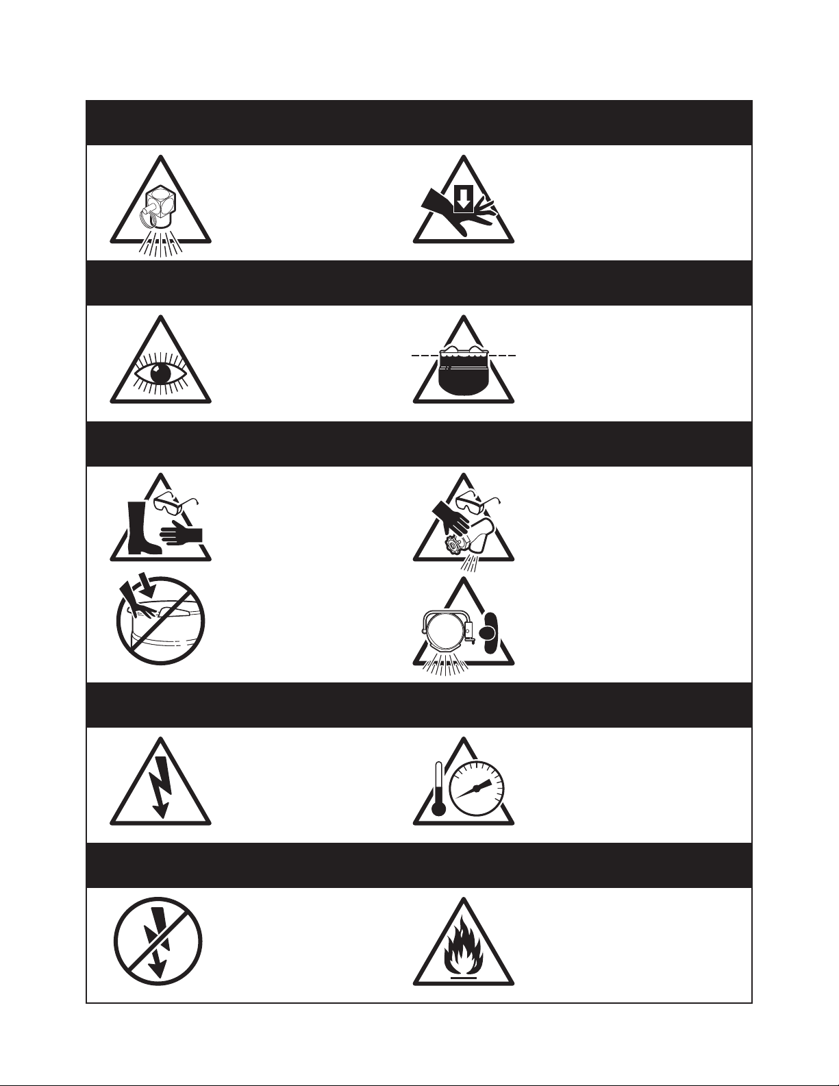
For your safety
DANGER
Keep clear of pressure
relief discharge.
IMPORTANT
Inspect unit daily for
proper operation.
CAUTION
Surfaces may be
extremely hot! Use
protective equipment.
Keep hands away from
moving parts and pinch points.
Do not fill kettle above
recommended level
marked on outside of kettle.
Wear protective equipment
when discharging hot product.
Do not lean on or place
objects on kettle lip.
SERVICING
Shut off power at main
fuse disconnect prior
to servicing.
GAS APPLIANCES
Do not attempt to operate
this appliance during a
power failure.
Stand clear of product
discharge path when
discharging hot product.
Ensure kettle is at room
0
temperature and pressure
gauge is showing zero or less
prior to removing any fittings.
Keep appliance and area free
and clear of combustibles.
Page 4

GENERAL
Installation of the kettle must be accomplished by
qualified installation personnel working to all applicable
local and national codes. Improper installation of
product could cause injury or damage.
This equipment is built to comply with applicable standards
for manufacturers. Included among those approval agencies
are: UL, A.G.A., NSF, ASME/N.Bd., CSA, CGA, ETL, and
others. Many local codes exist, and it is the responsibility of
the owner/installer to comply with these codes.
Observe all clearance requirements to provide proper makeup air flow as well as sufficient clearance for servicing.
Dimensions and clearance specifications are shown on the
specification sheet and in the Clearance Requirements
section. Do not install kick plates or otherwise obstruct the
flow of combustion and ventilation air.
Check rating plate to ensure that kettle has been equipped
to operate with the type of gas available at the installation.
VENTILATION
Gas fired kettles are only to be installed under a
ventilation hood in a room which has provisions for
adequate make up air. Further information can be
obtained by referring to the U.S.A. National Fire
Protection Associations NFPA96 regulations. These
standards have also been adopted by the National
Building Code in Canada.
INSPECTION
Before unpacking visually inspect the unit for evidence
of damage during shipping. If damage is noticed, do
not unpack the unit, follow shipping damage
instructions.
SHIPPING DAMAGE
INSTRUCTIONS
If shipping damage to the unit is discovered or
suspected, observe the following guidelines in
preparing a shipping damage claim.
1. Write down a description of the damage or the
reason for suspecting damage as soon as it is
discovered. This will help in filling out the claim
forms later.
2. As soon as damage is discovered or suspected,
notify the carrier that delivered the shipment.
3. Arrange for the carrier's representative to examine
the damage.
4. Fill out all carrier claims forms and have the
examining carrier sign and date each form.
CLEARANCE REQUIREMENTS
This unit must be installed in accordance with the
clearances shown on the rating label which is adhered
to the unit.
FOR YOUR SAFETY. Keep the appliance area free and
clear of combustible materials.
KETTLE
1. When removing the kettle from the platform, handle
with care to prevent scratching or any other
damage. It is imperative that the kettle be level
before bolting to the floor. This will prevent any
twist or out of roundness to the kettle and will stop
deflection of the agitator. Make sure the kettle is
securely bolted to the floor and follow the
procedure listed below:
⇒ Raise the flange on the leg under the motor so
that it sets freely (stationary kettles only).
⇒ Position the kettle in its permanent location,
check clearances and level the kettle by turning
the adjustable feet.
⇒ Lower the flange or flanges under the motor
channel. Over adjustment, whether up or down,
could cause misalignment and cause damage to
the agitator drive shaft and hub (stationary kettles
only).
2. Next you must check the alignment of the drive
shaft for a uniform clearance between the hub and
the shaft. In order to check for clearance you must
remove the seal cover plate and pull the seal back.
you can check the distance for clearance by using
a wire feeler gauge.
3. If adjustment is required for side direction, loosen
the motor bolts, center the shaft and retighten.
If vertical alignment is needed, loosen the motor
bolts and add a shim to raise or remove a shim to
lower. Retighten bolts. When this is complete,
check to see if the agitator shaft coupling slides
freely for easy removal of the agitator.
4. Once positioned and leveled, permanently secure
the kettle’s flanged feet to the floor using 1/2 x 2 I/2
inch lag bolts and floor anchors (supplied by the
installer). Two bolts per leg are required to secure
each of the flanged feet.
INSTALLATION
Page 5

GAS
It is recommended that a sediment trap (drip leg) be
installed in the gas supply line. If the gas pressure
exceeds 14” water column, a pressure regulator must
be installed, to provide a maximum of 14” water column
gas pressure to the gas control valve.
Connect the gas supply piping to the input side of the
gas control valve. Location and pressure data are
shown on the specification sheet.
Installation must be in accordance with local codes
and/or the National Fuel Gas Code ANSI Z223.1-1988
(USA) or the Installation Codes for Gas Burning
Appliances and Equipment CANI B149.1 and B149.2
(Canada). Use a gas pipe joint compound which is
resistant to L.P. gas. Test all pipe joints for leaks with
soap and water solution. Ensure that the gas pressure
regulator is set for the manifold pressure indicated on
the gas rating plate.
The appliance and its individual shut-off valve must be
disconnected from the gas supply piping system during
any pressure testing of that system at test pressures in
excess of 1/2 psi (3.45 kPa). The appliance must be
isolated from the gas supply piping system by closing
its individual manual shut-off valve during any pressure
testing of the gas supply piping system at test
pressures equal to or less than 1/2 psi (3.45 kPa).
ELECTRICAL
Electrical installation must be in accordance with local
codes and/or the National Electric Code ANSI/NFPA 701990 (USA) or the Canadian Electrical Code CSA
Standard C22.1 (Canada). The kettle must be
electrically grounded by the installer.
A separate fused disconnect switch must be supplied
and installed in the high voltage electrical supply line.
The wire gauge size and electric supply must match the
power requirements specified on the kettle’s rating
plate. The waterproof conduit enclosed permanent
copper wiring must be adequate to carry the required
current at the rated voltage. Refer to the specification
sheet or rating label for electrical specifications and
location of electrical connections.
Remove the screws securing the component cover
(located to the left rear side of kettle), and remove the
cover. A wiring diagram is affixed to the inside of the
cover. Feed conduit enclosed permanent copper wiring
through the cut-out in the bottom of the console and
fasten to the terminal block. Fasten the ground wire to
the ground lugs connected to the frame, beside the
terminal block. Replace the console cover and secure it
with the screws.
WATER
The sealed jacket of the gas-fired kettle is precharged
with the correct amount of a water-based formula, and
therefore, no water connection is required to the kettle
jacket.
CLEANING
After installation the kettle must be thoroughly cleaned
and sanitized prior to cooking.
WARRANTY
Our Company supports a worldwide network of
Maintenance and Repair Centres. Contact your nearest
Maintenance and Repair Centre for replacement parts,
service, or information regarding the proper
maintenance and repair of your cooking equipment
In order to preserve the various agency safety
certification (UL, A.G.A., NSF, ASME/Ntl. Bd., etc.), only
factory-supplied replacement parts should be used. The
use of other than factory supplied replacement parts will
void warranty.
Page 6
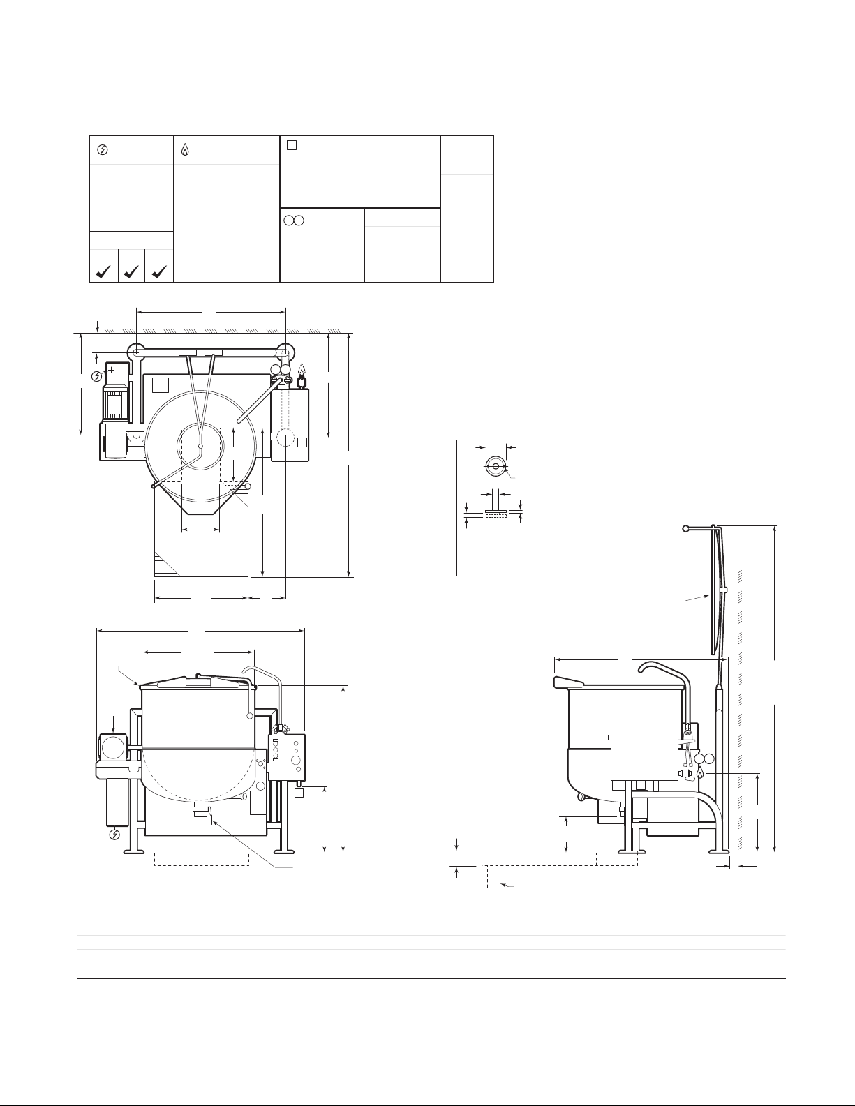
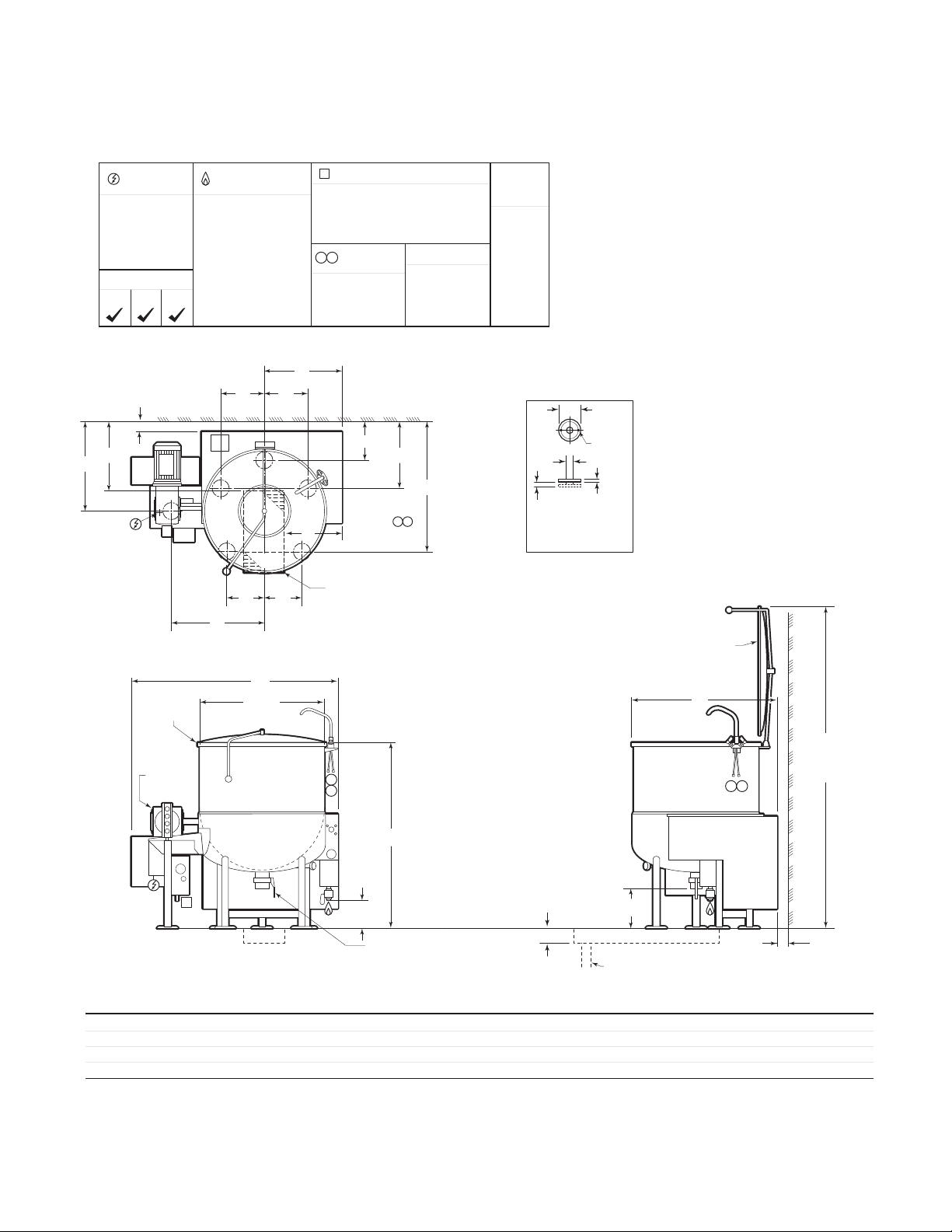
SPECIFICATION DRAWING STATIONARY MODELS
A
ELECTRICAL
SUPPLY
VOLTS: 208/240
PHASE: 3
AMPS: 15
FREQ: 60 HZ
APPROVALS
AGA CGA NSF
GAS SUPPLY
(PIPING 3/4" NPT)
TYPE: NAT or LP
BTU PER CU. FT.:
1000 (NAT), 2500 (LP)
SUPPLY PRESSURE:
4" to 14" W.C.
BTU RATINGS:
190,000 per hour
G
AIR SUPPLY (PIPING 1/2" NPT)
PRESSURE:
90 - 100 PSI
(only required for optional 3" dia.
piston draw-off valve)
HOT & COLD
H C
WATER
1/2" NPT CONNECTION
40-60 PSI PRESSURE
CLEARANCE
RIGHT: 3", LEFT: 3"
REAR: 5"
(ALLOW 12" SPACE
MINIMUM ON LEFT
SIDE FOR SERVICE)
APPROX.
SHIPPING
WEIGHTS
60 GAL -
1010 LBS.
458 KG.
80 GAL -
1120 LBS.
508 KG.
100 GAL -
1325 LBS.
601 KG.
F
7 3/4"
RIM BAR
3 HP
ELECTRIC
MOTOR
WALL
12"
RECOMMENDED
FLOOR DRAIN
28" L
C
A I.D.
16"
H C
M
H
A
J
5 1/2"
2"
(MAX. ADJUSTMENT)
1"
5/8"Ø,
2 HOLES
ON
4" B.C.D.
3/8"
SOLID
FOOT DETAIL
SPRING ASSIST
COVER (FULLY
OPEN AT 90 )
WALL
D
E
(COVER
FULLY
OPEN)
B
CH
A
S
3" DIA. BUTTERFLY VALVE
RECOMMENDED FLOOR
SLOPE 1 INCH PER 4 FEET
6" RECOMMENDED
FLOOR DRAIN
PIPE DRAIN RECOMMENDED
MINIMUM VALVE SIZE PLUS 1"
13"
A
DIMENSIONS
MODEL
HA-MKGL-60-TCC
HA-MKGL-80-TCC
HA-MKGL-100-TCC
NOTES: CLEVELAND RANGE EQUIPMENT IS BUILT TO COMPLY WITH APPLICABLE STANDARDS FOR MANUFACTURERS. INCLUDED AMONG THOSE APPROVAL AGENCIES ARE: UL, A.G.A., NSF, ASME/N.BD., CSA, CGA, ETL, AND OTHERS.
INSTALLATIONS OF BACK FLOW PREVENTERS, VACUUM BREAKERS AND OTHER SPECIFIC CODE REQUIREMENTS ARE THE RESPONSIBILITY OF THE OWNER AND INSTALLER.
ALL VERTICAL DIMENSIONS SHOWN ARE MINIMUM. FEET ARE ADJUSTABLE TO +1" MAXIMUM.
MANUFACTURER MUST BE NOTIFIED IF UNIT WILL BE OPERATING ABOVE 2000' ALTITUDE.
CONSULT FACTORY FOR MANUFACTURED GAS.
Cleveland Range reserves right of design improvement or modification, as warranted.
A
29 1/2"
33"
35 1/2"
B
48 1/4"
51 3/4"
54 1/4"
C
61 5/8"
65 3/8"
68 3/8"
D
46 3/4"
52"
55"
93"
98"
104"
E
F
27 3/4"
30 3/4"
32 3/4"
G
42"
45 11/16"
48 3/16"
H
30 5/8"
33 5/8"
35 5/8"
J
78"
84"
95 5/8"
L
10 3/8"
11 7/16"
11 5/8"
53"
57"
66"
M
S
19 1/4"
20 3/4"
22"
T
5" MIN
CLEARANCE
T
24 1/2"
26 3/16"
27 5/8"
Page 7
SPECIFICATION DRAWING TILTING MODELS
A
ELECTRICAL
SUPPLY
VOLTS: 208/240
PHASE: 3
AMPS: 15
FREQ: 60 HZ
APPROVALS
AGA CGA NSF
K
3" REF.
GAS SUPPLY
(PIPING 3/4" NPT)
TYPE: NAT or LP
BTU PER CU. FT.:
1000 (NAT), 2500 (LP)
SUPPLY PRESSURE:
4" to 14" W.C.
BTU RATINGS:
190,000 per hour
M M
WALL
PNP
C
L
AIR SUPPLY (PIPING 1/2" NPT)
PRESSURE:
90 - 100 PSI
(only required for optional 3" dia.
piston draw-off valve)
HOT & COLD
H C
WATER
1/2" NPT CONNECTION
40-60 PSI PRESSURE
L
10 3/8
F
12" X 24"
RECOMMENDED
FLOOR DRAIN
CLEARANCE
RIGHT: 3", LEFT: 3"
REAR: 3"
(ALLOW 12" SPACE
MINIMUM ON LEFT
SIDE FOR SERVICE)
18 3/8Q
G
H C
APPROX.
SHIPPING
WEIGHTS
60 GAL -
940 LBS.
428 KG.
80 GAL -
1030 LBS.
469 KG.
100 GAL -
1110 LBS.
505 KG.
5 1/2"
2"
(MAX. ADJUSTMENT)
1"
SOLID
FOOT DETAIL
5/8"Ø,
2 HOLES
ON
4" B.C.D.
3/8"
SPRING ASSIST
COVER (FULLY
OPEN AT 90 )
RIM BAR
3 HP
ELECTRIC
MOTOR
C
A I.D.
D
H
C
H C
WALL
B
RECOMMENDED FLOOR
SLOPE 1 INCH PER 4 FEET
A
8 3/4"
3" DIA. BUTTERFLY VALVE
6" RECOMMENDED
13"
FLOOR DRAIN
PIPE DRAIN RECOMMENDED
MINIMUM VALVE SIZE PLUS 1"
CLEARANCE
DIMENSIONS
MODEL
HA-MKGL-60-CC
HA-MKGL-80-CC
HA-MKGL-100-CC
NOTES: CLEVELAND RANGE EQUIPMENT IS BUILT TO COMPLY WITH APPLICABLE STANDARDS FOR MANUFACTURERS. INCLUDED AMONG THOSE APPROVAL AGENCIES ARE: UL, A.G.A., NSF, ASME/N.BD., CSA, CGA, ETL, AND OTHERS.
INSTALLATIONS OF BACK FLOW PREVENTERS, VACUUM BREAKERS AND OTHER SPECIFIC CODE REQUIREMENTS ARE THE RESPONSIBILITY OF THE OWNER AND INSTALLER.
ALL VERTICAL DIMENSIONS SHOWN ARE MINIMUM. FEET ARE ADJUSTABLE TO +1" MAXIMUM.
MANUFACTURER MUST BE NOTIFIED IF UNIT WILL BE OPERATING ABOVE 2000' ALTITUDE.
CONSULT FACTORY FOR MANUFACTURED GAS.
A
29 1/2"
33"
35 1/2"
B
48 1/4"
51 3/4"
54 1/4"
C
50"
58"
60 1/2"
D
36 1/2"
39"
40 3/4"
83"
90"
96"
E
F
13 1/8"
14 7/8"
16 1/8"
G
34 5/8"
35 15/16"
37 1/8"
K
23 7/8"
24 5/8"
25 1/4"
L
19 1/8"
20 7/8"
22 1/8"
M
10 3/32"
11 17/32"
12 3/4"
N
24"
26"
27 1/4"
P
9 3/4"
9 3/4"
11"
E
(COVER
FULLY
OPEN)
3" MIN
Q
17 7/8"
18 5/8"
19 1/4"
Cleveland Range reserves right of design improvement or modification, as warranted.
Page 8
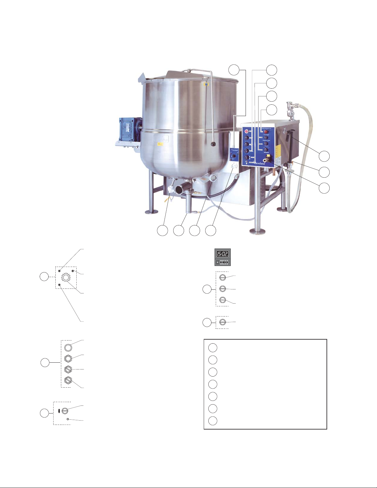
OPERATING INSTRUCTIONS
C
E
D
21 3
A
B
C
NOTE:
Location of
switches may
vary dependant
on customers
specific options
D
E
7
5
6
4
Red Low Water Indicator Light
When lit, in the upright position, indicates kettle gas
burner has cut out and unit requires more water.
Occasional pulsing of this light is normal.
A
B
C
Green Heat Indicator Light
When lit, indicates gas burner is on; cycles on-off with
solid state controls.
Solid State Temperature Control Knob /
On-Off Toggle Switch
Controls electrical power to kettle. and allows operator to
select kettle heat increments from minimum, 1-10.
A setting of 7 or higher will boil water
Amber Ignition Failure Indicator Light
Indicates failure of heating system to ignite
(Used prior to July 2004)
Agitator Stop Button
Stops agitator in case of emergency
Agitator Start Switch
Starts agitator. Agitator power control switch must be ON
Agitator Power Switch
Allows power to agitator. When not in use, turn control
power OFF
Agitator Speed Control Switch
Turn clockwise until desired speed is reached
Power tilt control switch
Tilts kettle for pouring; some kettles have manual hand tilt
Reset circuit breaker
Protects power tilt system from overload. Push to reset
D
E
1
2
3
4
5
6
7
Water Meter Digital Counter (not shown)
Location may vary dependant on customer's specific
options
0123
Fill Interrupt Switch
Interrupts water fill cycle
Potable Fill Water Switch
Selects hot or cold water
Fill Cycle Switch
Start/continue cycle switch
Product Discharge Valve Switch
Toggle momentary switch to desired valve opening
Temperature Sensor
Senses temperature of product
Automatic Dump Valve
Empties kettle of either food product or wash water
Sight Glass
For checking water level of kettle jacket
Vacuum /Pressure Gauge
Indicates steam pressure inside steam jacket in PSI, as
well as vacuum in inches of mercury
Gas Shut-Off Valve
Air Quick Connect
Push yellow tab down to release air pressure before
disconnecting air hose
Kettle Filler Nozzle
Page 9

General
WARNING:
Do not attempt to operate this appliance
during a power failure. Keep appliance and area free and
clear of combustibles.
Before turning kettle on, ensure that following
conditions exist:
• If you are cooking an egg or milk product, do not
pre-heat kettle.
• The vacuum/pressure gauge needle is in green
zone; if it is not and is in "vent air" zone, call your
service agent to repair leak.
• The electrical service to kettle is turned on
NOTE:
The kettle should be sanitized prior to the daily
production run - see CLEANING INSTRUCTIONS .
Mixing ("AGITATOR ")
WARNING:
•
Never add product to kettle while agitator is running.
•
Do not put hands in kettle.
•
Watch for loose clothing near agitator.
1. Turn "SPEED CONTROL" to "0".
2. Switch agitator to "ON".
3. Push agitator "START" to initiate mixing.
4. Turn "SPEED CONTROL" to desired mixing speed.
5. To stop mixing action, push agitator stop button.
NOTE:
Mixing speed depends on the product
consistency. The faster the mixing speed the more
damage may be done to fragile product.
Heating (General Notes)
• The green light cycles on and off, indicating that
burners are cycling to maintain set temperature.
• The red "low water" light should not be lit during
operation. This light indicates that water level is
critically low and that gas burners have
automatically shut off. Before further use, refer to
RESERVOIR FILL INSTRUCTIONS for adding
distilled water.
• Occasional flashing of the red "low water" light is ok
while kettle is heating.
Manual Heating
1. Switch "POWER" to "ON".
2. Turn temperature control knob to desired setting.
3. Switch "CONTROLLER" to "BYPASS".
4. After closing discharge valve, place product in kettle.
Automatic Heating
1. Switch "CONTROLLER" to "ACTIVE".
2. Turn temperature control knob to "10".
3. Continually push function key " " until "OFF" is
displayed.
4. Push and hold key " " or " " until desired
temperature is set.
5.
To Start:
push function key
" " until "CtrL" is displayed.
6. Push down key " ".
7.
To Stop:
push function key
" " until "OFF" is displayed.
8. Push down key " ".
9. After closing discharge valve, place product in kettle.
Emptying the Kettle
1. To open automatic dump valve:
• Turn PRODUCT DISCHARGE VALVE switch
clockwise to JOG TO OPEN. Release switch to the
HOLD position when desired valve opening is
achieved.
• To close valve, turn switch counterclockwise to
CLOSED position.
2. To avoid splashing, slowly empty kettle contents into
an appropriate container by partially opening dump
valve.
NOTE:
When pumping with a Metering Filling Station the
speed of the agitator arm must be sufficient to suspend
the heavier items in the mix in order to achieve an even
distribution in your packaged items.
3.
Immediately clean kettle as outlined in CLEANING
INSTRUCTIONS on page.
Water Meter
1. Switch "POTABLE FILL WATER" to "HOT" or "COLD".
2. Set required volume by first pushing the " " key
until the digit you want to change is flashing in the
lower display. Then use the " " key to change the
value of the selected digit.
When all digits are set, press the "ENT" key.
3. Locate delivery spout over kettle.
4. Turn switch to "RESET". Delivery will start at "0" and
stop at preset volume.
5. To stop delivery at any time, turn "FILL INTERRUPT"
switch to " ● ".
6. To complete delivery after interrupting, turn switch
"FILL CYCLE" to "CONTINUE".
Page 10
CARE AND CLEANING
Cooking equipment must be cleaned regularly to
maintain its fast, efficient cooking performance and
to ensure its continued safe, reliable operation. The
best time to clean is shortly after each use (allow
unit to cool to a safe temperature).
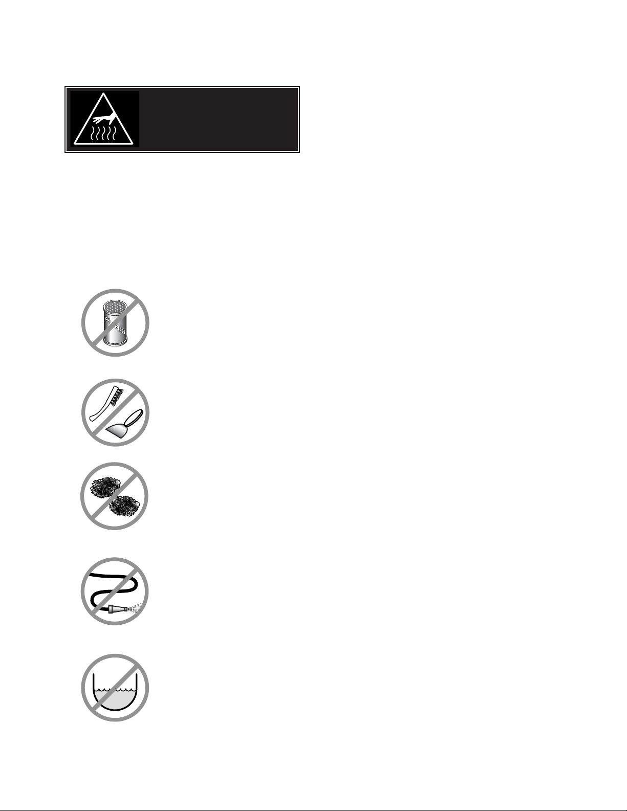
WARNINGS
➩ Do not use detergents or
cleansers that are chloride
based or contain quaternary
salt.
➩ Do not use a metal bristle
brush or scraper.
➩ Steel wool should never be
used for cleaning the stainless
steel.
➩ Unit should never be cleaned
with a high pressure spray
hose.
➩
Do not leave water sitting in unit
when not in use.
Stagnant
Water
High Pressure
Spray Hose
Chloride Cleaners
Steel Pads
Wire Brush &
CLEANING INSTRUCTIONS
CAUTION
SURFACES MAY
BE EXTREMELY HOT!
CLEANING INSTRUCTIONS
1. Turn unit off.
2. Remove drain screen (if applicable). Thoroughly
wash and rinse the screen either in a sink or a
dishwasher.
3. Prepare a warm water and mild detergent solution in
the unit.
4. Remove food soil using a nylon brush.
5. Loosen food which is stuck by allowing it to soak at
a low temperature setting.
6. Drain unit.
7. Rinse interior thoroughly.
8. If the unit is equipped with a Tangent Draw-Off
Valve, clean as follows:
a) Disassemble the draw-off valve first by turning
the valve knob counter-clockwise, then turning
the large hex nut counter-clockwise until the
valve stem is free of the valve body.
b) In a sink, wash and rinse the inside of the valve
body using a nylon brush.
c)
Use a nylon brush to clean tangent draw-off tube.
d) Rinse with fresh water.
e) Reassemble the draw-off valve by reversing the
procedure for disassembly. The valve's hex nut
should be hand tight only.
9. If the unit is equipped with a Butterfly Valve, clean
as follows:
a) Place valve in open position.
b) Wash using a warm water and mild detergent
solution.
c) Remove food deposits using a nylon brush.
d) Rinse with fresh water.
e) Leave valve open when unit is not in use.
10 . Using mild soapy water and a damp sponge, wash
the exterior, rinse, and dry.
NOTES
➩ For more difficult cleaning applications one of the
following can be used: alcohol, baking soda, vinegar,
or a solution of ammonia in water.
➩ Leave the cover off when the kettle is not in use.
➩ For more detailed instructions refer to the Nafem
Stainless Steel Equipment Care and Cleaning manual
(supplied with unit).
Page 11

STAINLESS STEEL EQUIPMENT CARE AND CLEANING
(Suppied courtesy of Nafem. For more information visit their web site at www.nafem.org)
Contrary to popular belief, stainless steels ARE susceptible to rusting.
Corrosion on metals is everywhere. It is recognized quickly on iron and
steel as unsightly yellow/orange rust. Such metals are called “active”
because they actively corrode in a natural environment when their atoms
combine with oxygen to form rust.
Stainless steels are passive metals because they contain other metals, like
chromium, nickel and manganese that stabilize the atoms. 400 series
stainless steels are called ferritic, contain chromium, and are magnetic;
300 series stainless steels are called austenitic, contain chromium and
nickel; and 200 series stainless, also austenitic, contains manganese,
nitrogen and carbon. Austenitic types of stainless are not magnetic, and
generally provide greater resistance to corrosion than ferritic types.
With 12-30 percent chromium, an invisible passive film covers the steel’s
surface acting as a shield against corrosion. As long as the film is intact
and not broken or contaminated, the metal is passive and stain-less. If the
passive film of stainless steel has been broken, equipment starts to
corrode. At its end, it rusts.
Enemies of Stainless Steel
There are three basic things which can break down stainless steel’s
passivity layer and allow corrosion to occur.
1. Mechanical abrasion
2. Deposits and water
3. Chlorides
Mechanical abrasion means those things that will scratch a steel surface.
Steel pads, wire brushes and scrapers are prime examples.
Water comes out of the faucet in varying degrees of hardness. Depending
on what part of the country you live in, you may have hard or soft water.
Hard water may leave spots, and when heated leave deposits behind that
if left to sit, will break down the passive layer and rust stainless steel. Other
deposits from food preparation and service must be properly removed.
Chlorides are found nearly everywhere. They are in water, food and table
salt. One of the worst chloride perpetrators can come from household and
industrial cleaners.
So what does all this mean? Don’t Despair!
Here are a few steps that can help prevent stainless steel rust.
1.
Use the proper tools.
When cleaning stainless steel products, use non-abrasive tools. Soft
cloths and plastic scouring pads will not harm steel’s passive layer.
Stainless steel pads also can be used but the scrubbing motion must
be in the direction of the manufacturers’ polishing marks.
2.
Clean with the polish lines.
Some stainless steel comes with visible polishing lines or “grain.”
When visible lines are present, always scrub in a motion parallel to the
lines. When the grain cannot be seen, play it safe and use a soft cloth
or plastic scouring pad.
3.
Use alkaline, alkaline chlorinated or non-chloride containing cleaners.
While many traditional cleaners are loaded with chlorides, the industry
is providing an ever-increasing choice of non-chloride cleaners. If you
are not sure of chloride content in the cleaner used, contact your cleaner
supplier. If your present cleaner contains chlorides, ask your supplier if
they have an alternative. Avoid cleaners containing quaternary salts; it
also can attack stainless steel and cause pitting and rusting.
4.
Treat your water.
Though this is not always practical, softening hard water can do much
to reduce deposits. There are certain filters that can be installed to
remove distasteful and corrosive elements. To insure proper water
treatment, call a treatment specialist.
5.
Keep your food equipment clean.
Use alkaline, alkaline chlorinated or non-chloride cleaners at
recommended strength. Clean frequently to avoid build-up of hard,
stubborn stains. If you boil water in stainless steel equipment,
remember the single most likely cause of damage is chlorides in the
water. Heating cleaners that contain chlorides have a similar effect.
6.
Rinse, rinse, rinse.
If chlorinated cleaners are used, rinse and wipe equipment and
supplies dry immediately. The sooner you wipe off standing water,
especially when it contains cleaning agents, the better. After wiping
equipment down, allow it to air dry; oxygen helps maintain the
stainless steel’s passivity film.
7.
Never use hydrochloric acid (muriatic acid) on stainless steel.
8.
Regularly restore/passivate stainless steel.
Recommended cleaners for specific situations
Job Cleaning Agent Comments
Routine cleaning Soap, ammonia, Apply with cloth or sponge
detergent, Medallion
Fingerprints & smears Arcal 20, Lac-O-Nu Provides barrier film
Ecoshine
Stubborn stains & Cameo, Talc, Zud, Rub in direction of polish lines
discoloration First Impression
Grease & fatty acids, Easy-off, De-Grease Excellent removal on all finishes
blood, burnt-on-foods It Oven Aid
Grease & oil Any good Apply with sponge or cloth
commercial detergent
Restoration/Passivation Benefit, Super Sheen
Review
1. Stainless steels rust when passivity (film-shield) breaks down as a
result of scrapes, scratches, deposits and chlorides.
2. Stainless steel rust starts with pits and cracks.
3. Use the proper tools. Do not use steel pads, wire brushes or scrapers
to clean stainless steel.
4. Use non-chlorinated cleaners at recommended concentrations. Use
only chloride- free cleaners.
5. Soften your water. Use filters and softeners whenever possible.
6. Wipe off cleaning agent(s) and standing water as soon as possible.
Prolonged contact causes eventual problems.
To learn more about chloride-stress corrosion and how to prevent it,
contact the equipment manufacturer or cleaning materials supplier.
Developed by Packer Engineering, Naperville, Ill., an independent testing
laboratory.
Page 12
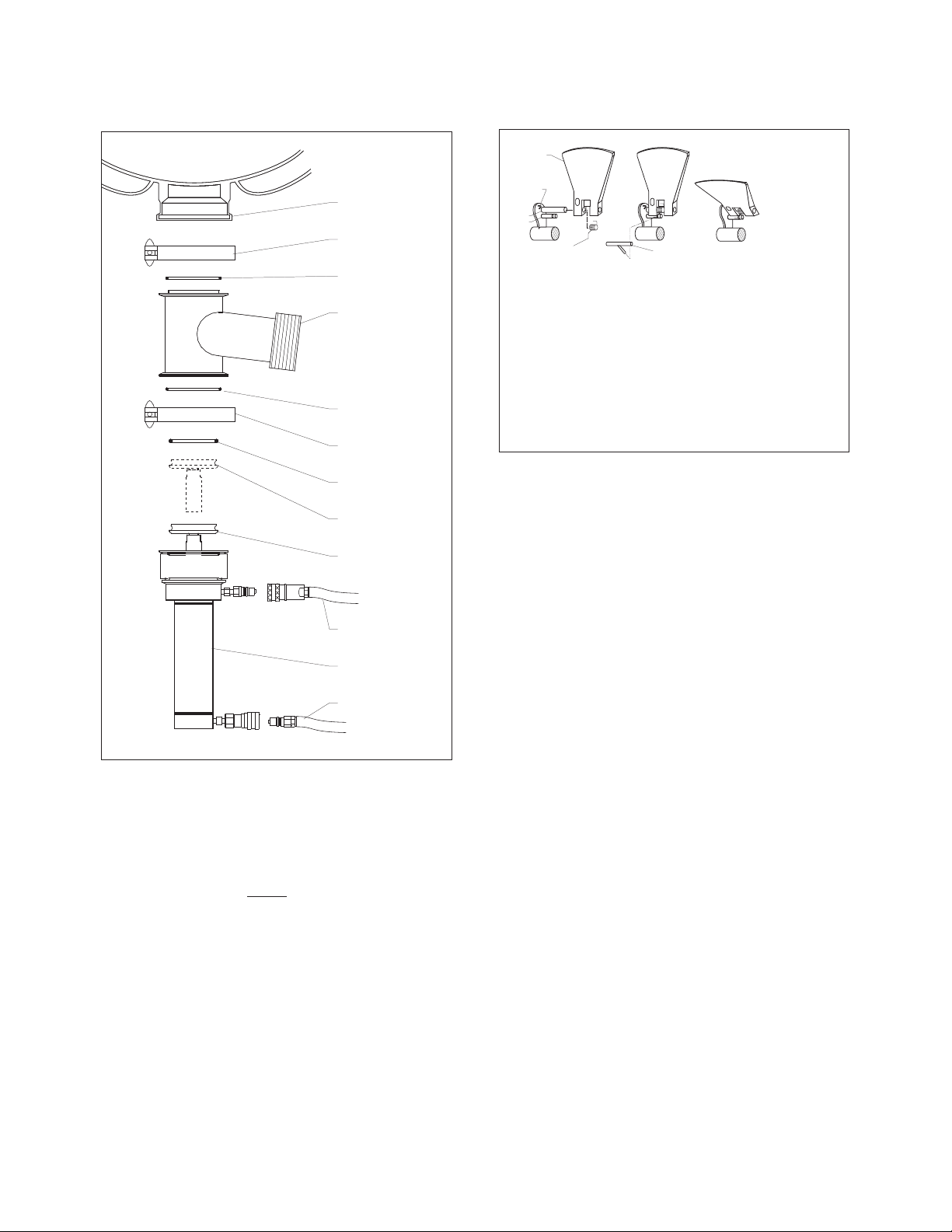
PRODUCT VALVE
Daily
- clean product valve as follows:
1.
Open product valve.
2.
Disconnect air hoses.
3.
Remove air cylinder.
4.
Remove valve tee.
5.
Remove all O-rings.
6.
Clean air cylinder, do not submerge in water. Wipe
clean and sanitize.
7.
Clean and sanitize tee and O-rings.
8.
Grease and reinstall O-rings.
9.
Reinstall tee to kettle outlet.
10.
Reinstall air cylinder to bottom of tee.
11.
Reconnect air hoses.
12.
Close valve and check for alignment.
SCRAPER BLADES
To remove and clean scraper blades:
1. Remove scraper blades using the tool to release
the spring from the retaining pin and sliding the
blade off the shaft.
2. Place parts in a pan of warm water to soak.
3. Clean in a sink, using a warm water and mild
detergent solution.
4. Rinse with fresh water.
5. Allow to dry thoroughly on a flat, clean surface.
AIR HOSE
AIR
CYLINDER
AIR HOSE
OPEN
POSITION
CLOSED
POSTITION
0-RING
CLAMP
0-RING
VALVE
TEE
0-RING
CLAMP
KETTLE
OUTLET
KETTLE
Scraper
blade
Back stop
Pin A
Pin B
Spring
To Remove Scraper Blade
1. Insert tool that is provided as shown in Fig. 2.
2. Pull up on spring arm until arm clears groove in Pin B.
3. Spring is now disengaged, gently release spring to remove
scraper blade.
To Install Scraper Blade
1. Slide scraper blade and spring onto Pin A as shown in Fig. 1.
2. Hook spring arm and pull up.
3. Using tool, engage spring arm into groove on Pin B.
Scraper blade is now in place.
Tool
Fig. 2 Fig. 3Fig. 1
Page 13
AGITATOR
To remove and clean agitator (two-person
job):
Removing Agitator
1. Remove scraper blades.
2. Rotate agitator until pull pin is on top side.
3. Turn power OFF.
4. Pull pin out.
5. Slide coupling toward kettle wall, and carefully lift
agitator pulling back to lift out.
6. Clean in a sink, using a warm water and mild
detergent solution.
7. Rinse with fresh water.
AGITATOR BUSHING
With agitator out, remove bushing by:
1. Remove bushing
by turning 1/4 turn
and pulling away
from the kettle wall.
2. Clean, rinse and
sanitize bushing and bushing mounting area.
3. Lubricate metal surfaces with food safe grease.
4. Install bushing by locating retaining pin and sliding
bushing on.
5. Rotate to lock into position.
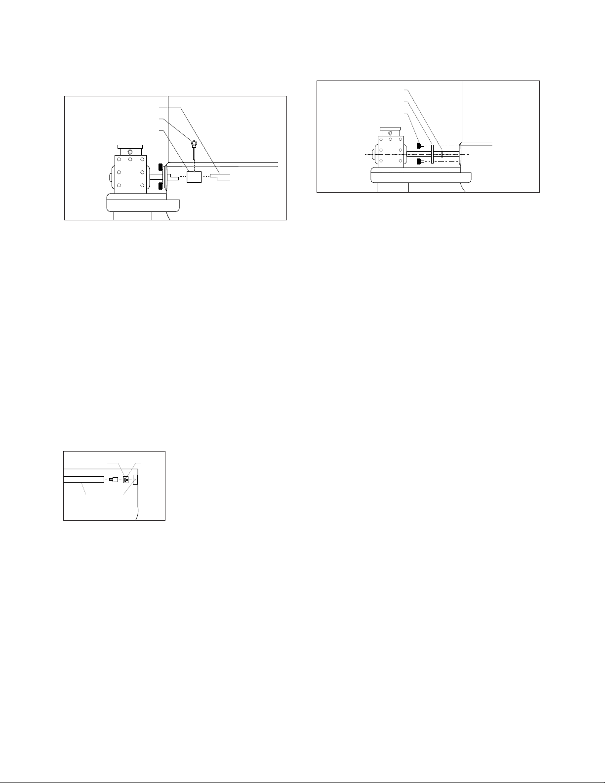
QUAD RING
To clean agitator quad ring:
Cleaning Quad Ring
1. Remove retaining knobs.
2. Slide shaft seal retainer plate and quad ring away
from kettle body.
3. Clean quad ring, shaft, and seal retainer plate with
clean cloth.
4. Rinse with fresh.
5. Apply light coat of food safe grease to both sides
of the quad ring.
6. Slide quad ring back into original position, making
sure it does not twist.
7. Slide retainer plate back toward kettle, replacing
retaining knobs.
8. Tighten with hand pressure only.
Agitator shaft
Pin
Coupling
Quad ring
Seal retainer plate
Retaining knobs
Slot
Bushing
Retaining
pin
Agitator
Shaft
Page 14
Agitator
Shaft
1 2 3
4 5 76
SCRAPER BLADES
ITEM NO. PART NO. DESCRIPTION QTY.
1. KE54602 SCRAPER BLADE . . . . . . . . . . . . . . .7
2. KE54608 SPRING . . . . . . . . . . . . . . . . . . . . . . .7
3. KE01976 SPRING REMOVAL TOOL . . . . . . . . 1
1
2
3
AGITATOR SEAL ASSEMBLY
ITEM
NO. PART NO. DESCRIPTION QTY.
1. KE01911 RETAINING KNOBS . . . . . 3
2. KE54592 SEAL RETAINER PLATE . . 1
3. FA05002-8 "O" RING . . . . . . . . . . . . . . 1
4. KE54594 PIN . . . . . . . . . . . . . . . . . . 1
5. KE54583 COUPLING . . . . . . . . . . . . 1
6. KE54593 IDLER PIN . . . . . . . . . . . . 1
7. KE54590 BUSHING . . . . . . . . . . . . . 1
OPERATING CONTROLS
ITEM NO. PART NO. DESCRIPTION QTY.
1. KE54531 AGITATOR STOP . . . . . . . . . . . . . . . . . . . . . . 1
2. KE54530 AGITATOR START . . . . . . . . . . . . . . . . . . . . . 1
3. KE54529 POWER ON/OFF SWITCH . . . . . . . . . . . . . . . 1
4. KE54532 SPEED CONTROL . . . . . . . . . . . . . . . . . . . . . 1
2
1
3
4
SERVICE PARTS
Page 15
PRESSURE RELIEF ASSEMBLY
5
4 3 1
2
ITEM NO. PART NO. DESCRIPTION QTY.
1. FA05049 MALE CONNECTOR, 1/2" PIPE - 1/4" TUBE . . . . . . . . . . . . . . . . . . . . . . . . . . . .1
2. FI00151 STREET ELBOW, 1/2" . . . . . . . . . . . . . . . . . . . . . . . . . . . . . . . . . . . . . . . . . . . . .2
3. FI00178 TEE, 1/2" FPT, BRASS . . . . . . . . . . . . . . . . . . . . . . . . . . . . . . . . . . . . . . . . . . . . .1
4. KE54941-5 SAFETY VALVE, 50 PSI, 1/2" (NORTH AMERICA) . . . . . . . . . . . . . . . . . . . . . . .1
KE54941-31 SAFETY VALVE, 50 PSI, 1/2", (EUROPE) . . . . . . . . . . . . . . . . . . . . . . . . . . . . . .1
5. KE54223 BLOW DOWN TUBE . . . . . . . . . . . . . . . . . . . . . . . . . . . . . . . . . . . . . . . . . . . . . .1
SIGHT GLASS
ITEM ON. PART NO. DESCRIPTION QTY.
1. KE50955 RETAINING COVER . . . . . . . . 1
2. KE52871 WASHER . . . . . . . . . . . . . . . . 1
3. KE51053-1 SIGHT GLASS . . . . . . . . . . . . 1
4. FA05002-30 ”O” RING . . . . . . . . . . . . . . . . 1
1
LO
HI
2
3
4
Page 16

HINGE ASSEMBLY
1
5
32
1312
6
4
7
11
8
10
9
9
ITEM NO. PART NO. DESCRIPTION QTY.
Hinge Assembly
1. - 11 KE50597-1 25 - 40 Gallon, 20 Gallon Full Jacketed . . . . . . . . . . . . . . . . . . . . . . . . . . . . . . .1
KE50597-2 60 - 80 Gallon, 30 - 40 Gallon Full Jacketed . . . . . . . . . . . . . . . . . . . . . . . . . . .1
KE50597-3 100 - 150 Gallon, 60 - 100 Gallon Full Jacketed . . . . . . . . . . . . . . . . . . . . . . . .1
KE50597-4 KDM-60, KDM-60-T, Cook Tank . . . . . . . . . . . . . . . . . . . . . . . . . . . . . . . . . . . . .1
KE50597-5 KDL-200, KDL-250, KDL-150-F, KDL-250-F . . . . . . . . . . . . . . . . . . . . . . . . . . . .1
1. KE50822 Hinge Base . . . . . . . . . . . . . . . . . . . . . . . . . . . . . . . . . . . . . . . . . . . . . . . . . . . . .1
2. KE51217 Hinge Cylinder . . . . . . . . . . . . . . . . . . . . . . . . . . . . . . . . . . . . . . . . . . . . . . . . . .1
3. KE50121-2 Hinge Spring Light - for KE50597-2 . . . . . . . . . . . . . . . . . . . . . . . . . . . . . . . . .1
KE50121-1 Hinge Spring Heavy - for KE50597-1, KE50597-3, KE50597-4, KE50597-5, . .1
4. KE50823-1 Hinge Pin . . . . . . . . . . . . . . . . . . . . . . . . . . . . . . . . . . . . . . . . . . . . . . . . . . . . . . .1
5. KE50824 Hinge Bearing . . . . . . . . . . . . . . . . . . . . . . . . . . . . . . . . . . . . . . . . . . . . . . . . . . .1
6. KE50819-1 Hinge End Piece . . . . . . . . . . . . . . . . . . . . . . . . . . . . . . . . . . . . . . . . . . . . . . . . .1
7. KE50820 Hinge Insert . . . . . . . . . . . . . . . . . . . . . . . . . . . . . . . . . . . . . . . . . . . . . . . . . . . . .1
8. KE50819 Hinge End Piece . . . . . . . . . . . . . . . . . . . . . . . . . . . . . . . . . . . . . . . . . . . . . . . . .1
9. FA11284 Screw, Socket Head . . . . . . . . . . . . . . . . . . . . . . . . . . . . . . . . . . . . . . . . . . . . . .4
10. FA11507 Cutting Screw, . . . . . . . . . . . . . . . . . . . . . . . . . . . . . . . . . . . . . . . . . . . . . . . . . .2
11. SK50418 Plug Button . . . . . . . . . . . . . . . . . . . . . . . . . . . . . . . . . . . . . . . . . . . . . . . . . . . . .1
12. KE50151-2 Knob . . . . . . . . . . . . . . . . . . . . . . . . . . . . . . . . . . . . . . . . . . . . . . . . . . . . . . . . . .1
13. Cover Handle (specify model) . . . . . . . . . . . . . . . . . . . . . . . . . . . . . . . . . . . . . .1
Page 17

WATER METER ASSEMBLY
ITEM ON. PART NO. DESCRIPTION QTY.
1. FI00096 3/4 BRASS UNION . . . . . . . . . . . . . . . . . . . . . . . . . . . . . . . . . . . . . . . . . . . . . . .3
2. F100629-2 3/4 NPT X 2 112 BRASS NIPPLE . . . . . . . . . . . . . . . . . . . . . . . . . . . . . . . . . . . .3
3. FI00063 3/4 NPT BRASS ELBOW . . . . . . . . . . . . . . . . . . . . . . . . . . . . . . . . . . . . . . . . . . .4
4. F100629-36 3/4 NPT CLOSE BRASS NIPPLE . . . . . . . . . . . . . . . . . . . . . . . . . . . . . . . . . . . . .8
5. KE55228 U-BOLT, 1/4-20 . . . . . . . . . . . . . . . . . . . . . . . . . . . . . . . . . . . . . . . . . . . . . . . . . .4
6. KE54834-4 SOLENOID VALVE . . . . . . . . . . . . . . . . . . . . . . . . . . . . . . . . . . . . . . . . . . . . . . . .2
7. KE02290 MOUNTING PLATE ASSY, HOT COLD WM . . . . . . . . . . . . . . . . . . . . . . . . . . . .1
8. R00179 3/4 NPT BRASS FEMALE TEE . . . . . . . . . . . . . . . . . . . . . . . . . . . . . . . . . . . . . .1
9. FI00365 3/4 X 1 REDUCING BRASS ELBOW . . . . . . . . . . . . . . . . . . . . . . . . . . . . . . . . . .2
10. FI00267 3/4 NPT BRASS COUPLING . . . . . . . . . . . . . . . . . . . . . . . . . . . . . . . . . . . . . . . .1
11. FA21008 S.S. NUT 1/4-20 . . . . . . . . . . . . . . . . . . . . . . . . . . . . . . . . . . . . . . . . . . . . . . . . .8
12. KE54336 GALLON METER . . . . . . . . . . . . . . . . . . . . . . . . . . . . . . . . . . . . . . . . . . . . . . . . .1
KE54336-1 QUART METER . . . . . . . . . . . . . . . . . . . . . . . . . . . . . . . . . . . . . . . . . . . . . . . . . .1
KE52002-1 LITER METER . . . . . . . . . . . . . . . . . . . . . . . . . . . . . . . . . . . . . . . . . . . . . . . . . . .1
12
10
2
9
4
8
4
3
2
1
6
4
7
3
2
1
Page 18

FLUSH PISTON VALVE
(USED PRIOR TO 2003)
ITEM NO. PART NO. DESCRIPTION QTY.
T40430 Valve Assembly (includes parts 1 - 16) . . . . . . . . . . . . . . . . . . . . . . . . .1
1. FA05000 "O" Ring, Cylinder Head . . . . . . . . . . . . . . . . . . . . . . . . . . . . . . . . . . . . .1
2. KE52345 Piston Shaft . . . . . . . . . . . . . . . . . . . . . . . . . . . . . . . . . . . . . . . . . . . . . . .1
3. KE52346 Air seal . . . . . . . . . . . . . . . . . . . . . . . . . . . . . . . . . . . . . . . . . . . . . . . . . .1
4. KE52347 Sani-Clamp Seal, 4” . . . . . . . . . . . . . . . . . . . . . . . . . . . . . . . . . . . . . . .1
5. KE52344 Sani-Clamp, 4” . . . . . . . . . . . . . . . . . . . . . . . . . . . . . . . . . . . . . . . . . . . .1
6. FA05002-22 "O" Ring, Cylinder Body . . . . . . . . . . . . . . . . . . . . . . . . . . . . . . . . . . . . .2
7. FA05002-21 "O" Ring, Piston . . . . . . . . . . . . . . . . . . . . . . . . . . . . . . . . . . . . . . . . . . . .2
8. KE52315 Piston . . . . . . . . . . . . . . . . . . . . . . . . . . . . . . . . . . . . . . . . . . . . . . . . . . .1
9. KE52335 Compression Spring . . . . . . . . . . . . . . . . . . . . . . . . . . . . . . . . . . . . . . . .1
10.-13. SE00040 Supply Hose Assembly, Piston . . . . . . . . . . . . . . . . . . . . . . . . . . . . . . . .1
10. KE52341 Hose Barb, 1/8” x 1/4” . . . . . . . . . . . . . . . . . . . . . . . . . . . . . . . . . . . . . .3
11. KE52340 Supply Hose, 8” . . . . . . . . . . . . . . . . . . . . . . . . . . . . . . . . . . . . . . . . . . .1
12. KE52342 Hose Barb, 1/4” x 1/4” . . . . . . . . . . . . . . . . . . . . . . . . . . . . . . . . . . . . . .1
13. KE52338 Quick Connect Male End . . . . . . . . . . . . . . . . . . . . . . . . . . . . . . . . . . . .1
14. KE52327 Piston Top . . . . . . . . . . . . . . . . . . . . . . . . . . . . . . . . . . . . . . . . . . . . . . . .1
15. KE52328 Piston Cylinder . . . . . . . . . . . . . . . . . . . . . . . . . . . . . . . . . . . . . . . . . . . .1
16. KE52314 Bottom Nut . . . . . . . . . . . . . . . . . . . . . . . . . . . . . . . . . . . . . . . . . . . . . . .1
Rev 2
Page 19

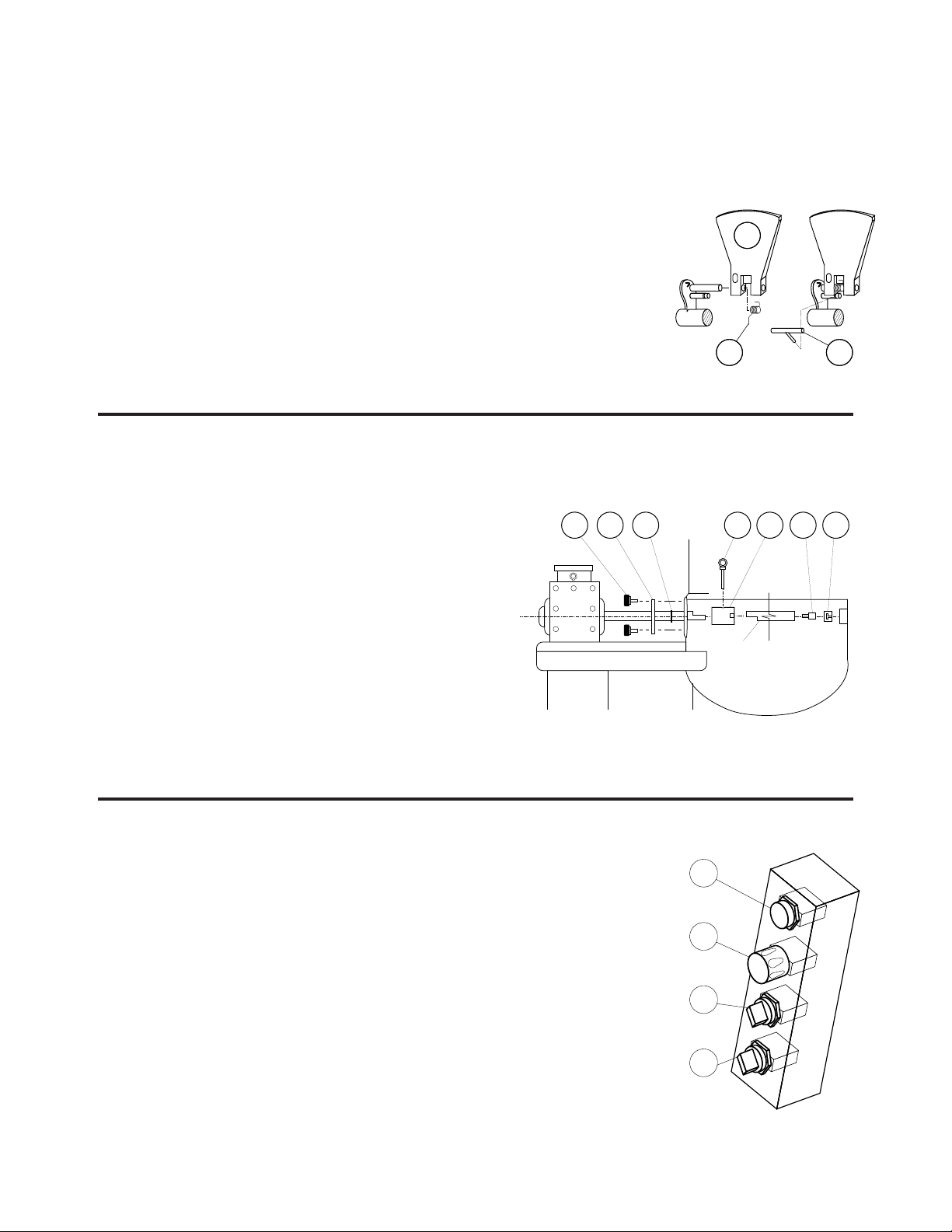
ITEM ON. PART NO. DESCRIPTION QTY.
1. KE55210 WELD RING, KETTLE BOTTOM OUTLET . . . . . . . . . . . . . . . . . . . . . . . . . . . . . 1
2. FI05144-3 SANI CLAMP, 3” . . . . . . . . . . . . . . . . . . . . . . . . . . . . . . . . . . . . . . . . . . . . . . . . . 2
3. KE52154-4 GASKET, SANI CLAMP, 3” . . . . . . . . . . . . . . . . . . . . . . . . . . . . . . . . . . . . . . . . . 2
4. KE02291 COMPLETE ACTUATOR AND DISCHARGE VALVE ASSEMBLY . . . . . . . . . . . . 1
INCLUDES PARTS 5. - 13.
5. KE55248 BUNA-N O-RING . . . . . . . . . . . . . . . . . . . . . . . . . . . . . . . . . . . . . . . . . . . . . . . . .1
6. KE55249 REPLACEABLE S.S. PLUNGER HEAD . . . . . . . . . . . . . . . . . . . . . . . . . . . . . . . .1
7. KE55250 BUNA-N O-RING . . . . . . . . . . . . . . . . . . . . . . . . . . . . . . . . . . . . . . . . . . . . . . . . .1
8. KE55251 1/8 NPT S.S. HYDRAULIC CLOSE NIPPLE . . . . . . . . . . . . . . . . . . . . . . . . . . . .2
9. KE55252 MALE S.S. QUICK DISCONNECT . . . . . . . . . . . . . . . . . . . . . . . . . . . . . . . . . . . .1
10. KE55253 AIR OPERATED CYLINDER . . . . . . . . . . . . . . . . . . . . . . . . . . . . . . . . . . . . . . . .1
11. KE55254 FEMALE S.S. QUICK DISCONNECT . . . . . . . . . . . . . . . . . . . . . . . . . . . . . . . . .1
12. FA05002-53 BUNA-N O-RING . . . . . . . . . . . . . . . . . . . . . . . . . . . . . . . . . . . . . . . . . . . . . . . . .2
13. KE55256 FEMALE S.S. QUICK DISCONNECT . . . . . . . . . . . . . . . . . . . . . . . . . . . . . . . . .1
14. KE54924 TEMPERATURE SENSOR ASSEMBLY . . . . . . . . . . . . . . . . . . . . . . . . . . . . . . . . 1
15. FA05002-46 O-RING, FOOD GRADE, SIZE A0123, EPDM E 692-75 . . . . . . . . . . . . . . . . . . 1
16. KE52154-3 GASKET, SANI CLAMP, 1 1/2” WHITE TEFLON . . . . . . . . . . . . . . . . . . . . . . . . . 1
1
15
16
3
2
12
13
12
5
6
7
8
10
9
8
11
TEMPERATURE
SENSOR
4
AIR VALVE
ASSEMBLY
FPVA-3
14
FLUSH PISTON VALVE
& TEMPERATURE
SENSOR ASSEMBLIES
(USED AFTER TO 2003)
Page 20

GEARMOTOR - ELECTRICAL ASSEMBLY
5
3
4
2
1
6
7
8
ITEM NO. PART NO. DESCRIPTION QTY.
1. KE53838-2 TRANSFORMER, 200-240V/440-480V . . . . . . . . . . . . . . . . . . . . . . . . . . . . . . . .1
2. KE50750-2 CONTACTOR . . . . . . . . . . . . . . . . . . . . . . . . . . . . . . . . . . . . . . . . . . . . . . . . . . . .1
3. KE51139-1 FUSE HOLDER . . . . . . . . . . . . . . . . . . . . . . . . . . . . . . . . . . . . . . . . . . . . . . . . . .3
4. KE52936-18 15A FUSE, KLKR . . . . . . . . . . . . . . . . . . . . . . . . . . . . . . . . . . . . . . . . . . . . . . . . .3
5. PR50003 TERMINAL BLOCK
6. PR50005 TERMINAL BLOCK BRACKET . . . . . . . . . . . . . . . . . . . . . . . . . . . . . . . . . . . . . .1
7. KE54528 A.C. INVERTER . . . . . . . . . . . . . . . . . . . . . . . . . . . . . . . . . . . . . . . . . . . . . . . . . .1
8. KE54527-1 GEAR MOTOR, 200V/340V . . . . . . . . . . . . . . . . . . . . . . . . . . . . . . . . . . . . . . . . .1
KE54527-2 GEAR MOTOR, 230V/460V . . . . . . . . . . . . . . . . . . . . . . . . . . . . . . . . . . . . . . . . .1
Page 21

KETTLE - ELECTRICAL COMPONENTS
ITEM ON. PART NO. DESCRIPTION QTY.
1. KE53838-19 TRANSFORMER, 120-16V. . . . . . . . . . . . . . . . . . . . . . . . . . . . . . . . . . . . . . . . . .1
KE53444 TRANSFORMER BRACKET . . . . . . . . . . . . . . . . . . . . . . . . . . . . . . . . . . . . . . . . .1
2. KE54833-3 BUSHING . . . . . . . . . . . . . . . . . . . . . . . . . . . . . . . . . . . . . . . . . . . . . . . . . . . . . .1
3. KE02372 IGNITION MODULE, PRIOR TO SEPT. 2004 . . . . . . . . . . . . . . . . . . . . . . . . . . .1
KE53469-4 IGNITION MODULE, SEPT. 2004 AND AFTER . . . . . . . . . . . . . . . . . . . . . . . . . .1
4. KE00458 SOLID STATE CONTROL . . . . . . . . . . . . . . . . . . . . . . . . . . . . . . . . . . . . . . . . . .1
KE50303 SOLID STATE CONTROL BRACKET . . . . . . . . . . . . . . . . . . . . . . . . . . . . . . . . . .1
5. KE50753-7 RELAY . . . . . . . . . . . . . . . . . . . . . . . . . . . . . . . . . . . . . . . . . . . . . . . . . . . . . . . . .1
6. KE55069-6 SAFETY THERMOSTAT . . . . . . . . . . . . . . . . . . . . . . . . . . . . . . . . . . . . . . . . . . . .1
7. FI05050 BRASS NUT #7/16-24 . . . . . . . . . . . . . . . . . . . . . . . . . . . . . . . . . . . . . . . . . . . . .1
8. KE02400 AIR SWITCH, PRIOR TO SEPT. 2004 . . . . . . . . . . . . . . . . . . . . . . . . . . . . . . . . .1
KE55453-1 AIR SWITCH, SEPT. 2004 AND AFTER . . . . . . . . . . . . . . . . . . . . . . . . . . . . . . . .1
9. KE53838-20 TRANSFORMER 120-24V . . . . . . . . . . . . . . . . . . . . . . . . . . . . . . . . . . . . . . . . . .1
Page 22

KETTLE - GAS COMPONENTS
14
4
3
2
6
7
8
9
5
12
26
10 26
11
20
13
25
16
15
17
18
1
24
23
22
19
21
26
Page 23

ITEM ON. PART NO. DESCRIPTION QTY.
1. KE53617 SIGHT GLASS . . . . . . . . . . . . . . . . . . . . . . . . . . . . . . . . . . . . . . . . . . . . . . . . . . .1
2. KE53437 IGNITOR . . . . . . . . . . . . . . . . . . . . . . . . . . . . . . . . . . . . . . . . . . . . . . . . . . . . . . .1
3. KE50556-2 WATER LEVEL PROBE . . . . . . . . . . . . . . . . . . . . . . . . . . . . . . . . . . . . . . . . . . . .1
4. KE00515 THERMISTOR . . . . . . . . . . . . . . . . . . . . . . . . . . . . . . . . . . . . . . . . . . . . . . . . . . .1
5. FI05213 PLUG . . . . . . . . . . . . . . . . . . . . . . . . . . . . . . . . . . . . . . . . . . . . . . . . . . . . . . . . . .1
6. FA05002-4 “O” RING . . . . . . . . . . . . . . . . . . . . . . . . . . . . . . . . . . . . . . . . . . . . . . . . . . . . . . .1
7. KE53422 SPRING . . . . . . . . . . . . . . . . . . . . . . . . . . . . . . . . . . . . . . . . . . . . . . . . . . . . . . . .1
8. GAS ORIFICE:
KE53403-6 NATURAL GAS - SEA LEVEL TO 2000' . . . . . . . . . . . . . . . . . . . . . . . . . . . . . . .1
KE53403-7 PROPANE GAS - SEA LEVEL TO 2000' . . . . . . . . . . . . . . . . . . . . . . . . . . . . . . .1
KE53403-10 NATURAL GAS - 2000' TO 4000' . . . . . . . . . . . . . . . . . . . . . . . . . . . . . . . . . . . .1
KE53403-11 PROPANE GAS - 2000' TO 4000' . . . . . . . . . . . . . . . . . . . . . . . . . . . . . . . . . . . .1
KE53403-10 NATURAL GAS - 4000' TO 6000' . . . . . . . . . . . . . . . . . . . . . . . . . . . . . . . . . . . .1
KE53403-14 PROPANE GAS - 4000' TO 6000' . . . . . . . . . . . . . . . . . . . . . . . . . . . . . . . . . . . .1
KE53403-17 NATURAL GAS - 6000' TO 8000' . . . . . . . . . . . . . . . . . . . . . . . . . . . . . . . . . . . .1
KE53403-18 PROPANE GAS - 6000' TO 8000' . . . . . . . . . . . . . . . . . . . . . . . . . . . . . . . . . . . .1
KE53403-17 NATURAL GAS - 8000' TO 10,000' . . . . . . . . . . . . . . . . . . . . . . . . . . . . . . . . . . .1
KE53403-22 PROPANE GAS - 8000' TO 10,000' . . . . . . . . . . . . . . . . . . . . . . . . . . . . . . . . . .1
9. FA05002-29 “O” RING . . . . . . . . . . . . . . . . . . . . . . . . . . . . . . . . . . . . . . . . . . . . . . . . . . . . . . .1
10. KE50568-1 L.E.D. GREEN . . . . . . . . . . . . . . . . . . . . . . . . . . . . . . . . . . . . . . . . . . . . . . . . . . .1
11. KE50567-1 L.E.D. RED . . . . . . . . . . . . . . . . . . . . . . . . . . . . . . . . . . . . . . . . . . . . . . . . . . . . .1
12. TEMPERATURE CONTROL ASSEMBLY:
KE50569-1 KNOB . . . . . . . . . . . . . . . . . . . . . . . . . . . . . . . . . . . . . . . . . . . . . . . . . . . . . . . . .1
SE00114 POTENTIOMETER WITH ON/OFF SWITCH, C/W SEAL . . . . . . . . . . . . . . . . . . .1
KE51005 SEAL . . . . . . . . . . . . . . . . . . . . . . . . . . . . . . . . . . . . . . . . . . . . . . . . . . . . . . . . . .1
13. KE50429-2 PRESSURE GAUGE . . . . . . . . . . . . . . . . . . . . . . . . . . . . . . . . . . . . . . . . . . . . . .1
14. KE53441 BLOWER, 110 V, 60 HZ . . . . . . . . . . . . . . . . . . . . . . . . . . . . . . . . . . . . . . . . . . . .1
15. KE53441-1 BLOWER, 220 V, 50 HZ . . . . . . . . . . . . . . . . . . . . . . . . . . . . . . . . . . . . . . . . . . . .1
16. KE01426-1 MIXING CHAMBER, 60 GALLON KETTLES . . . . . . . . . . . . . . . . . . . . . . . . . . . .1
17. KE53402-1 AIR ORIFICE, 190K BTU BURNER . . . . . . . . . . . . . . . . . . . . . . . . . . . . . . . . . . .1
18. FI05212 PIPE . . . . . . . . . . . . . . . . . . . . . . . . . . . . . . . . . . . . . . . . . . . . . . . . . . . . . . . . . . .1
19. KE95087-1 OPERATING INSTRUCTION LABEL . . . . . . . . . . . . . . . . . . . . . . . . . . . . . . . . . .1
20. KE50567-2 L.E.D. AMBER (USED PRIOR TO JULY 2004) . . . . . . . . . . . . . . . . . . . . . . . . . .1
21. KE02274 CAPACITOR ASSEMBLY . . . . . . . . . . . . . . . . . . . . . . . . . . . . . . . . . . . . . . . . . . .1
22. KE53618 SIGHT GLASS GASKET . . . . . . . . . . . . . . . . . . . . . . . . . . . . . . . . . . . . . . . . . . .1
23. KE53619 SIGHT GLASS RETAINER . . . . . . . . . . . . . . . . . . . . . . . . . . . . . . . . . . . . . . . . . .1
24. KE53570 GASKET FOR IGNITOR . . . . . . . . . . . . . . . . . . . . . . . . . . . . . . . . . . . . . . . . . . .1
25. KE54420 AIR INTAKE WASHER (NATURAL GAS) . . . . . . . . . . . . . . . . . . . . . . . . . . . . . . .1
KE54420-1 AIR INTAKE WASHER (PROPANE) . . . . . . . . . . . . . . . . . . . . . . . . . . . . . . . . . . .1
26. FA05002-18 "O" RING . . . . . . . . . . . . . . . . . . . . . . . . . . . . . . . . . . . . . . . . . . . . . . . . . . . . . . .3
Page 24

CONTROL BOX - ELECTRICAL
For front panel control switches see SIDE BOX - TILT MECHANISM & SWITCHES.
CONTROL BOX - WATER METER & CHART RECORDER.
5
14
15
4
19
33
34
35
1
1612
2
37
3938
40
2928
3231
23
20
24
2625
22
36
20
1
7
6
3
8
12
16
27
28
9 9B9C
SAFETY
SWITCH
ASSEMBLY FRONT
VIEW
SAFETY
SWITCH
ASSEMBLY -
SIDE
VIEW
13 17 18 10 16 11 12 13
DOOR
GASKET
29
30
31
Page 25

ITEM ON. PART NO. DESCRIPTION QTY.
1. KE55287-1 PANEL, REMOTE CONTROL, DUAL FLOOR . . . . . . . . . . . . . . . . . . . . . . . . . . .1
KE55187-2 PANEL, REMOTE CONTROL, DUAL WALL . . . . . . . . . . . . . . . . . . . . . . . . . . . .1
KE55287-3 PANEL, REMOTE CONTROL SINGLE FLOOR . . . . . . . . . . . . . . . . . . . . . . . . . .1
KE55287-4 PANEL, REMOTE CONTROL, SINGLE WALL . . . . . . . . . . . . . . . . . . . . . . . . . . .1
2. KE55284-1 COMPONENT MOUNTING PLATE DUAL PANEL . . . . . . . . . . . . . . . . . . . . . . . .1
KE55284-2 COMPONENT MOUNTING PLATE SINGLE PANEL . . . . . . . . . . . . . . . . . . . . . .1
3. KE55286-1 MOUNTING BRACKET, INCOMING, DUAL PANEL . . . . . . . . . . . . . . . . . . . . . .1
KE55286-2 MOUNTING BRACKET, INCOMING, SINGLE PANEL . . . . . . . . . . . . . . . . . . . .1
4. KE54860 FAN . . . . . . . . . . . . . . . . . . . . . . . . . . . . . . . . . . . . . . . . . . . . . . . . . . . . . . . . . . .2
5. KE55283 VENT COVER PLATE . . . . . . . . . . . . . . . . . . . . . . . . . . . . . . . . . . . . . . . . . . . . . .4
6. KE55288-1 MOUNTING RAIL, DUAL CONTROL PANEL . . . . . . . . . . . . . . . . . . . . . . . . . . .1
KE55288-2 MOUNTING RAIL SINGLE CONTROL PANEL . . . . . . . . . . . . . . . . . . . . . . . . . .1
7. KE55298 MOTOR PROTECTOR SWITCH . . . . . . . . . . . . . . . . . . . . . . . . . . . . . . . . . . . . .2/1
8. KE50750-4 CONTACTOR, 230 VAC, 50 AMP . . . . . . . . . . . . . . . . . . . . . . . . . . . . . . . . . . . .1
KE50750-2 CONTACTOR, 230 VAC, 30 AMP . . . . . . . . . . . . . . . . . . . . . . . . . . . . . . . . . . . .1
9. KE55297-1 SAFETY INTERLOCK SWITCH . . . . . . . . . . . . . . . . . . . . . . . . . . . . . . . . . . . . . .1
9B. KE55297-2 TOTALLY FLEXIBLE ACTUATOR . . . . . . . . . . . . . . . . . . . . . . . . . . . . . . . . . . . . .1
9C. KE55297-3 GD2 STANDARD ACTUATOR . . . . . . . . . . . . . . . . . . . . . . . . . . . . . . . . . . . . . . .1
10. KE55285 MOUNTING BRACKET, DOOR INTERLOCK SWITCH . . . . . . . . . . . . . . . . . . . .1
11. FA40000-15 WELD STUD, #10-32 X 1/2, S.S. . . . . . . . . . . . . . . . . . . . . . . . . . . . . . . . . . . . . .4
12. FA21007 HEX NUT, #10-32, S.S. . . . . . . . . . . . . . . . . . . . . . . . . . . . . . . . . . . . . . . . . . . . .4
13. FA32006 TOOTH LOCK WASHER, #10, S.S. . . . . . . . . . . . . . . . . . . . . . . . . . . . . . . . . . .6
14. FA11091 SCREW, #8-32 X 3/8, S.S. . . . . . . . . . . . . . . . . . . . . . . . . . . . . . . . . . . . . . . . . .16
15. FA21004 NUT, #8-32, S.S. . . . . . . . . . . . . . . . . . . . . . . . . . . . . . . . . . . . . . . . . . . . . . . . . .16
16. FA11146 SCREW, #10-32 X 1/2, S.S. . . . . . . . . . . . . . . . . . . . . . . . . . . . . . . . . . . . . . . .11/8
17. FA40000-14 WELD STUD, #10-24 X 3/4, S.S. . . . . . . . . . . . . . . . . . . . . . . . . . . . . . . . . . . . . .2
18. FA21006 HEX NUT, #10-24, S.S. . . . . . . . . . . . . . . . . . . . . . . . . . . . . . . . . . . . . . . . . . . . .2
19. KE55271 LABEL, REMOTE CONTROL PANEL . . . . . . . . . . . . . . . . . . . . . . . . . . . . . . . . .2/1
20. KE55292-1 LABEL TERMINAL STRIP REMOTE PANEL . . . . . . . . . . . . . . . . . . . . . . . . . . . .1
21. KE55292-4 LABEL TERMINAL STRIP REMOTE PANEL . . . . . . . . . . . . . . . . . . . . . . . . . . . .1
22. KE55292-3 LABEL, TERMINAL STRIP, REMOTE PANEL . . . . . . . . . . . . . . . . . . . . . . . . . . .1
23. KE50753-10 RELAY, 120 V HOT COLD WATER BYPASS . . . . . . . . . . . . . . . . . . . . . . . . . . .6/3
24. KE52106 TERMINAL BLOCK . . . . . . . . . . . . . . . . . . . . . . . . . . . . . . . . . . . . . . . . . . . . . .4/2
25. KE50377 TERMINAL BLOCK . . . . . . . . . . . . . . . . . . . . . . . . . . . . . . . . . . . . . . . . . . . . . . .4
26. KE50376 TERMINAL BLOCK END . . . . . . . . . . . . . . . . . . . . . . . . . . . . . . . . . . . . . . . . . . .1
27. KE50374 TERMINAL BLOCK MOUNTING BRACKET . . . . . . . . . . . . . . . . . . . . . . . . . . .2/1
28. SK50055-1 TERMINAL BLOCK . . . . . . . . . . . . . . . . . . . . . . . . . . . . . . . . . . . . . . . . . . . . . .14/7
29. SK50054-1 TERMINAL BLOCK END . . . . . . . . . . . . . . . . . . . . . . . . . . . . . . . . . . . . . . . . . .4/2
30. KE54761-2 TERMINAL BLOCK MOUNTING RAIL . . . . . . . . . . . . . . . . . . . . . . . . . . . . . . . .2/1
31. SK50054-2 TERMINAL BLOCK END . . . . . . . . . . . . . . . . . . . . . . . . . . . . . . . . . . . . . . . . . .4/2
32. KE54761 TERMINAL BLOCK MOUNTING RAIL . . . . . . . . . . . . . . . . . . . . . . . . . . . . . . . .1
33. KE90425-1 WIRING DIAGRAM, DUAL REMOTE CONTROL PANEL . . . . . . . . . . . . . . . . . .1
KE90425-2 WIRING DIAGRAM, SINGLE REMOTE CONTROL PANEL . . . . . . . . . . . . . . . . .1
34. KE90401-2 WIRING DIAGRAM, DUAL WATER METER OPTION . . . . . . . . . . . . . . . . . . . . .1
35. KE55232 WIRING DIAGRAM, 3" AIR VALVE OPTION . . . . . . . . . . . . . . . . . . . . . . . . . . . .1
36. KE54528 AC INVERTER . . . . . . . . . . . . . . . . . . . . . . . . . . . . . . . . . . . . . . . . . . . . . . . . . .2/1
37. KE53838-2 TRANSFORMER, 200- 240V . . . . . . . . . . . . . . . . . . . . . . . . . . . . . . . . . . . . . . .2/1
38. KE52936-18 FUSE, 15 AMP . . . . . . . . . . . . . . . . . . . . . . . . . . . . . . . . . . . . . . . . . . . . . . . . . .6/3
39. KE51139-1 FUSE HOLDER . . . . . . . . . . . . . . . . . . . . . . . . . . . . . . . . . . . . . . . . . . . . . . . . .6/3
40. KE50750-2 CONTACTOR . . . . . . . . . . . . . . . . . . . . . . . . . . . . . . . . . . . . . . . . . . . . . . . . . . .2/1
Page 26

CONTROL BOX WATER METER & CHART RECORDER
ITEM NO. PART NO. DESCRIPTION QTY.
1. KE53257 Digital Counter . . . . . . . . . . . . . . . . . . . . . . . . . . . . . . . . . . . . . . . . . . . . . . . . . .1
2. SE50354 Pen Tip, red (pkg. of 5) . . . . . . . . . . . . . . . . . . . . . . . . . . . . . . . . . . . . . . . . . . .1
3. SE50354 Pen Tip, green (pkg. of 5) . . . . . . . . . . . . . . . . . . . . . . . . . . . . . . . . . . . . . . . . .1
4. KE003209-1 Switch Assembly, On/Off - Maintained . . . . . . . . . . . . . . . . . . . . . . . . . . . . . . . .1
5. KE003209-1 Switch Assembly, On/Off - Maintained . . . . . . . . . . . . . . . . . . . . . . . . . . . . . . . .2
6. KE003209-6 Momentary Spring Return Switch Assembly . . . . . . . . . . . . . . . . . . . . . . . . . . .1
7. KE003209-7 Momentary Spring Return Switch Assembly . . . . . . . . . . . . . . . . . . . . . . . . . . .2
8. KE53136-1 Chart Recorder . . . . . . . . . . . . . . . . . . . . . . . . . . . . . . . . . . . . . . . . . . . . . . . . . .1
NOTES: For units built prior to December 2006,
the complete switch assembly must be
ordered.
*
*
EMPTY
EMPTY
WATER METER
START
CONTINUE RESET
EMPTY
START
OFF ON
EMPTY
EMPTY
EMPTY
MAIN POWER
8
EMPTY
EMPTY
EMPTY
BYPASS ACTIVEOFF ON
EMPTY
EMPTY
EMPTY
INTERRUPT
EMPTY
2
3
4
5
6
INDEX
Contactor CartridgesCapacitor
7
5
INCLUDED WITH
1
ALL SWITCHES.
PART NO.
KE52074 KE603208-9 KE603208-8
Page 27

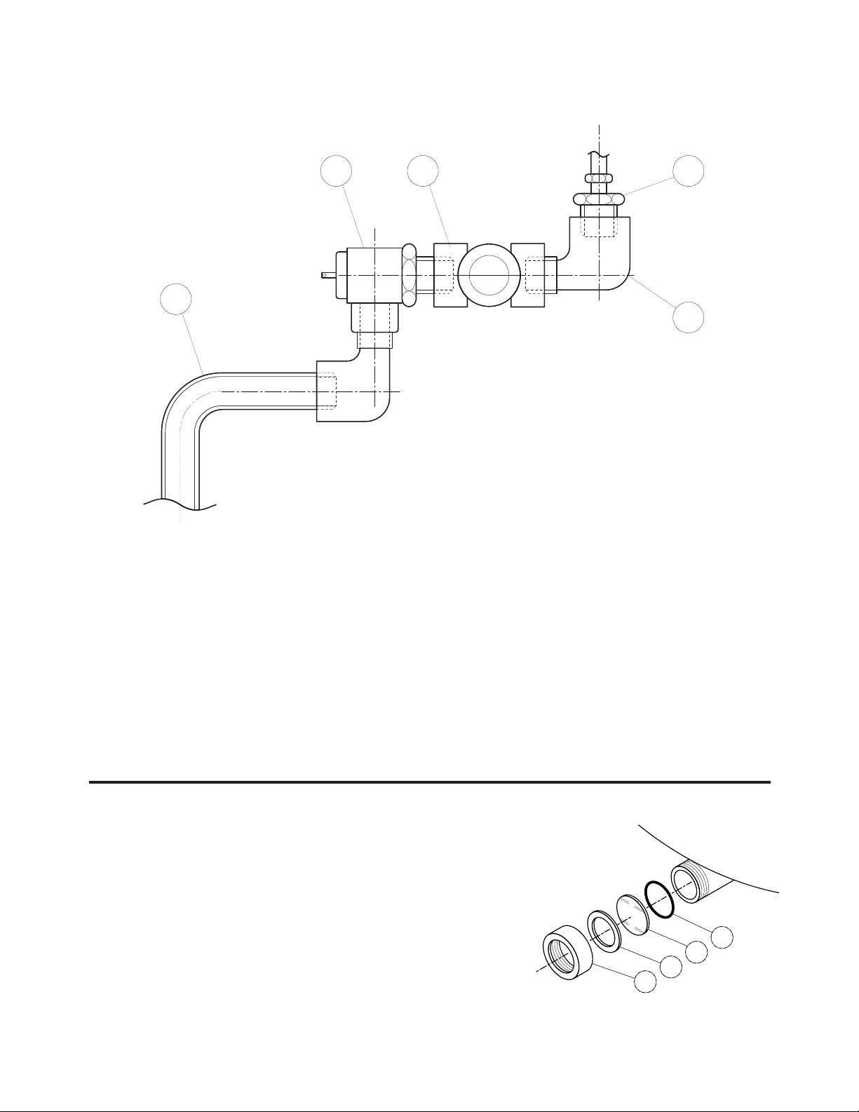
ITEM NO. PART NO. DESCRIPTION QTY.
1. FA05166 QUICK CONNECT . . . . . . . . . . . . . . . . . . . . . . . . . . . . . . . . . . . . . . . . . . . . . . . .1
2. KE54280 SLIDE VALVE . . . . . . . . . . . . . . . . . . . . . . . . . . . . . . . . . . . . . . . . . . . . . . . . . . . .I
3. FA30512 SPACER WASHER . . . . . . . . . . . . . . . . . . . . . . . . . . . . . . . . . . . . . . . . . . . . . . . .1
4. FA32500 TOOTH LOCK WASHER 7/8" DIA. . . . . . . . . . . . . . . . . . . . . . . . . . . . . . . . . . . .1
5. KE52697 NUT 1/2 NPS BRASS . . . . . . . . . . . . . . . . . . . . . . . . . . . . . . . . . . . . . . . . . . . . . .I
6. KE52931 AIR FITTING . . . . . . . . . . . . . . . . . . . . . . . . . . . . . . . . . . . . . . . . . . . . . . . . . . . .1
7. F100178 TEE 1/2 NPT . . . . . . . . . . . . . . . . . . . . . . . . . . . . . . . . . . . . . . . . . . . . . . . . . . . .1
8. FI00351 BUSHING 1/2 MIP X 1/4 FIP . . . . . . . . . . . . . . . . . . . . . . . . . . . . . . . . . . . . . . . .1
9. FI05318 HOSE BARB 90° ELBOW . . . . . . . . . . . . . . . . . . . . . . . . . . . . . . . . . . . . . . . . . .3
10. FI00151 90° STREET ELBOW 1/2 NPT . . . . . . . . . . . . . . . . . . . . . . . . . . . . . . . . . . . . . . .1
11. FA30090 WASHER 15/16 ID X 1 3/4 OD X 1/8 . . . . . . . . . . . . . . . . . . . . . . . . . . . . . . . . .1
12. 7100595-8 NIPPLE 1/2 NPT X 4 1/2" LONG . . . . . . . . . . . . . . . . . . . . . . . . . . . . . . . . . . . . .1
13. KE55238 FILTER-REGULATOR-LUBRICATOR BLOCK . . . . . . . . . . . . . . . . . . . . . . . . . . .1
14. F105220-1 GEAR CLAMP . . . . . . . . . . . . . . . . . . . . . . . . . . . . . . . . . . . . . . . . . . . . . . . . . . .4
15. FA21006 10-24 S.S. NUT . . . . . . . . . . . . . . . . . . . . . . . . . . . . . . . . . . . . . . . . . . . . . . . . . .2
16. KE532177 PNEUMATIC HOSE 1/4 I.D. X 31" L . . . . . . . . . . . . . . . . . . . . . . . . . . . . . . . . . .1
17. KE532176 PNEUMATIC HOSE 1/4 I.D. X 12 1/2" L . . . . . . . . . . . . . . . . . . . . . . . . . . . . . . .1
18. FA30000 FLAT WASHER #10, ZINC PLATED . . . . . . . . . . . . . . . . . . . . . . . . . . . . . . . . . . .2
19. KE02292 AIR SOLENOID ASSEMBLY . . . . . . . . . . . . . . . . . . . . . . . . . . . . . . . . . . . . . . . .1
20. KE50555-3 GROMMET . . . . . . . . . . . . . . . . . . . . . . . . . . . . . . . . . . . . . . . . . . . . . . . . . . . . .2
21. FA21008 1/4-20 NUT S.S. . . . . . . . . . . . . . . . . . . . . . . . . . . . . . . . . . . . . . . . . . . . . . . . . .2
22. FA30002 FLAT WASHER 1/4 DIA., ZINC PLATED . . . . . . . . . . . . . . . . . . . . . . . . . . . . . . .2
4671211
14 9 13 21 22 9
20
1716
1815
19
RTV ALL AROUND
(NOT SHOWN)
3
1
2
5
8
9
SIDE BOX PNEUMATICS
Page 28

ITEM NO. PART NO. DESCRIPTION QTY.
1. KE50579-1 CIRCUIT BREAKER . . . . . . . . . . . . . . . . . . . . . . . . . . . . . . . . . . . . . . . . . . . . . . .1
FA00012 "O" RING, CIRCUIT BREAKER . . . . . . . . . . . . . . . . . . . . . . . . . . . . . . . . . . . . . .1
KE50580 WATER RESISTANT BOOT . . . . . . . . . . . . . . . . . . . . . . . . . . . . . . . . . . . . . . . . .1
2. KE603208-4 TILT SWITCH OPERATOR . . . . . . . . . . . . . . . . . . . . . . . . . . . . . . . . . . . . . . . . . .1
3. KE51730 TILT SHAFT BEARING . . . . . . . . . . . . . . . . . . . . . . . . . . . . . . . . . . . . . . . . . . . . .1
4. KE54531 AGITATOR STOP . . . . . . . . . . . . . . . . . . . . . . . . . . . . . . . . . . . . . . . . . . . . . . . . .1
5.* KE54530 AGITATOR START . . . . . . . . . . . . . . . . . . . . . . . . . . . . . . . . . . . . . . . . . . . . . . . .1
6.* KE54529 POWER ON/OFF SWITCH . . . . . . . . . . . . . . . . . . . . . . . . . . . . . . . . . . . . . . . . . .1
7.* KE54532 SPEED CONTROL . . . . . . . . . . . . . . . . . . . . . . . . . . . . . . . . . . . . . . . . . . . . . . . .1
8. KE01889 MICRO SWITCH TRIGGER/SEGMENT GEAR WELDMENT . . . . . . . . . . . . . . . .1
43
8
10
11
12
13
14
15
16
17
18
19
18
20
18
19
18
17
21
2322
24
36
37
38
39
35
31
32
30
33
34
44
25 26 27 28
29
42
50
51
52
GAS CONNECTIONGAS CONNECTION
SEE PNEUMATIC
COMPONENTS DRAWING
SEE PNEUMATIC
COMPONENTS DRAWING
48
47
46
45
49
9
3
5
4
7
6
2
40
41
1
53
54
55
56
SIDE BOX TILT MECHANISM
& SWITCHES
Page 29

9. FA10772 SOCKET HD. CAP SCREW . . . . . . . . . . . . . . . . . . . . . . . . . . . . . . . . . . . . . . . . .2
10. FA20048 JAM NUT . . . . . . . . . . . . . . . . . . . . . . . . . . . . . . . . . . . . . . . . . . . . . . . . . . . . . . .2
11. FA95007-4 RETAINING RING . . . . . . . . . . . . . . . . . . . . . . . . . . . . . . . . . . . . . . . . . . . . . . . .1
12. FA95055-1 SQUARE KEY . . . . . . . . . . . . . . . . . . . . . . . . . . . . . . . . . . . . . . . . . . . . . . . . . . .1
13. FA19201 HEX SOCKET SET SCREW 3/8-24 . . . . . . . . . . . . . . . . . . . . . . . . . . . . . . . . . . .1
14. KE54644 TILT SHAFT, MANUAL TILT . . . . . . . . . . . . . . . . . . . . . . . . . . . . . . . . . . . . . . . . .1
KE52836-2 TILT SHAFT, POWER TILT . . . . . . . . . . . . . . . . . . . . . . . . . . . . . . . . . . . . . . . . . .1
15. KE50315 WORM . . . . . . . . . . . . . . . . . . . . . . . . . . . . . . . . . . . . . . . . . . . . . . . . . . . . . . . . .1
16. FA95005 TENSION PIN . . . . . . . . . . . . . . . . . . . . . . . . . . . . . . . . . . . . . . . . . . . . . . . . . . .1
17. KE52193-1 THRUST BEARING SPACER . . . . . . . . . . . . . . . . . . . . . . . . . . . . . . . . . . . . . . . .2
18. KE52192 THRUST WASHER . . . . . . . . . . . . . . . . . . . . . . . . . . . . . . . . . . . . . . . . . . . . . . . .4
19. KE52191 ROLLER BEARING . . . . . . . . . . . . . . . . . . . . . . . . . . . . . . . . . . . . . . . . . . . . . . .2
20. FA30088 WASHER . . . . . . . . . . . . . . . . . . . . . . . . . . . . . . . . . . . . . . . . . . . . . . . . . . . . . . .2
21. FA95008 JAM NUTS . . . . . . . . . . . . . . . . . . . . . . . . . . . . . . . . . . . . . . . . . . . . . . . . . . . . . .2
22. KE50582 CPLG. ONTARIO BELTING #G-100 5/8 BORE . . . . . . . . . . . . . . . . . . . . . . . . . .2
23. FA95055-6 SQUARE KEY 3/16 X 3/16 X 1" LG . . . . . . . . . . . . . . . . . . . . . . . . . . . . . . . . . . .1
24. KE50583 RUBBER INSERT, ONTARIO BELTING "BUNA N" . . . . . . . . . . . . . . . . . . . . . . . .1
25. KE52832-1 MOTOR "BODINE" . . . . . . . . . . . . . . . . . . . . . . . . . . . . . . . . . . . . . . . . . . . . . . . .1
26. FA10487 HEX HD SCREW 1/4-20 X 1" LG . . . . . . . . . . . . . . . . . . . . . . . . . . . . . . . . . . . . .4
27. FA31008 SPLIT LOCKWASHER 1/4" DIA . . . . . . . . . . . . . . . . . . . . . . . . . . . . . . . . . . . . . .4
28. FA20026 HEX NUT 1/4 - 20 . . . . . . . . . . . . . . . . . . . . . . . . . . . . . . . . . . . . . . . . . . . . . . . .4
29. KE50473 GROUND LUG . . . . . . . . . . . . . . . . . . . . . . . . . . . . . . . . . . . . . . . . . . . . . . . . . .1
30. FO1518-1 GAS SHUT-OFF VALVE . . . . . . . . . . . . . . . . . . . . . . . . . . . . . . . . . . . . . . . . . . . .1
31. KE02053 COMBINATION GAS VALVE NATURAL GAS . . . . . . . . . . . . . . . . . . . . . . . . . . .1
32. FI05223-1 SPECIAL NIPPLE . . . . . . . . . . . . . . . . . . . . . . . . . . . . . . . . . . . . . . . . . . . . . . . . .1
33. FI05222 SWIVEL ELBOW . . . . . . . . . . . . . . . . . . . . . . . . . . . . . . . . . . . . . . . . . . . . . . . . .1
34. FI05231 FLUSH BUSHING 3/4M TO1/2F . . . . . . . . . . . . . . . . . . . . . . . . . . . . . . . . . . . . .1
35. FI05226-11 NIPPLE 1/2 X 10" LG . . . . . . . . . . . . . . . . . . . . . . . . . . . . . . . . . . . . . . . . . . . . . .1
36. KE51007 MICRO SWITCH . . . . . . . . . . . . . . . . . . . . . . . . . . . . . . . . . . . . . . . . . . . . . . . . .2
37. FA10139 MACHINE SCREW #6-32 X 1" LG . . . . . . . . . . . . . . . . . . . . . . . . . . . . . . . . . . . .4
38. KE50498 MICRO SWITCH INSULATION . . . . . . . . . . . . . . . . . . . . . . . . . . . . . . . . . . . . . .2
39. FA32004 TOOTH LOCK WASHER #6 . . . . . . . . . . . . . . . . . . . . . . . . . . . . . . . . . . . . . . . .4
40. KE603208-7 CONTACT SECTION HOLDER (LATCH) . . . . . . . . . . . . . . . . . . . . . . . . . . . . . . .1
41. KE603208-9 CONTACT BLOCK . . . . . . . . . . . . . . . . . . . . . . . . . . . . . . . . . . . . . . . . . . . . . . .4
42. KE50581 BRIDGE RECTIFIER . . . . . . . . . . . . . . . . . . . . . . . . . . . . . . . . . . . . . . . . . . . . . .1
43. KE54535 EDGE CONNECTOR (11 PIN) . . . . . . . . . . . . . . . . . . . . . . . . . . . . . . . . . . . . . . .2
44. KE50753-10 RELAY . . . . . . . . . . . . . . . . . . . . . . . . . . . . . . . . . . . . . . . . . . . . . . . . . . . . . . . . .2
45. KE54491 LID FOR GEARBOX . . . . . . . . . . . . . . . . . . . . . . . . . . . . . . . . . . . . . . . . . . . . . .1
46. KE53599-8 GASKET . . . . . . . . . . . . . . . . . . . . . . . . . . . . . . . . . . . . . . . . . . . . . . . . . . . . . . .2
47. KE53599-9 GASKET . . . . . . . . . . . . . . . . . . . . . . . . . . . . . . . . . . . . . . . . . . . . . . . . . . . . . . .2
48. FA95062 PAN HD. PHILLIPS SCREW . . . . . . . . . . . . . . . . . . . . . . . . . . . . . . . . . . . . . . . .4
49. FA95074 NYLON ANCHOR NUT . . . . . . . . . . . . . . . . . . . . . . . . . . . . . . . . . . . . . . . . . . . .1
50. FA19177 HEX SOCKET SET SCREW 5/16-24 X 1" . . . . . . . . . . . . . . . . . . . . . . . . . . . . . .1
51. FA20047 JAM NUT 5/16-24 . . . . . . . . . . . . . . . . . . . . . . . . . . . . . . . . . . . . . . . . . . . . . . . .1
52. KE54606 GAS VALVE LOCKWASHER . . . . . . . . . . . . . . . . . . . . . . . . . . . . . . . . . . . . . . . .1
53. KE003209-9 SWITCH, JOG TO OPEN AIR VALVE . . . . . . . . . . . . . . . . . . . . . . . . . . . . . . . . .1
54.* KE003209-6 SWITCH, FILL INTERRUPT . . . . . . . . . . . . . . . . . . . . . . . . . . . . . . . . . . . . . . . . .1
55. * KE003209-2 SWITCH, HOT/COLD SELECTION . . . . . . . . . . . . . . . . . . . . . . . . . . . . . . . . . . .1
56.* KE003209-3 SWITCH, FILL CYCLE . . . . . . . . . . . . . . . . . . . . . . . . . . . . . . . . . . . . . . . . . . . . .1
* SWITCHES MAY BE LOCATED ON REMOTE CONTROL PANEL.
Page 30

MAINTENANCE
INSPECTION AND MAINTENANCE CHECKLIST
Cleveland Range equipment requires little preventative maintenance. We do however provide the following chart as a
guide line for inspection and maintenance to keep your unit functioning at 100%.
MONTHLY INSPECTION
Inspect all switches for damage. Replace rubber boots or switches as required.
Check that the automatic dump valve works fully and smoothly and no air leaks are evident.
Check that the 3 way regulator shuts off the incoming air and completely vacates the air from the air hose to the
metering filling station.
Tilt kettle and check for smooth operation in both directions.
Inspect gear and worm assembly in gear box for play - tighten Allen screws if required.
Inspect gasket material on covers for integrity.
Check spring assist covers for tightness to handle and insure spring is holding cover up - adjust if required. Refer to
HINGE ADJUSTMENT INSTRUCTIONS.
When kettle is cold check that pressure gauge needle is in the green zone indicating a vacuum in kettle - if
venting is required refer to KETTLE VENTING PROCEDURE.
Inspect mixer blades for cracks or other damage - replace as required. Refer to NEW SCRAPER BLADE
INSTALLATION PROCEDURE.
Check quad ring and replace if required. Refer to QUAD RING REPLACEMENT PROCEDURE.
Inspect oiler in gear box and fill with oil if required. Refer to OILER FILLING PROCEDURE.
Inspect air filter cartridge and replace if required. Refer to AIR FILTER REPLACEMENT PROCEDURE.
SIX MONTH MAINTENANCE
Grease trunnion housings in gear box and on outboard bearings.
Test pressure relief valve. Refer to PRESSURE RELIEF VALVE TESTING PROCEDURE.
Page 31

OPERATING SEQUENCE - HEATING
QUICK CHECKS:
Potentiometer - Range 0 - 50K, Safety Thermostat - Normally Closed,
Thermistor - Range 0 - 100K, Water Level Probe - Must be submerged in water for burners to work
RESULT 2
Amber LED is illuminated.
(Used prior to July 2004)
a/ Green LED illuminates.
b/ 12 VDC relay contacts close.
a/ Air switch contacts close.
a/
25 volts supplied to ignition module.
Within 20 seconds ignitor glows red.
a/ Burner ignites.
a/ If temperature drops in
chamber gas valve is deenergized within five seconds.
b/ Ignitor will try twice more to
light before locking out.
a/ Green LED turns off.
b/ 12 VDC relay contacts open.
c/ Blower turns off.
d/
25 volt transformer de-energizes.
ACTION
Close main circuit breaker.
On/Off switch on kettle
switched to ON.
Control box.
12 VDC relay contacts
close.
Ignition module.
120 volts turned off to ignitor.
Temperature reached.
STEP
1.
2.
3.
4.
5.
6.
7.
RESULT 1
120 volts is supplied by primary contactor
to kettle On/Off switch and tilt relay
contacts. Power supplied to tilt assembly.
120/16 volt transformer supplies
power to control boxes.
A/ Requires grounded probe to
function (pin #5).
B/
More that 6 volts at pin #2. Control box
energizes 12 volt DC relay (pin #6).
A/ Blower energizes.
B/ 120/25 volt transformer energizes.
C/
120 volt supplied to ignition module.
Supplies 120 volts to ignition.
A/ Gas valve is energized.
B/ Ignitor becomes sensor.
A/ Less than 6 volts at pin #2.
Control box de-energizes 12 volt
DC relay (pin #6)
OPERATING SEQUENCE - AGITATOR
A/
Three phase contactor closes to
supply power to variable speed drive.
A/ Power to agitator motor.
A/ Motor speed increases.
a/ Indicator light is energized.
a/ Motor comes up to speed.
On/Off switch closed.
Start button momentarily depressed.
Speed control turned up.
1.
2.
3.
OPERATING SEQUENCE - POWER TILT
A/ Relay 2 is energized.
A/ Power interrupted to down side
of tilt switch.
A/ Relay 1 is energized.
A/ Power interrupted to up side of
tilt switch.
a/ Tilt motor is energized.
a/ Relay de-energized.
b/ Motor stops.
a/ Tilt motor is energized.
a/ Relay de-energized.
b/ Motor stops.
Turn and hold tilt switch in
down position.
Kettle tilts until limit switch is
depressed.
Turn and hold tilt switch in up
position.
Kettle tilts until limit switch is
depressed.
1.
2.
3.
4.
Page 32

KETTLE SAFETY INSPECTION CHECKLIST
Regular inspection and maintenance of units is essential to obtain trouble free and safe operation of
equipment. Inspections must include testing of the pressure relief valve and checks of the operating
system to insure that it has not been altered.
No safety features designed into the equipment should ever be tampered with. Tampering
with or bypassing controls is a very dangerous practice and unfortunately we have seen several cases of
this. Following is a short list of the most common and the most dangerous alterations performed on kettles.
✘
Plug
✘
Tube
diameter
reduced
✘
Frozen,
stuck, or
plugged
✘
Plumbed to
drain or
water line
1
2
3
4
✔
Incorrect Installations
1
Safety valve has plug threaded into the
discharge opening preventing any steam from
escaping.
2
Safety valve’s tube diameter has been
reduced.
3
Safety valve is sticking, frozen shut or plugged.
To test, refer to PRESSURE RELIEF VALVE
PERIODIC TESTING.
4
Safety valve is plumbed to a drain or water
line creating back pressure and reducing flow.
SAFETY VALVE:
This illustrations show the
correct configuration of a
factory installed Safety Valves.
Any modifications are
unacceptable.
Page 33

SAFETY THERMOSTAT:
✘
Probe
removed
partially
✘
Probe
removed
completely
✘
Thermostat
electrically
bypassed
✔
Probe
fully
inserted
in tube
Wiring is properly
connected
123
Incorrect
Installations
1
Safety thermostat
probe is not
completely
inserted into
tubing.
2
Safety thermostat
probe is removed
from tubing.
3
Safety thermostat
electrical
connection is
bypassed.
Low Water Level Probe:
Probe bypassed by
running (A) an
additional wire
Probe properly
attached
260º - 270º
MAXIMUM
KETTLE
TEMPERATURE
265º
✔
If maximum temperature
is not in this range (on
empty kettle), refer to the
CALIBRATING
PROCEDURE.
Operating
Thermostat:
✔
✘
Probe bypassed by
(B) grounding the
connecting wire
✘
(A)
(B)
✘
Switch
electrically
bypassed
✔
Wiring is
properly
connected
Air
Switch:
Incorrect
Installation
Page 34

NEW SCRAPER BLADE
INSTALLATION PROCEDURE
Fig. 2 Fig. 3Fig. 1
Scraper
blade
Back stop
Move to
adjust
Move to
adjust
Trim corners or
center to fit
Spring
QUAD RING REPLACEMENT
PROCEDURE
1. Remove agitator as per cleaning instructions.
2. Remove hole cap, retaining bolt and retaining
washer.
3. Snap retaining ring out from seating inside motor.
4. Remove retaining knobs.
5. Slide seal retainer plate away from kettle.
6. Slide shaft away from kettle body to allow
clearance for removing quad ring.
7. Remove quad ring.
8. Slide new quad ring back into original position,
making sure it does not twist.
9. Apply light coat of food-safe grease.
10.
Slide retainer plate back toward kettle, replacing
retaining knobs -tighten with hand pressure only.
11. Reassemble.
Retaining ring
Hole cap
Retaining bolt
Retaining washer
Retaining
ring seat
Quad ring
Seal retainer plate
Retaining knobs
AIR FILTER REPLACEMENT
PROCEDURE
1 Disconnect air supply and bleed system.
2. Remove cover on console (see SIDE BOX -
PNEUMATICS).
3. Check for filter location.
4. Push lever down
and rotate bowl/
guard assembly
1/8 turn.
5. Push down on
bowl/guard
assembly
and remove.
6. Unscrew baffle
and remove filter
element, inspect
and replace filter
if required.
7. Replace filler cap
and cover.
Deflector
Filter
Element
Baffle
Lever
Bowl/Guard
Assembly
LUBRICATION PROCEDURE
Lubricate the following parts every three months to
insure smooth operation and reduce wear.
TRUNNION
HOUSING,
WORM SCREW
AND TILT GEAR
These parts are
accessed through the
top cover of the
console.
Apply grease to gear
teeth. Check for
excessive play and adjust with adjusting screw located
on top of cross bar.
KETTLE
TRUNNIONS
On the left hand side of
the kettle there are two
grease nipples on the
top back portion of the
trunnion housing. On the
right hand side of the
kettle you must remove
the console cover to
access the two grease
nipples.
Trunnion Housing
Grease Nipple
Adjusting
Screw
Worm
Screw and
Tilt
Gear
Cross
Bar
Page 35

PRODUCT VALVE
Replacing O-Rings
1.
Open product valve.
2.
Disconnect air hoses.
3.
Remove air cylinder.
4.
Remove valve tee.
5.
Remove all O-rings, grease and reinstall new
O-rings as required.
6.
Reinstall tee to kettle outlet.
7.
Reinstall air cylinder to bottom of tee.
8.
Reconnect air hoses.
9.
Close valve and check for alignment.
AIR HOSE
AIR
CYLINDER
AIR HOSE
OPEN
POSITION
CLOSED
POSTITION
0-RING
CLAMP
0-RING
VALVE
TEE
0-RING
CLAMP
KETTLE
OUTLET
KETTLE
HINGE ADJUSTMENT
INSTRUCTIONS
1. Insert 3/8" Allen wrench.
2. Turn clockwise to relieve tension on spring.
3. While tension is released remove one of the two
slotted screws.
4. To prevent Allen wrench from springing back
abruptly while the second slotted screw is
removed, insert a pin (approximately 1/8") in the
hole where the first slotted screw was removed
from.
5. Remove second slotted screw.
6. While holding Allen wrench remove pin.
7. Turn Allen wrench clockwise to tighten or
counter-clockwise to loosen tension to produce
desired effect.
8. Re-insert pin in one of the two holes.
9. Tighten one slotted screw in the other hole (it
may be necessary to turn Allen wrench slightly to
align holes).
10. Remove pin and repeat step number 9 for other
slotted screw.
3/8" Allen wrench
BUSHING REPLACEMENT
PROCEDURE
1. Remove agitator as per cleaning instructions.
2. Remove bushing by turning 1/4 turn and pulling
away from the kettle wall.
3. Lubricate metal surfaces with food safe grease.
4. Install new bushing by locating retaining pin and
sliding bushing on.
5. Rotate to lock into position.
6. Reassemble agitator.
OIL FILLING PROCEDURE
1. Disconnect air supply
and bleed system.
2. Remove cover on
console.
3. Check for oiler location.
4. Inspect oil level in bowl.
5. Remove filler cap.
6. Add mineral oil as
required.
7. Replace filler cap and
console cover.
Filler
Cap
Bowl
Page 36

KETTLE VENTING
INSTRUCTIONS
1. Remove Access Panel from
back of main kettle console.
2.
Turn kettle ON and set temperature
control to 10, heat the empty kettle
until unit cycles off.
3. Vent kettle by pulling Valve Ring
eight to fifteen times, holding
valve open for two seconds
each time.
NOTE: If unit cycles ON, stop
venting and wait for kettle to cycle
OFF before continuing.
4. Turn kettle OFF. Add cold water
to kettle until its surface
temperature is below 100°F. The
pressure gauge needle should
be in the green zone, indicating a
vacuum in the kettle’s jacket.
5.
If needle is in the green zone then
venting was successful. If not
repeat procedure.
2
3
5
6
7
8
9
1
4
10
OFF
50
0
100
150
200
250
300
350
400
40
50
60
0
10
20
30
psi
kPa
V
E
N
T
A
I
R
50
0
100
150
200
250
300
350
400
40
50
60
0
10
20
30
psi
kPa
V
E
N
T
A
I
R
The following venting procedure
should be followed when the
Vacuum/Pressure Gauge needle
is in the "VENT AIR" zone:
NOTE: Check for and eliminate leaks prior to venting
(See REPAIRING LEAKS IN STEAM JACKETED KETTLE
FITTINGS).
DANGER: PRESSURE RELIEF
VALVE WILL EXHAUST HIGH
TEMPERATURE STEAM. CONTACT
WITH SKIN COULD RESULT IN
SERIOUS BURNS. KEEP FACE,
HANDS AND BODY CLEAR OF DISCHARGE.
DANGER: WORKING ON MACHINES
WITH POWER COULD RESULT IN
SEVERE ELECTRICAL SHOCK.
VACUUM LEAK TEST
PROCEDURE
If the kettle will not hold vacuum, test for leaks at:
A. Water Level Probe.
B. Pressure Relief Valve/Pressure Gauge and
connecting plumbing.
C. Boiler Drain Cap.
D. Sight Glass.
LEAK TEST PROCEDURE:
1. Heat kettle until unit cycles off.
2. Shut off power to the kettle at the fused disconnect
switch.
3. Spread Bubble Type Leak Detector over suspected
areas and watch closely for bubbles.
4. Repair areas as required.
REPAIRING LEAKS IN STEAM
JACKETED KETTLE FITTINGS
If unit will not hold a vacuum the most likely cause is a
leak at one of the fittings.
Often, the easiest way to eliminate a leak is reseal the
suspect areas.
1. Water Level Probe
Remove,clean threads, apply teflon thread sealant
and reinstall.
2. Pressure Relief Valve
A/ Inspect for signs of leaks. Replace if required.
B/ Remove, clean threads, apply teflon thread
sealant and reinstall.
3. Pressure Gauge
A/ Inspect face of gauge. If it contains moisture
on the inside of face replace.
B/ Check tightness of plumbing connection to
pressure Gauge.
3. Sight Glass
A/ Check tightness of sight glass.
B/ Replace "O" ring if required.
Pressure
Relief Valve
Access
Panel
Valve
Ring
Page 37

RESERVOIR FILL
PROCEDURES
The kettle's water level must be maintained at the
proper level. Under normal operating conditions, the
sealed water reservoir should never require the addition
of water.
If the red "low water" light comes on during use (while
the kettle is in an upright position), the water level has
reached a critically low level. The low water protection
control has automatically shut off the gas burner. The
following procedure must be completed before further
use:
NOTE: Have a qualified service technician repair the
leakage problem and add water to the unit. Ensure that
the red "low water" light is on when the kettle is upright.
On tilting kettles, it is normal for the red light to come on
when the kettle is in a tilted position.
CAUTION: Only distilled water should be used when
adding water to a partially filled water reservoir (If unit is
completely empty see KETTLE JACKET FILLING &
DRAINING PROCEDURES). Local tap water conditions
may cause kettle damage which is not covered under
warranty. Rust inhibitor is purchased locally. Read
directions and do not exceed manufacturer's
recommendation (excessive rust inhibitor can also
cause solidification).
1. Ensure kettle is at room
temperature and pressure
gauge showing zero or less
pressure.
2. Shut off power to the kettle
at the fused disconnect
switch.
3. Remove Access Panel from back of main kettle
console.
4. Pull Pressure Relief Valve
Ring open to insure vessel is
not pressurized.
5. Remove main kettle Console
Cover.
6. Remove 1/4" copper tubing
and reducer bushing.
7. Add distilled water using a
funnel if necessary. Fill the
unit to the high level mark on
the Sight Glass.
8. Apply a thread sealant (i.e.
Teflon tape) to the reducer
bushing threads and replace.
9. Replace main kettle Console
Cover and Access Panel.
10.
Restore power to unit at the fused disconnect
switch.
11.
The kettle must now be vented. (Refer to the
KETTLE VENTING INSTRUCTIONS).
DANGER: PRESSURE RELIEF
VALVE WILL EXHAUST HIGH
TEMPERATURE STEAM. CONTACT
WITH SKIN COULD RESULT IN
SERIOUS BURNS. KEEP FACE,
HANDS AND BODY CLEAR OF DISCHARGE.
DANGER: WORKING ON MACHINES
WITH POWER COULD RESULT IN
SEVERE ELECTRICAL SHOCK.
WARNING: IMPROPER REFILLING OF
KETTLE JACKET WILL RESULT IN
IRREVERSIBLE DAMAGE TO UNIT.
50
0
100
150
200
250
300
350
400
40
50
60
0
10
20
30
psi
kPa
V
E
N
T
A
I
R
Pressure
Relief Valve
Access
Panel
Valve
Ring
Pressure
Relief Valve
Sight
Glass
Important- Pull ring on
Pressure Relief V
alve prior
to removal to insure vessel
is not pressurized.
Console
Cover
Page 38

PRESSURE RELIEF VALVE
PERIODIC TESTING
Most insurance agencies require periodic testing of
pressure relief valves used on pressure vessels. This
procedure will allow you to safely and quickly test your
kettle's pressure relief valve. We recommend this test
be performed twice a year.
NOTE: The following instruction is intended for use by
qualified service personnel.
WARNING: Kettle surface will be hot and steam will
be released during testing. Take necessary precautions
including the use of gloves and eye protection to
prevent personal injury.
1. With the kettle empty, turn
unit ON and set
temperature
control to 10
. Allow the kettle
to heat until the unit cycles
off.
2. Switch unit OFF and
disconnect main power at
fused disconnect switch.
3. Remove Access Panel at
back of main kettle console.
4. Pull Pressure Relief Valve
Ring open for a maximum of
one second. Repeat test
three to four times. Each time
the mechanism should move
freely and be accompanied
by a rapid escape of steam
.
NOTES:
If valve appears to be sticking replace pressure relief
valve.
If foreign material is discharged then drain kettle and
replace pressure relief valve.
See service bulletin (KETTLE JACKET FILLING AND
DRAINING PROCEDURES) for full instructions on the
correct method for draining and refilling kettle jacket.
WARNING: Improper refilling of kettle jacket will result
in irreversible damage to unit.
5. Replace Access Panel.
6. Reconnect main power at fused disconnect switch..
CALIBRATING PROCEDURE
1. Insure the unit has a vacuum before you begin
calibrating procedures. If unit requires venting refer
to KETTLE VENTING INSTRUCTIONS.
2. Turn kettle ON and set
temperature control to 10
.
3. Allow the unit to cycle twice.
4. Check temperature of the
inner kettle surface with a
digital surface thermometer.
5. Temperature should be
between 260°F and 265°F.
6. Using a screw driver adjust
temperature by turning the
potentiometer on the Solid State
Temperature Control Box. Turn
very little. Turn clockwise to INCREASES and
counter-clockwise to DECREASE temperature.
7. Allow the unit to cycle twice.
8. Check temperature of the inner kettle surface with
a digital surface thermometer.
9. Repeat steps 4. through 8. until unit is calibrated.
DANGER: PRESSURE RELIEF
VALVE WILL EXHAUST HIGH
TEMPERATURE STEAM. CONTACT
WITH SKIN COULD RESULT IN
SERIOUS BURNS. KEEP FACE,
HANDS AND BODY CLEAR OF DISCHARGE.
DANGER: WORKING ON MACHINES
WITH POWER COULD RESULT IN
SEVERE ELECTRICAL SHOCK.
Pressure
Relief Valve
Access
Panel
Valve
Ring
Solid State Temperature
Control Box
Adjustment
Pot
2
3
5
6
7
8
9
1
4
10
OFF
2
3
5
6
7
8
9
1
4
10
OFF
Page 39

1. Remove Access Panel at back of main kettle console.
2. Pull pressure relief valve chain to ensure there is no
pressure within the kettle jacket.
3. Remove 1/4" copper tubing and reducer bushing.
4. Remove drain plug cap (located underneath the
kettle on the right rear). Allow kettle jacket to drain.
5. Replace filler plug and add water until it shows on
sight glass. Remove Drain Plug cap and allow water
to drain. Repeat until water drains clear.
Refilling Unit (see RESERVOIR FILL
PROCEDURES).
KETTLE JACKET FILLING &
DRAINING PROCEDURES
Under normal circumstances the kettle does not require
the draining of all fluid. If the red “low water” light is on,
follow the RESERVOIR FILL PROCEDURES in this
manual.
If unit must be drained follow the procedures described
on the following pages.
Use only a mixture of water and rust inhibitor to refill
kettle jacket (see instructions below).
Contact your local water treatment company and
purchase rust inhibitor with the specifications described
below.
Recommended Corrosion
Inhibitors for Closed Systems
DESCRIPTION
Recommended for our units is a blend of SODIUM
NITRITE and BORAX for corrosion inhibition of ferrous
metals and axoles for copper and copper alloy
corrosion protection. Product should be formulated for
hot or cold closed recalculating water systems.
Source the chemicals stated above from your local
water treatment company. Mix only with water and
follow manufactures recommended mixing rate.
DISPOSAL OF INHIBITOR
Do not dispose of chemicals in any system which may
discharge into water supplies used for drinking or
washing or that could accidentally discharge into such
systems, or into stream accessible to animals.
Follow all Federal, State and local codes when
disposing of product.
WARNING: IMPROPER REFILLING OF
KETTLE JACKET WILL RESULT IN
IRREVERSIBLE DAMAGE TO UNIT.
DANGER: EXTREMELY
HOT SURFACES.
WORK ONLY ON COLD
KETTLE.
DANGER: PRESSURE RELIEF
VALVE WILL EXHAUST HIGH
TEMPERATURE STEAM. CONTACT
WITH SKIN COULD RESULT IN
SERIOUS BURNS. KEEP FACE,
HANDS AND BODY CLEAR OF DISCHARGE.
DANGER: WORKING ON MACHINES
WITH POWER COULD RESULT IN
SEVERE ELECTRICAL SHOCK.
DANGER: EXTREMELY
HOT SURFACES.
WORK ONLY ON COLD
KETTLE.
WARNING: IMPROPER REFILLING OF
KETTLE JACKET WILL RESULT IN
IRREVERSIBLE DAMAGE TO UNIT.
Pressure
Relief Valve
Access
Panel
Valve
Ring
Drain Plug Location
Page 40

Note: Disconnect external power supply
and shut off gas to unit prior to servicing.
1. Remove mixer arm leaving flat surface on drive
shaft facing upwards.
2.
Remove shaft end cap.
3. Remove shaft retaining bolt.
4. Remove shaft retaining ring.
HA DRIVE SHAFT REPLACEMENT PROCEDURE
Page 41

5. Gently hammer out shaft and remove.
6. Clean seal.
7. Grease seal with food grade grease.
8. Insert new shaft.
9. Push new shaft past retraining ring groove and
install retaining ring.
10. Tap shaft back to seat up against retaining ring.
11. Complete reassembly by reinstalling bolt and
end cap.
Page 42

NOTE: Use thread sealant compatible with propane gas
on all threaded piping connections.
1. Disconnect electrical connection.
2. Shut off main gas supply and disconnect kettle from
supply line.
3. Remove TOP COVER.
4. Remove PLUG and SPRING.
5. Remove GAS ORIFICE and “O” RING.
6. Replace with new GAS ORIFICE and “O” RING.
7. Replace SPRING and PLUG.
8. Replace TOP COVER.
9. Place gas conversion label next to rating label.
10. Reconnect electrical supply.
Power Burner Gas Kettles
BTU's per Gas Water # of
Hour Type Column Orifices
KGL-40,
KGL-40-T,
140000 NAT 3.5 1
MKGL-40-T,
140000 LP 3.5 1
KGL-60 to 100,
KGL-60-T to 80-T,
KGL-40-TSH, 190000 NAT 3.5 1
KGL-40-F to 60-F, 190000 LP 3.5 1
KGL-40-SH to 60-SH,
HA-MKGL-60 to 100,
HA-MKGL-60 to 100-T
Conversion Parts Required
KGL-40
Part No. Description Quantity
KE95549 Conversion Label 1
KE54420-1 Air Intake Washer 1
KE53403-5 Gas Orifice 1
FA05002-29 “O” Ring 1
KGL-60 to 100
Part No. Description Quantity
KE95549 Conversion Label 1
KE54420-1 Air Intake Washer 1
KE53403-7 Gas Orifice 1
FA05002-29 “O” Ring 1
FIELD CONVERSION
INSTRUCTIONS -
Natural Gas to Propane Gas
PLUG
SPRING
GAS ORIFICE
“O” RING
TOP COVER
Page 43

SPARE PARTS LIST
The following is a spare parts listing of parts that wear during normal us or are apt to be misplaced during
normal operation. These parts should be kept on hand to prevent loss time due to a minor problem.
PART NUMBER DESCRIPTION QUANTITY
KE54602 SCRAPER BLADE 1
KE54608 SPRING 3
KE01911 RETAINING KNOBS 1
FA05002-8 "O" RING 3
KE54594 PIN 1
KE54834-4 SOLENOID VALVE 1
KE55248 BUNA-N O-RING 5
KE55255 BUNA-N O-RING 5
FA05002-46 O-RING, FOOD GRADE, SIZE A0123, EPDM E 692-75 5
KE52154-3 GASKET, SANI CLAMP, 1 1/2” WHITE TEFLON 5
KE55297-3 GD2 STANDARD ACTUATOR 1
KE52936-2 FUSE, 15 AMP 6
SE50354 PEN TIP, RED (PKG. OF 5) 1
SE50354 PEN TIP, GREEN (PKG. OF 5) 1
The following is a recommended list of space parts that may be required if the service agency is of some
distance away or if down time must be kept to a minimum and spare parts are required for the service
agent on site.
PART NUMBER DESCRIPTION QUANTITY
KE54834-4 SOLENOID VALVE 1
KE55253 AIR OPERATED CYLINDER 1
KE53469-4 IGNITION MODULE 1
KE00458 SOLID STATE CONTROL 1
KE50753-7 RELAY 1
KE00515 THERMISTOR 1
KE50753-10 RELAY, 120 V HOT COLD WATER BYPASS 1
KE02274 CAPACITOR ASSEMBLY 3
KE603208-9 CONTACTOR CARTRIDGE, NORMALLY OPEN 2
KE603208-8 CONTACTOR CARTRIDGE, NORMALLY CLOSED 2
KE50753-10 RELAY 1
Page 44

AC INVERTER PROGRAMMING INSTRUCTIONS
The WFC Series AC Inverters come wired for external use and must be installed for use in a side panel control (See
WIRING DIAGRAMS). Refer to owners manual for complete instructions and explanations. Manual used for the
following was FORM 1094.
After installation is complete the inverter must be reprogrammed to Cleveland's modifications of the factory settings. All
modifications are achieved in Access Level 2.
1. Turn agitator power on. The top four LED indicators will illuminate momentarily - wait for the three green LED's to go
out before proceeding.
2. Press the PROGram and SHIFT keys simultaneously to reach Access Level 2. The display display will now read:
3. Use the UP/DOWN arrow keys to select the program parameter for change.
4. Press the SHIFT key. The program number will blink indicating that that the data value may be changed.
5. Use the UP/DOWN arrow keys to select the new data code.
6. Press the ENTER key. The display will indicate **STORED** for one second, then revert to the normal parameter
display.
7. Press the PROGram key to exit the programming mode or the UP/DOWN keys to select an new parameter for
change.
PROGRAM CODE SUMMARY:
# Name Description Data Range Factory Setting Units Access Level Customer Setting
01 MODEL Model Number 0-65000 Note 1 --- 1
02 RVLVL Software Revision 0-640 Note 1 --- 2
03 IRAT Rated Current 2-200 Note 1 A 2
05 SERNO Serial Number 0-65000 --- --- 2
06 REP Repair Date 0-65000 --- --- 2
07 FLT3 Last Fault --- --- --- 1
08 FLT2 2nd Fault --- --- --- 2
09 FLT1 1st Fault --- --- --- 2
12 FOUT Output Frequency 0-400 --- Hz 1
13 VOUT Output Voltage 0-100 --- % 1
14 IOUT Output Current 0-650 --- A 1
15 LOAD Drive Load 0-200 --- % 1
16 TORQ Load Torque 0-200 --- % 1
17 TEMP Inverter Temp 2-105 --- C 1
18 TIME1 Total Run Time 0-65000 --- h 2
19 TIME2 Power On Hours 0-65000 --- h 2
21 MODE Input Mode 0-36 0 --- 1 4
24 FSEL Reference Select 0-18 0 --- 2
27 TLSEL Torque Limit Select 0-6 0 --- 2
31 FMIN Min. Frequency 0.00-400 0 Hz 1 14
32 FMAX Max. Frequency 20.00-400 60 Hz 1 70
33 F2 Preset Speed #2 - Jog 0.00-400 5 Hz 1
34 F3 Preset Speed #3 0.00-400 20 Hz 2
35 F4 Preset Speed #4 0.00-400 40 Hz 2
36 F5 Preset Speed #5 0.00-400 60 Hz 2
37 F6 Preset Speed #6 0.00-400 0 Hz 2
38 F7 Preset Speed #7 0.00-400 0 Hz 2
39 FTL Min. Frequency in Torque Limit 0.00-400 10 Hz 2
41 RSEL Ramp Selector 0-7 0 --- 2
42 ACC1 Acceleration Time #1 0.10-600 3 s 1 9
Page 45

43 DEC1 Deceleration Time #1 0.10-600 3 s 1 1
44 ACC2 Acceleration Time #2 0.10-600 1 s 2
45 DEC2 Deceleration Time #2 0.10-600 1 s 2
46 DECTL Torq. Limit Response Time 0.10-30 1 s 2
47 DCBRK DC Brake Time 0-5 0.2 s 2
48 DCVLT DC Brake voltage 0-15 Note1 % 2
51 VSEL V/Hz Characteristic Selector 0-5 0 --- 2 2
52 BOOST Torque Boost 0-25 Note 1 % 1 8
53 FKNEE V/Hz Knee Frequency 26-640 60 Hz 2 75
54 SKBND Skip Fresq. Hysteresis Band 0.20-20 1 Hz 2
55 SK1 Skip Frequency #1 0.00-400 0 Hz 2
56 SK2 Skip Frequency #2 0.00-400 0 Hz 2
57 SK3 Skip Frequency #3 0.00-400 0 Hz 2
58 SK4 Skip Frequency #4 0.00-400 0 Hz 2
59 MVOLT Rated Motor Voltage 185-480 Note 1 V 2
61 LTLF Load Torq. Limit Forward 5-150 150 % 2
62 LTLR Load Torq. Limit Reverse 5-150 150 % 2
63 RTLF Regenerative Torq. Limit FWD 5-110 80 % 2
64 RTLR Regenerative Torq. Limit REV 5-110 80 % 2
65 SLIP Slip Compensation 0-10* 0 % 1
66 STAB Current Stability 0-5 2 --- 2
67 TOL Timed Overload Trip Point 0-100 0 % 2 100
68 NRST Restart Number 0-8 0 --- 2
69 DRST Restart Delay 0-60* 0 s 2
6C TOLC Timed Overload Characteristic 0-7 0 --- 2
71 METER Analog Meter Output 0-7 1 --- 1
72 ST1 Auxiliary Output #1 0-11 6 --- 2
73 ST2 Auxiliary Output #2 0-11 3 --- 2
74 ST3 Auxiliary Output #3 0-11 7 --- 2
75 STR Auxiliary Relay (Fault) 0-11 2 --- 2 3
81 PRGNO Special Program Number 0-65000 0 --- 2 2
82 START Inverter Start Options 0-7 0 --- 2
83 PWM Carrier Frequency Selector 0-1 0 --- 2 1
84 DISP Display Option Full Setting 0-65000 0 --- 2
85 UNITS Display Units ALPHA RPM_1 --- 2
86 LANG Display Language 0-3 0 --- 2
87 ACODE Security Access Code 0-999 0 --- 2
A2 RATIO Master Slave Speed Ratio (Note 2) 50-2000 100 % 2
B1 OPTNO Option Board Number 0-6 0 --- 2
Cx CNTLx Event Control (1-9) BINARY (8) 0 --- 2
Ex ECNTx Event Counts (1-9) 0-65535 0 --- 2
Bolded areas indicate Cleveland modifications of factory settings.
Page 46

43
WIRING DIAGRAM - DUAL REMOTE
Page 47

WIRING DIAGRAM SINGLE REMOTE
 Loading...