


INSTALLER: Leave this manual with the appliance. |
CONSUMER: Save these Instructions for future reference. |
OPERATING INSTRUCTIONS
AND OWNER’S MANUAL
Model #
PS60W
PS130W
PSBF66W
READ INSTRUCTIONS CAREFULLY: Please read this entire manual before installation and use of this pellet fuel-burning room heater. Failure to follow these instructions could result in property damage, bodily injury or even death. Do not allow anyone who has not read these instructions to assemble, light, adjust or operate the stove. Place instructions in a safe place for future reference.
WOOD PELLET FIRE STOVE
PS60W (F500200)
PSBF66W (F500210)
Apple Store
PS130W (F500205) |
Google Play Store |
|
THE AUTHORITY HAVING JURISDICTION (SUCH AS MUNICIPAL BUILDING DEPARTMENT, FIRE DEPARTMENT, FIRE PREVENTION BUREAU, ETC.) SHOULD BE CONSULTED BEFORE INSTALLATION TO DETERMINE ANY NEED TO OBTAIN A PERMIT. OBSERVE ALL LOCAL BUILDING CODES.
Cleveland Ironworks a subsidiary of Enerco Group Inc. 4560 West 160th st Cleveland, Ohio 44135 1-800-251-0001

GENERAL HAZARD WARNING:
 FAILURE TO COMPLY WITH THE PRECAUTIONS AND INSTRUCTIONS PROVIDED WITH THIS STOVE CAN RESULT IN DEATH, SERIOUS BODILY INJURY AND PROPERTY LOSS OR DAMAGE FROM HAZARDS OF FIRE, EXPLOSION, BURN, ASPHYXIATION, CARBON MONOXIDE POISONING, AND/OR ELECTRICAL SHOCK.
 ONLY PERSONS WHO CAN UNDERSTAND AND FOLLOW THE INSTRUCTIONS SHOULD USE OR SERVICE THIS STOVE.
 IF YOU NEED ASSISTANCE OR STOVE INFORMATION SUCH AS AN INSTRUCTIONS MANUAL, LABELS, ETC. CONTACT THE MANUFACTURER.
WARNING:
 FIRE, BURN, INHALATION, AND EXPLOSION HAZARD. KEEP SOLID COMBUSTIBLES, SUCH AS BUILDING MATERIALS, PAPER OR CARDBOARD, A SAFE DISTANCE AWAY FROM THE STOVE
AS RECOMMENDED BY THE INSTRUCTIONS NEVER USE THE STOVE IN SPACES WHICH DO OR MAY CONTAIN VOLATILE OR AIRBORNE COMBUSTIBLES, OR PRODUCTS SUCH AS GASOLINE, SOLVENTS, PAINT THINNER, DUST PARTICLES OR UNKNOWN CHEMICALS.
 WARNING: This product can expose you to chemicals including lead and lead compounds, which are known to the State of California to cause cancer and birth defects or other reproductive harm. For more information visit www.P65Warnings.ca.gov
Contents |
|
SPECIFICATIONS................................................................................. |
3 |
SAFETY PRECAUTIONS....................................................................... |
4 |
CLEARANCE TO COMBUSTIBLES......................................................... |
5 |
UNPACKING & ASSEMBLY.................................................................. |
6 |
INSTALLATION.................................................................................... |
6 |
ADDITIONAL MOBILE HOME REQUIREMENTS ................................. |
10 |
OPERATION....................................................................................... |
12 |
SMART STOVE WIFI CONNECTION.................................................... |
14 |
WIFI CONTROLS................................................................................ |
15 |
PS60W, PS130W, AND PSBF66W MULTI FUNCTION CONTROLS....... |
16 |
MAINTENANCE................................................................................. |
17 |
WIRING DIAGRAM........................................................................... |
25 |
SERVICE PARTS................................................................................. |
26 |
Cleveland Iron Works Wood Pellet Fire Stove |
2 |
Operating Instructions and Owner’s Manual |
|

SPECIFICATIONS
Model # |
PS60W |
PS130W |
PSBF66W |
|
|
DIMENSIONS |
|
||
|
|
|
|
|
Stove Weight |
198 (90) |
221 (100) |
265 (120) |
|
[LBS (kg)] |
||||
|
|
|
||
Stove Dimenions LxWxH [in (cm)] |
23.5” x 21.75 “ x 33.25” |
24.0” x 24.5 “ x 36.5” |
261.8” x 245.3 “ x 303.9” |
|
|
(59.7 x 55.2 x 84.5) |
(61.0 x 62.2 x 92.7) |
(665 x 623 x 772) |
|
|
|
|
|
|
Air Inlet Pipe Diameter [in (mm)] |
2” (50) |
2” (50) |
2” (50) |
|
|
||||
|
|
|
|
|
Air Outlet Pipe Diameter [in (mm)] |
3” (80) |
3” (80) |
3” (80) |
|
Pellet Hopper Capacity [LBS (kg)] |
60 (27.2) |
130 (59.0) |
66 (29.9) |
|
|
OPERATION SPECIFICATIONS |
|
||
Fuel |
Wood Pellet |
Wood Pellet |
Wood Pellet |
|
|
|
|
|
|
Heats approximately ** |
1500 (139.4) |
2500 (232.3) |
1800 (167.2) |
|
[ft2 (m2)] |
||||
|
|
|
||
Carbon Monoxide Produced |
0.100 on High |
0.160 on High |
0.118 on High |
|
(g/min) |
0.033 on Low |
0.053 on Low |
0.020 on Low |
|
Pellet Consumption Rate Low [LBS/ |
1.41 (0.64) |
2.09 (0.95) |
1.06 (0.48) |
|
HR (kg/HR)] |
||||
|
|
|
||
Pellet Consumptiovn Rate Medium |
1.85 (0.84) |
2.69 (1.22) |
3.04 (1.38) |
|
[LBS/HR (kg/HR)] |
||||
|
|
|
||
|
|
|
|
|
Pellet Consumptiovn Rate High |
4.01 (1.82) |
5.45 (2.47) |
5.82 (2.64) |
|
[LBS/HR (kg/HR)] |
||||
|
|
|
||
|
|
|
|
|
Automatic Mode Duration |
|
|
|
|
[minimum hours (maximum |
42.5 (15.0) |
62.2 (23.9) |
62.3 (11.3) |
|
hours)] |
|
|
|
|
Stove Efficiency |
82.3% |
75.8% |
82.2% |
|
Output Rate Low [BTU/HR (kW)] |
9,265 (2.72) |
13,535 (3.97) |
7,420 (2.17) |
|
|
|
|
|
|
Output Rate Medium [BTU/HR (kW)] |
12,297 (3.60) |
16,714 (3.60) |
13,421 (3.93) |
|
|
|
|
|
|
Output Rate High [BTU/HR (kW)] |
26,865 (7.87) |
34,129 (10.00) |
40,259 (11.80) |
|
|
ELECTRICAL SPECIFICATIONS |
|
||
Electrical Supply Requirements |
120V / 60 Hz / Single |
120V / 60 Hz / Single |
120V / 60 Hz / Single |
|
[Voltage / Frequency / Phase] |
||||
|
|
|
||
Electric Current During Lighting |
3.3 |
3.3 |
3.3 |
|
Phase [Amperes] |
||||
|
|
|
||
Auger Motor R.P.M. |
2.4 |
2.4 |
2.4 |
|
|
|
|
|
|
This manual describes the installation and operation of the brand “Cleveland Ironworks” wood pellet fire stove. This stove meets the applicable U.S. Environmental Protection Agency’s emission limits for pellet fired heaters sold after 2020.
*BTU input/output will vary, depending on the brand of fuel you use in your Stove
** Depending on climate zone. Variations in climate and location affect attributes such as stove efficiency and CO produced.
Cleveland Iron Works Wood Pellet Fire Stove |
3 |
Operating Instructions and Owner’s Manual |
|

SAFETY PRECAUTIONS
HAVE AN ESTABLISHED PLAN FOR WHAT TO DO IN THE EVENT OF A FIRE. CONTACT YOUR LOCAL FIRE AUTHORITY TO ACQUIRE
INFORMATION AND A PLAN FOR WHAT TO DO IN THE EVENT OF A CHIMNEY FIRE.
 WARNING: DO NOT INSTALL IN SLEEPING ROOM.
 CAUTION: HANDLE STOVE WITH CARE. AVOID STRIKING, SCRATCHING OR SLAMMING GLASS ASSEMBLIES. DO NOT OPERATE WITH CRACKED, BROKEN OR SCRATCHED GLASS.
 WARNING: HOT WHILE IN OPERATION. KEEP CHILDREN, CLOTHING AND FURNITURE AWAY. CONTACT MAY CAUSE SKIN BURNS.
 WARNING: NEVER LEAVE CHILDREN NEAR THE STOVE UNATTENDED WHILE THE STOVE IS OPERATING.
 WARNING: DO NOT OVERFIRE. OVERFIRING THE APPLIANCE MAY CAUSE A FIRE. IF THE UNIT OR CHIMNEY CONNECTOR GLOWS, YOU ARE OVERFIRING.
 WARNING: THIS WOOD HEATER HAS A MANUFACTURER-SET MINIMUM LOW BURN RATE THAT MUST NOT BE ALTERED. IT IS AGAINST FEDERAL REGULATIONS TO ALTER THIS SETTING OR OTHERWISE OPERATE THIS WOOD HEATER IN A
MANNER INCONSISTENT WITH OPERATING INSTRUCTIONS IN THIS MANUAL.
CARBON MONOXIDE
WARNING:
 WHEN USED WITHOUT ADEQUATE COMBUSTION AND VENTILATION AIR, THIS STOVE MAY GIVE OFF EXCESSIVE CARBON MONOXIDE, AN ODORLESS, POISONOUS GAS.
WARNING:
 EARLY SIGNS OF CARBON MONOXIDE POISONING RESEMBLE THE FLU, WITH HEADACHE, DIZZINESS AND/OR NAUSEA. IF YOU HAVE THESE SIGNS, STOVE MAY NOT BE WORKING PROPERLY. GET FRESH AIR AT ONCE! HAVE STOVE SERVICED.
SOME PEOPLE - PREGNANT WOMEN, PERSONS WITH HEART OR LUNG DISEASE, ANEMIA, THOSE UNDER THE INFLUENCE OF ALCOHOL, THOSE AT HIGH ALTITUDES - ARE MORE AFFECTED BY CARBON MONOXIDE THAN OTHERS.
Regardless of how safe this stove is, every fuel burning appliance creates Carbon Monoxide. It is always a good plan to reduce risk to you and your loved ones as much as possible by installing a Carbon Monoxide detector.
It is recommended to install monitors in areas that are expected to generate carbon monoxide such as heater fueling areas, pellet fuel bulk storage areas, or sheds containing hydronic heaters. Follow the installation, operation, & maintenance instructions provided by the manufacturer of your detector.
SMOKE DETECTORS
Have at least 1 smoke detector on each floor of your building. Follow the installation, operation, &
maintenance instructions provided by the manufacturer of your detector. Avoid false alarms by placing the detector outside the immediate vicinity of the stove. Typically a good installation location for smoke detectors is near bedrooms.
FOR MORE SAFETY INFORMATION
For auxiliary information regarding pellet stove safety and operation information contact the National Fire Protection Association (NFPA) by mail at:
NFPA, Batterymarch Park, Quincy, MA 02269 or visit the NFPA website: https://www.nfpa.org/
Cleveland Iron Works Wood Pellet Fire Stove |
4 |
Operating Instructions and Owner’s Manual |
|
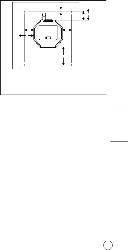
CLEARANCE TO COMBUSTIBLES
The following stated clearances represent the minimum distances between the stove and any other object. No objects should encroach into this space. This includes but is not limited to carpet, furniture, children, pets, clothing, fuel, or any other object. These clearances may only be reduced by means approved by the regulatory authority having jurisdiction.
|
REAR WALL |
|
|
E |
D B |
WALL |
D |
D |
A |
|
|
SIDE |
|
|
|
|
|
|
C |
|
|
FRONT OF HEATER |
|
NON-COMBUSTIBLE
FLOOR PROTECTION
Figure 1 Clearance to Combustibles
|
USA |
CANADA |
|
|
|
A |
13” (330 mm) |
13” (330 mm) |
|
|
|
B |
2” (51 mm) |
2” (51 mm) |
|
|
|
C |
18” (457 mm) |
18” (457 mm) |
|
|
|
D |
8” (203 mm) |
8” (203 mm) |
|
|
|
E |
3” (76 mm) |
3” (76 mm) |
|
|
|
FLOORING SPACE & CLEARANCES
When installed on a combustible floor, noncombustible floor protection is required to:
•Cover the area beneath the stove and extend at least 18 inches (457 mm) to the front
•Cover the area at least 8 inches (203 mm) beyond each side of the room heater.
•Cover the area under the exhaust venting and 2 inches (50.8 mm) beyond each side.
Additionally, the wood pellet fire stove shall be positioned such that:
•It has at least 13” (330 mm) of clearance from the each side to the nearest body.
•It has at least 2” (51 mm) of clearance from the rear to the nearest body.
•Vertical runs of vent pipe must be at least 3” (76 mm) from any wall.
Finally, the area which the wood pellet fire stove is installed shall have a floor-to-ceiling distance of at least
84” (2134 mm).
FLOORING MATERIAL
Floor protection must be all of the following:
•Listed to UL 1618.
•At least 0.5” (13 mm) thick
•Constructed of non-combustible material.
•Have either:
Thermal resistance value R of 1.19 |
(ft2)(hr)(0F) |
Btu |
(Btu) (inch)
Thermal conductivity value k of 0.84 (ft2)(hr)(0F)
For assistance evaluating the suitability of substitute materials, the following equivalences of specifications and example below have been provided.
|
|
thickness |
|
|
(Imperial or SI units) |
||||||
|
|
|
(Btu) (inch) |
|
|
W |
|||||
Thermal conductivity k = |
|
|
R |
( (ft2)(hr)(0F) or |
|
(m)(0K) |
) |
||||
|
|
1 |
|
|
(Btu) |
|
|
W |
|||
Thermal conductance C = |
|
R |
|
( |
(ft2)(hr)(0F) |
or |
(m2)(0K) |
) |
|||
Example: Required to protect floor with R value of 1.19
(ft2)(hr)(0F) Btu .
Evaluating merit of 2¼ inch (57 mm) thick brick with
thermal conductivity k = 4.16 on top of ¼ inch
(6.3 mm) thick mineral board that has C value of 2.3
(Btu) (ft2)(hr)(0F) .
Step 1. Calculate the R value of each floor material
|
|
thickness |
|
|
|
2.25 |
|
|
RBRICK = |
k |
= |
|
4.16 |
= 0.54 |
|||
|
|
|
||||||
|
|
1 |
|
|
|
1 |
|
|
RBOARD = |
C |
= |
2.3 |
= 0.434 |
||||
|
|
|||||||
Step 2. Add the equivalent R values for each floor material
RBRICK + RBOARD = 0.54 + 0.434 = 0.974
Step 3. This combined R value is insufficient and so more protection must be provided. For example, by using 2 layers of bricks:
RBRICK + RBRICK + RBOARD = 0.54 +0.54 + 0.434 = 1.514
Step 4. Because this combined R value is larger than the specification, this is a sufficient method for protecting the floor area underneath the stove.
Cleveland Iron Works Wood Pellet Fire Stove |
5 |
Operating Instructions and Owner’s Manual |
|
UNPACKING & ASSEMBLY
1.Remove heater from carton.
2.Remove all protective packaging applied to heater for shipment.
3.Check heater for any shipping damage. If any damage is found immediately contact the manufacturer at 800-251-0001.
 CAUTION: DAMAGED PARTS MAY
COMPROMISE SAFE OPERATION.
•DO NOT INSTALL INCOMPLETE COMPONENTS.
•DO NOT INSTALL SUBSTITUTE COMPONENTS.
•DO NOT INSTALL DAMAGED COMPONENTS.
4.Some components are packaged unattached from the stove in order to ensure their safety during shipping. Please find the protective packaging, likely inside the stove door, to proceed with assembly.
Main Power Cord
The main power cord attaches to the stove at the exposed socket in the rear of the stove. Once any necessary assembly of the display panel screen is complete (PSBF66W only) you may briefly plug your stove in make sure that it functions properly before proceeding with installation. Unplug the stove once you confirm that the display panel works.
 CAUTION: DO NOT LEAVE THE STOVE PLUGGED INTO ANY ELECTRICAL SUPPLY DURING ASSEMBLY OR INSTALLATION.
Firepot
With the stove unplugged from any power supply, the firepot should be inserted into the stove so that it is securely positioned and also the hot surface igniter should be able to make physical contact with pellets that would be held in the firepot. See figure 2 or 3.
Figure 2 PS60W and |
PS130W firepot |
Figure 3 PSBF66W |
firepot |
A cleaning kit is also packaged which facilitates safely cleaning the firepot perforations of debris.
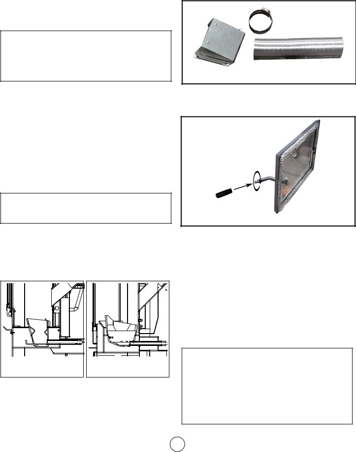
Air Intake Kit
Locate the air intake kit packaged with the stove. See Figure 4. Take measurements of your space and plan for the installation of horizontal venting to the outside
as may be required per recommendations in “FRESH AIR AND VENTILATION REQUIREMENTS 1” on page
7. Follow all ventilation requirements and guidelines specified in “INSTALLATION” on page 6.
Termination Cap
Hose Clamp
2” Flex Hose
Figure 4 Intake Kit
Additional Assembly PS60W, PS130W
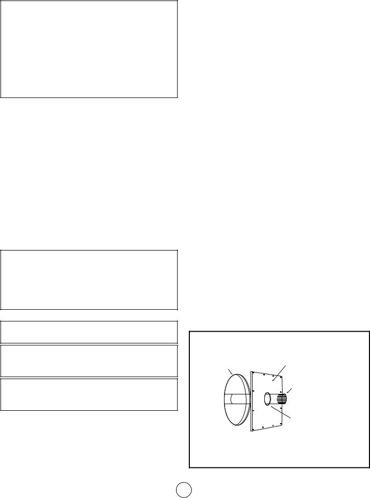
•The door handle: open the door, and screw the plastic grip onto the thread of the handle.
Figure 5 Door Handle
Additional Assembly PSBF66W
•The display panel: insert the display panel into the top and rear of the stove. Be sure that the display panel screen is facing towards the front of the stove. Secure the screen using two of the provided screws.
•The power cord for the display panel: this cord should be wrapped up near the top of the stove. Insert free end into the back of the display panel (see figure 16 on page 14). This wire should
already be connected to the stoves power board. This connection can be checked behind the access plate at the bottom and rear of stove .
INSTALLATION
 WARNING: WHEN THIS STOVE IS NOT PROPERLY INSTALLED, A HOUSE FIRE MAY RESULT. TO REDUCE THE RISK OF FIRE, FOLLOW THE INSTALLATION INSTRUCTIONS. CONTACT LOCAL BUILDING OR FIRE OFFICIALS ABOUT RESTRICTIONS AND INSTALLATION INSPECTION REQUIREMENTS IN YOUR AREA.
Cleveland Iron Works Wood Pellet Fire Stove |
6 |
Operating Instructions and Owner’s Manual |
|

 CAUTION: ANY DEVIATION OR ALTERATION FROM THESE INSTALLATION INSTRUCTIONS MAY RESULT IN DAMAGE TO YOU, THE STOVE, YOUR CHIMNEY, AND YOUR HOME. YOUR WARRANTY MAY BECOME VOID. READ AND FOLLOW ALL INSTRUCTIONS. Contact Cleveland Iron Works with any comments, concerns, or questions.
 CAUTION: CONTACT LOCAL BUILDING OR FIRE OFFICIALS ABOUT RESTRICTIONS AND INSTALLATION INSPECTION REQUIREMENTS IN YOUR AREA.
CONTACT INFORMATION
If you have any questions regarding ventilation options of your stove, contact either:
The manufacturer Cleveland Ironworks Company at
1-800-251-0001 • CLEVELAND-IRONWORKS.COM Our office hours are 8:00 AM – 5:00 PM, EST, Monday through Friday.
The National Fire Protection Association (NFPA) and request a copy of the latest editions of NFPA Standard 211. The mailing address of the NFPA is Batterymarch Park, Quincy, MA 02269
PLANNING
Make sure that you have selected the correct stove for your heating requirements by checking the specifications table on page 3.
Take measurements of your space and plan for your chimney system as detailed in the following instructions.
This stove may be installed for use in a mobile home. In addition to the following instructions, review and adhere to the mandatory requirements on page 10.
ELECTRICAL CONSIDERATIONS
The rear of the stove will need to be within power cord distance, which is roughly 80 inches (203 cm), of an electrical outlet. Lay the power cord out such that it will not come into contact with the stove’s surface.
TOOLS REQUIRED (NOT SUPPLIED)
• Safety Glasses |
• Reciprocating saw |
• Gloves |
• High Temperature |
• Tape Measure |
Silicone |
• Phillips Screwdriver or |
• A friend (the stove is |
comparable electric |
heavy, do not attempt |
screw driver & drill bit. |
to move the stove |
• Stud Finder |
without assistance) |
• Plumb bob |
|
PARTS & MATERIALS REQUIRED (NOT SUPPLIED)
•Floor Protection (see “FLOORING SPACE” and “FLOORING MATERIAL” on page 5)
•Manufactured venting of 3” (80 mm) diameter, of type “L” or “PL” which is listed to UL 641, ULC S609 (Standard for 650°C Factory-Built Chimneys), or ULC/ORD C441. Install per chimney manufacturer’s instructions.
FRESH AIR AND VENTILATION REQUIREMENTS
When deciding the location of the stove ensure that the space will always have a source of fresh air available. Failure to do so may result in air starvation of other fuel burning appliances and the possible development of hazardous conditions.
Provision for outside combustion air may be necessary to ensure that fuel-burning appliances do not discharge products of combustion into the house. Guidelines to determine the need for additional combustion air may not be adequate for every situation. If in doubt, it is advisable to provide additional air. Outside combustion air may be required if these or other indications suggest that infiltration air is inadequate:
•The wood pellet fired stove does not draw steadily, experiences smoke roll-out, burns poorly, or backdrafts, whether or not there is combustion present.
•Existing fuel-fired equipment in the house, such as fireplaces or other heating appliances, smell, do not operate properly, suffer smoke roll-out when opened, or back-draft, whether or not there is combustion present.
•Any of the above symtoms are alleviated by opening a window slightly on a calm (windless) day.
•The house is equipped with a well-sealed vapour barrier and tight fitting windows and/or has any powered devices which exhaust house air.
•There is excessive condensation on windows in the winter.
•A ventilation system is installed in the house. Additional combustion air may be directly provided from the outdoors to the wood pellet fired stove by using the included air intake kit to connect to the inlet at the bottom and rear of the stove. Any such installation must satisfy Clause 4 of CSA Standard B365.
 CAUTION: NEVER DRAW OUTSIDE
COMBUSTION AIR FROM:
•A WALL, FLOOR OR CEILING CAVITY.
•AN ENCLOSED SPACE SUCH AS AN ATTIC, GARAGE OR CRAWL SPACE.
 CAUTION: IF USING AN AIR INTAKE CONNECTION THEN THE STOVE MUST BE INSTALLED SUCH THAT IT IS ATTACHED TO THE STRUCTURE.
Cleveland Iron Works Wood Pellet Fire Stove |
7 |
Operating Instructions and Owner’s Manual |
|
CONNECTOR REQUIREMENTS AND ASSEMBLY
 CAUTION: A CHIMNEY CONNECTOR SHALL NOT PASS THROUGH AN ATTIC OR ROOF SPACE, CLOSET OR SIMILAR CONCEALED SPACE, OR A FLOOR, OR CEILING. WHERE PASSAGE THROUGH A WALL, OR PARTITION OF COMBUSTIBLE CONSTRUCTION IS DESIRED, THE INSTALLATION SHALL CONFORM TO CAN/CSA-B365, INSTALLATION CODE FOR SOLID-FUEL-BURNING APPLIANCES AND EQUIPMENT
Any connector pipes or elbows should be installed with the crimped end on the stove end of the path (not the chimney cap end) and should be secured with three evenly spaced sheet metal screws.
Connectors, elbows, and chimneys should be type ‘L’ or ‘PL’ and have a 80mm, or 3 inch diameter, diameter as the flue system is based on negative pressure in the combustion chamber and a slight overpressure on the flue gas outlet. It is therefore important that the flue gas connection is fitted correctly and is airtight.
It is recommended that connectors, elbows, and chimneys be at least 24 gauge, double walled, type B ventilation.
Note that bends in the exhaust path restricts air flow, reducing performance and provides a collection point for ash deposits requiring more frequent cleaning.
 CAUTION: THE JOINTS OF ANY AND ALL CONNECTIONS FOR ANY VENTILATION SYSTEMS (COMBUSTION EXHAUST AND OPTIONAL INLET AIR DUCT) MUST BE SEALED WITH HIGH TEMPERATURE SILICONE.
GENERAL VENTING REQUIREMENTS
 CAUTION: DO NOT CONNECT TO ANY AIR DISTRIBUTION DUCT OR SYSTEM.
 CAUTION: DO NOT CONNECT THIS UNIT TO A CHIMNEY FLUE SERVING ANOTHER APPLIANCE.
 CAUTION: DO NOT INSTALL A FLUE DAMPER IN THE EXHAUST VENTING SYSTEM OF THIS WOOD PELLET FIRED STOVE.
This wood pellet fire stove must be connected to either of the following:
•Class A listed chimney complying with the requirements for Type HT chimneys in the Standard for Chimneys, Factory-Built, Residential Type and Building Heating Appliance, UL 103.
•A International Conference of Building Officials
(ICBO) standards for solid fuel Stoves code-
approved masonry chimney.
VENT TERMINATION
•Install exhaust vent at clearances specified by the vent manufacturer.
•Install exhaust vent terminations at clearances specified by the vent manufacturer.
•If using the air intake kit, ensure that there is at least 12 inches clearance between the exhaust vent termination and the intake air inlet.
•It is recommened to keep at least 12” (30.5 cm) of clearance between any vent termination and windows, doors, or outside corners.
•Use silicone to create an effective vapor barrier at the location where the chimney or other component penetrates to the exterior of the structure.
•For additional requirements check local codes.
Any vertically terminated chimney systems must meet the following minimum requirements:
•Must be at least 15 feet (4.6 m) tall, measured from the top of the stove to the tip of the chimney cap.
•Must be at least 3 feet above the roof, measured from the highest point of contact with the roof and the tip of the chimney cap.
•Must be at least 2 feet (61 cm) above the highest point of the slope of the roof within 10 feet (305 cm) horizontally.
Any horizontally terminated chimney systems must meet the following minimum requirements:
•Must have at least 12” (30.5 cm) clearance above grade, veranda porch, deck or balcony (Including vegetation and mulch).
PASSING THROUGH A WALL
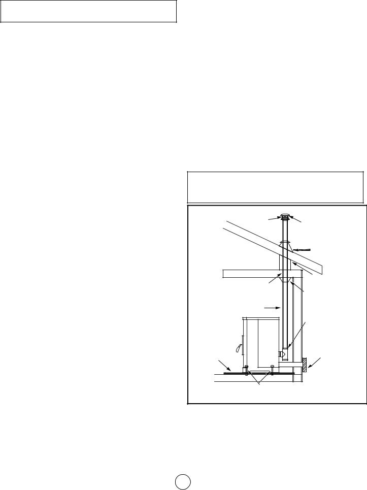
Where passage through a wall or partition of combustible construction is desired, the installation shall conform to chimney manufacturer’s instructions.
NOTE: In Canada, installation must conform to CAN/CSA-B365 when passing through combustible construction, illustrated in figure 6 .
Hole with a minimum |
Non-combustible cover, one |
|
side only. If two covers are |
||
clearance of 18” (450 |
||
used, each must be mounted |
||
mm) between |
||
on non-combustible spacers |
||
connector and wall |
||
at least 7/8” (21mm) away |
||
|
from the wall. |
|
|
Stove connector pipe |
|
|
1” (25mm) clearance |
Figure 6
ONLY APPROVED CANADIAN WALL PASS THROUGH
Cleveland Iron Works Wood Pellet Fire Stove |
8 |
Operating Instructions and Owner’s Manual |
|
NFPA 211 (US ONLY) APPROVED WALL PASS THROUGH TECHNIQUES
Figure 7 (US ONLY)
Brick Masonry: Minimum 3.5 inch (89 mm)thick brick masonry all framed into combustible wall with a minimum of 12 inch (305 mm) brick separation from clay liner to combustibles. The fireclay liner shall run from outer surface of brick wall to, but not beyond, the inner surface of chimney flue liner and shall be firmly cemented in place.
Figure 8 (US ONLY)
Insulated Sleeve: Solid-insulated, listed factory-built chimney length of the same inside diameter as the chimney connector and having 1 inch (25.4 cm) or more of insulation with a minimum 9 inch (229 mm) air space between the outer wall of the chimney length and combustibles.
Figure 9 (US ONLY)
Ventilated Thimble: Sheet steel chimney connector, minimum 24 gauge in thickness, with a ventilated thimble, minimum 24 gauge in thickness, having two 1 inch (25.4 mm) air channels, separated from combustibles by a minimum of 6 inches (152 mm) of glass fiber insulation. Opening shall be covered, and thimble supported with a sheet steel support, minimum 24 gauge in thickness.
Figure 10 (US ONLY)
Chimney Section Pass-through: Solid insulated, listed factory-built chimney length with an inside diameter 2 inches (51 mm) larger than the chimney connector and having 1 inch (25.4 mm) or more of insulation, serving as a pass-through for a single wall sheet steel chimney connector of minimum 24 gauge thickness, with a minimum 2 inches (51 mm) of air space between the outer wall of chimney section and combustibles. Minimum length of chimney section shall be 12 inches (305 mm) chimney section spaced 1 inch (25.4 mm) away from connector using sheet
steel support plates on both ends of chimney section. Opening shall be covered, and chimney section supported on both sides with sheet steel support securely fastened to wall surfaces of minimum 24 gauge thickness. Fasteners used to secure chimney section shall not penetrate chimney flue liner.
Cleveland Iron Works Wood Pellet Fire Stove |
9 |
Operating Instructions and Owner’s Manual |
|
ADDITIONAL MOBILE HOME REQUIREMENTS
 WARNING: DO NOT INSTALL IN SLEEPING ROOM.
PARTS & MATERIALS REQUIRED (NOT SUPPLIED)
•A 80mm diameter chimney which complies to UL 103, Standard for Factory-Built Chimneys for Residential Type and Building Heating Appliances.
•Ceiling thimble suitable for use in mobile home.
•Roof thimble suitable for use in mobile home.
•Spark arrestor suitable for use in mobile home.
•Roof flashing suitable for use in mobile home.
ADDITIONAL INSTALLATION REQUIREMENTS
•The chimney shall attach directly to the room heater and shall extend at least 3 feet (0.9 m) above the part of the roof through which it passes.
•The top of the chimney is to be at least 2 feet (0.6 m) above the highest required elevation of any part of the mobile home within 10 feet (3 m) of the chimney.
•All roof-chimney terminations shall be able to be readily removed at or below an elevation of 13½ feet
(4.1 m) above ground level and reinstalled without the use of special tools or instructions.
•The chimney assembly shall be provided with a mechanical securement means to secure the chimney to the ceiling support box.
•Chimney Guard Requirements:
—— When the chimney exits the mobile home at a location other than through the roof, and exits at a point 7 feet (2.1 m) or less above the ground level on which the mobile home is
positioned, a guard or method of enclosing the chimney shall be provided at the point of exit for a height up to 7 feet.
—— The chimney guard shall not have any openings large enough that a 3/4 inch diameter rod can enter.
—— The chimney guard shall not have any openings large enough that a 1/2 inch diameter rod can enter beyond 4 inches
•The stove must be on installed on a level surface which can support the weight of the stove.
•The stove must be bolted to the level surface so that it permanently secured and can not be moved, tipped, or have ventilation seals compromised.
•The stove must be provided a permanently ducted source of outside air to support combustion which meets the following requirements:
—— The duct must be made of metal exclusively, not other materials such as plastic.
—— The end of this duct must be equipped with a screen which prevents rodents from infiltrating.
—— The end of this duct must be kept free of leaves, snow, ice, or other debris that could restrict air supply when the appliance is in operation.
•The joints of any and all connections for both of ventilation systems (the inlet air and the combustion exhaust) must be sealed with high temperature silicone.
•The chimney must comply with all applicable codes and requirements of the authority having jurisdiction.
•The chimney must be removed for any mobile home transportation, and reinstalled abiding all requirements after transportation.
The flue system is based on negative pressure in the combustion chamber and a slight overpressure on the flue gas outlet. It is therefore important that the flue gas connection is fitted correctly and is airtight.
 CAUTION: THE STRUCTURAL INTEGRITY OF THE MOBILE HOME FLOOR, WALL, CEILING, AND ROOF MUST BE MAINTAINED.
UL 103 Chimney |
Mandatory Chimney Cap & |
|
Spark Arrestor |
|
Storm Collar & Roof |
|
Flashing per Local |
|
Mobile Home Building |
|
Codes |
Joist Shield |
|
/ Firestop |
|
|
Mobile Home |
UL 103 Pass-through system |
Thimble |
according to Manufacturer’s Parts |
|
& Instructions |
Chimney Support |
Double-wall UL 103 High |
|
Temperature Chimney Pipe |
|
|
Clean Out T |
|
Permanent, |
|
All-metal |
|
Combustion air |
|
Source with |
Floor |
Exterior Seal & |
Screen |
|
Protector |
|
Bolted to floor |
|
Figure 11 Mobile Home Vertical Chimney
Cleveland Iron Works Wood Pellet Fire Stove |
10 |
Operating Instructions and Owner’s Manual |
|
LINED MASONRY CHIMNEY INSTRUCTIONS & DIAGRAM
This stove is designed to be vented through a masonry chimney which conforms to local building codes, fire codes, and latest edition of NFPA 211 US or CAN/ CSA-B365.
1.If the connection piping from the stove to a masonry chimney is made through a combustible wall, consult a qualified mason or chimney dealer for consultation. To ensure safety, the installation should only be done by a qualified installer. The installation must conform to the regulations established by local fire codes and building codes
2.The chimney connection must not be obstructed by the chimney connector pipes, such as the figure 12 below illustrates.
Correct |
Wrong |
Wrong |
Figure 12 Connection Pipe & Chimney Connection |
||
3.If there is an opening at the base of the chimney it must be closed tightly.
MANUFACTURED CHIMNEY INSTRUCTIONS & DIAGRAM
 WARNING: DO NOT USE SINGLE-WALL CONNECTION PIPE AS A CHIMNEY.
This stove is designed to be used with either a UL 103HT (US)/ULC-S629 (CAN) listed manufactured chimney or an approved lined masonry chimney. Not all manufactured chimney are UL103 HT/ULC-S629 listed. Home centers, hardware stores, HVAC supply stores, and the Online websites of chimney manufacturers
will be able to provide stove pipe that is rated to these standards.
This listing indicates that the Chimney is rated for high temperatures up to 2100 °F (1149 °C)
Only use components that all come from the same manufacturer. Do not mix brands of components for the same ventilation system.
The following figures illustrate various methods and requirements of using a manufactured chimney and connection pipes to vent the stove.
Wall |
|
|
|
Termination |
|||
Thimble |
|||
Cap |
|||
|
|||
Double-wall UL 103 |
High Temperature |
Chimney Pipe |
|
6 in |
|
|
|
(152mm) |
||
WallThimble |
Minimum |
||
6 in |
|||
|
(152mm) |
||
|
Minimum |
||
|
|
|
|
|
|
|
|
|
|
|
|
|
|
|
|
|
|
|
|
|
|
|
|
|
|
|
|
|
|
|
|
|
|
|
|
|
|
|
|
|
|
|
Horizontal |
|
|
|
|
|
|
|
|
|
|
|
|
|
|
|
|
|
|
|
|
|
|
|
|
|
|
|
|
|
|
|
|
|
|
|
|
|
|
|
|
|
|
|
|
Termination |
|
Floor Protector Clean Out T |
|||||||
|
Cap |
|||||||
Figure 13 Manufactured Chimney through Wall
UL 103 Chimney |
Mandatory Chimney Cap & |
|
|
|
Spark Arrestor |
|
Storm Collar & Roof |
|
Flashing per Local |
|
Mobile Home Building |
|
Codes |
Joist Shield |
|
/ Firestop |
|
|
Attic Insulation |
|
Shield |
Chimney Support |
|
Double-wall UL 103 High |
|
Temperature Chimney Pipe |
|
|
Clean Out T |
Floor |
|
Protector |
|
Bolted to floor |
|
Figure 14 Manufactured Chimney through Attic
Cleveland Iron Works Wood Pellet Fire Stove |
11 |
Operating Instructions and Owner’s Manual |
|
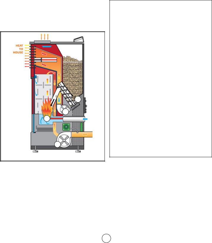
OPERATION
THEORY OF OPERATION
1.Combustion occurs in the fire pot, supported by air introduced to and under the fire pot. Note that some air blows in from the top of the combustion chamber; this helps keep ash and debris from accumulating on the door.
2.The exhaust blower draws combustion products from the stove and directs it out user-installed venting.
3.The auger transfers pellets from the hopper to the fire pot to sustain the fire.
4.A convection blower propagates air along the outside of the fire box, circulating warm and clean air into the room.
3
4
1
2
Figure 15 Stove Operation Process
APPROVED FUEL:
Do not use less than PFI premium-grade pellets. Use 100% natural wood pellets, untreated and without bonding agents added (max bark porportion of 5%) are the only fuel approved for use with this pellet stove. For best results see the specifications below:
•Calorific Value of 5.3 kWh/kg
•Density of 700 kg/m3
•The pellets should be low ash (less than 1 % ash)
•The pellets should be less then 30mm long, with a diameter between 5 and 6.5 mm.
•Do not use the pellet sediment & debris at the
bottom of the pellet container.
•Store pellets in sacks, made of environmentally neutral or biologically degradable plastic or from paper (2-3 layers / similar to cement packaging).
Use of wood pellets that do not meet these specifications may result in ignition difficulty, accelerated creosote or flyash build up, incomplete combustion, low heat yield, and blackening of the glass in the door.
 CAUTION: DO NOT USE CHEMICALS OR FLUIDS TO START THE FIRE.
 CAUTION: DO NOT BURN GARBAGE OR FLAMMABLE FLUIDS SUCH AS GASOLINE, NAPHTHA OR ENGINE OIL.
 CAUTION: NEVER ATTEMPT TO USE ANY OF THE FOLLOWING MATERIALS AS FUEL:
•Paper products, cardboard, or particleboard;
•Garbage;
•Animal remains or manure;
•Lawn clippings or yard waste;
•Waste petroleum products;
•Coal;
•Construction or demolition debris;
•Railroad ties or pressure-treated wood;
•Materials containing
——asbestos
——plastic
——rubber (including tires)
•Petroleum products such as
——paints
——paint thinners
——asphalt products
BURNING THESE MATERIALS MAY RESULT IN RELEASE OF TOXIC FUMES OR RENDER THE HEATER INEFFECTIVE AND CAUSE SMOKE
Do not store wood pellet fuel or other fire starting materials on floor protector, underneath stovepipe, or anywhere within minimum clearances from combustible surfaces specified on page 5.
Wood pellet fuel should be stored in a dry, well ventilated area.
Cleveland Iron Works Wood Pellet Fire Stove |
12 |
Operating Instructions and Owner’s Manual |
|

OPERATING PRECAUTIONS
 WARNING: HOT WHILE IN OPERATION. DO NOT TOUCH THE STOVE. KEEP CHILDREN, CLOTHING AND FURNITURE AWAY. CONTACT MAY CAUSE SKIN BURNS.
 CAUTION: ENSURE THAT THE FIREPOT AND THE PAN UNDERNEATH ARE CLEAN AND IN THE PROPER OPERATING POSITION BEFORE USING THE STOVE.
 WARNING: NEVER USE GASOLINE, GASOLINE-TYPE LANTERN FUEL, KEROSENE, CHARCOAL LIGHTER FLUID, OR SIMILAR
LIQUIDS TO START OR ‘FRESHEN UP’ A FIRE
IN THIS HEATER. KEEP ALL SUCH LIQUIDS WELL AWAY FROM THE HEATER WHILE IT IS IN USE.
PAINT CURING
To allow the paint to bond durably to the stove, start by running the stove on P1 Maximum Power for at least 30 minutes. Provide cross ventilation to eliminate odors or smoke cause by this curing process.
OPERATING PROCEDURE: TURN ON STOVE
NOTE: If the display screen indicates that the stove is “Switching Off” the stove can not be interrupted. The Display Message will
highlight to indicate that the state will not be changed. Only once the “Switching Off” cycle has finished and the exchanger has cooled can the stove be turned back on again.
1.Make sure that seals on the ash drawer and door are in good condition. If the stove has never been run before, add a handful of pellets directly to the firepot. Close the ash drawer and doors securely, and check that all side panels are all properly installed.
NOTE: DO NOT USE GRATES, IRONS, OR ANY OTHER METHODS OF SUPPORTING WOOD PELLET FUEL. ONLY THE FIREPOT SPECIFIC TO YOUR MODEL OF STOVE MAY BE USED.
2.Open the hopper. Ensure that there are a sufficient number of pellets to satisfy your heating requirements. Close the hopper.
3.Depress the power button  for 3 seconds. The stove will begin to automatically progress through the following stages:
•Cleaning Cycle: The firepot draws dust, ash, &
Cleveland Iron Works Wood Pellet Fire Stove
remenants out.
•Feeding Cycle: Pellets will be transported from the Pellet Hopper into the fire pot by the auger. This can take 5 to 15 minutes depending on the model of stove.
•Lighting Cycle: The electrically powered hot surface igniter will power on for 8 minutes and begin combustion of the pellets in the firepot. The heater will remain in the Lighting Cycle until the exhaust smoke reaches a designated temperature.
•Stabilization Cycle: The heater adjusts to fine tune the stove output to the desired temperature. This can take a few minutes
4.The stove has been successfully turned on.
OPERATING PROCEDURE: TURN OFF STOVE
NOTE: THE STOVE MAY BE TURNED OFF, REGARDLESS OF WHAT CYCLE THE DISPLAY SCREEN INDICATES THAT THE STOVE IS IN, BY DEPRESSING AND HOLDING THE POWER BUTTON FOR TWO SECONDS. ONCE THE DISPLAY SCREEN INDICATES THAT THE STOVE IS IN THE STABILIZATION CYCLE PRESS THE POWER BUTTON AGAIN. THE STOVE WILL ENTER THE COOLING CYCLE, STATED ON THE DISPLAY SCREEN.
 CAUTION: AFTER THE COOLING CYCLE THE STOVE AUTOMATICALLY BEGINS THE PROCESS OF CYCLING ON.
1.Depress the power button for 3 seconds. The stove will begin to automatically progress through the following stages:
•Switching Off: Any remaining fuel in the firepot will continue to burn and produce heat and flame. After 5 to 8 minutes the firepot ought to be devoid of fuel. The heat exchanger may then begin to cool off.
•Goodbye: The final message from the display screen to designate that the stove has cooled.
2.The stove has been successfully turned off.
OPERATION WITH AN ELECTRICAL GENERATOR
This stove is designed to have the option of being powered by an electrical generator, though not all electrical generator’s may be compatible with this stove. Consult the information regarding your generator’s electrical regulator and make sure that
it meets the electrical requirements of this stove, as stated on page 3.
MINIMIZING CREOSOTE FORMATION
13 Operating Instructions and Owner’s Manual
See “MAINTENANCE” on page 17 for an explanation of Creosote formation and removal. To slow the build up of creosote within your chimney burn only the recommended fuel, see page 12.
DISPOSAL OF ASHES
 CAUTION: EMBERS MAY BE OBSCURED BY ASH. HANDLE ASH WITH TOOLS SUFFICIENT FOR FIRE TENDING, NEVER DIRECTLY WITH YOUR HANDS. WEAR FIRE RETARDANT CLOTHING AND PROTECTIVE EYEWARE.
Ashes should be placed in a metal container with a tight fitting lid.
1.Other waste shall not be placed in ash containers.
2.The closed container of ashes should be placed on a noncombustible floor or on the ground, well away from all combustible materials, pending final disposal.
3.Wood mineral residue (approximately 1-2%) remains in the ash and is an excellent natural fertilizer product for all garden plants. Before disposing ashes of by burial in soil or otherwise locally dispersed, they should be retained in the closed container until all any and all cinders have thoroughly cooled and should also be “quenched” with water.
Remote Button Functionality:
The buttons on the remote controller affect the stoves operation in the same way that the mounted button do, explained in v:
Remote Controller |
Mounted Button |
||
|
Button |
Counterpart |
|
|
|
|
|
|
|
|
|
Auto
Note: There are no lights or display screen on the remote controller that can indicate to you that the button presses are being received by the stove. In order to remotely control the stove but also monitor its settings, try installing the Smart Stove app.
Cleveland Iron Works Wood Pellet Fire Stove
SMART STOVE WIFI CONNECTION
This stove can be monitored, controlled, and programmed by using the smart stove app by NHHATC which is available for iOS or android device through the app store.
Step 1. Download the Smart Stove app by NHHATC.
Step 2. Open the Smart Stove app. The app opens, by default, to the “Devices” tab which is indicated at the bottom of the screen.
Step 3. If you have no other wifi enabled devices already added to this app there will be a large button in the center of the screen which you can select. Otherwise, select the + symbol in the top right of the screen.
Step 4. Make sure that your device is connected to the wifi network which you want the stove to be connected to.
Step 5. Make sure that the wood pellet fire stove is plugged into an electrical outlet and can be powered on.
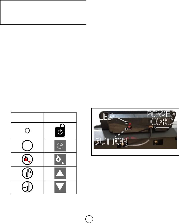
Step 6. Follow the directions on the screen by pressing and holding the connection button for 3 seconds on the rear of the display panel
as illustrated in the figure below. Once you observe the desired blinking pattern on the indicator light, press the confirmation button at the bottom of the screen.
LED |
POWER |
|
CORD |
BUTTON
Figure 16 Display Panel Back
Step 7. Enter the password for the wifi network so that the stove can connect to the wifi network.
Step 8. The stove will begin pairing with the device running the application through the wifi network. This process may take a few minutes.
Step 9. If the connection between the stove and device fails, return to step 6. Rather than following the directions currently on the screen, select
“AP Mode” in the top righthand corner. Then proceed with steps 7 and 8.
Step 10. After the device and stove are paired, you will be able to see the pellet stove as a
14 connection option on the “Devices” tab at the
Operating Instructions and Owner’s Manual

bottom of the app screen.
Step 11. On your device, go to your device’s wifi settings which will now include the stove as an option. Select the stove as your wifi connection.
Step 12. Open the Smart Stove phone app again.
Step 13. You may now select this stove from this added devices list in order to monitor, control, and program the stoves operation.
WIFI CONTROLS
Once connected to the stove (See step 11 of Wifi Connection) you an remotely monitor and adjust the operation of the stove. See below for explanation:
•Device Name: it is possible to rename the stove, so that if you have multiple stoves set up for operation you can more easily differentiate between while using the smart stove application.
•Device Sharing: it is possible to share connection to the stove with other devices via SMS or email.
•Eco Mode: There are two ECO settings which can be selected which will conserve wood pellets while maintaining the desired temperature. Pressing the ECO button will allow you to toggle whether a specific eco setting is enabled, or to turn off the feature entirely.
•ECO 1: The stove shuts off when the desired temperature has been reached. The stove will turn back once the room cools to a factory set temperature.
•ECO 2: The stove turns to minimum power preset P4 when the desired temperature has been reached. The stove will turn on to higher power settings once the room cools to a factory set temperature.
•Preset configurations: There are four selectable configurations which adjust the speeds of the combustion fan and the room air circulation fan. Pressing the preset configuration button will allow you to toggle whether a specific preset configuration is enabled, or to turn off the feature entirely.
•P1 [Maximum Power] Settings
•P2 [Medium Power] Settings
•P3 [Low Power] Settings
•P4 [Minimum Power] Settings
Device
Select
Screen
Stove
setting
Current room temperature
Eco Setting
Preset  configurations
Figure 17 Wifi Controls
Device Name and
Device Sharing
settings
Decrease stove output
 Increase stove output
 Program and set stove scheduled operation
Cleveland Iron Works Wood Pellet Fire Stove |
15 |
Operating Instructions and Owner’s Manual |
|
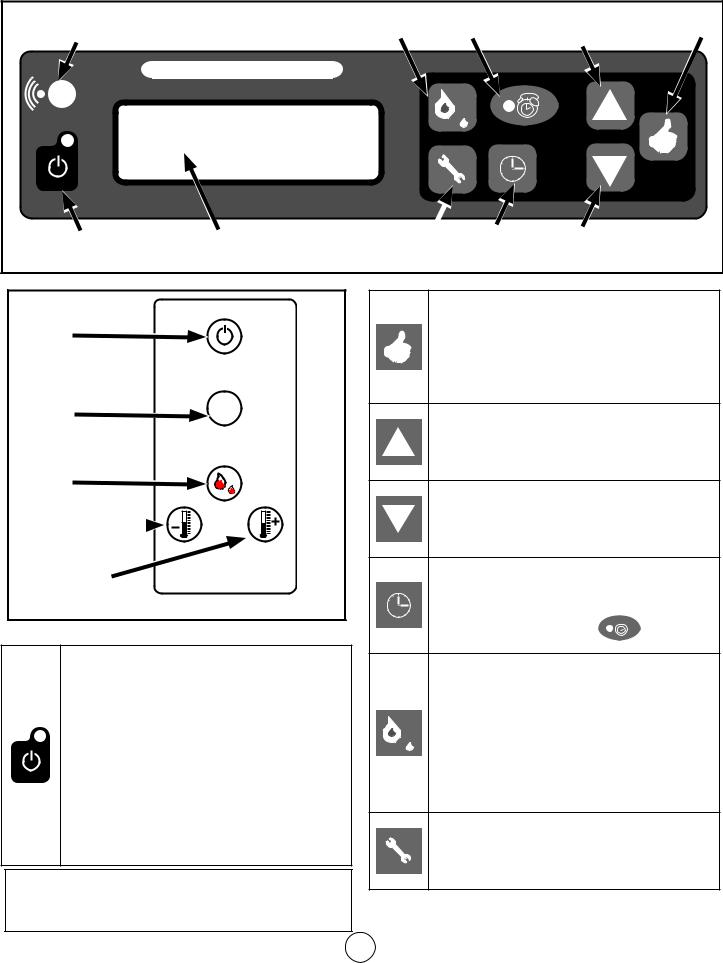
PS60W, PS130W, AND PSBF66W MULTI FUNCTION CONTROLS
Wireless Connection |
Rate Select |
Manual / Automatic |
|
Confirm |
||
Notification Light |
Notification Light |
Up Selector |
||||
|
|
|
|
|
|
|
MULTI FUNCTION DISPLAY |
|
|
|
|
|
|
Power |
Display Screen |
Settings |
Time |
Down Selector |
||
Figure 18a Mounted Multi Function Controls Panel |
|
|
|
|
|
|
Power |
|
Manual / |
|
Automatic |
|
Toggle |
Auto |
Rate Select
Temperature
Decrease 
Temperature
Increase
Figure 18b Remote Controller
Mounted Button Functionality: Normal Operation
•The light illuminates when the stove is plugged into an electrical supply.
•Press the power button to turn the display on for the purpose of adjusting settings.
The screen will become dim after 10 seconds on inactivity.
• Press and hold the power button for 3 seconds to begin stove heating if the stove was off.
•Press and hold the power button for 3 seconds to begin stove shut off if the stove was on.
 CAUTION: The manufacturer has programmed preset rates to ensure proper operation. It is not advised to reprogram rate settings.
Press to cycle between temperature reports (in Fahrenheit) display in the top right of the multi function display screen:
•##(R): Room temperature
•##(S): Exhaust temperature
•##(P): Protection Temperature Sensor
Press to increase the temperature which the stove is intended to heat the room to. This value is displayed in the top right of the multi function display screen as ##0F.
Press to decrease the temperature which the stove is intended to heat the room to. This value is displayed in the top right of the multi function display screen as ##0F.
Press to toggle the stove between manual control and programmed control. If the stove is in the program controlled setting then the notification light 


 will be illuminated.
Pressing the rate select will toggle between four configurable heating presets. The currently set preset is available in the top middle of the multi function display screen as P#.
•P1: Maximum Power
•P2: Medium Power
•P3: Low Power
•P4: Minimum Power
•Press and hold the settings button for 2 seconds to enter the set up menu.
•Press the settings button at any time to exit the set up menu.
Cleveland Iron Works Wood Pellet Fire Stove |
16 |
Operating Instructions and Owner’s Manual |
|
MAINTENANCE
This wood heater needs periodic inspection and repair for proper operation. It is against federal regulations to operate this wood heater in a manner inconsistent with operating instructions in this manual.
 CAUTION: TURN OFF AND UNPLUG THE STOVE FROM ANY SOURCE OF ELECTRICAL POWER TO UNIT BEFORE PERFORMING ANY MAINTENANCE OR SERVICE OPERATIONS.
 CAUTION: ALLOW STOVE TO COOL DOWN BEFORE PERFORMING ANY MAINTENANCE OR SERVICE OPERATIONS.
 CAUTION: DURING ANY ASSEMBLY OR DISASSEMBLY, BE WARY TO NOT DROP ANY ITEMS (SCREWS, ETC.) INTO THE PELLET HOPPER. DEBRIS CAN JAM THE AUGER AND DAMAGE THE STOVE.
The frequency which your stove’s requires cleaning and maintenance depends on the fuel that you use. High moisture, ash, dust, and chips can more than double the necessary maintenance. Use only the tested and recommended wooden pellets fuel.
Clean the fire pot and fire pan every day, before using the stove and while the stove is cooled down, the stove is unplugged, and there are no embers. Use a vacuum cleaner to remove ash and debris from the fire pot, and then lift the fire pot to also clean the fire pan. It
is important that ash or debris does not block any air openings.
A general cleaning schedule is as follows:
•Fire Pot: After 10 bags of wood pellets, or every day. Whichever is more frequent.
•Ash Drawer: After 50 bags of wood pellets
•Passageways: After 100 bags of wood pellets
•Blower: After 100 bags of wood pellets
CLEANING: FIRE POT & PAN
 CAUTION: IF STOVE IS INTENDED TO OPERATE CONTINUOUSLY, IT MUST BE TURNED OFF TWICE WITHIN EACH 24 HOUR PERIOD IN ORDER TO CLEAN THE FIRE POT AND FIRE PAN. ALWAYS ALLOW THE STOVE TO COOL DOWN AND ANY EMBERS TO EXTINGUISH BEFORE CLEANING THE FIRE POT AND FIRE PAN.
Make sure that you put the fire pot back onto the fire pan in the correct orientation, so that pellets can be added to the pot and successfully ignited for the next operation of the stove.
CLEANING: GLASS
 WARNING: DO NOT CLEAN GLASS WHEN HOT.
Though the circulation of air across the glass reduces acidic ash build up, cleaning the glass in the stove door is still required periodically. Cleaning is necessary to prevent glass from being weakened which may increase likelyhood of cracks. It is not acceptable to operate the stove with cracked or broken glass.
The best way to clean the door glass is using a damp cloth that has a smear of cool ash on it. For extra stubborn dirt, consult your local hardware store or stove specialist for a suitable cleaner.
 WARNING: DO NOT CLEAN GLASS WITH ABRASIVE CLEANERS OR BY ANY OTHER PROCESS WHICH MAY SCRATCH OR DAMAGE THE GLASS.
CLEANING: INLET AND OUTLET PASSAGEWAYS
The inlet and outlet passageways should be cleaned at least once a year. Burning high ash pellets may require that the passageways are cleaned more frequently.
Figure 19 Inlet Duct
Figure 20 Outlet Duct
Cleveland Iron Works Wood Pellet Fire Stove |
17 |
Operating Instructions and Owner’s Manual |
|
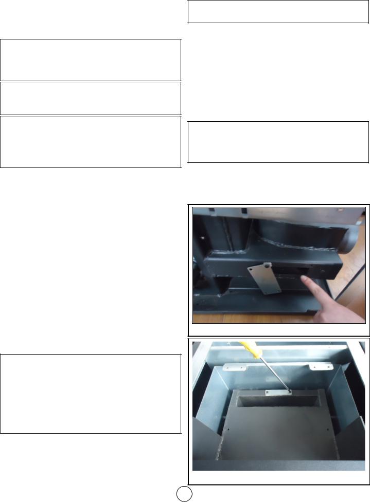
On each side of the stove there are two access covers that can be removed by removing the fastening screws. See Figures 22, 25 and 26. Turn off the stove, allow the stove to cool down, and unplug the stove before disassembly and cleaning. Insert a cleaning brush into the openings to loosen any ash build up and then use a vacuum cleaner to remove the loosened ash. Replace the covers and secure with the allen head screws.
There are two more openings to the inlet and outlet passageways which can be accessed by removing the ash drawer. Loosen the two 5/32” allen head screws shown in Figure 20. Rotate the covers to expose the opening. Use a cleaning brush to loosen any ash build up. Insert a cleaning brush into the openings to loosen any ash build up and then use a vacuum cleaner to remove the loosened ash. Rotate the covers back over the openings and secure with the allen screws.
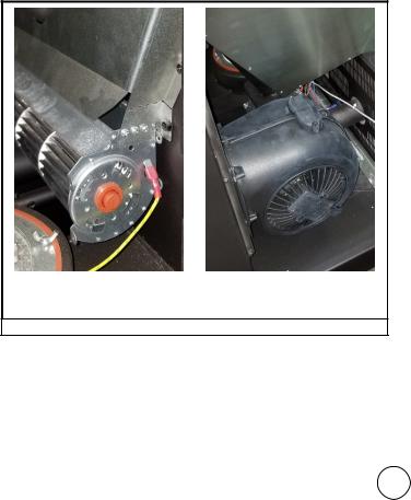
CLEANING: CONVECTION BLOWER
When facing the heater, the blower motor responsible for introducing air for heating and circulation to the room is located on the right hand side. Remove or open the side panel to obtain access. Clean the convection blower as required, before using the stove and while the stove is cooled down, the stove is unplugged,
and there are no embers. Take care to not damage the blower’s blades during cleaning. Use a vacuum to remove any dust accumulation of the blower’s blades or inside the blower duct.
PS130W PS60W, PSBF66W
Figure 22 Convection Blower Disassembly
CLEANING: EXHAUST VENT PIPE
Inspect the exhaust venting system at least once a year to determine if cleaning is necessary. During start up, shut down, and erroneous operation of the stove incomplete combustion can produce ash, soot, and
creosote. To clean the exhaust venting system insert an appropriate sized cleaning brush into the pipe to loosen and remove any ash or debris build up. Build up of debris and ash can restrict the flow of gases which will affect stove performance, and failure to remove creosote may result in a dangerous chimney fire.
FLYASH - FORMATION AND NEED FOR REMOVAL
The products of combustion will contain small particles of flyash. The flyash will collect in the exhaust venting system and restrict the flow of the flue gases. Incomplete combustion, such as occurs during startup, shutdown, or incorrect operation of the room heater will lead to some soot formation which will collect
in the exhaust venting system. The exhaust venting system should be inspected at least once every year to determine if cleaning is necessary. Use the appropriate sized chimney brush to remove ash and buildup from the venting.
CREOSOTE - FORMATION AND NEED FOR REMOVAL
Failure to remove creosote may result in a dangerous chimney fire.
When wood pellets burn at a low temperature they produce tar and other organic vapors, which combine with expelled moisture to form creosote. The creosote vapors condense in the relatively cool chimney flue of allow-temperature fire. As a result, creosote residue accumulates on the flue lining. When ignited this creosote makes an extremely hot fire. The chimney connector and chimney should be inspected at least once every few months during the heating season
to determine if a creosote buildup has occurred. If a significant layer of creosote has accumulated (eighth of an inch, 3 mm, or more) it should be removed to reduce the risk of a chimney fire. Use the appropriate sized chimney brush to remove ash and buildup from the venting.
Be aware that the hotter the fire the less creosote is deposited, and weekly cleaning may be necessary in mild weather even though monthly cleaning may be enough in the coldest months. Contact your local municipal or provincial fire authority for information on how to handle a chimney fire. Have a clearly understood plan to handle a chimney fire.
REPLACING: GLASS
Replacing the door glass is only permitted by replacing the entire door assembly provided by the manufacturer. See pages 27 through 29.
Cleveland Iron Works Wood Pellet Fire Stove |
18 |
Operating Instructions and Owner’s Manual |
|
 Loading...