

Cleveland MKDL-100-CC Installation Manual
Operators Manual
Cleveland
™
Installation, Operation & Service
Direct Steam Mixer Kettles
FOR UNITS BUILT AFTER JULY 2010
MODELS:
(T) MKDL-40-T (-CC)
(T) MKDL-60-T (-CC)
(T) MKDL-80-T (-CC))
(T) MKDL-100-T (-CC)
(T) MKDL-125-T (-CC)
(T) MKDL-150-T (-CC)
1333 East 179th St., Cleveland, Ohio, U.S.A. 44110
Ph: 216.481.4900 Fx: 216.481.3782
www.clevelandrange.com
For a complete Service Manual
refer to www.clevelandrange.com
SE95018 Rev. 6
February 2011
Shut off power at main
fuse disconnect prior
to servicing.
Ensure kettle is at room
temperature and pressure
gauge is showing zero or less
prior to removing any fittings.
Inspect unit daily for
proper operation.
0
Do not fill kettle above
recommended level
marked on outside of kettle.
Surfaces may be
extremely hot! Use
protective equipment.
Keep
appliance
and area
free and
clear of
combustibles.
Unit exhaust
contains carbon
monoxide.
Operate only
under a properly
functioning hood
with adequate
makeup air.
Stand clear of product
discharge path when
discharging hot product.
Wear protective equipment
when discharging hot product.
Do not lean on or place
objects on kettle lip.
Do not
attempt to
operate this
appliance
during a
power
failure.
Keep clear of pressure
relief discharge.
Keep hands away from
moving parts and pinch points.
For your safety
SERVICING
IMPORTANT
CAUTION
DANGER
GAS APPLIANCES
INSTALLATION
12"
6
"
B
A
C
WALL
18" CLEARANCE REQUIRED FOR SERVICE
DRAW-OFF
VALVE
12"
GENERAL
Installation of the kettle must be accomplished by
qualified installation personnel working to all applicable
local and national codes. Improper installation of
product could cause injury or damage.
This unit is built to comply with applicable standards for
manufacturers. Included among those approval
agencies are: UL, NSF, ASME/Ntl.Bd., CSA, ETL, CE,
and others. Many local codes exist, and it is the
responsibility of the owner/installer to comply with these
codes.
INSPECTION
Before uncrating, visually inspect the unit for evidence
of damage during shipping. If damage is noticed, do
not unpack the unit, follow shipping damage
instructions.
SHIPPING DAMAGE
INSTRUCTIONS
If shipping damage to the unit is discovered or
suspected, observe the following guidelines in
preparing a shipping damage claim.
1. Write down a description of the damage or the
reason for suspecting damage as soon as it is
discovered. This will help in filling out the claim
forms later. If possible, take a polaroid picture.
2. As soon as damage is discovered or
suspected, notify the carrier that delivered the
shipment.
3. Arrange for the carrier's representative to
examine the damage.
4. Fill out all carrier claims forms and have the
examining carrier sign and date each form.
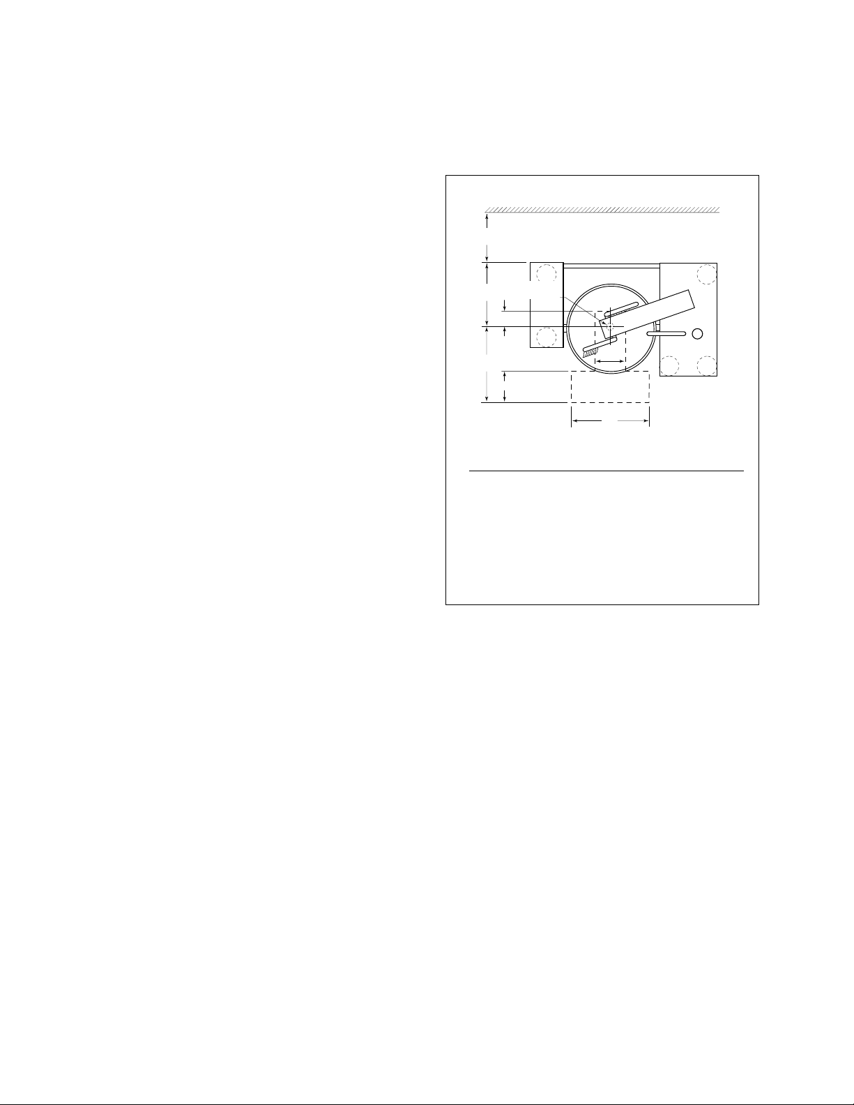
RECOMMENDED FLOOR
DRAIN LOCATION
ABC
(T) MKDL-40-T(-CC) 22 1/8" 51" 31"
(T) MKDL-60-T(-CC) 22 1/8" 53" 31"
(T) MKDL-80-T(-CC) 22 1/8" 58" 31"
(T) MKDL-100-T(-CC) 21 3/4" 61" 31"
(T) MKDL-125-T(-CC) 21 3/4" 65" 31"
(T) MKDL-150-T(-CC) 21 3/4" 68" 31"
Recommended Floor Drain Location
CLEARANCE REQUIREMENTS
This unit must be installed in accordance with the
clearances shown on the rating label which is adhered
to the unit.
FOR YOUR SAFETY. Keep the appliance area free and
clear of combustible materials.
MOVING UNIT
S
him as
required
to make
level with
center
console
(front
and back)
4"x4" or larger
(front and back)
Forklift tongs
Skid
Flanged feet
Jack
B
A
C
D
B
A
C
D
C
C
C
C
1. While still on skid, move unit as close to final
installation position as possible.
2. Prepare unit for lifting as shown in diagram.
3. Lift gently with a forklift or jacks and remove
skid.
Recommended Installation Procedure
4. Lower gently to ground and remove forklift
and blocking.
5. If unit has to be re-positioned, slide gently. Do
not twist or push one side of unit excessively
and cause binding on trunnions.
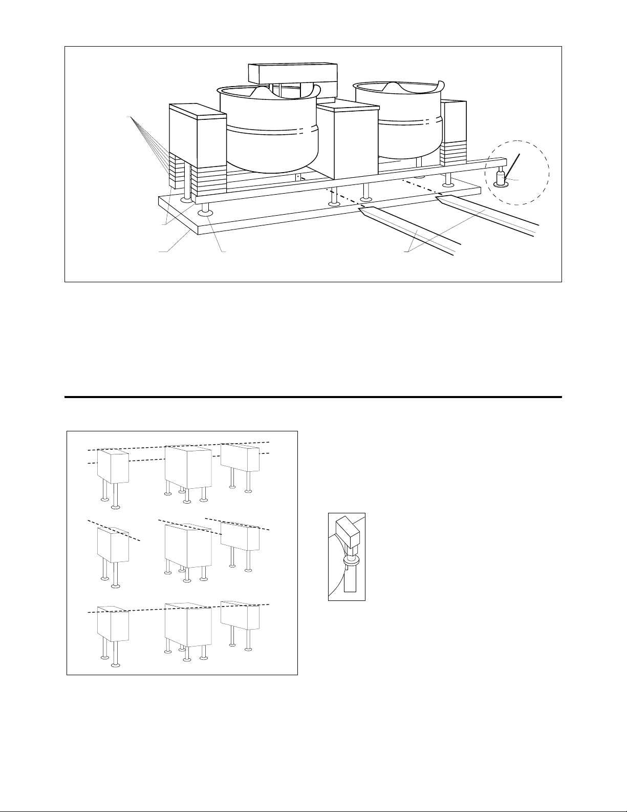
LEVELING
Recommended Leveling Procedure
Note: Instructions reflect a more complicated twin mixer kettle - process for single mixer kettles is the same.
1. With straight-edge, line the backs of the
consoles up with each other (dotted line A)
2.
Level and straight-edge backs of consoles
line B)
. Adjustments are made by turning flanges
on back feet only.
.
(dotted
3.
Level consoles individually from front to back
(dotted lines C). Adjustments are made by turning
flanges on front feet only.
4. Re-check that the back is level (dotted line B)
and then the front (dotted line D). Adjust if
necessary.
5. Check that mixer bridge is level and
guide pins lock smoothly without
binding. If not repeat steps 1 through 4.
Guide Pins
NOTE: See Operating Instructions before
operating unit.
6. Make electrical connections (see electrical
service connections) and test mixer bridge as
follows:
⇒ A/ Raise mixer bridge.
⇒ B/ Swing bridge out over center console.
⇒ C/ Swing bridge to the left as far as possible.

⇒ D/ Lower bridge.
⇒ E/ Bridge pins should enter pin hole on kettle
perfectly, If not return to step 1 and repeat
leveling steps.
⇒ F/ Raise bridge and swing to far right (for twin
mixers only).
⇒ G/ Repeat steps D and E (for twin mixers
only).
7. Once positioned and leveled, permanently
secure the kettle's flanged feet to the floor
using 5/16 inch stainless steel lag bolts and
floor anchors (supplied by the installer).
Secure each of the flanged feet with one bolt
in each hole.
8. Connect piping as described in the "PIPING
CONNECTION" section.
ELECTRICAL SERVICE
CONNECTIONS
Install in accordance with local codes and/or the
National Electric Code ANSI/NFPA No 70-1981 (USA)
or the Canadian Electric Code CSA Standard C22.1
(Canada). A separate fused disconnect switch must
be supplied and installed. The kettle must be
electrically grounded by the installer.
The electric supply must match the power
requirements specified on the kettle's rating plate.
The copper wiring must be adequate to carry the
required current at the rated voltage. Refer to the
specification sheet for electrical specifications.
1. Ensure main power is turned off before
connecting wires.
2. Remove the screws at the rear of the center
console cover, and remove the cover. A wiring
diagram is affixed to the underside of the
console cover.
3. Feed permanent copper wiring 18" through the
cut-out in the bottom of the console. Connect
wiring in junction box in the bottom of the
console.
4. Turn main power back on.
5. Check for correct rotation of electric motor
(access by removing top front cover on center
console). If rotation is incorrect, disconnect
main power and reverse any two of the three
live lines.
6. Replace the console cover and secure it with
screws.
COMPRESSED AIR CONNECTION
Mixer Kettles with an air activated discharge valve
require a minimum of 90 PSI to operate correctly.
If the unit is also supplying air to a Metering Filling
Station then a pressure of 100 PSI at a minimum volume
of 25 CFM is required.
The air supplied to the mixer should be clean and dry.
No oil should be added to the supply air. We
recommend the compressed air system be equipped
with a drier, filter, and automatic water dump on the air
compressor receiver tank. If the distance between the
tank and the unit is less than 100 feet then a minimum
line size of 3/4" is required. A distance of 100 to 300 feet
requires a minimum 1" line.
PIPING CONNECTIONS
1. All plumbing to and from the kettle should be
thoroughly cleaned and inspected for dirt and
debris before the final connections to the kettle
are made.
2. Connect all piping according to identification
tags on unit.
3. Piping between boiler and kettle should be
sloped and a drip condensate trap installed at
lowest point.
4. Insulating steam piping is recommended for
safety and higher efficiency.
5. To determine the correct steam supply pipe
size:
⇒ A/ Find the total steam requirement using the
first chart.
⇒ B/
Use the steam requirement total in the second
chart to find the correct pipe size.
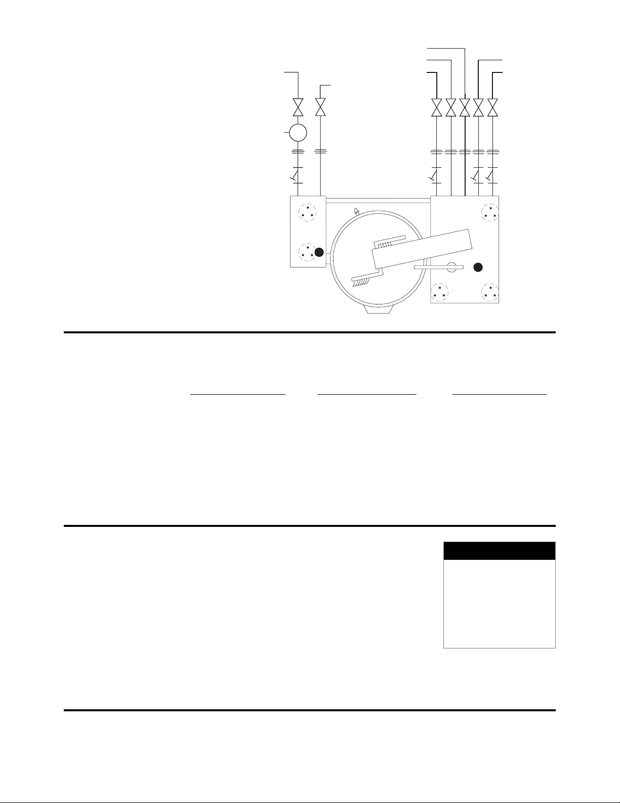
PIPING SCHEMATIC
HOT WATER
COLD WATER
CONDENSATE OUT
COOLING WATER IN
COOLING WATER OUT
STEAM IN
GLOBE VALVES
UNIONS
STRAINERS
DUMP VALVE TO DRAIN
PRESSURE
REDUCING
VAVLE
PVR
STEAM REQUIREMENTS FOR KETTLES
Kettle Cap. Kettle 25 psi Steam 265°F 40 psi Steam 287°F 80 psi Steam 302°F
U.S. Gal. Dia. Lbs./Hr. Hp./Hr. Lbs./Hr. Hp./Hr. Lbs./Hr. Hp./Hr.
40 26" 100 3 120 4 150 4.5
60 29.5" 150 4.5 190 5.5 230 7.0
80 33" 210 6.0 260 7.5 300 9.0
100 36" 260 7.5 320 9.5 390 11.0
125 40" 320 9.5 400 11.5 470 14.0
150 40" 390 11.0 480 14.0 570 17.0
Steam requirements are maximum per hour.
If more than one unit is on the same line then add the steam usage for each one to reach a total.
STEAM PIPE SIZING
Steam Required 200 Ft. 400 Ft. 600 Ft.
Required pipe length in feet/meters
Lbs./Kg. per hour 60 Meters 125 Meters 185 Meters
100/45 Kg. 3/4" 1" 1 1/4"
200/91 Kg. 1" 1 1/4" 1 1/2"
300/136 Kg. 1" 1 1/4" 1 1/2"
400/182 Kg. 1" 1 1/2" 1 3/4"
500/227 Kg. 1 1/4" 1 1/2" 1 3/4"
700/318 Kg. 1 1/2" 1 3/4" 2"
900/409 Kg. 1 1/2" 1 3/4" 2"
NOTES:
Pipe size in inches.
Less than 50 PSI (3.4
BAR) pressure, increase
pipe size by 1/4".
80 to 100 PSI (5.5 to 6.8
BAR), Decrease pipe
size by 1/4".

QUALITY ASSURANCE
CHECKLIST
Follow this list only after all other installation steps are completed.
Some steps require the use of equipment. Follow operating instructions.
The following will be performed before the unit is connected to utilities:
1. Visual Examine unit for scratches, dents, or other defects.
2. Visual Check flanged feet all have bolts holding them.
3. General Check all accessible wiring, mechanical and plumbing connections by hand for
secure, tight and satisfactory assembly. Remove all paper.
4. Level Check unit has been leveled and squared correctly.
The following will be performed with the unit connected to utilities:
5. Raise Bridge If bridge does not raise then check motor rotation. Bridge should not raise until
speed control is turned to minimum and then adjusted back up.
6. Swing Bridge Bridge when fully raised should swing without hitting any object, i.e. control
housing, kettle lip. Check that hydraulic hoses are not being pinched by stops
on swivel assembly.
7. Tilt Kettle Kettle tilts smoothly both down and back up. If power tilt, check that micro
switches are adjusted properly (kettle is level in upright position and drains fully
when tilted) and are not being crushed by gear.
8. Lower Bridge Raise bridge. Switch to mix. Turn speed control to zero to reset micro switch then
set speed control to number four. Check that unit does not begin to mix until
bridge has lowered part way into the kettle. Check that mixer bridge pin lowers
into pin hole correctly
9. Speed Control - Main agitator arm not rotating when set at minimum but will start to move slowly on
Main one. Speed control makes positive contact with micro switch.
10. Speed Control - Set main speed control to five. Adjust secondary control from
Secondary minimum to maximum. Look for considerable speed variance.
11. Water Faucets Turn on hot water faucet. Turn off and check for leaks in piping and drips from
faucet spout. Repeat above with cold water faucet.
12. Product Discharge Add water to kettle. Check for leaks from valve. Open and close valve a few times
Valve and check for leaks again.

OPTIONAL CONTROLS
Some units may not have the following items to test
13. Meter Complete this test using markings on mixer arm or a measuring strip if there are no
markings on the unit. Test the meter at the following values up to capacity (Should be
approx.±1/4"). During this test check that the (interrupt) switch stops the water flow
and the (continue/reset) when switched to "continue" resumes the flow without resetting
the meter.
GALLONS LITERS
5 20
20 80
40 160
80 320
100 400
When the (continue/reset) switch is turned to "reset" the displayed quantity on the
meter should be erased and the count begins at zero.
For the following test fill the kettle 3/4 full of water. Have the mixer rotating with the speed
control setting at three to five.
14. Heating Manual (Active/Bypass) switch in "Bypass" position. (Heat/Off/Cool) switch in "Heat"
position. Open manual steam valve, steam enters kettle and condensate escapes
from steam trap.
For units equipped with water cooling -
1./ Automatic drain opens and discharges water from jacket,
2./ Automatic drain closes when steam starts exiting,
3./ Condensate drain opens and discharges hot water.
Close manual steam valve and you should hear steam entering kettle slow to a
stop.
15. Cooling Manual Turn (Heat/Off/Cool) switch to "Off". Open manual steam valve. Turn
(Heat/Off/Cool) switch to "Cool". Cooling water enters kettle from large console and
exits from side console.
16. Heating Automatic (Heat/Off/Cool) switch in "Off" position. Open manual steam valve. Follow
operating instructions on label to set the temperature to 180°F/ 90°C. Turn
(Active/Bypass) switch to "Active", you should hear steam entering kettle and
condensate should escape steam trap.
For units equipped with water cooling -
1./ Automatic drain opens and discharges water from jacket,
2./ Automatic drain closes when steam starts exiting,
3./ Condensate drain opens and discharges hot water.
17. Chart Recorder a) Seal chart recorder on the inside all around to the panel with silicone.
b) Seal pipe penetration where cables enters panel from console with silicone all
around.
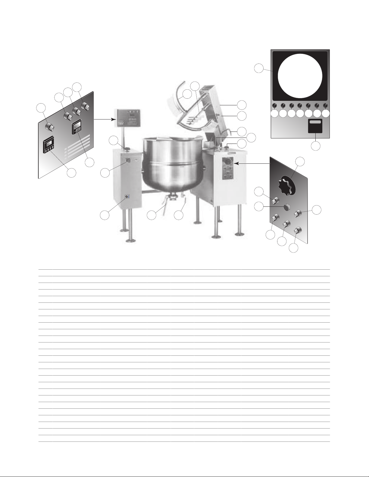
OPERATING INSTRUCTIONS
24 2526
18
15
21
19
20
16
17
23
22
Cl
e
v
e
l
a
nd
D
I
G
I
T
A
L
W
A
T
E
R
M
E
T
E
R
E
M
E
RG
E
N
C
Y
S
T
O
P
10
2
4
13
5
3
1
11
12
8
13
9
6
14
7
1 6 7 8 12 11 10
ITEM # DESCRIPTION FUNCTION
1 MAIN POWER SWITCH Power switch for unit.
2. MIX/LIFT SWITCH Sets hydraulics to mix or lift mode.
3. UP/DOWN SWITCH When unit is in lift mode, mixer bridge can be raised or lowered with this switch.
4. MIXER SPEED CONTROL Controls speed of agitators and mixer bridge lift.
5. EMERGENCY STOP BUTTON Stops hydraulic system (agitators and mixer bridge lift).
6. HEAT/COOL SWITCH Switches left hand kettle from heating to cooling.
7. HEAT/COOL SWITCH Switches right hand kettle from heating to cooling.
8. ACTIVE/BYPASS SWITCH Switch to activate or bypass (manual operation) the controller.
9. TEMPERATURE CONTROLLER Digital temperature control and indicator.
10. WATER METER POWER SWITCH Power switch for water meter.
11. WATER METER START SWITCH Starts water flow to kettle.
12. WATER METER INTERRUPT SWITCH Interrupts flow without resetting water meter.
13. WATER METER CONTROL Display and settings for water meter.
14. TIME/TEMPERATURE CHART RECORDER Documents cooking information.
15. MIXER BRIDGE Encloses agitator motors.
16. MAIN AGITATOR ARM Provides most of the product movement.
17. SECONDARY AGITATOR ARM Provides reverse agitation and product lift in kettle.
18. SECONDARY SPEED CONTROL KNOB Controls speed of secondary agitator arm.
19. FAUCET SPOUT Delivers water to the kettle.
20. HOT WATER VALVE Turns on hot water.
21. COLD WATER VALVE Turns on cold water.
22. STEAM CONTROL VALVE Manually controls the amount of steam entering the kettle.
23. POWER TILT CONTROL SWITCH
Used for tilting the kettle up or down. Replaced by hand tilt wheel on manual tilt units.
24 BUTTERFLY VALVE Discharge valve for product in the kettle.
25. DRAIN COCK Used to manually drain condensate from kettle.
26. AIR REGULATOR SWITCH Used to open and close the air valve (optional/not shown).
Operating Suggestions
B
B
A
3
9
8
7
6
5
4
2
1
10
0
A
B
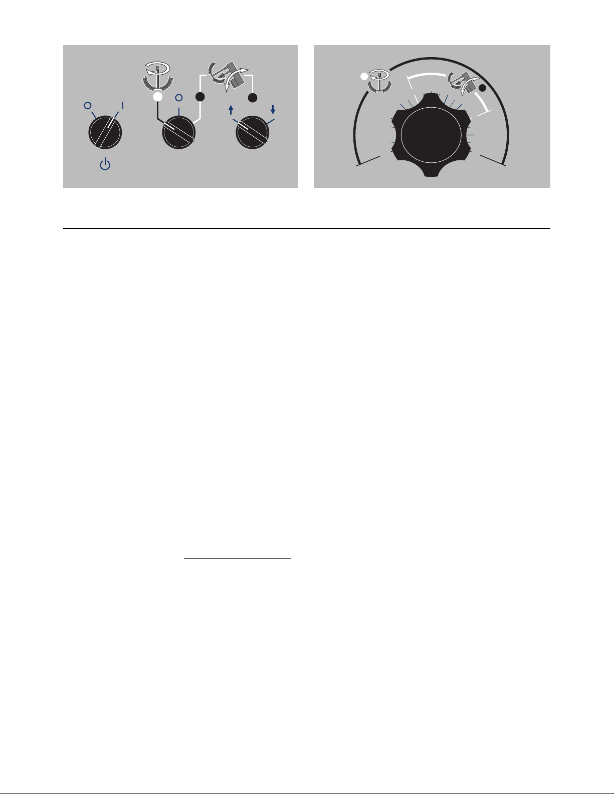
MAIN POWER
SWITCH
MIX/LIFT
SWITCH
UP/DOWN
SWITCH
MIXER SPEED CONTROL
SWITCH
Cleveland Range Mixer Kettles are simple and safe
to operate. The following tips will allow you to
maximize the use of your new mixer.
General Operation
1. Turn MAIN POWER SWITCH on.
2. Turn STEAM CONTROL VALVE to control heat
kettle.
1. To achieve optimum performance on tilting
kettles;
Before applying steam to a cold kettle, open the
DRAIN COCK to drain condensate from the
kettles jacket. Close drain cock when unit is fully
drained.
2. Allow unit to preheat before addition of product
to kettle. However when cooking egg and milk
products, the kettle should NOT be preheated,
as products of this nature adhere to hot cooking
surfaces. These types of foods should be
placed in the kettle before heating is begun.
3. An important part of kettle cleaning is to prevent
foods from drying on. For this reason, cleaning
should be completed immediately after cooked
foods are removed. Refer to the "Care and
Cleaning" instructions for detailed kettle washing
procedures.
4. If a mixer bridge is equipped with a temperature
probe for a controller or thermometer, the probe
must be submerged a minimum of three inches
in the product for accurate readings.
Safety
1. Close PRODUCT DISCHARGE VALVE before
filling the kettle.
2. When raising or lowering MIXER BRIDGE, insure
FAUCET SPOUT is not in the way of MAIN
AGITATOR ARM or damage to spout will result.
3. As a safety precaution the MIXER SPEED
CONTROL must first be turned to zero before
unit will start to mix.
4. Always remember, like a cooking pot the kettles
become very hot when cooking. Avoid contact
with bare skin.
Lifting & Lowering Bridge
WARNING: Insure FAUCET SPOUT is out of way
before raising or lowering bridge.
1. Turn MIX/LIFT SWITCH to lift icon "A".
2. Turn MIXER SPEED CONTROL to "0" and back
up to "5".
3. Turn and hold UP/DOWN SWITCH to up arrow to
raise or down arrow to lower.
Mixing
1. Turn MIX/LIFT SWITCH to mix icon "B".
2. Turn MIXER SPEED CONTROL SWITCH to "0"
and slowly adjust to desired speed.
3. Adjust SECONDARY SPEED CONTROL KNOB
to desired speed.
Tilting Kettle
1. Raise MIXER BRIDGE and swing to side.
2. For manual tilt: Turn HANDWHEEL.
3. For power tilt: Turn POWER TILT CONTROL
SWITCH.
WARNING: Do not tilt kettle when mixer agitators are
in kettle bowl.
Product Discharge Valve
1. For butterfly valve: Push handle in and pull
upwards to open.
2.. For air valve: Turn AIR REGULATOR SWITCH to
open or close.
Adding Water Manually
1. Locate FAUCET SPOUT over desired kettle.
2. Turn on HOT or COLD WATER VALVES.
Stagnant
Water
High Pressure
Spray Hose
Chloride Cleaners
Steel Pads
Wire Brush &
CLEANING INSTRUCTIONS
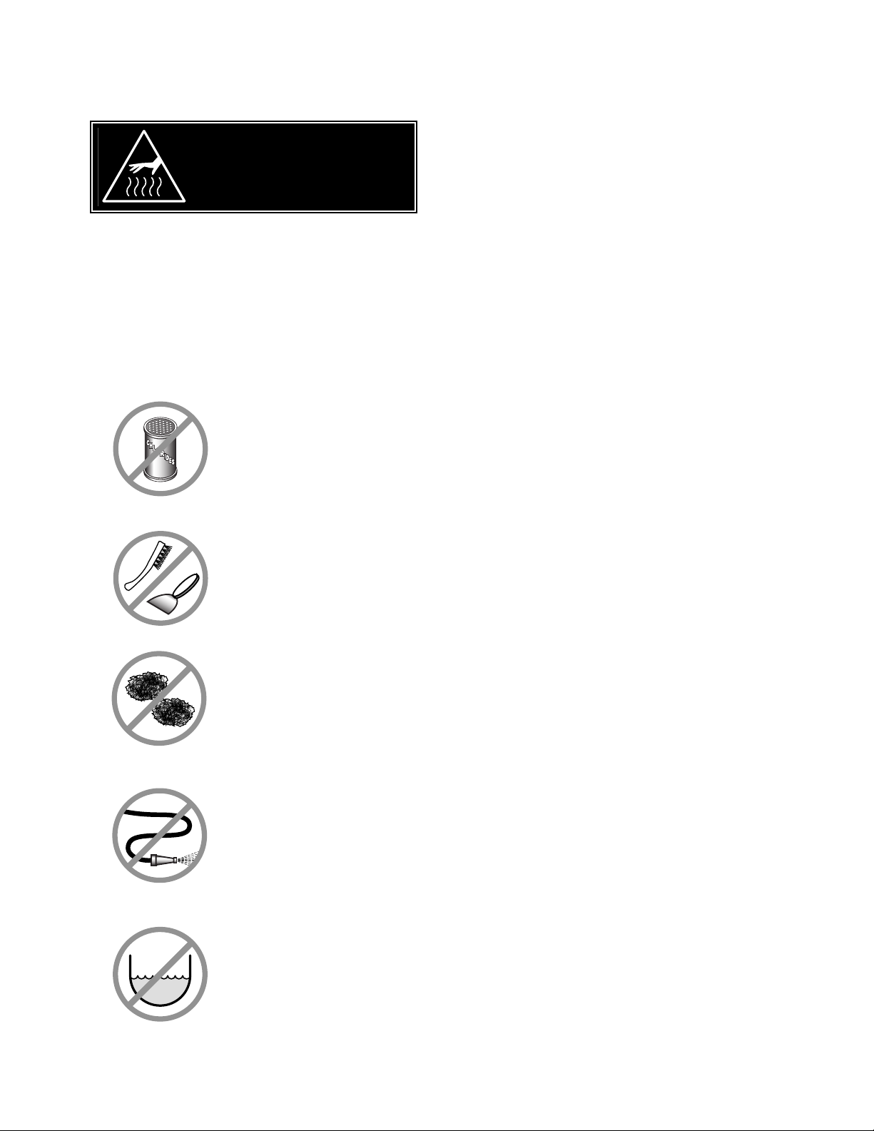
CAUTION
SURFACES MAY
BE EXTREMELY HOT!
CARE AND CLEANING
Cooking equipment must be cleaned regularly to
maintain its fast, efficient cooking performance and
to ensure its continued safe, reliable operation. The
best time to clean is shortly after each use (allow
unit to cool to a safe temperature).
WARNINGS
➩ Do not use detergents or
cleansers that are chloride
based or contain quaternary
salt.
➩ Do not use a metal bristle
brush or scraper.
CLEANING INSTRUCTIONS
1. Turn unit off.
2. Remove drain screen (if applicable). Thoroughly
wash and rinse the screen either in a sink or a
dishwasher.
3. Prepare a warm water and mild detergent solution in
the unit.
4. Remove food soil using a nylon brush.
5. Loosen food which is stuck by allowing it to soak at
a low temperature setting.
6. Drain unit.
7. Rinse interior thoroughly.
8. If the unit is equipped with a
VVaallvve
e
, clean as follows:
TTaannggeenntt DDrraaww--OOfff
a) Disassemble the draw-off valve first by turning
the valve knob counter-clockwise, then turning
the large hex nut counter-clockwise until the
valve stem is free of the valve body.
f
➩ Steel wool should never be
used for cleaning the stainless
steel.
➩ Unit should never be cleaned
with a high pressure spray
hose.
➩
Do not leave water sitting in unit
when not in use.
b) In a sink, wash and rinse the inside of the valve
body using a nylon brush.
c)
Use a nylon brush to clean tangent draw-off tube.
d) Rinse with fresh water.
e) Reassemble the draw-off valve by reversing the
procedure for disassembly. The valve's hex nut
should be hand tight only.
9. If the unit is equipped with a
BBuutttteerrffllyy VVaallvve
as follows:
a) Place valve in open position.
b) Wash using a warm water and mild detergent
solution.
c) Remove food deposits using a nylon brush.
d) Rinse with fresh water.
e) Leave valve open when unit is not in use.
e
, clean
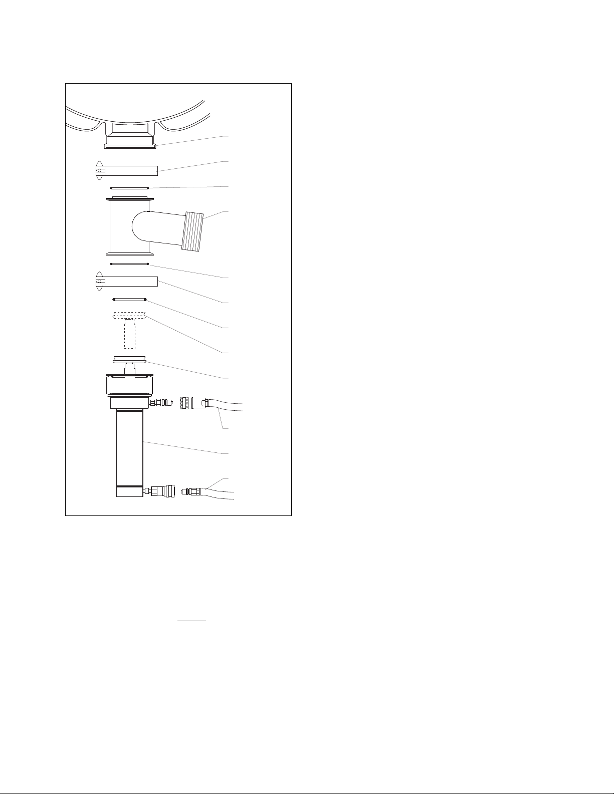
10. If the unit is equipped with a
AIR HOSE
AIR
CYLINDER
AIR HOSE
OPEN
POSITION
CLOSED
POSTITION
O-RING
CLAMP
O-RING
VALVE
TEE
O-RING
CLAMP
KETTLE
OUTLET
KETTLE
daily as follows:
AAiirr VVaallvve
e
, clean
11. Clean the scraper blades as follows:
a)
Remove retaining ring and slide scraper
blades off agitator arm.
b)
Place parts in a pan of warm water to soak.
c)
Clean in a sink, using a warm water and
mild detergent solution.
d)
Rinse with fresh water.
e)
Allow to dry thoroughly on a flat, clean
surface.
10. Using mild soapy water and a damp sponge,
wash the exterior, rinse, and dry.
NOTES
➩ For more difficult cleaning applications one of the
following can be used: alcohol, baking soda,
vinegar, or a solution of ammonia in water.
➩ Leave the cover off when the kettle is not in use.
Open product valve.
a)
b)
Disconnect air hoses.
c)
Remove air cylinder.
d)
Remove valve tee.
e)
Remove all O-rings.
f)
Clean air cylinder, do not
water. Wipe clean and sanitize.
g)
Clean and sanitize tee and O-rings.
h)
Grease and reinstall O-rings.
i)
Reinstall tee to kettle outlet.
j)
Reinstall air cylinder to bottom of tee.
k)
Reconnect air hoses.
l)
Close valve and check for alignment.
submerge in

STAINLESS STEEL EQUIPMENT CARE AND CLEANING
(Supplied courtesy of Nafem. For more information visit their web site at www.nafem.org)
Contrary to popular belief, stainless steels ARE susceptible to rusting.
Corrosion on metals is everywhere. It is recognized quickly on iron and
steel as unsightly yellow/orange rust. Such metals are called “active”
because they actively corrode in a natural environment when their atoms
combine with oxygen to form rust.
Stainless steels are passive metals because they contain other metals, like
chromium, nickel and manganese that stabilize the atoms. 400 series
stainless steels are called ferritic, contain chromium, and are magnetic;
300 series stainless steels are called austenitic, contain chromium and
nickel; and 200 series stainless, also austenitic, contains manganese,
nitrogen and carbon. Austenitic types of stainless are not magnetic, and
generally provide greater resistance to corrosion than ferritic types.
With 12-30 percent chromium, an invisible passive film covers the steel’s
surface acting as a shield against corrosion. As long as the film is intact
and not broken or contaminated, the metal is passive and stain-less. If the
passive film of stainless steel has been broken, equipment starts to
corrode. At its end, it rusts.
Enemies of Stainless Steel
There are three basic things which can break down stainless steel’s
passivity layer and allow corrosion to occur.
1. Mechanical abrasion
2. Deposits and water
3. Chlorides
Mechanical abrasion means those things that will scratch a steel surface.
Steel pads, wire brushes and scrapers are prime examples.
Water comes out of the faucet in varying degrees of hardness. Depending
on what part of the country you live in, you may have hard or soft water.
Hard water may leave spots, and when heated leave deposits behind that
if left to sit, will break down the passive layer and rust stainless steel. Other
deposits from food preparation and service must be properly removed.
Chlorides are found nearly everywhere. They are in water, food and table
salt. One of the worst chloride perpetrators can come from household and
industrial cleaners.
4. Treat your water.
Though this is not always practical, softening hard water can do much
to reduce deposits. There are certain filters that can be installed to
remove distasteful and corrosive elements. To insure proper water
treatment, call a treatment specialist.
5. Keep your food equipment clean.
Use alkaline, alkaline chlorinated or non-chloride cleaners at
recommended strength. Clean frequently to avoid build-up of hard,
stubborn stains. If you boil water in stainless steel equipment,
remember the single most likely cause of damage is chlorides in the
water. Heating cleaners that contain chlorides have a similar effect.
6. Rinse, rinse, rinse.
If chlorinated cleaners are used, rinse and wipe equipment and
supplies dry immediately. The sooner you wipe off standing water,
especially when it contains cleaning agents, the better. After wiping
equipment down, allow it to air dry; oxygen helps maintain the
stainless steel’s passivity film.
7. Never use hydrochloric acid (muriatic acid) on stainless steel.
8. Regularly restore/passivate stainless steel.
Recommended cleaners for specific situations
Job Cleaning Agent Comments
Routine cleaning Soap, ammonia, Apply with cloth or sponge
detergent, Medallion
Fingerprints & smears Arcal 20, Lac-O-Nu Provides barrier film
Ecoshine
Stubborn stains & Cameo, Talc, Zud, Rub in direction of polish lines
discoloration First Impression
Grease & fatty acids, Easy-off, De-Grease Excellent removal on all finishes
blood, burnt-on-foods It Oven Aid
Grease & oil Any good Apply with sponge or cloth
commercial detergent
Restoration/Passivation Benefit, Super Sheen
So what does all this mean? Don’t Despair!
Here are a few steps that can help prevent stainless steel rust.
1. Use the proper tools.
When cleaning stainless steel products, use non-abrasive tools. Soft
cloths and plastic scouring pads will not harm steel’s passive layer.
Stainless steel pads also can be used but the scrubbing motion must
be in the direction of the manufacturers’ polishing marks.
2. Clean with the polish lines.
Some stainless steel comes with visible polishing lines or “grain.”
When visible lines are present, always scrub in a motion parallel to the
lines. When the grain cannot be seen, play it safe and use a soft cloth
or plastic scouring pad.
3. Use alkaline, alkaline chlorinated or non-chloride containing cleaners.
While many traditional cleaners are loaded with chlorides, the industry
is providing an ever-increasing choice of non-chloride cleaners. If you
are not sure of chloride content in the cleaner used, contact your cleaner
supplier. If your present cleaner contains chlorides, ask your supplier if
they have an alternative. Avoid cleaners containing quaternary salts; it
also can attack stainless steel and cause pitting and rusting.
Review
1. Stainless steels rust when passivity (film-shield) breaks down as a
result of scrapes, scratches, deposits and chlorides.
2. Stainless steel rust starts with pits and cracks.
3. Use the proper tools. Do not use steel pads, wire brushes or scrapers
to clean stainless steel.
4. Use non-chlorinated cleaners at recommended concentrations. Use
only chloride- free cleaners.
5. Soften your water. Use filters and softeners whenever possible.
6. Wipe off cleaning agent(s) and standing water as soon as possible.
Prolonged contact causes eventual problems.
To learn more about chloride-stress corrosion and how to prevent it,
contact the equipment manufacturer or cleaning materials supplier.
Developed by Packer Engineering, Naperville, Ill., an independent testing
laboratory.
16
49
48
18
10
41
42
47
46
11
12
13A
13B
14
15
19
20
21
24
25
26
22 23
29
31
27
28
30
32
39
38
37
36
40
35
34
54
1
2
3
4
6
5
53
1
7
8
9
33
43
44
50
51
52
55
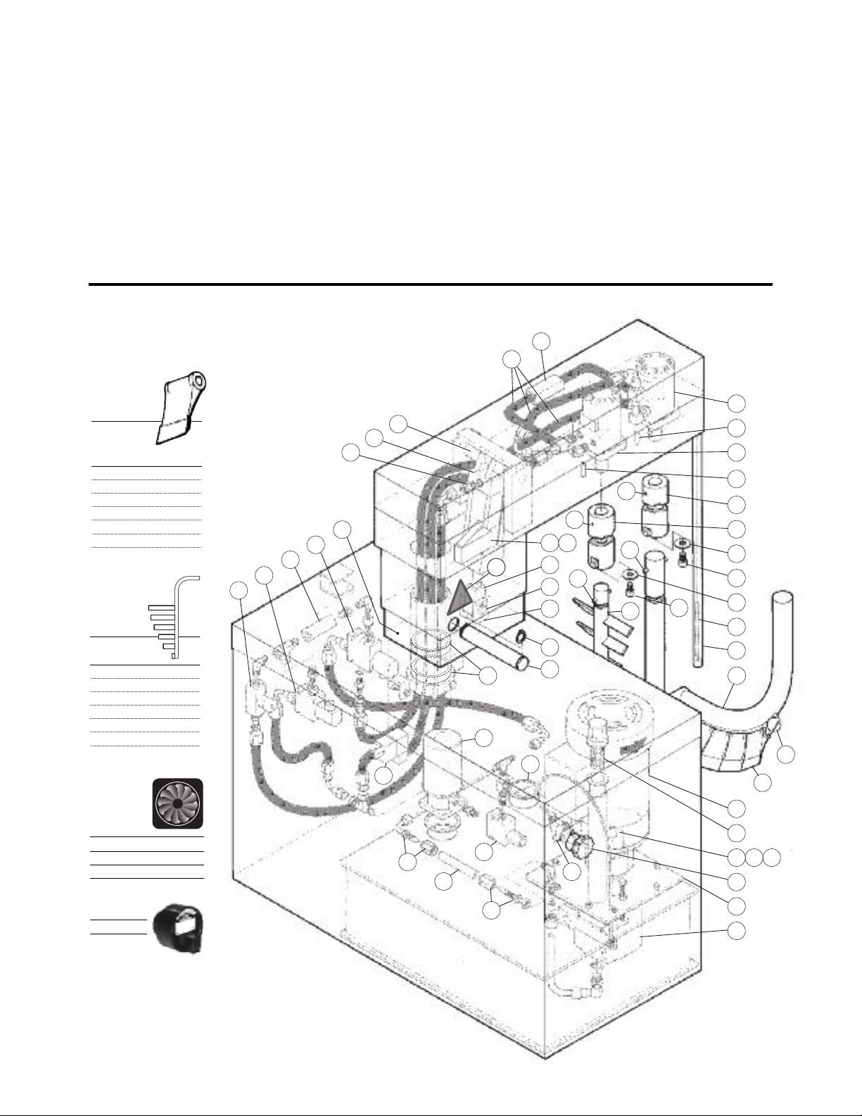
SERVICE PARTS
WARRANTY
Our Company supports a worldwide network of
Maintenance and Repair Centers. Contact your
nearest Maintenance and Repair Center for
replacement parts, service, or information
regarding the proper maintenance and repair of
your cooking equipment
HYDRAULIC COMPONENTS
(page 1 of 3)
In order to preserve the various agency safety
certification (UL, NSF, ASME/Ntl. Bd., etc.), only
factory-supplied replacement parts should be
used. The use of other than factory supplied
replacement parts will void warranty.
Scraper
Blades:
KETTLE
SIZE GAL. QUANTITY
40 22
60 26
80 30
100 34
125 38
150 38
Baffle
Arms:
KETTLE
SIZE - GAL.
40 KE01682-1
60 KE01682-2
80 KE01682-3
100 KE01682-4
125 KE01682-5
150 KE01682-6
Cooling
Fan:
Fan KE54860
Fan Cover KE601236
Fan Guard KE54861
Buzzer
KE603803
used after
April 2010
NNOOTTEE
Hoses order Part No.
RT00505 and specify
length required
:
: For Hydraulic
 Loading...