

Page 1
INSTALLATION, OPERATION AND SERVICE MANUAL
GAS TABLE TOP KETTLE -
MODEL: KGT-6-T
KGT-12-T
CLEVELAND RANGE INC.
1333 East 179th St.
Cleveland, Ohio
U.S.A. 44110
Toll Free 1-800-338-2204
SE95010 Rev.3
Page 2
FOR THE USER
IMPORTANT
POST IN A PROMINENT LOCATION, INSTRUCTIONS TO BE FOLLOWED IN THE EVENT
THE USER SMELLS GAS.THIS INFORMATION SHALL BE OBTAINED BY CONSULTING
YOUR LOCAL GAS SUPPLIER.
ALL SERVICE MUST BE PERFORMED BY A QUALIFIED CLEVELAND RANGE
TECHNICIAN.
RETAIN THIS MANUAL FOR YOUR REFERENCE.
WARNING: Improper installation,
adjustment, alteration, service or
maintenance can cause property
damage, injury or death. Read the
installation operating and
maintenance instructions
thoroughly before installing or
servicing this equipment.
FOR YOUR SAFETY
DO NOT STORE OR USE
GASOLINE OR ANY OTHER
FLAMMABLE LIQUIDS AND
VAPOURS IN THE VICINITY
OF THIS OR ANY OTHER
APPLIANCE.
Page 3

TABLE OF CONTENTS
Installation Inspection . . . . . . . . . . . . . . . . . . . . . . . . . . . . . . . . . . . . . . . . . . 1
Shipping Damage Instructions . . . . . . . . . . . . . . . . . . . . . . . . . . . 1
General . . . . . . . . . . . . . . . . . . . . . . . . . . . . . . . . . . . . . . . . . . . . 1
Clearance Requirements. . . . . . . . . . . . . . . . . . . . . . . . . . . . . . . . 1
Assembly . . . . . . . . . . . . . . . . . . . . . . . . . . . . . . . . . . . . . . . . . . . 1
Gas . . . . . . . . . . . . . . . . . . . . . . . . . . . . . . . . . . . . . . . . . . . . . . 1-2
Electrical . . . . . . . . . . . . . . . . . . . . . . . . . . . . . . . . . . . . . . . . . . . 2
Ventilation . . . . . . . . . . . . . . . . . . . . . . . . . . . . . . . . . . . . . . . . . . 2
Water . . . . . . . . . . . . . . . . . . . . . . . . . . . . . . . . . . . . . . . . . . . . . . 2
Installation Checks. . . . . . . . . . . . . . . . . . . . . . . . . . . . . . . . . . . . 2
Cleaning . . . . . . . . . . . . . . . . . . . . . . . . . . . . . . . . . . . . . . . . . . . . 2
Operating Instructions General Parts Drawing . . . . . . . . . . . . . . . . . . . . . . . . . . . . . . . . 3
Operating the Kettle . . . . . . . . . . . . . . . . . . . . . . . . . . . . . . . . . . . 4
Marine Lock. . . . . . . . . . . . . . . . . . . . . . . . . . . . . . . . . . . . . . . . . 4
Cleaning Instructions Care & Cleaning . . . . . . . . . . . . . . . . . . . . . . . . . . . . . . . . . . . . . 5
Marine Lock. . . . . . . . . . . . . . . . . . . . . . . . . . . . . . . . . . . . . . . . . 5
Service Parts Warranty. . . . . . . . . . . . . . . . . . . . . . . . . . . . . . . . . . . . . . . . . . . . 6
Faucet Assembly . . . . . . . . . . . . . . . . . . . . . . . . . . . . . . . . . . . . . 6
Main Components. . . . . . . . . . . . . . . . . . . . . . . . . . . . . . . . . . . . . 7
Console . . . . . . . . . . . . . . . . . . . . . . . . . . . . . . . . . . . . . . . . . . . . 8
Component Mounting Bracket Assembly. . . . . . . . . . . . . . . . . . . . 9
Piping Assembly . . . . . . . . . . . . . . . . . . . . . . . . . . . . . . . . . . . . . 10
Maintenance Inspection & Maintenance Check List . . . . . . . . . . . . . . . . . . . . 11
Calibrating Procedure . . . . . . . . . . . . . . . . . . . . . . . . . . . . . . . . 12
Vacuum Leak Test. . . . . . . . . . . . . . . . . . . . . . . . . . . . . . . . . . . . 12
Pressure Relief Valve Periodic Testing Procedure . . . . . . . . . . . . 12
Reservoir Fill Procedures. . . . . . . . . . . . . . . . . . . . . . . . . . . . . . 13
Kettle Venting Instructions . . . . . . . . . . . . . . . . . . . . . . . . . . . . . 14
Repairing Leaks in Steam Jacketed Kettle Fittings . . . . . . . . . . . 14
Kettle Jacket Filling & Draining Procedures . . . . . . . . . . . . . . . 15
Operating Sequences . . . . . . . . . . . . . . . . . . . . . . . . . . . . . . . . . 16
Field Conversion Instructions -
Natural Gas to Propane Gas . . . . . . . . . . . . . . . . . . . . . . . . . 17
Wiring Diagram . . . . . . . . . . . . . . . . . . . . . . . . . . . . . . . . . . . . . 18
Page 4
1
INSPECTION
Before unpacking visually inspect the unit for evidence
of damage during shipping.
If damage is noticed, do not unpack the unit, follow
shipping damage instructions.
SHIPPING DAMAGE
INSTRUCTIONS
If shipping damage to the unit is discovered or
suspected, observe the following guidelines in
preparing a shipping damage claim.
1. Write down a description of the damage or the
reason for suspecting damage as soon as it is
discovered. This will help in filling out the claim
forms later.
2. As soon as damage is discovered or suspected,
notify the carrier that delivered the shipment.
3. Arrange for the carrier's representative to examine
the damage.
4. Fill out all carrier claims forms and have the
examining carrier sign and date each form.
GENERAL
Installation of the kettle must be accomplished by
qualified installation personnel working to all applicable
local and national codes. Improper installation of
product could cause injury or damage.
This equipment is built to comply with applicable
standards for manufacturers. Included among those
approval agencies are: UL, A.G.A., NSF, ASME/N.Bd.,
CSA, CGA, ETL, and others. Many local codes exist,
and it is the responsibility of the owner/installer to
comply with these codes.
Observe all clearance requirements to provide proper
make-up air flow. Do not obstruct the flow of combustion
and ventilation air. Check rating plate to ensure that
kettle has been equipped to operate with the type of
gas available at the installation.
Dimensions and clearance specifications are shown on
the specification sheet and in the Clearance
Requirements section.
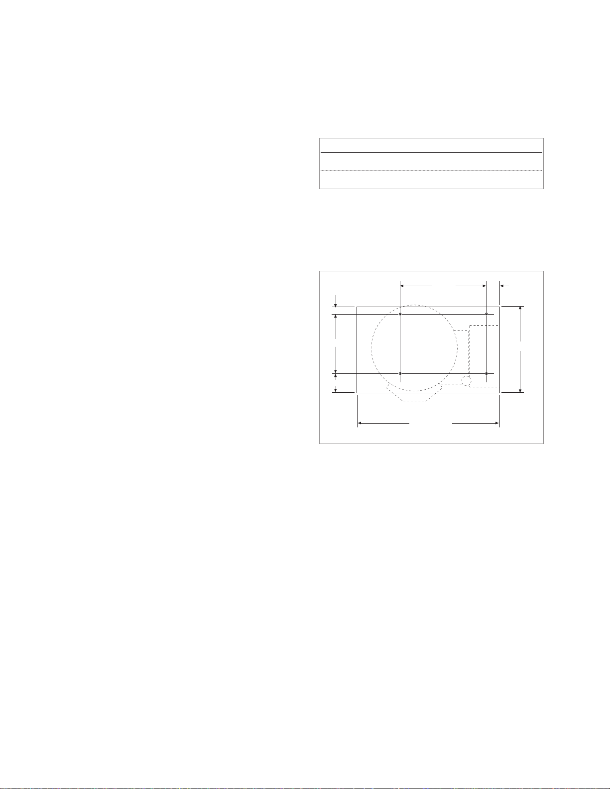
CLEARANCE REQUIREMENTS
CLEARANCE REQUIREMENTS TO COMBUSTIBLE
AND NONCOMBUSTIBLE SURFACES.
NOTE: To prevent removal of unit for servicing, allow
sufficient room on right hand side for servicing.
ASSEMBLY
Base Mounting Diagram
Table-top models must be positioned on a firm, level
stand, or existing counter top, and bolted in place. These
models are supplied with four threaded mounting
bushings welded to the underside of the base. An
optional support stand with level adjustable legs is
available. Once the kettle is secure, screw tilt handle into
the threaded hole provided at the right side of kettle.
GAS
ENSURE THE GAS SUPPLY MATCHES THE
KETTLE'S REQUIREMENTS AS STATED ON THE
RATING PLATE.
It is recommended that a sediment trap (drip leg) be
installed in the gas supply line. If the gas pressure
exceeds 14” water column, a pressure regulator must
be installed, to provide a maximum of 14” water column
gas pressure to the gas control valve.
Connect the gas line to the manual valve located at the
rear of the control box.
Model # Back Left Side Right Side
KGT-16-T 4” 0 0
KGT-12-T 4” 0 0
INSTALLATION
1 1/4"
10"
3 1/4"
14 1/2" 2 1/4"
14 1/2"
24" (6 gallon)
27" (12 gallon)
Page 5

2
Installation must be in accordance with local codes
and/or the National Fuel Gas Code ANSI Z223.1 Latest
Edition (USA) or the latest Installation Codes for Gas
Burning Appliances and Equipment CAN/ CGA B149.1
and CAN/ CGA B149.2 (Canada). Use a gas pipe joint
compound which is resistant to L.P. gas. Test all pipe
joints for leaks with soap and water solution. Ensure that
the gas pressure regulator is set for the manifold
pressure indicated on the gas rating plate.
The appliance and its individual shut-off valve must be
disconnected from the gas supply piping system during
any pressure testing of that system at test pressures in
excess of 1/2 psi (3.45 kPa). The appliance must be
isolated from the gas supply piping system by closing
its individual manual shut-off valve during any pressure
testing of the gas supply piping system at test
pressures equal to or less than 1/2 psi (3.45 kPa).
ELECTRICAL
ENSURE THE ELECTRICAL SUPPLY MATCHES THE
KETTLE'S REQUIREMENTS AS STATED ON THE
RATING LABEL.
A cord and plug are supplied with the unit. Simply plug
the unit into any grounded outlet rated for a minimum of
10 amps. The wiring diagram is located on the back of
the console access panel.
WARNING: Electrical Grounding Instructions.
This unit is equipped with a three-prong (grounding) plug
for your protection against shock hazard and should be
plugged directly into a properly grounded three-prong
receptacle. Do not cut or remove the grounding prong
from this plug. Standard supply voltage is 115 volts A.C.,
however, optional A.C. voltages can be supplied on
special order. A separate fused disconnect switch must
be supplied and installed in the high voltage electrical
supply line. The kettle when installed, must be electrically
installed and grounded in accordance with local codes,
or in the absence of local codes, with National Electrical
Code, ANSI/NFPA 7-1990 (USA) or the Canadian
Electrical Code, CSA C22.1, Part 1 (Canada).
VENTILATION
Gas fired kettles are only to be installed under a
ventilation hood in a room which has provisions for
adequate make up air. Further information can be
obtained by referring to the U.S.A. National Fire
Protection Associations NFPA96 regulations. These
standards have also been adopted by the National
Building Code in Canada.
WATER
The sealed jacket of the gas-fired kettle is precharged
with the correct amount of a water-based formula, and
therefore, no water connection is required to the kettle
jacket. The kettle can be equipped with optional hot and
cold water taps, the taps require 1/2" copper tubing as
supply lines.
INSTALLATION CHECKS
Although the kettle has been thoroughly tested before
leaving the factory, the installer is responsible for
ensuring the proper operation of kettle once installed.
DO NOT ATTEMPT TO OPERATE THIS APPLIANCE
DURING A POWER FAILURE.
KEEP APPLIANCE AND AREA FREE AND CLEAR OF
COMBUSTIBLES.
1. Supply power to the kettle by placing the fused
disconnect switch to the "ON" position.
2. Before turning the kettle on, read the
vacuum/pressure gauge. The gauge's needle
should be in the green zone. If the needle is in the
"VENT AIR" zone, follow air venting procedure.
3. Place the kettle's power on/off switch to the "ON"
position.
4. Turn the temperature control knob to "MIN .". The green
LED light should remain lit, indicating the burner is lit,
until the set temperature is reached. Then the green
light will cycle on and off, indicating the burner is
cycling on and off to maintain temperature.
5. Tilt the kettle forward. The red "LOW WATER" light
should be lit when the kettle is in a tilted position.
This light indicates that the burner has automatically
been shut off by the kettle's safety circuit. This is a
normal condition when the kettle is in a tilted
position.
6. Raise the kettle to the upright position. The red "low
water" light should go out when the kettle is upright.
If the red light remains lit in the upright position, it
indicates a low water condition, and water must be
added to the reservoir before the kettle can be
operated. Refer to the "Reservoir Fill Procedures", on
the kettle's label, for details.
7. Turn the temperature control knob to "MAX." and
allow the kettle to preheat. The green light should
remain on until the set temperature is reached. Then
the green light will cycle ON and OFF, indicating the
burner is cycling ON and OFF to maintain
temperature.
CLEANING
After installation the kettle must be thoroughly cleaned
and sanitized prior to cooking. See complete cleaning
instructions in this manual (page 5).
Page 6
3
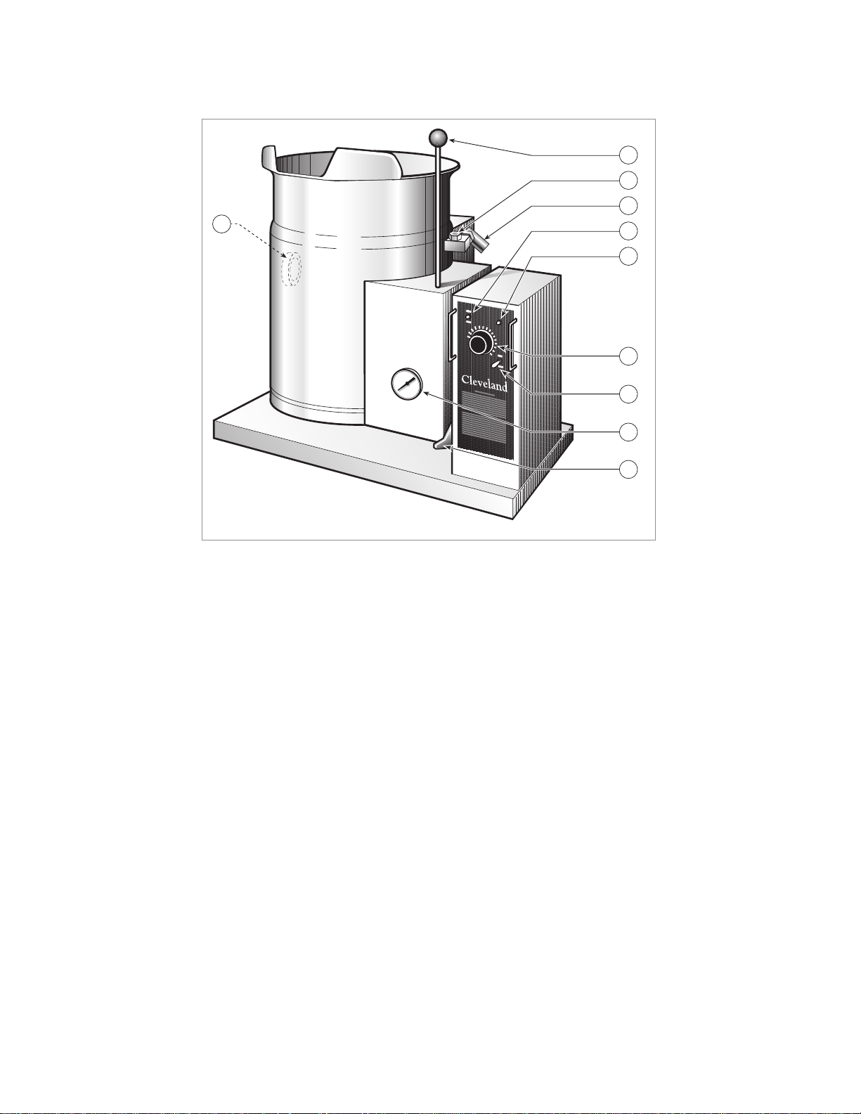
OPERATING INSTRUCTIONS
General Parts Drawing
ITEM # DESCRIPTION FUNCTION
1. On-Off Toggle Switch Controls electrical power to kettle.
2. Solid State Temperature This control allows the operator to adjust the kettle temperature in
Control Knob increments from MIN. to MAX. (see Temperature Range Chart on
page 4 of this manual.
3. Heat Indicator Light (Green) When lit, indicates that the kettle burner is on.
Cycles ON-OFF with burner.
4. Low Water Indicator Light (Red) When lit, indicates that the kettle is low on water and will not operate
in this condition (see Reservoir Fill Procedures on page 13 of this
manual).
5. Vacuum/Pressure Gauge Indicate steam pressure in PSI inside steam jacket as well as
vacuum in inches of mercury.
6. Pressure Relief Valve This valve is used to vent the kettle and in the unlikely event there is
an excess steam build-up in the jacket, this valve opens
automatically to relieve this pressure.
7. Plug Nut Plug nut is used for refilling the kettle with water (see "Kettle Venting
Instructions" and "Reservoir Fill Procedures" on pages 13 and 14 of
this manual).
8. Tilting Handle Used for tilting the kettle.
9. Marine Lock Prevents unit from accidental tilting.
10. Water Level Sight Glass Displays water level in steam jacket.
8
7
6
10
4
3
2
1
5
9
Page 7
4
OPERATING THE KETTLE
DO NOT ATTEMPT TO OPERATE THIS APPLIANCE
DURING A POWER FAILURE.
KEEP APPLIANCE AND AREA FREE AND CLEAR OF
COMBUSTIBLES.
DO NOT LEAN ON OR PLACE OBJECTS ON KETTLE
LIP. SERIOUS INJURY COULD RESULT IF KETTLE
TIPPED OVER, SPILLING HOT CONTENTS.
1. Before turning kettle on, read the
Vacuum/Pressure Gauge (5). The gauges
needle should be in the green zone. If the
needle is in the "VENT AIR" zone, refer to the
"Kettle Venting Instructions". Any air that may
be present will increase cooking times. Once
heated, the kettle's normal maximum
operating pressure is approximately 10-12
psi, while cooking a water base product.
2. Place the kettle's On-Off Toggle Switch (1) to
the "ON" position.
Temperature Range Chart
3. Preheat the kettle by turning the Solid State
Temperature Control Knob (2) to the desired
temperature setting (see Temperature Range
Chart on page 4). The Heat Indicator Light
(Green) (3) will remain lit, indicating the
burner is lit, until the temperature setting is
reached. When the green light goes off, the
heaters are off, and preheating is complete.
4. Place food product into the kettle. The green
light will cycle on and off indicating the burner
is cycling on and off to maintain the set
temperature.
NOTE: When cooking egg and milk products, the kettle
should not be preheated, as products of this nature
adhere to hot cooking surfaces. These types of food
should be placed in the kettle before heating is begun.
NOTE: The Low Water Indicator Light (Red) (4) should
not be lit during kettle operation. This light indicates that
the burner has been automatically shut off by the
kettle's safety circuit. It is normal for the red light to
come on when the kettle is in a tilted position. However,
the kettle cannot be operated when the red light
remains lit while the kettle is in the upright position. This
indicates a low water condition, and water must be
added to the reservoir. Refer to "Reservoir Fill
Procedures" in this manual for details.
5. When cooking is completed place On-Off
Toggle Switch (1) to the "OFF' position.
NOTE: A five minute complete shut-of period is
required before relighting.
6. Pour the contents of the kettle into an
appropriate container by tilting the kettle
forward. Care should be taken to pour slowly
enough to avoid splashing off the product.
NOTE: As with cleaning food soil from any cookware,
an important part of kettle cleaning is to prevent food
from drying on. For this reason, cleaning should be
completed immediately after cooked foods are
removed. Refer to the "Care and Cleaning Instructions"
for detailed kettle washing procedures.
MARINE LOCK
If your unit is equipped with a
marine lock to prevent
accidental tilting, the following
procedure should be used to tilt
the kettle.
1. Grasp the tilt handle with your right hand.
2. Push the marine lock button down with your
left hand to unlock tilting mechanism.
3. Pull the handle to tilt kettle.
4. When you return the kettle to its upright
position the marine lock will latch
automatically.
Temperature Approximate
Control Product Temperature
Setting °F °C
MIN. 120 49
1. 130 54
2. 145 63
3. 160 71
4. 170 77
5. 185 85
6. 195 91
7. 210 99
8. 230 110
9. 245 118
MAX.
265 130
NOTE: Certain combinations of ingredients will
result in temperature variations
Page 8

5
CARE AND CLEANING
Your kettle must be cleaned regularly to maintain its
fast, efficient cooking performance, and to ensure its
continued safe, reliable operation.
WARNING: Do not use chloride base detergents.
1. Place the kettle's On-Off Toggle Switch (1) to
the "OFF" position.
2. Prepare a warm water and mild detergent
solution in the kettle.
3. Remove food soil inside the kettle using a
nylon brush. Do not use a metal bristle brush,
as this may permanently damage the kettle's
stainless steel surface.
4. Loosen food which is stuck to the kettle by
allowing it to soak at a low temperature
setting.
5. Tilt kettle forward to drain wash water.
6. Rinse kettle interior thoroughly, then drain the
rinse water.
7. Using mild soapy water and a damp sponge,
wash the exterior of the kettle, rinse, and dry.
8. Leave the cover off when the kettle is not in
use.
NOTE: For more difficult cleaning applications one of
the following can be used: alcohol, baking soda,
vinegar, or a solution of ammonia in water. Avoid the use
of chloride cleansers, which may damage the kettle's
stainless steel surface.
WARNING: Steel wool should never be used for
cleaning the cooking chamber of the kettle. Particles of
steel wool become embedded in the cooking surface
and rust, which may corrode the stainless steel.
MARINE LOCK
Use a small nylon bristle brush to remove food and
debris from pivot point. If lock is sticking have
maintenance disassemble and clean pieces individually
and reassemble.
CLEANING INSTRUCTIONS
Page 9

6
SERVICE PARTS
WARRANTY
Our Company supports a worldwide network of Maintenance and Repair Centers. Contact your nearest Maintenance and
Repair Centre for replacement parts, service, or information regarding the proper maintenance and repair of your cooking
equipment
In order to preserve the various agency safety certification (UL, NSF, ASME/Ntl. Bd., etc.), only factory-supplied
replacement parts should be used. The use of other than factory supplied replacement parts will void warranty.
FAUCET ASSEMBLY
ITEM PART DESCRIPTION QTY.
NO. NO.
1. KE50825-2 3/4" Spout . . . . . . . . . . . . . . . . . . . . .1
2. FA95022 Retaining Ring . . . . . . . . . . . . . . . . . .1
3. FA05002-19 "O" Ring . . . . . . . . . . . . . . . . . . . . . . .1
4. KE51736 Long Faucet Nut . . . . . . . . . . . . . . . .1
5. SE50020 Hot Water Stem Assembly . . . . . . . . .1
(Double Pantry only)
6. SE50021 Cold Water Stem Assembly . . . . . . . .1
7. KE51401 Single Pantry Body . . . . . . . . . . . . . .1
(c/w Item No. 6)
8. KE50335 Adapter Washer . . . . . . . . . . . . . . . .1
(Single Pantry only)
9. KE51403 Double Pantry Body . . . . . . . . . . . . .1
(c/w Item No. 5&6)
10. KE54159 Faucet Mounting Bracket . . . . . . . . . .1
11. FA11258 Hex Cap Screw . . . . . . . . . . . . . . . . .2
12. FA30505 Washer . . . . . . . . . . . . . . . . . . . . . . .2
13. FA21008 Hex Nut . . . . . . . . . . . . . . . . . . . . . . .2
14. SE50447 Washer Horseshoe . . . . . . . . . . . . . .1
1
1
2
2
3
3
4
4
5
9
10
10
13
8
12
11
13
14
12
11
7
6
6
Page 10

7
MAIN COMPONENTS
ITEM NO. PART NO. DESCRIPTION QTY.
1. SK50403 Bronze Bearing . . . . . . . . . . . . . . . . . . . . . . . . . . . . . . . . . . . . . . . . . . . . . . . .1
2. SK50434 Washer . . . . . . . . . . . . . . . . . . . . . . . . . . . . . . . . . . . . . . . . . . . . . . . . . . . . . .1
3. KE00349 Bolt, Modified . . . . . . . . . . . . . . . . . . . . . . . . . . . . . . . . . . . . . . . . . . . . . . . . .1
4. KE54247 Hex Bolt, 14-20x3/4" lg. . . . . . . . . . . . . . . . . . . . . . . . . . . . . . . . . . . . . . . . . .2
5. KE02004-1 Trunnion Support Bar and Brace Assembly (6 gallon) . . . . . . . . . . . . . . . . . . .1
5. KE02004-2 Trunnion Support Bar and Brace Assembly (12 gallon) . . . . . . . . . . . . . . . . . .1
6. KE50474 Foot . . . . . . . . . . . . . . . . . . . . . . . . . . . . . . . . . . . . . . . . . . . . . . . . . . . . . . . .1
7. KE50429-2 Pressure Gauge . . . . . . . . . . . . . . . . . . . . . . . . . . . . . . . . . . . . . . . . . . . . . . .1
8. FA05002-21 "O" Ring. . . . . . . . . . . . . . . . . . . . . . . . . . . . . . . . . . . . . . . . . . . . . . . . . . . . . .1
9. FI05022 Compression Fitting, Brass . . . . . . . . . . . . . . . . . . . . . . . . . . . . . . . . . . . . . . .1
10. KE50151-E Knob . . . . . . . . . . . . . . . . . . . . . . . . . . . . . . . . . . . . . . . . . . . . . . . . . . . . . . .1
11. KE54670-2 Handle, 6 gallon . . . . . . . . . . . . . . . . . . . . . . . . . . . . . . . . . . . . . . . . . . . . . . .1
KE54670-3 Handle, 12 gallon . . . . . . . . . . . . . . . . . . . . . . . . . . . . . . . . . . . . . . . . . . . . . .1
12. FA05002-29 "O" Ring for Handle . . . . . . . . . . . . . . . . . . . . . . . . . . . . . . . . . . . . . . . . . . . . .1
13. KE95457 Label . . . . . . . . . . . . . . . . . . . . . . . . . . . . . . . . . . . . . . . . . . . . . . . . . . . . . . .1
14. FA11258 Hex Capa Screw, 14-20x3/4" lg. . . . . . . . . . . . . . . . . . . . . . . . . . . . . . . . . . . .4
15. SA95116 Marine Lock Replacement Kit . . . . . . . . . . . . . . . . . . . . . . . . . . . . . . . . . . . . .1
16. KE50997 Blow Down Tube . . . . . . . . . . . . . . . . . . . . . . . . . . . . . . . . . . . . . . . . . . . . . . .1
17. KE51723-1 Safety Valve . . . . . . . . . . . . . . . . . . . . . . . . . . . . . . . . . . . . . . . . . . . . . . . . . .1
18. KE54676 Bolt c/w "O" Ring Seal . . . . . . . . . . . . . . . . . . . . . . . . . . . . . . . . . . . . . . . . . . .1
20. SK50562 Cord Plug . . . . . . . . . . . . . . . . . . . . . . . . . . . . . . . . . . . . . . . . . . . . . . . . . . . .1
21. KE54721-2 Water Tight Fitting . . . . . . . . . . . . . . . . . . . . . . . . . . . . . . . . . . . . . . . . . . . . . .1
22. KE54468 Water Level Sight Glass . . . . . . . . . . . . . . . . . . . . . . . . . . . . . . . . . . . . . . . . .1
23. KE52196-1 Plug Button . . . . . . . . . . . . . . . . . . . . . . . . . . . . . . . . . . . . . . . . . . . . . . . . . . .1
24. KE53316 Safety Thermostat . . . . . . . . . . . . . . . . . . . . . . . . . . . . . . . . . . . . . . . . . . . . . .1
25. KE50294-1 Mercury Switch . . . . . . . . . . . . . . . . . . . . . . . . . . . . . . . . . . . . . . . . . . . . . . . .1
26. KE00515 Thermistor Assembly . . . . . . . . . . . . . . . . . . . . . . . . . . . . . . . . . . . . . . . . . . .1
27. KE50556-1 Water Level Probe . . . . . . . . . . . . . . . . . . . . . . . . . . . . . . . . . . . . . . . . . . . . .1
11
22
33
4
5
6
7 8 9
10
11
12
SEE
FAUCET
DRAWING
14
15
16
17
18
20
21
22
23
24
25
26
27
13
Page 11

8
CONSOLE
ITEM NO. PART NO. DESCRIPTION QTY.
1. KE50504 Switch, Toggle . . . . . . . . . . . . . . . . . . . . . . . . . . . . . . . . . . . . . . . . . .1
2. SK50062 Rubber Boot . . . . . . . . . . . . . . . . . . . . . . . . . . . . . . . . . . . . . . . . . . . .1
3. KE50988-2 Potentiometer . . . . . . . . . . . . . . . . . . . . . . . . . . . . . . . . . . . . . . . . . . .1
4. KE51005 Rubber Boot . . . . . . . . . . . . . . . . . . . . . . . . . . . . . . . . . . . . . . . . . . . .1
5. KE50569-1 Knob, Potentiometer . . . . . . . . . . . . . . . . . . . . . . . . . . . . . . . . . . . . . .1
6. KE50567-1 L.E.D., Red . . . . . . . . . . . . . . . . . . . . . . . . . . . . . . . . . . . . . . . . . . . . .1
7. FA05002-18 "O" Ring . . . . . . . . . . . . . . . . . . . . . . . . . . . . . . . . . . . . . . . . . . . . . . .2
8. KE50568-1 L.E.D., Green . . . . . . . . . . . . . . . . . . . . . . . . . . . . . . . . . . . . . . . . . . .1
9. KE53469-2 Ignition Control Box . . . . . . . . . . . . . . . . . . . . . . . . . . . . . . . . . . . . . .1
10. KE54308 High Voltage Lead Assembly . . . . . . . . . . . . . . . . . . . . . . . . . . . . . . .1
11. KE54309 Low Voltage Lead Assembly . . . . . . . . . . . . . . . . . . . . . . . . . . . . . . . .1
12. WH KGT Wiring Harness . . . . . . . . . . . . . . . . . . . . . . . . . . . . . . . . . . . . . . . . . .1
13. F01518-1 Gas Shut-Off Valve . . . . . . . . . . . . . . . . . . . . . . . . . . . . . . . . . . . . . . .1
14. FA05002-25 "O" Ring . . . . . . . . . . . . . . . . . . . . . . . . . . . . . . . . . . . . . . . . . . . . . . .1
15. KE54434 Trunnion Washer . . . . . . . . . . . . . . . . . . . . . . . . . . . . . . . . . . . . . . . . .1
16. FA95050 Retaining Ring . . . . . . . . . . . . . . . . . . . . . . . . . . . . . . . . . . . . . . . . . .1
TO MAIN GAS
SUPPLY
SEE COMPONENT MOUNTING
BRACKET ASSEMBLY DRAWING
SEE PIPING
ASSEMBLY
DRAWING
12
11
10
9
6
7
8
7
4
5
2
3
1
13
16
14
15
Page 12

9
COMPONENT MOUNTING BRACKET ASSEMBLY
ITEM NO. PART NO. DESCRIPTION QTY.
1-9 KE01928 Component Plate Assembly . . . . . . . . . . . . . . . . . . . . . . . . . . . . . . . .1
1. KE01927 Component Plate Weldment . . . . . . . . . . . . . . . . . . . . . . . . . . . . . . . .1
2. KE50753-7 Relay . . . . . . . . . . . . . . . . . . . . . . . . . . . . . . . . . . . . . . . . . . . . . . . . .1
4. KE53838-20 Transformer, 120/24 . . . . . . . . . . . . . . . . . . . . . . . . . . . . . . . . . . . . . .1
KE53838-18 Transformer, 220/24 . . . . . . . . . . . . . . . . . . . . . . . . . . . . . . . . . . . . . .1
5. KE53838-19 Transformer, 120/16 . . . . . . . . . . . . . . . . . . . . . . . . . . . . . . . . . . . . . .1
KE53838-21 Transformer, 220/16 . . . . . . . . . . . . . . . . . . . . . . . . . . . . . . . . . . . . . .1
6. KE00458 Solid State Control Box . . . . . . . . . . . . . . . . . . . . . . . . . . . . . . . . . . . .1
7. KE50303 Box Holder . . . . . . . . . . . . . . . . . . . . . . . . . . . . . . . . . . . . . . . . . . . . .1
8. FA11089 Screw, #8-32x1/4 lg. . . . . . . . . . . . . . . . . . . . . . . . . . . . . . . . . . . . . . .2
9. FA11056 Screw, #6-32x1/2 lg. . . . . . . . . . . . . . . . . . . . . . . . . . . . . . . . . . . . . . .2
2
1
6
8
5
4
7
Page 13

10
PIPING ASSEMBLY
ITEM NO. PART NO. DESCRIPTION QTY.
1. KE54667 Gas Burner Tube, 12 gallon kettle . . . . . . . . . . . . . . . . . . . . . . . . . . . .1
KE54667-1 Gas Burner Tube, 6 gallon kettle . . . . . . . . . . . . . . . . . . . . . . . . . . . . .1
2. KE02012 Compression Fitting and Nipple Assembly . . . . . . . . . . . . . . . . . . . . .1
3. KE01921 Reducing Elbow Assembly . . . . . . . . . . . . . . . . . . . . . . . . . . . . . . . . .1
4. FI05222-1 Swivel Elbow, Modified . . . . . . . . . . . . . . . . . . . . . . . . . . . . . . . . . . . .1
5. FI05163-1 Adapter, 1/2 NPT . . . . . . . . . . . . . . . . . . . . . . . . . . . . . . . . . . . . . . . .1
6. KE53515-1 Gas Valve, Modified . . . . . . . . . . . . . . . . . . . . . . . . . . . . . . . . . . . . . .1
7. FI00134 Street Elbow, 3/4" NPT . . . . . . . . . . . . . . . . . . . . . . . . . . . . . . . . . . . .1
8. KE01929 Feed Pipe Assembly . . . . . . . . . . . . . . . . . . . . . . . . . . . . . . . . . . . . . .1
9. KE01500-2 Gas Burner Assembly, 12 gallon kettle . . . . . . . . . . . . . . . . . . . . . . . .1
KE01500-3 Gas Burner Assembly, 6 gallon kettle . . . . . . . . . . . . . . . . . . . . . . . . .1
10. KE53406-11 Gas Orifice, Natural Gas, 12 gallon kettle . . . . . . . . . . . . . . . . . . . . . .1
KE53406-1 Gas Orifice, Natural Gas, 6 gallon kettle . . . . . . . . . . . . . . . . . . . . . . .1
KE53406-12 Gas Orifice, Propane Gas, 12 gallon kettle . . . . . . . . . . . . . . . . . . . . .1
KE53406-2 Gas Orifice, Propane Gas, 6 gallon kettle . . . . . . . . . . . . . . . . . . . . . .1
11. KE54666 Orifice Support Block . . . . . . . . . . . . . . . . . . . . . . . . . . . . . . . . . . . . .1
12. KE54700 Orifice Support Block, 6 gallon kettle only . . . . . . . . . . . . . . . . . . . . .1
13. FI05198-5 Compression Elbow . . . . . . . . . . . . . . . . . . . . . . . . . . . . . . . . . . . . . .1
14. KE53437-1 Ignitor . . . . . . . . . . . . . . . . . . . . . . . . . . . . . . . . . . . . . . . . . . . . . . . . .1
3
1
2
4
5
6
7
8
9
10
11
12
13
14
Page 14

11
Cleveland Range equipment requires little preventative maintenance. We do however provide the following
chart as a guideline for inspection and maintenance to keep your unit functioning at 100%.
INSPECTION AND MAINTENANCE CHECK LIST
The following check should be completed every six months or more frequently if unit is in a high volume
facility.
WARNING: It is imperative that damaged seals be repaired immediately to prevent equipment failure
and/or damage.
ITEM CHECK
SIDE CONSOLE SEAL Insure there are six screws firmly holding down the cover. If not replace
screws and/or missing or worn nylon anchor nuts.
BOTTOM COVER GASKET Check to see it is in place and is not cracked or split.
TILT HANDLE Check handle for tightness. If loose apply lock tight and reinstall.
Check handle knob is on end of handle and firmly tightened. If loose
apply lock tight and reinstall.
PRESSURE GAUGE Check that the gauge does not have moisture on its inside face.
Replace if moisture is present.
Check that the gauge shows a vacuum (needle is well into the Green
zone) when cold and shows between 25-40 psi when unit is hot. If not
follow Vacuum Leak Test (page 12).
Check that the gauge is firmly held against the console. Tighten if
necessary.
PRESSURE RELIEF VALVE Check pressure relief valve as described in Pressure Relief Valve
Periodic Testing Procedure (page 12).
TEMPERATURE CHECK Following Calibrating Procedure (page 12) check the inner kettle
surface temperature with a digital surface thermometer and adjust if
required.
MAINTENANCE
ALL SERVICE MUST BE PERFORMED BY A QUALIFIED SERVICE TECHNICIAN.
Page 15

12
CALIBRATING PROCEDURE
1. Insure the unit has a vacuum before you begin
calibrating procedures. If unit requires venting refer
to " Kettle Venting Instructions" in this manual.
2. Turn kettle on and set temperature dial to maximum
(10).
3. Allow the unit to cycle twice.
4. Check temperature of the inner kettle surface with
a digital surface thermometer.
5. Temperature should be 265° F.
6. Using a screw driver adjust temperature by turning
the potentiometer on the black box. Turn very little.
Turn clockwise to INCREASES and counterclockwise to DECREASE temperature.
7. Allow the unit to cycle twice.
8. Check temperature of the inner kettle surface with
a digital surface thermometer.
9. Repeat steps 4 through 8 until unit is calibrated.
VACUUM LEAK TEST
If the kettle will not hold vacuum, test for leaks at the
water fill plug, sight gauge safety valve, probe, and
vacuum pressure gauge fittings. We suggest mixing a
50/50 solution of liquid detergent and water while
heating the kettle to at least 5 psi pressure. Then shut
off power to the kettle.
The soapy solution should be applied to the suspected
area while the gauge shows at least 5 psi pressure. Any
bubbles which appear will indicate a leak.
PRESSURE RELIEF VALVE
PERIODIC TESTING
PROCEDURE
Most insurance agencies require periodic testing of
pressure relief valves used on pressure vessels. This
procedure will allow you to safely and quickly test your
kettle's pressure relief valve. We recommend this test be
performed twice a year.
NOTE: The following instruction is intended for use by
qualified service personnel.
WARNING: Kettle surface will be hot and steam will be
released during testing. Take necessary precautions
including the use of gloves and eye protection to
prevent personal injury.
1. With the kettle empty, turn unit ON and set
temperature control knob to 10 (Max.). Allow the
kettle to heat until the unit cycles off.
2. Switch unit OFF and disconnect main power at
fused disconnect switch.
3. Stand to the side of the pressure relief valve
discharge tube and pull valve open for a maximum
of one second. Repeat test three to four times. Each
time the mechanism should move freely and be
accompanied by a rapid escape of steam.
If valve appears to be sticking replace pressure relief
valve.
If foreign material is discharged then drain kettle and
replace pressure relief valve.
See Reservoir Fill Procedure (page 13) for full
instructions on the correct method for refilling kettle
jacket.
WARNING: Improper refilling of kettle jacket will result
in irreversible damage to unit.
NOTE: Rust inhibitor is purchased locally. Read
directions and do not exceed manufacturer's
recommendation (excessive rust inhibitor can also
cause solidification).
DANGER: PRESSURE RELIEF
VALVE WILL EXHAUST HIGH
TEMPERATURE STEAM. CONTACT
WITH SKIN COULD RESULT IN
SERIOUS BURNS. KEEP FACE,
HANDS AND BODY CLEAR OF DISCHARGE.
DANGER: WORKING ON MACHINES
WITH POWER COULD RESULT IN
SEVERE ELECTRICAL SHOCK.
WARNING: IMPROPER REFILLING OF
KETTLE JACKET WILL RESULT IN
IRREVERSIBLE DAMAGE TO UNIT.
Page 16

RESERVOIR FILL
PROCEDURES
The kettle's water level must be maintained at the
proper level. Under normal operating conditions, the
sealed water reservoir should never require the addition
of water.
If the red "low water" light comes on during use (while
the kettle is in an upright position), the water level has
reached a critically low level. The low water protection
control has automatically shut off the gas burner. The
following procedure must be completed before further
use:
NOTE: Have a qualified service technician repair the
leakage problem and add water to the unit. Ensure that
the red "low water" light is on when the kettle is upright.
On tilting kettles, it is normal for the red light to come on
when the kettle is in a tilted position.
CAUTION: Only distilled water should be used when
adding water to a partially filled water reservoir (If unit is
completely empty see Kettle Jacket Filling & Draining
Procedures on page 15). Local tap water conditions
may cause kettle damage which is not covered under
warranty. Rust inhibitor is purchased locally. Read
directions and do not exceed manufacturer's
recommendation (excessive rust inhibitor can also
cause solidification).
DISTILLED WATER REQUIREMENTS
Kettle When Red “Low Water Light”
Capacity comes on, add Distilled Water
6 gallon 70 ounces
12 gallon 120 ounces
1. Ensure kettle is at room
temperature and pressure
gauge showing zero or
less pressure.
2. Shut off power to the kettle at the fused
disconnect switch.
3. Unscrew and remove plug
nut from top of pressure
gauge assembly.
4. With kettle in the upright position, add a
mixture of distilled water and rust inhibitor
through the plug nut hole with a funnel.
5. Fill the unit to the high
level mark on the sight
glass.
6. Replace plug nut and carefully tighten. Do not
over tighten.
7. Restore power to the kettle.
8. The kettle must now be vented. Refer to the
Kettle Venting Instructions (page 14).
DANGER: PRESSURE RELIEF
VALVE WILL EXHAUST HIGH
TEMPERATURE STEAM. CONTACT
WITH SKIN COULD RESULT IN
SERIOUS BURNS. KEEP FACE,
HANDS AND BODY CLEAR OF DISCHARGE.
DANGER: WORKING ON MACHINES
WITH POWER COULD RESULT IN
SEVERE ELECTRICAL SHOCK.
13
Plug Nut
Sight
Glass
WARNING: IMPROPER REFILLING OF
KETTLE JACKET WILL RESULT IN
IRREVERSIBLE DAMAGE TO UNIT.
50
0
100
150
200
250
300
350
400
40
50
60
0
10
20
30
psi
kPa
V
E
N
T
A
I
R
Page 17

14
KETTLE VENTING
INSTRUCTIONS
The following venting procedure
should be followed when the
Vacuum/Pressure Gauge needle
is in
the "VENT AIR" zone:
NOTE:
Check for and eliminate
leaks prior to venting (See
Repairing Leaks in Steam Jacketed
Kettle Fittings - page 14).
1. Turn kettle ON and set
Temperature Control Knob
to 10 (Max.), heat the
empty kettle until unit
cycles off.
3. Turn kettle OFF. Add cold
water to kettle until its
surface temperature is
below 100°F. The pressure
gauge needle should be
in the green zone,
indicating a vacuum in the
kettle’s jacket.
2. Stand to the side of the
pressure relief valve
discharge tube and pull
ring six to ten times,
holding valve open for
two seconds each time.
50
0
100
150
200
250
300
350
400
40
50
60
0
10
20
30
psi
kPa
V
E
N
T
A
I
R
NOTE: If unit cycles ON, stop venting and wait
for kettle to cycle OFF before continuing.
50
0
100
150
200
250
300
350
400
40
50
60
0
10
20
30
psi
kPa
V
E
N
T
A
I
R
DANGER: PRESSURE RELIEF
VALVE WILL EXHAUST HIGH
TEMPERATURE STEAM. CONTACT
WITH SKIN COULD RESULT IN
SERIOUS BURNS. KEEP FACE,
HANDS AND BODY CLEAR OF DISCHARGE.
DANGER: WORKING ON MACHINES
WITH POWER COULD RESULT IN
SEVERE ELECTRICAL SHOCK.
REPAIRING LEAKS IN STEAM JACKETED KETTLE FITTINGS
If unit will not hold a vacuum the most likely cause is a leak at one of the fittings.
Often, the easiest way to eliminate a leak is reseal the suspect areas.
1. Water Level Probe Remove, clean threads, apply teflon thread sealant and reinstall.
2. Pressure Relief Valve A/ Inspect for signs of leaks. Replace if required.
B/ Remove, clean threads, apply teflon thread sealant and reinstall.
3. Pressure Gauge A/ Inspect face of gauge. If it contains moisture on the inside of face
replace.
B/ Inspect compression nut and inspect for tightness. If it looks cracked
or damaged replace.
5
6
7
4
3
8
2
9
10
1
Page 18

Under normal circumstances the kettle does not require
the draining of all fluid. If the red “low water” light is on,
follow the Reservoir Fill Procedures (page 13) in this
manual.
If unit must be drained follow the procedures described
on the following pages.
Use only a mixture of water and rust inhibitor to refill
kettle jacket (see instructions below).
Contact your local water treatment company and
purchase rust inhibitor with the specifications described
below.
Recommended Corrosion
Inhibitors for Closed
Systems.
DESCRIPTION
Recommended for our units is a blend of SODIUM
NITRITE and BORAX for corrosion inhibition of ferrous
metals and axoles for copper and copper alloy
corrosion protection. Product should be formulated for
hot or cold closed recalculating water systems.
Source the chemicals stated above from your local
water treatment company. Mix only with water and
follow manufactures recommended mixing rate.
DISPOSAL OF INHIBITOR
Do not dispose of chemicals in any system which may
discharge into water supplies used for drinking or
washing or that could accidentally discharge into such
systems, or into stream accessible to animals.
Follow all Federal, State and local codes when
disposing of product.
Refill Quantities
(water and
corrosion inhibitor mixture)
Kettle Size U.S. Gallons Liters
6 gallon 1.5 5.70
12 gallon 2.19 8.3
WARNING: IMPROPER REFILLING OF
KETTLE JACKET WILL RESULT IN
IRREVERSIBLE DAMAGE TO UNIT.
15
KETTLE JACKET FILLING &
DRAINING PROCEDURES
DANGER: EXTREMELY
HOT SURFACES.
WORK ONLY ON COLD
KETTLE.
Draining Procedure
1. Shut off gas supply.
2. Disconnect gas line and electrical connection.
3. Remove bolts holding kettle to table.
4. Pull ring on pressure relief valve to insure there is
no pressure within the kettle jacket.
5. Remove filler plug (located next to the pressure
relief valve).
6. Remove sight glass.
7. Tilt kettle on its side (sight glass down) and allow
to drain.
8. Tilt kettle upright and refill with water. Tilt kettle
again on its side and allow to drain. Repeat until
water drains clear.
Refilling Unit (when empty)
1. Apply a thread sealant (i.e. Teflon tape) to the sight
glass threads and replace.
2. Fill unit with a mixture of corrosion inhibitor and
distilled water until the water reaches the “HI” line
on the sight glass.
3. Apply a thread sealant (i.e. Teflon tape) to the filler
plug threads and replace.
4. Turn kettle on and check for leaks at sight glass
and filler plug. See Vacuum Leak Test (page 12).
5. Vent kettle. See Kettle Venting Instructions (page
14) for proper procedure.
Pressure Relief Valve
Drain
Plug
Cap
Sight
Glass
Filler Plug
DANGER: PRESSURE RELIEF
VALVE WILL EXHAUST HIGH
TEMPERATURE STEAM. CONTACT
WITH SKIN COULD RESULT IN
SERIOUS BURNS. KEEP FACE,
HANDS AND BODY CLEAR OF DISCHARGE.
DANGER: WORKING ON MACHINES
WITH POWER COULD RESULT IN
SEVERE ELECTRICAL SHOCK.
Page 19

OPERATING SEQUENCES
1. Turn On-Off Switch "ON" * 16 volt relay is energized and powers solid state control system.
2. Temperature Control Knob * Temperature knob is turned up and control box calls for heat.
* Relay (RY-1) closes and powers 24 volt transformer.
* Ignition control box is powered.
3. Ignitor Sparks * Gas valve is energized
* Ignitor sparks and ignition occurs.
4. Temperature Reached * Solid state controls senses temperature reached.
* Relay (RY-1) opens and 24 volt transformer loses power.
* Ignition control box is turned off.
* Gas valve closes.
5. Maintaining Temperature * Solid state controls senses temperature drop.
* Relay (RY-1) closes and powers 24 volt transformer.
* Ignitor control box is powered.
* Steps three and four are repeated.
SOLID STATE CONTROL SEQUENCE
Our solid state controls consist of the following components.
On-Off Toggle Switch * Provides or interrupts electrical power to the control system.
Control Box * Analyzes inputs from water level probe, tilt switch, potentiometer, thermistor.
* Energizes control relay (RY-1)
Water Level Probe * Senses water in jacket.
Tilt Switch * When kettle is in upright position tilt switch is closed to complete circuit between
pin #8, the relay (RY-1) and green indicator light.
Potentiometer * Rotate to change resistance from 0 to 50,000 ohms. This resistance is
compared to the resistance on the thermistor using a voltage comparator circuit
inside the control box.
* If the resistance is lower than the thermistor resistance then the control box will
provide 16v dc to pin #8. The green indicator light illuminates and the control
relay (RY-1) is energized closed to provide power to the heating system.
Thermistor * The thermistor resistance decreases as temperature increases. When the,
thermistor resistance equals the potentiometer then 16v dc is removed from pin
#8. The control relay (RY-1) returns to the normally open position.
Green LED Light Indicates that the control box is calling for heat. pin #8 powered.
Red LED Light Indicates that the water level probe is not immersed in water. Not enough water
in the jacket or kettle tilted.
Relay (RY-1) When energized allows the heating circuit to function. Electric elements or gas
burner system.
NOTES:
* A ground loop circuit must be established between kettle body, water in jacket, water level probe and
control box. If this loop is present, it indicates that there is sufficient water in the kettle for safe operation.
* If there is not sufficient water in the jacket then the loop is broken and the control box will prevent 16v DC
from being supplied to pin #8. The control relay (RY-1 ) will remain (or return) to the normally open
position and the unit cannot heat. The red LED light will be illuminated.
16
Page 20

17
FIELD CONVERSION
INSTRUCTIONS
Natural Gas to
Propane Gas
NOTE: Use thread sealant compatible with
propane gas on all threaded piping connections.
1. Shut off main gas supply and disconnect
kettle from supply line.
2. Remove GAS SHUT-OFF VALVE from kettle
supply pipe and install REGULATOR (pre-set
to 10 " W.C. pressure) supplied in field
conversion kit.
3. Re-install SHUT-OFF VALVE using PIPE
NIPPLE supplied in kit.
4. Remove side cover from control console.
5. Remove PRESSURE REGULATOR UNIT from
GAS COMBINATION VALVE inside console,
and replace with blocked PRESSURE
REGULATOR UNIT from kit. Make sure
GASKET is correctly seated in recess in GAS
COMBINATION VALVE during installation.
6. Tilt kettle. Remove kettle side box cover.
Remove screw securing end of BURNER.
Remove BURNER. Support MAIN ORIFICE
FITTING and remove MAIN ORIFICE. Install
new orifice from kit.
7. Replace BURNER. Check ORIFICE/BURNER
alignment insuring ORIFICE points straight
into the center of the BURNER.
8. Reconnect to gas supply. Turn on propane
gas. Tilt kettle to upright position, turn on
power and check all gas connections for leaks.
9. Turn off power and main gas supply, and
replace all covers. Attach GAS
IDENTIFICATION STICKER to nameplate.
Field Conversion Kit
PART NO. DESCRIPTION
SE50438 Field Conversion Kit, 6 gallon
SE50438-1 Field Conversion Kit, 12 gallon
KE53406-2 Main Orifice, 6 gallon
KE53406-12 Main Orifice, 12 gallon
KE54618 Regulator
FI00607 Pipe Nipple
KE53515-2 Pressure Regulator Unit & Gasket
NOTE:
Place GAS IDENTIFICATION STICKER on
face of GAS COMBINATION VALVE.
GAS
SHUT-OFF
VALVE
REGULATOR
PIPE
NIPPLE
PRESSURE
REGULATOR
UNIT
GAS
COMBINATION
VALVE
GASKET
THIS CONTROL
HAS BEEN
CONVERTED
TO LP
GAS
IDENTIFICATION
STICKER
BURNER
MAIN
ORIFICE
MAIN
ORIFICE
FITTING
TO MAIN GAS
SUPPLY
SE90027 Rev. 0
Page 21

18
WIRING DIAGRAM
 Loading...