

Cleveland
™
Maintenance Procedures
& Parts Lists
Gas Floor Model Kettles
For units built after April 2010
KGL-40, KGL-60, KGL-80, KGL-100
KGL-40-T, KGL-60-T, KGL-80-T
KGL-40-SH, KGL-60-SH,
KGL-40-TSH
KGL-40-T
For your future reference.
Model # ______________________________________
Serial # _______________________________________
KGL-40
KGL-40SH
1333 East 179th St., Cleveland, Ohio, U.S.A. 44110
Ph: 216.481.4900 Fx: 216.481.3782
www.clevelandrange.com
This manual is to be used in conjunction with the
“Operators Manual”. See “Operators Manual” for
safety warnings, correct operation, installation
and preventative maintenance.
SE95003-1 PRTS Rev. 8
February 2012

STATEMENT OF RESPONSIBILITIES /
DÉCLARATION DES RESPONSABILITÉS /
DECLARACIÓN DE RESPONSABILIDADES
This document is for use by experienced
and trained Qualified Cleveland Range,
LLC Authorized Service Representatives
who are familiar with both the safety
procedures, and equipment they
service. Cleveland Range, LLC assumes
no liability for any death, injury,
equipment damage, or property damage
resulting from use of, improper use of,
or failure to use the information
contained in this document. Cleveland
Range, LLC has made every effort to
provide accurate information in this
document, but cannot guarantee that
this document does not contain
unintentional errors and omissions.
The information in this document may
be subject to technical and technological
changes, revisions, or updates.
Cleveland Range, LLC assumes no
liability or responsibility regarding errata,
changes, revisions, or updates.
Qualified Cleveland Range, LLC
Authorized Service Representatives are
obligated to follow industry standard
safety procedures, including, but not
limited to, OSHA regulations, and
disconnect / lock out / tag out
procedures for all utilities including
steam, and disconnect / lock out / tag
out procedures for gas, electric, and
steam powered equipment and / or
appliances.
All utilities (gas, electric, water and
steam) should be turned OFF to the
equipment and locked out of operation
according to OSHA approved practices
during any servicing of Cleveland Range
equipment
Qualified Cleveland Range, LLC
Authorized Service Representatives are
obligated to maintain up-to-date
knowledge, skills, materials and
equipment.
Ce document est destiné à l’usage des
Représentants de Service qualifiés et
autorisés de Cleveland Range, LLC qui
possèdent l’expérience et la formation
ainsi que la bonne connaissance des
mesures de sécurité et du matériel qu’ils
entretiennent.
Cleveland Range, LLC décline toute
responsabilité pour tout cas de décès,
blessure, dommage matériel ou
dommage aux biens résultant de
l'utilisation, de la mauvaise utilisation ou
du manquement d’utilisation des
renseignements contenus dans ce
document.
Cleveland Range, LLC s’est efforcé à
fournir des renseignements précis dans
ce document mais ne peut garantir que
ce document soit exempt d’erreurs et
d’omissions non intentionnelles.
Les renseignements contenus dans ce
document peuvent être assujettis à des
changements techniques et
technologiques, des révisions ou des
mises à jour.
Cleveland Range, LLC décline toute
obligation ou responsabilité concernant
les errata, modifications, révisions ou
mises à jour.
Les Représentants de Service qualifiés
et autorisés de Cleveland Range, LLC
sont tenus de se conformer aux
mesures de sécurité normalisées de
l’industrie, y compris, mais sans s'y
limiter, les réglementations de l'OSHA,
les procédures de débranchement /
verrouillage / étiquetage relatives à tous
les services publics, dont
l’approvisionnement en vapeur, et les
procédures de débranchement /
verrouillage / étiquetage relatives aux
équipements et/ou appareils
fonctionnant au gaz, à l’électricité et à la
vapeur.
Au cours de tout entretien d’un appareil
Cleveland Range, tous les services
publics (gaz, électricité, eau et vapeur)
doivent être FERMÉS au niveau de
l’appareil et le dispositif de
fonctionnement doit être verrouillé
suivant les pratiques approuvées de
l’OSHA.
Les Représentants de Service qualifiés
et autorisés de Cleveland Range, LLC
sont tenus d’actualiser en permanence
leurs connaissances, compétences,
matériel et équipement.
Este documento está destinado para el
uso de los Representantes de Servicio
calificados y autorizados de Cleveland
Range, LLC quienes cuentan con la
experiencia y la capacitación así como el
buen conocimiento de las medidas de
seguridad y de los equipos que
mantienen.
Cleveland Range, LLC, declina toda
responsabilidad en caso de cualquier
fallecimiento, lesiones, daños al equipo o
daños a la propiedad resultantes de la
utilización, del uso indebido o de la falta
de utilización de la información provista
en este documento.
Cleveland Range, LLC se ha esforzado
en suministrar información precisa en
este documento, pero no puede
garantizar que este documento esté
exento de errores y de omisiones no
intencionales.
La información contenida en este
documento podría estar sujeta a cambios
técnicos o tecnológicos, revisiones o
actualizaciones. Cleveland Range, LLC
declina toda obligación o responsabilidad
con respecto a erratas, modificaciones,
revisiones o actualizaciones.
Los Representantes de Servicio
calificados y autorizados de Cleveland
Range, LLC tienen la obligación de seguir
los procedimientos estándar de seguridad
de la industria; los cuales incluyen pero
no se limitan a los reglamentos de la
OSHA (La Administración de la Seguridad
y Salud Ocupacionales), los
procedimientos de desconexión, cierre y
etiquetado relativos a todos los servicios
públicos incluyendo el suministro de vapor
y los procedimientos de desconexión,
cierre y etiquetado para los equipos y/o
aparatos que funcionan a base de gas,
electricidad o vapor.
Cuando se esté dando servicio o
mantenimiento a un aparato de Cleveland
Range, todos los servicios públicos (gas,
electricidad, agua y vapor) deben estar
APAGADOS para el equipo en cuestión y
se debe seguir el procedimiento de cierre
de operaciones de acuerdo con las
prácticas aprobadas por la OSHA.
Los Representantes de Servicio
calificados y autorizados de Cleveland
Range, LLC tienen la obligación de
actualizar constantemente sus
conocimientos, destrezas, materiales y
equipamiento.
TROUBLESHOOTING AND
0
!
0
!
MAINTENANCE PROCEDURES
The following trouble shooting guide and maintenance procedures
are meant to be used by Qualified Service Technician
ANY REPAIRS TO THE PRESSURE VESSEL MUST BE DONE BY A CERTIFIED PRESSURE
VESSEL REPAIR SHOP AND ALL REPAIR METHODS AND MATERIALS MUST BE
APPROVED BY THE MANUFACTURER.
For periodic maintenance recommendations see “Operators Manual”.
TROUBLESHOOTING GUIDES
GENERAL
1. To turn the unit on, turn the switch to the on
position.
■ Power is sent to primary side of the
120vac/16vac transformer.
■ Power is sent to the normally closed high limit.
■ From the high limit power is sent to the normally
open contacts of the 12VDC relay and the L1 and
L2 terminals of the ignition module.
2. From the secondary of the transformer 16VAC is
sent to the controller.
■ Power is sent to the red LED (low water indicator
light) from terminal 4 of the controller.
■ If the water probe is grounded through water the
LED will go off.
■ If the water probe is not grounded the LED will
remain on and the unit will not heat.
■ If the resistance of the thermistor is higher than
the setting of the potentiometer( the unit is calling
for heat) then 16VDC is sent to the coil of the relay
and the green LED (heat indicator light)
■ The 12VDC relay will close until the unit reaches
temperature
3. With the contacts of the relay closed, 120VAC is
sent to the blower and primary coil of the
120VAC/24VAC transformer.
■ From the secondary of the 24VAC transformer
power is sent to the normally open contacts of the
air switch.
■ When the air from the blower closes the air
switch, 24VAC is sent to the Th terminal of the
ignition module.
4. With both 120VAC (at L1 and L2) and 24VAC (at
Gnd and Th) to the ignition module then 120VAC
will be sent to the surface igniter.
5. After the ignition module has been energized for 24
seconds the module will send 24VAC to the gas
valve.
■ The gas will touch the hot igniter and ignite.
■ The kettle will build pressure until the controller is
satisfied by the thermistor at the setting of the
potentiometer.
■ The controller will then turn off the heat circuit
until the temperature of the kettle is below the
setting
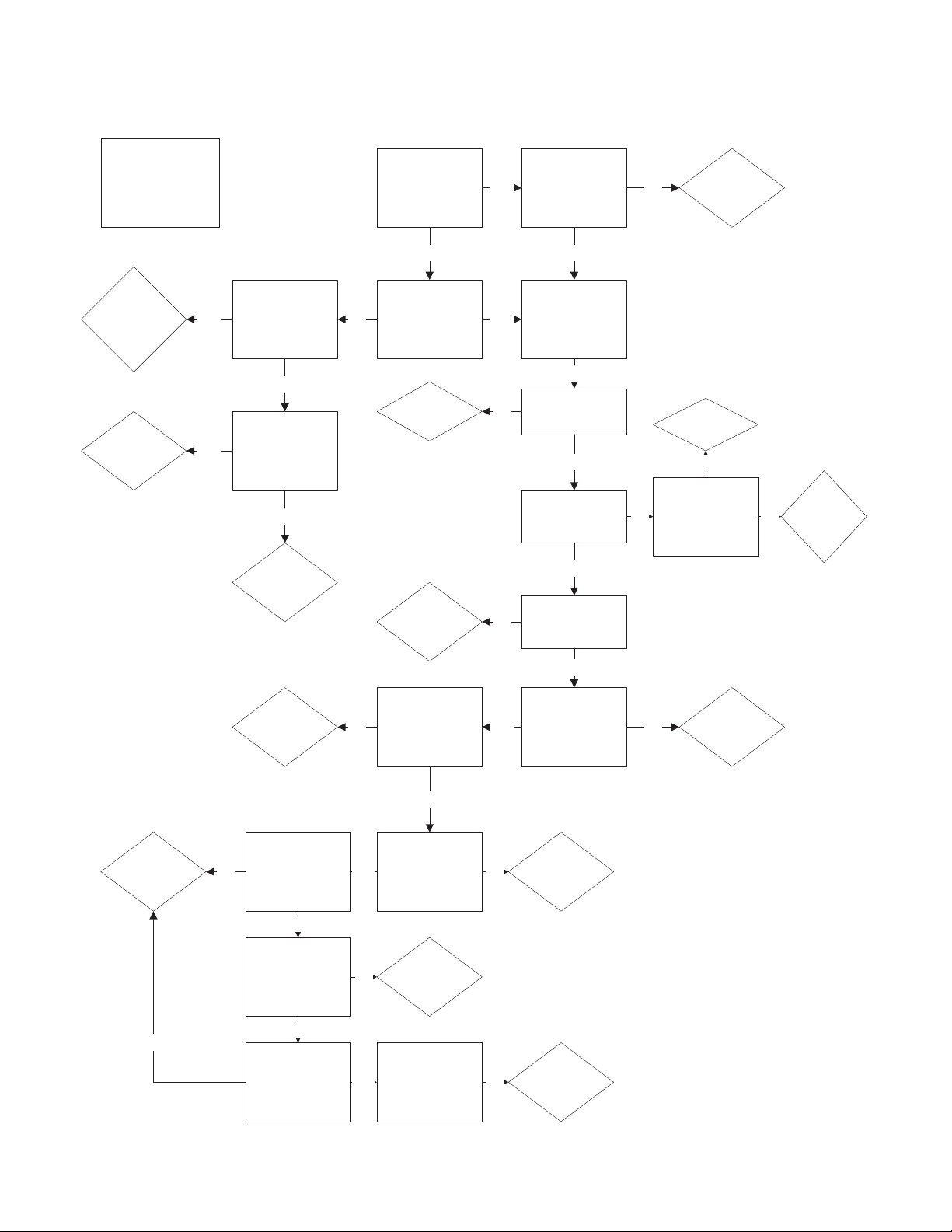
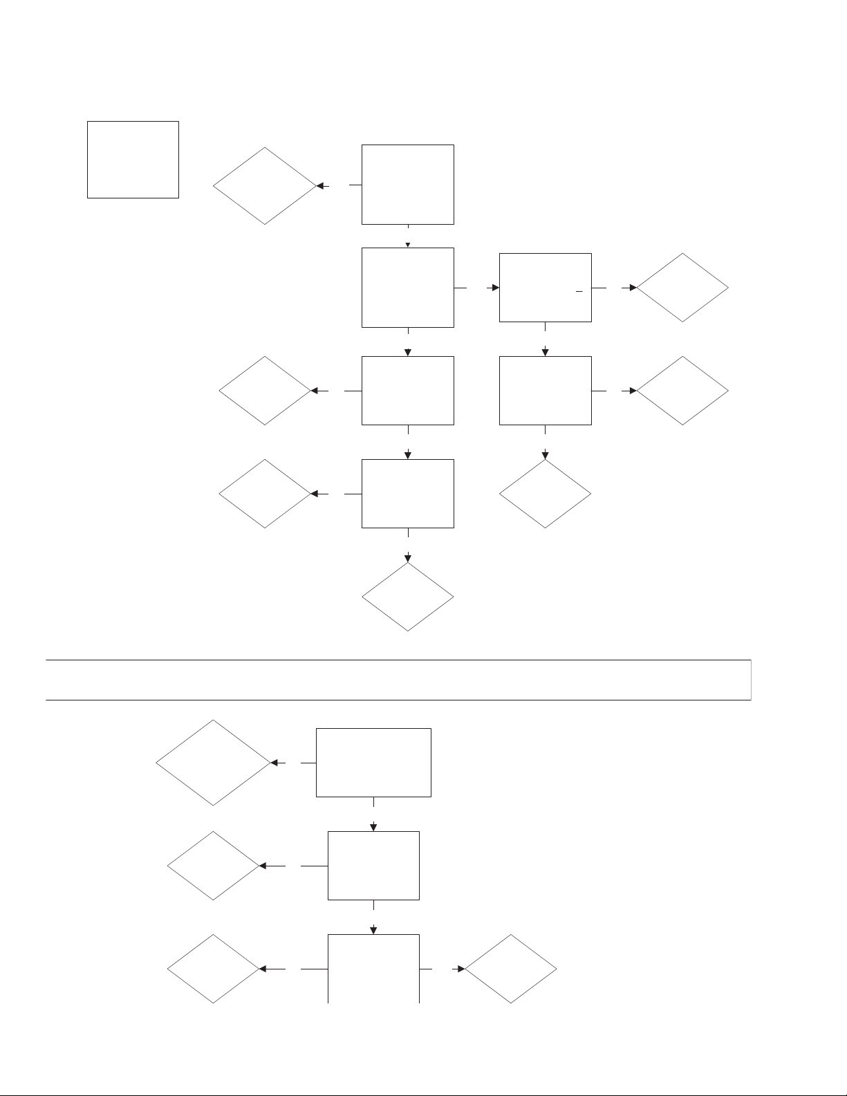
TROUBLESHOOTING GUIDES (continued)
PROBLEM:
KGL
Kettle Won't
Heat
Does red light
come on when unit
is first turned on?
Does red light go
off shortly after
unit is turned on?
Yes
Add water to
jacket of Kettle.
With the
potentiometer set
at 10, is 12 VDC at
the coil of the
relay?
No
Yes
Is 16 VAC
measured across
Pins 9 and 10 on
the controller?
No
Yes
Is 16 VAC at the
secondary side of
the transformer?
No
Replace
the on/off
switch (toggle
or rotary).
Yes
Is there Power to
the primary of the
transformer?
No
Replace the
transformer.
Yes
Supply power
to the kettle.
No
Does the relay pull
in?
Yes
Replace the
relay.
No
Is there power to
the blower?
Yes
With the high limit
temporarily
bypassed, is
power at the
blower?
No
Replace the
high limit.
Yes
Replace
the wire to
the blower.
No
Is there power to
the ignition
transformer?
Is there 24 VAC at
the secondary of
the ignition
transformer?
Is there 24 VAC to
the igniton
module?
Yes
Does the blower
turn?
Replace
blower.
No
Yes
Yes
Replace the
DC relay.
Replace the
ignition
transformer
Replace the air
switch.
No
Is there 120 VAC
to the igniter?
Yes
Replace
ignition
module.
No
Does the ignitor
glow?
Yes
Replace the
ignitor.
No
No
Does the gas
valve get 24 VAC
20 sec. after the
ignitor is
energized?
Yes
No
Does the gas
valve open?
Yes
Replace gas
valve
No
Yes No
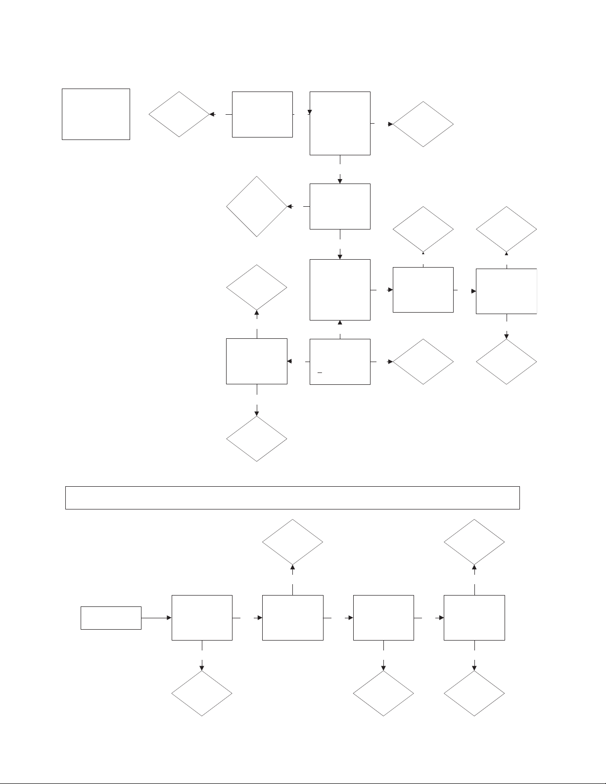
TROUBLESHOOTING GUIDES (continued)
PROBLEM:
KGL
Kettle Not
Hot Enough
W
ith kettle pot
empty and
temperature knob
s
et at 10, is the
t
emperature of the
surface of the pot
260 degrees?
U
nit is
operating
properly
Yes
W
hen unit is cold
(room temp) is the
p
ressure gauge in
the green?
N
o
V
ent
the kettle per
i
nstructions in
the manual.
N
o
When the unit is
calling for heat
(the green light is
on), is there flame
at the burner?
Y
es
I
s the resistance of
the thermister
100,000 ohms
+10% at room
temperature?
Yes
Replace the
thermister.
No
Is the
potentiometer
resistance 50,000
ohms at low and 0
ohms at high?
Yes
R
eplace
c
ontroller.
Yes
Replace the
potentiometer.
No
Does the kettle
h
eat at all?
Yes
See Problem:
K
ettle won't
h
eat.
No
Is the blower
turning?
Replace the
h
igh limit?
I
s there voltage to
the blower?
No
Y
es
N
o
Replace the
b
lower
No
Replace the air
switch
Y
es
PROBLEM: KGL Kettle Has Delayed Ignition
Delayed Igniton
Is the gas
pressure to the
burner 3.5" W.C.?
Adjust or
replace the gas
Valve.
Does the ignior
glow evenly
Replace ignitor.
No
Yes
No
Does the gas
valve get 24 VAC
20 seconds after
the ignitor is
energized?
Replace the
ignition
module.
Is the blower
turning?
Replace blower
and air switch.
Replace burner
Yes
No
Yes
No
Yes
TROUBLESHOOTING GUIDES (continued)
PROBLEM:
KGL Kettle
Gets Too
Hot
With the kettle
empty and the
temperature set at
10, is the surface
temp 260-265
degrees?
The
kettle is working
properly.
Yes
Does the kettle
continue to call for
heat (green light
stays on) when
the kettle reaches
260-265 degrees?
No
Is there supply
voltage to the coil
of the gas valve?
No
Replace the
gas valve.
No
Is there any DC
voltage to the coil
of the relay?
Replace the
Relay
Yes
Replace the
controller
Yes
No
Is the resistance of
;the thermister
1
00,000 ohms +
10% at room
temperature?
Yes
Replace the
thermister.
No
Is the resistance of
the potentiometer
50,000 ohms at
the low setting and
0 ohms at high?
Yes
Replace the
controller
Replace the
potentiometer
No
Yes
PROBLEM: Red Add Water LED Stays On
Does Red LED stay on
after adding the proper
amount of distilled
water and rust inhibitor?
Add the proper
amount of distilled
water and rust
inhibitor.
No
Is the red LED on
with probe
grounded?
Yes
Clean or
replace water
probe.
No
Does the red LED
stay on with a
jumper between
pins 5 and 7 on
the controller?
Yes
Replace the
wire harness in
the trunion.
No
Replace the
controller.
Yes
KETTLE SAFETY INSPECTION AND TESTING
260º - 270º
MAXIMUM
KETTLE
TEMPERATURE
265º
✔
2
3
5
6
7
8
9
1
4
10
OFF
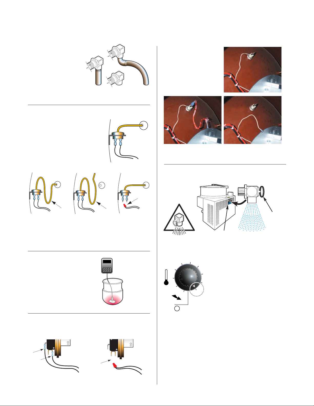
!
SAFETY VALVE
INSTALLATION:
The above illustrations show
the three variations of factory
installed Safety Valves.
Modifications are unacceptable.
SAFETY THERMOSTAT:
Correct
Installation
Incorrect
Installations
1.
2.
P
robe
fully
inserted
i
n tube
Wiring is properly
connected
3.
LOW WATER
LEVEL PROBE:
Probe
p
Probe bypassed by
running (A) an
✘
additional wire
roperly
attached
✔
Probe bypassed by
(B) grounding the
✘
connecting wire
PRESSURE RELIEF VALVE TESTING
Probe removed
partially
1.
Safety thermostat probe is not completely inserted into tubing.
2. Safety thermostat probe is removed from tubing.
3. Safety thermostat electrical connection is bypassed.
Probe removed
completely
OPERATING
THERMOSTAT:
If maximum temperature is not
in this range (on empty kettle),
refer to the “Calibrating
Procedure”.
GAS KETTLE AIR SWITCH:
Correct Incorrect
Wiring is properly connected Switch electrically bypassed
Thermostat
electrically bypassed
260° - 270° F
MAXIMUM
KETTLE
TEMPERATURE
Access
Panel
WARNING:
personal injury.
Pull Pressure Relief Valve Ring open for a maximum of
4.
one second. Repeat test three to four times. Each time
the mechanism should move freely and be
accompanied by a rapid escape of steam.
5.
Replace access panel.
IMPORTANT:
If valve appears to be sticking replace pressure relief
valve.
If foreign material is discharged then drain kettle and
replace pressure relief valve.
Use of gloves and eye protection to prevent
1. With the kettle empty, set On-
Off Switch/Temperature Control
to "10" (Max.). Allow the kettle
to heat until the unit cycles off.
Switch On-Off Switch/Temperature
2.
Control to
main power at fused disconnect
switch.
3. Remove Access Panel at back
of main kettle console.
"0"
(Off) and disconnect
Pressure
Relief
Valve
Ring
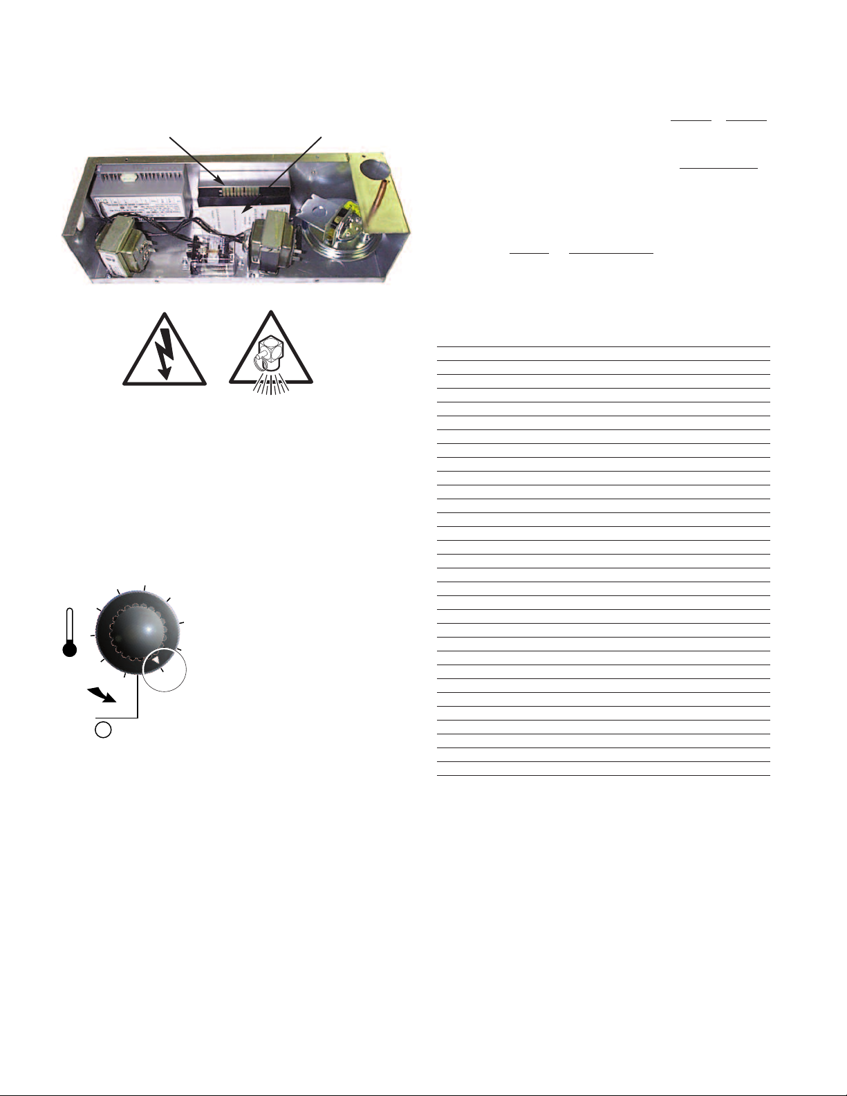
CALIBRATING PROCEDURE FREE AIR CALCULATION
2
3
5
6
7
8
9
1
4
10
OFF
0
!
!
Insert drager pump tube 4" down the center
olid State Temperature
S
ontrol Box
C
djustment
A
ot
P
of the flue and take one sample each of
Carbon Dioxide (CO2) and Carbon
Monoxide (CO) and record results.
With results obtained for CO2 use chart to
determine dilution factor for gas type used.
Enter these numbers in the following formula
to determine the concentration of carbon
monoxide in an air free sample of flue gas.
_____________
_
CO
%
PPM)
(
__________________________
_
ilution Factor
D
______________
CO2
%
1. Insure the unit has a vacuum before you begin
calibrating procedures. If unit requires venting refer to
KETTLE VENTING INSTRUCTIONS.
Set On-Off Switch/Temperature Control to "10"(Max.).
2.
3. Allow the unit to cycle twice.
4. Check temperature of the inner kettle surface with a
digital surface thermometer.
5. Temperature should be between 260°F and 265°F.
6. Using a screw driver
adjust temperature by
turning the potentiometer
on the Solid State
Temperature Control Box.
Turn very little. Turn
clockwise to INCREASES
and counter-clockwise to
DECREASE temperature.
7. Allow the unit to cycle
twice.
8. Check temperature of the
inner kettle surface with a
digital surface
thermometer.
9. Repeat steps 4. through 8. until unit is calibrated.
Dilution Factor X CO (PPM) =
0,000
1
_____________________________
% Carbon Monoxide
Result must not exceed 0.08% carbon monoxide.
CARBON DIOXIDE IN FACTOR FACTOR
SAMPLE (PERCENT) PROPANE GAS NATURAL GAS
4.0 3.50 3.05
4.2 3.33 2.90
4.4 3.18 2.77
4.6 3.04 2.65
4.8 2.92 2.54
5.0 2.80 2.44
5.2 2.69 2.34
5.4 2.59 2.26
5.6 2.50 2.18
5.8 2.41 2.10
6.0 2.33 2.03
6.2 2.26 1.97
6.4 2.19 1.91
6.6 2.12 1.85
6.8 2.06 1.80
7.0 2.00 1.74
7.2 1.94 1.70
7.4 1.89 1.65
7.6 1.84 1.61
7.8 1.79 1.56
8.0 1.75 1.53
8.2 1.71 1.49
8.4 1.67 1.45
8.6 1.63 1.42
8.8 1.59 1.39
9.0 1.56 1.36
9.2 1.52 1.33
9.4 1.49 1.30
9.6 1.46 1.27
9.8 1.43 1.24
10.0 1.40 1.22
 Loading...