

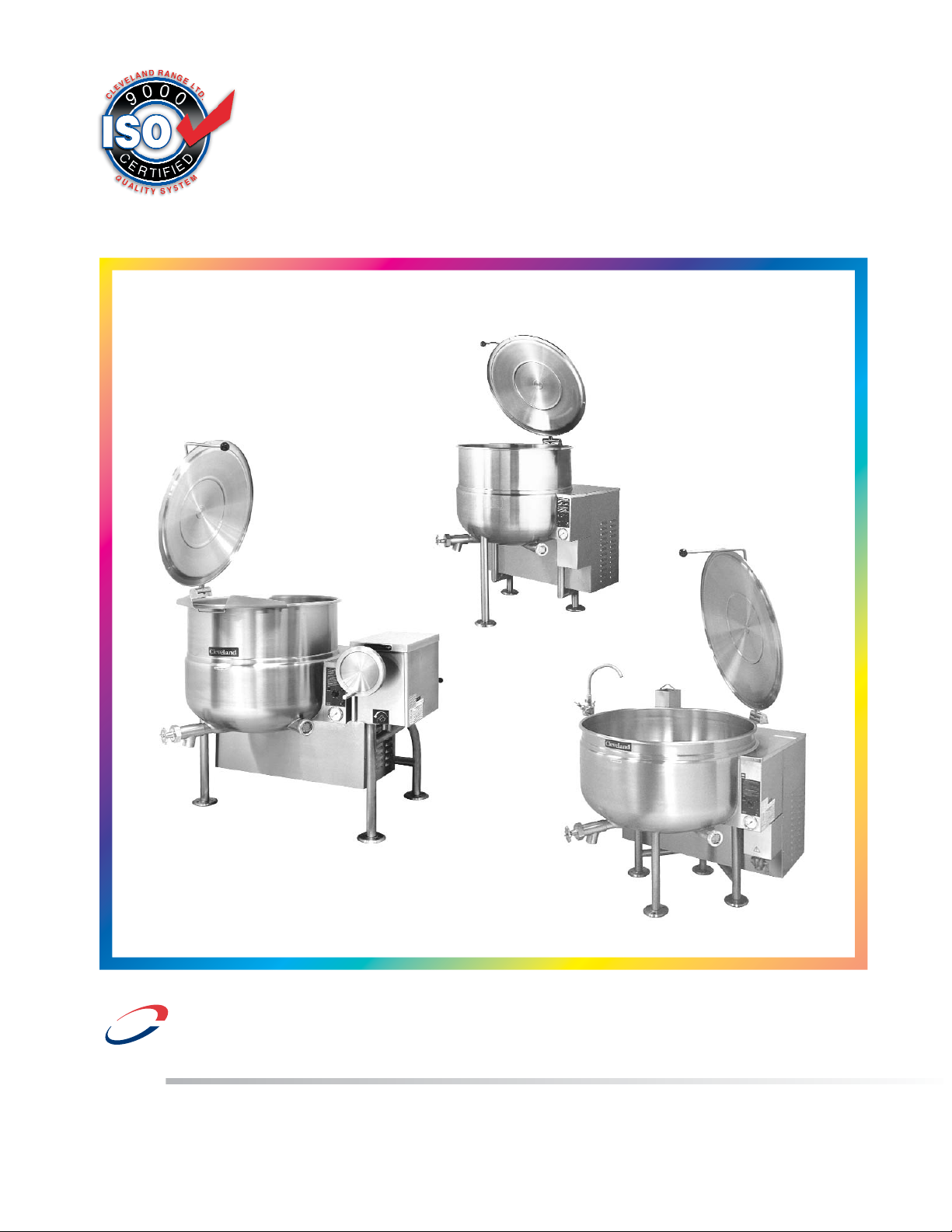
Operators Manual
Installation, Operation & Service
Gas Floor Model Kettles
MODELS:
Stationary - KGL-40, KGL-60, KGL-80, KGL-100
Tilting - KGL-40-T, KGL-60-T, KGL-80-T
Short Series - KGL-40-SH, KGL-60-SH,
KGL-40-TSH
KGL-40
KGL-40-T
KGL-40SH
SE95003-1 Rev. 6
1333 East 179th St., Cleveland, Ohio, U.S.A. 44110
Phone: (216) 481-4900 Fax: (216) 481-3782
Visit our web site at www.clevelandrange.com
d
Enodis
™
Clev elan
FOR THE USER
WARNING: Improper installation,
adjustment, alteration, service or
maintenance can cause property
damage, injury or death. Read the
installation and operating
instructions thoroughly before
installing or servicing this
equipment.
FOR YOUR SAFETY
DO NOT STORE OR USE GASOLINE
OR ANY OTHER
FLAMMABLE LIQUIDS AND
VAPOURS IN THE VICINITY
OF THIS OR ANY OTHER
APPLIANCE.
IMPORTANT!
PRIOR TO REMOVING ANY FITTINGS ENSURE KETTLE IS AT
ROOM TEMPERATURE AND
PRESSURE GAUGE IS SHOWING ZERO OR LESS PRESSURE.
.
IMPORT
ANT
The following points are to insure the safe installation and operation of this equipment:
• Insure all gas and electrical supplies match rating plate and electrical stickers.
• Observe all clearance requirements.
• Disconnect the electrical power supply to the appliance before cleaning or servicing unit.
• All service must be performed by a qualified Cleveland Range Technician.
• Do not obstruct the flow of combustion and ventilation air.
The installation and connection must comply with current local codes, or in the absence of local codes, with
CAN/CGA-B149.1 and .2 installation code or with the national fuel gas code, ANSI Z223.1-L988.
Post in a prominent location, instructions to be followed in the event the user smells gas. This information shall
be obtained by consulting your local gas supplier.
The appliance and its individual shut off valve must be disconnected from the gas supply piping system during
any pressure testing of that system at test pressures in excess of 1/2 psig. (3.45 kpa).
The appliance must be isolated from the gas supply piping system by closing its individual manual shut off
valve during any pressure testing of the gas supply piping system at test pressures equal to or less than 1/2
psig. (3.45 kpa).
RETAIN THIS MANUAL FOR YOUR REFERENCE.
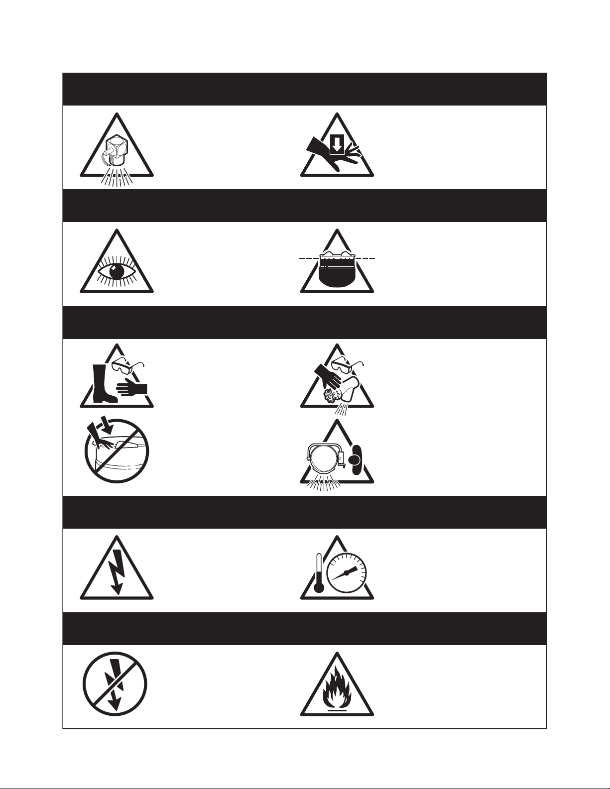
For your safety
DANGER
Keep clear of pressure
relief discharge.
IMPORTANT
Inspect unit daily for
proper operation.
CAUTION
Surfaces may be
extremely hot! Use
protective equipment.
Keep hands away from
moving parts and pinch points.
Do not fill kettle above
recommended level
marked on outside of kettle.
Wear protective equipment
when discharging hot product.
Do not lean on or place
objects on kettle lip.
SERVICING
Shut off power at main
fuse disconnect prior
to servicing.
GAS APPLIANCES
Do not attempt to operate
this appliance during a
power failure.
Stand clear of product
discharge path when
discharging hot product.
Ensure kettle is at room
0
temperature and pressure
gauge is showing zero or less
prior to removing any fittings.
Keep appliance and area free
and clear of combustibles.

INSPECTION
Before unpacking visually inspect the unit for evidence
of damage during shipping.
If damage is noticed, do not unpack the unit, follow
shipping damage instructions.
SHIPPING DAMAGE
INSTRUCTIONS
If shipping damage to the unit is discovered or
suspected, observe the following guidelines in
preparing a shipping damage claim.
1. Write down a description of the damage or the
reason for suspecting damage as soon as it is
discovered. This will help in filling out the claim
forms later.
2. As soon as damage is discovered or suspected,
notify the carrier that delivered the shipment.
3. Arrange for the carrier's representative to examine
the damage.
4. Fill out all carrier claims forms and have the
examining carrier sign and date each form.
GENERAL
Installation of the kettle must be accomplished by
qualified installation personnel working to all applicable
local and national codes. Improper installation of
product could cause injury or damage.
This equipment is built to comply with applicable
standards for manufacturers. Included among those
approval agencies are: UL, A.G.A., NSF, ASME/N.Bd.,
CSA, CGA, ETL, and others. Many local codes exist,
and it is the responsibility of the owner/installer to
comply with these codes.
Observe all clearance requirements to provide proper
make-up air flow. Do not obstruct the flow of combustion
and ventilation air. Check rating plate to ensure that
kettle has been equipped to operate with the type of
gas available at the installation.
VENTILATION
Gas fired kettles are only to be installed under a
ventilation hood in a room which has provisions for
adequate make up air. Further information can be
obtained by referring to the U.S.A. National Fire
Protection Associations NFPA96 regulations. These
standards have also been adopted by the National
Building Code in Canada.
CLEARANCE REQUIREMENTS
This unit must be installed in accordance with the
clearances shown on the rating label which is adhered
to the unit.
FOR YOUR SAFETY. Keep the appliance area free and
clear of combustible materials.
INSTALLATION
1. Position the unit in it's permanent location, and level
the unit by turning the adjustable feet.
2. Once positioned and leveled, permanently secure
the unit's flanged
feet to the floor
using 5/16" lag
bolts and floor
anchors (supplied
by the installer).
Three bolts are
required to secure
each of the
flanged feet.
3. Seal joints of flanged feet with a silicone sealant.
GAS
ENSURE THE GAS SUPPLY MATCHES THE
KETTLE'S REQUIREMENTS AS STATED ON THE
RATING PLATE.
It is recommended that a sediment trap (drip leg) be
installed in the gas supply line. If the gas pressure
exceeds 14” water column, a pressure regulator must
be installed, to provide a maximum of 14” water column
gas pressure to the gas control valve.
Connect the gas line to the manual valve located at the
rear of the control box.
Installation must be in accordance with local codes
and/or the National Fuel Gas Code ANSI Z223.1 Latest
Edition (USA) or the latest Installation Codes for Gas
Burning Appliances and Equipment CAN/ CGA B149.1
and CAN/ CGA B149.2 (Canada). Use a gas pipe joint
compound which is resistant to L.P. gas. Test all pipe
joints for leaks with soap and water solution. Ensure that
the gas pressure regulator is set for the manifold
pressure indicated on the gas rating plate.
The appliance and its individual shut-off valve must be
disconnected from the gas supply piping system during
any pressure testing of that system at test pressures in
excess of 1/2 psi (3.45 kPa). The appliance must be
isolated from the gas supply piping system by closing
its individual manual shut-off valve during any pressure
testing of the gas supply piping system at test
pressures equal to or less than 1/2 psi (3.45 kPa).
INSTALLATION
FLANGED FOOT DETAIL
4 7/8" (124mm)
120 120
7/16"Ø, 3 HOLES
ON 3 1/8" (80mm) B.C.D.
(REAR LEGS ONLY)

ELECTRICAL
ENSURE THE ELECTRICAL SUPPLY MATCHES THE
KETTLE'S REQUIREMENTS AS STATED ON THE
RATING LABEL.
A cord and plug are supplied with the unit. Simply plug
the unit into any grounded outlet rated for a minimum of
10 amps. The wiring diagram is located under the cover
of electrical box inside the back console.
WARNING: Electrical Grounding Instructions.
This unit is equipped with a three-prong (grounding)
plug for your protection against shock hazard and
should be plugged directly into a properly grounded
three-prong receptacle. Do not cut or remove the
grounding prong from this plug. Standard supply
voltage is 115 volts A.C., however, optional A.C.
voltages can be supplied on special order. A separate
fused disconnect switch must be supplied and installed
in the high voltage electrical supply line. The kettle must
be electrically installed and grounded in accordance
with local codes, or in the absence of local codes, with
National Electrical Code, ANSI/NFPA 70-1990 (USA) or
the Canadian Electrical Code, CSA C22.2, Part 1
(Canada).
WATER
The sealed jacket of the gas-fired kettle is precharged
with the correct amount of a water-based formula, and
therefore, no water connection is required to the kettle
jacket. The kettle can be equipped with optional hot and
cold water taps, requiring 1/2" copper tubing as supply
lines.
CLEANING
After installation the kettle must be thoroughly cleaned
and sanitized prior to cooking.
INSTALLATION CHECKS
Although the kettle has been thoroughly tested before
leaving the factory, the installer is responsible for
ensuring the proper operation of kettle once installed.
DO NOT ATTEMPT TO OPERATE THIS APPLIANCE
DURING A POWER FAILURE.
KEEP APPLIANCE AND AREA FREE AND CLEAR OF
COMBUSTIBLES.
1. Before turning the kettle on, read the
vacuum/pressure gauge. The gauge's needle
should be in the green zone. If the needle is in the
"VENT AIR" zone, follow air venting procedure.
2. Unit has been thoroughly checked for gas leaks at
the factory however the installer should check all
connections using soap bubble or gas detector for
any leaks which may have resulted from shipping or
installation.
3. Supply power to the kettle by placing the fused
disconnect switch to the "ON" position.
4. Open gas shut-off valve to turn on main gas supply..
5. Turn the temperature control knob to "1" (Min.). The
green LED light should remain lit, indicating the burner
is lit, until the set temperature is reached. Then the
green light will cycle on and off, indicating the burner
is cycling on and off to maintain temperature.
6. Tilt the kettle forward. After a few seconds the red
"LOW WATER" light should be lit when the kettle is in
a tilted position. This light indicates that the burner
has automatically been shut off by the kettle's safety
circuit. This is a normal condition when the kettle is
in a tilted position.
7. Raise the kettle to the upright position. The red
"LOW WATER" light should go out when the kettle is
upright.
8. Turn the temperature control knob to "10" (Max.) and
allow the kettle to preheat. The green light should
remain on until the set temperature is reached. Then
the green light will cycle ON and OFF, indicating the
burner is cycling ON and OFF to maintain
temperature.
OPERATING INSTRUCTIONS
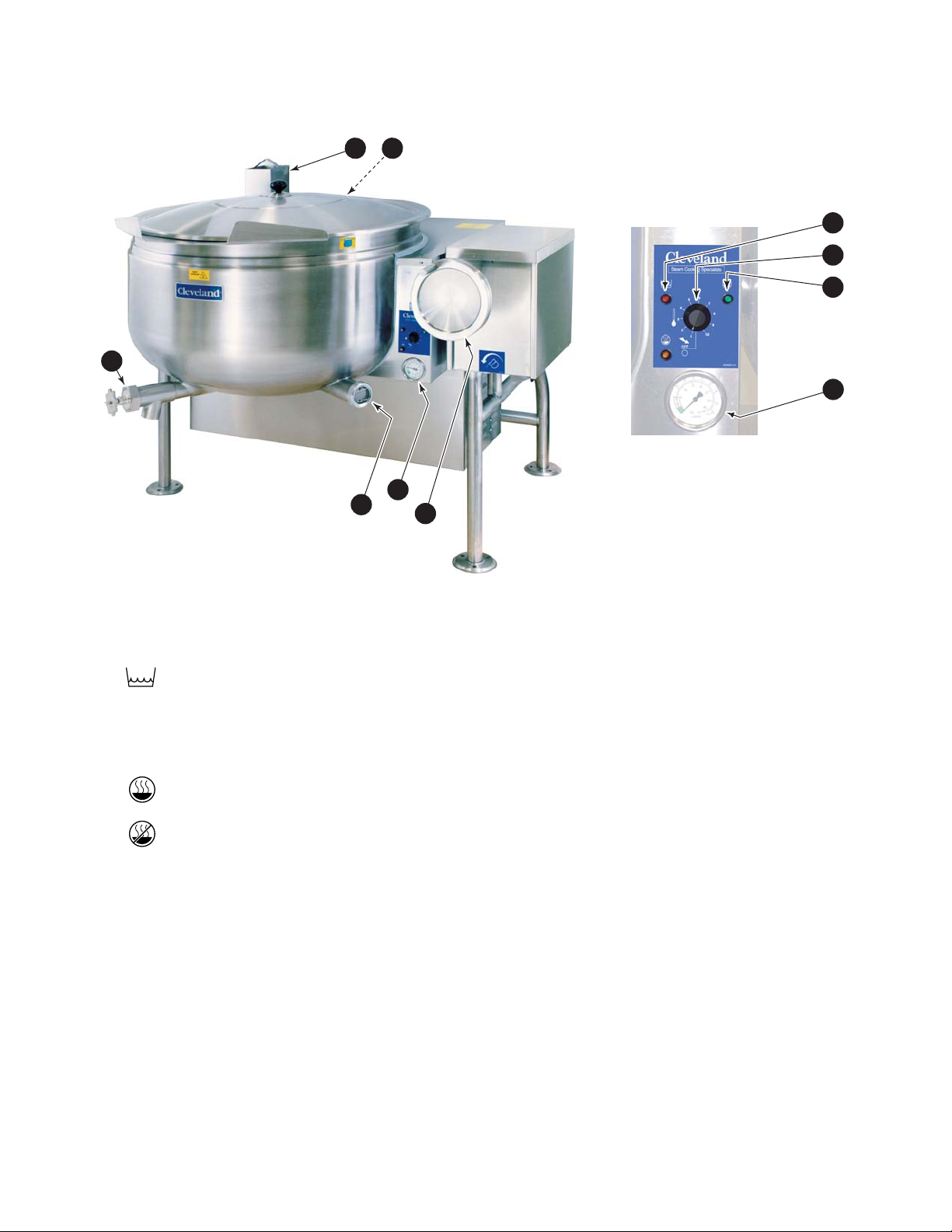
ITEM # DESCRIPTION FUNCTION
1. Low Water Indicator Light (Red) When lit, indicates that the kettle is low on water and will not operate
in this condition. This will also light when the kettle is in the tilted
position.
2. On-Off Switch/ Turns kettle ON/OFF and allows the operator to adjust the kettle
Solid State temperature in increments from 1 (Min.) to 10 (Max.).
Temperature Control (see the TEMPERATURE RANGE CHART).
3. Heat Indicator Light (Green) When lit, indicates that the kettle's burner is on.
Cycles ON-OFF with burner.
4. Vacuum/Pressure Gauge Indicate steam pressure in PSI inside steam jacket as well as
vacuum in inches of mercury.
5. Pressure Relief Valve This valve is used to vent the kettle and in the unlikely event there is
(not shown) an excess steam build-up in the jacket, this valve opens
automatically to relieve this pressure.
6. Water Level Sight Glass Displays water level in steam jacket.
7. Tilt Wheel Used for tilting the kettle on hand tilt models. In power tilt models
there is a toggle switch in same location.
8. Flue
9. Tangent Draw-Off Valve Used for draining product or wash water from kettle. It is supplied as
standard equipment on stationary kettles and is optional on tilting kettles
.
Operating Controls & Indicators
8 5
9
4
6
7
1
2
3
4
OPERATING THE KETTLE
DO NOT ATTEMPT TO OPERATE
THIS APPLIANCE DURING A POWER
FAILURE.
KEEP APPLIANCE AND AREA FREE
AND CLEAR OF COMBUSTIBLES.
DO NOT LEAN ON OR PLACE OBJECTS ON KETTLE
LIP. SERIOUS INJURY COULD RESULT IF KETTLE
TIPPED OVER, SPILLING HOT CONTENTS.
IF YOU ARE COOKING AN EGG OR MILK
PRODUCT, DO NOT PRE-HEAT KETTLE.
1. Before turning kettle on, read the Vacuum/Pressure
Gauge (5). The gauges needle should be in the
green zone. Once heated, the kettle's normal
maximum operating pressure is approximately 10 12 psi while cooking a water base product.
2. Ensure that the electrical service to the kettle is
turned on at the fused disconnect switch.
Temperature Range Chart
3. Preheat the kettle by turning the
ON/OFF
Switch/Solid State Temperature Control
(2) to the
desired temperature setting (see above
"Temperature Range Chart"). The Heat Indicator
Light (Green) (3) will remain lit, indicating the
burner is on, until the temperature setting is
reached. When the green light goes off, the
burners are off, and preheating is complete.
NOTE: When cooking egg and milk products, the kettle
should not be preheated, as products of this nature adhere to
hot cooking surfaces. These types of food should be placed in
the kettle before heating is begun.
4. Place food product into the kettle. The green Heat
Indicator Light (3) will cycle on and off indicating
the burners are cycling on and off to maintain the
set temperature.
NOTE: Do not fill kettle above
recommended level marked on outside
of kettle.
NOTE: The Low Water Indicator Light (Red) (1) should not
be lit during kettle operation. This light indicates that the
burners have been automatically shut off by the kettle's safety
circuit. It is normal for the red light to come on when the kettle
is in a tilted position..
5. When cooking is completed turn
On/Off Switch/Solid
State Temperature Control
(2) to the "OFF' position.
NOTE: A five minute complete shut-of period is
required before relighting.
6. Pour the contents of the kettle into an appropriate
container by tilting the kettle forward. Care should
be taken to pour slowly enough to avoid splashing
off the product.
NOTE: As with cleaning food soil from any cookware, an
important part of kettle cleaning is to prevent food from
drying on. For this reason, cleaning should be completed
immediately after cooked foods are removed. Refer to the
Cleaning Instructions for detailed kettle washing
procedures.
APPROXIMATE BOILING TIMES
The accompanying chart shows approximate times
required for gas kettles of various capacities to boil
water with the lid open. The
ON/OFF Switch/Solid State
Temperature Control
(2) must be set at “10” throughout
the heat-up period. Water will boil about 1/3 faster if the
kettle is filled only to the outer steam jacket’s welded
seam resulting in a kettle filled to 2/3 capacity.
Approximate Boiling Times
Kettle Capacity Minutes
KGL, KGL-T
40 gallon 35
60 gallon 47
80 gallon 60
100 gallon 75
KGL-SH, KGL-TSH
60 gallon 27
80 gallon 34
Temperature Approximate
Control Product Temperature
Setting °F °C
1. 120 49
2. 135 57
3. 150 66
4. 165 74
5. 180 82
6. 195 91
7. 210 99
8. 225 107
9. 245 118
10. 265 130
NOTE: Certain combinations of ingredients will
result in temperature variations
!
CARE AND CLEANING
Cooking equipment must be cleaned regularly to
maintain its fast, efficient cooking performance and
to ensure its continued safe, reliable operation. The
best time to clean is shortly after each use (allow
unit to cool to a safe temperature).
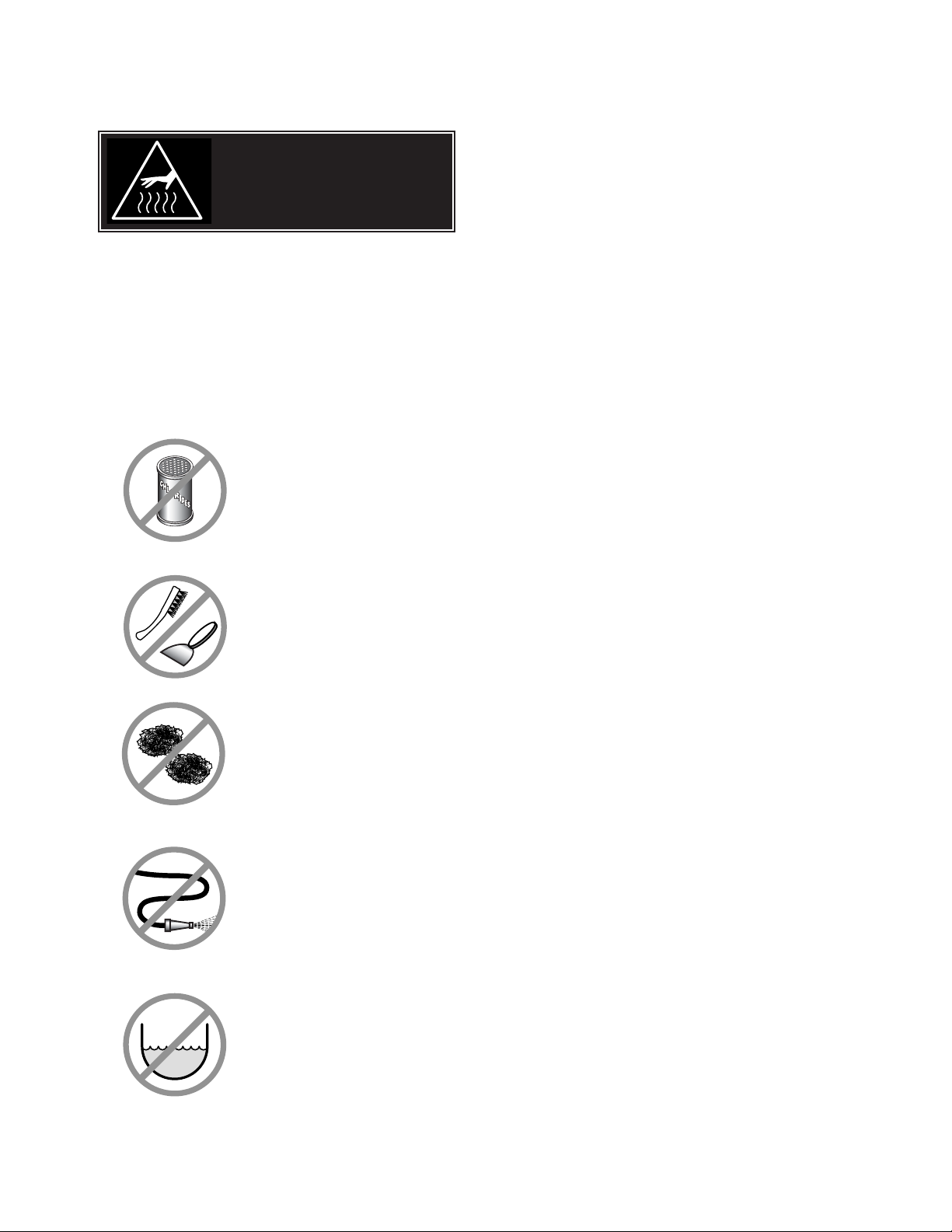
WARNINGS
➩ Do not use detergents or
cleansers that are chloride
based or contain quaternary
salt.
➩ Do not use a metal bristle
brush or scraper.
➩ Steel wool should never be
used for cleaning the stainless
steel.
➩ Unit should never be cleaned
with a high pressure spray
hose.
➩
Do not leave water sitting in unit
when not in use.
CLEANING INSTRUCTIONS
CAUTION
SURFACES MAY
BE EXTREMELY HOT!
CLEANING INSTRUCTIONS
1. Turn unit off.
2. Remove drain screen (if applicable). Thoroughly
wash and rinse the screen either in a sink or a
dishwasher.
3. Prepare a warm water and mild detergent solution in
the unit.
4. Remove food soil using a nylon brush.
5. Loosen food which is stuck by allowing it to soak at
a low temperature setting.
6. Drain unit.
7. Rinse interior thoroughly.
8. If the unit is equipped with a
TTaannggeenntt DDrraaww--OOffff
VVaallvvee
, clean as follows:
a) Disassemble the draw-off valve first by turning
the valve knob counter-clockwise, then turning
the large hex nut counter-clockwise until the
valve stem is free of the valve body.
b) In a sink, wash and rinse the inside of the valve
body using a nylon brush.
c)
Use a nylon brush to clean tangent draw-off tube.
d) Rinse with fresh water.
e) Reassemble the draw-off valve by reversing the
procedure for disassembly. The valve's hex nut
should be hand tight only.
9. If the unit is equipped with a
BBuutttteerrffllyy VVaallvvee
, clean
as follows:
a) Place valve in open position.
b) Wash using a warm water and mild detergent
solution.
c) Remove food deposits using a nylon brush.
d) Rinse with fresh water.
e) Leave valve open when unit is not in use.
10 . Using mild soapy water and a damp sponge, wash
the exterior, rinse, and dry.
NOTES
➩ For more difficult cleaning applications one of the
following can be used: alcohol, baking soda, vinegar,
or a solution of ammonia in water.
➩ Leave the cover off when the kettle is not in use.
➩ For more detailed instructions refer to the Nafem
Stainless Steel Equipment Care and Cleaning manual
(supplied with unit).
Chloride Cleaners
Wire Brush &
Steel Pads
High Pressure
Spray Hose
Stagnant
Water

STAINLESS STEEL EQUIPMENT CARE AND CLEANING
(Supplied courtesy of Nafem. For more information visit their web site at www.nafem.org)
Contrary to popular belief, stainless steels ARE susceptible to rusting.
Corrosion on metals is everywhere. It is recognized quickly on iron and
steel as unsightly yellow/orange rust. Such metals are called “active”
because they actively corrode in a natural environment when their atoms
combine with oxygen to form rust.
Stainless steels are passive metals because they contain other metals, like
chromium, nickel and manganese that stabilize the atoms. 400 series
stainless steels are called ferritic, contain chromium, and are magnetic;
300 series stainless steels are called austenitic, contain chromium and
nickel; and 200 series stainless, also austenitic, contains manganese,
nitrogen and carbon. Austenitic types of stainless are not magnetic, and
generally provide greater resistance to corrosion than ferritic types.
With 12-30 percent chromium, an invisible passive film covers the steel’s
surface acting as a shield against corrosion. As long as the film is intact
and not broken or contaminated, the metal is passive and stain-less. If the
passive film of stainless steel has been broken, equipment starts to
corrode. At its end, it rusts.
Enemies of Stainless Steel
There are three basic things which can break down stainless steel’s
passivity layer and allow corrosion to occur.
1. Mechanical abrasion
2. Deposits and water
3. Chlorides
Mechanical abrasion means those things that will scratch a steel surface.
Steel pads, wire brushes and scrapers are prime examples.
Water comes out of the faucet in varying degrees of hardness. Depending
on what part of the country you live in, you may have hard or soft water.
Hard water may leave spots, and when heated leave deposits behind that
if left to sit, will break down the passive layer and rust stainless steel. Other
deposits from food preparation and service must be properly removed.
Chlorides are found nearly everywhere. They are in water, food and table
salt. One of the worst chloride perpetrators can come from household and
industrial cleaners.
So what does all this mean? Don’t Despair!
Here are a few steps that can help prevent stainless steel rust.
1.
Use the proper tools.
When cleaning stainless steel products, use non-abrasive tools. Soft
cloths and plastic scouring pads will not harm steel’s passive layer.
Stainless steel pads also can be used but the scrubbing motion must
be in the direction of the manufacturers’ polishing marks.
2.
Clean with the polish lines.
Some stainless steel comes with visible polishing lines or “grain.”
When visible lines are present, always scrub in a motion parallel to the
lines. When the grain cannot be seen, play it safe and use a soft cloth
or plastic scouring pad.
3.
Use alkaline, alkaline chlorinated or non-chloride containing cleaners.
While many traditional cleaners are loaded with chlorides, the industry
is providing an ever-increasing choice of non-chloride cleaners. If you
are not sure of chloride content in the cleaner used, contact your cleaner
supplier. If your present cleaner contains chlorides, ask your supplier if
they have an alternative. Avoid cleaners containing quaternary salts; it
also can attack stainless steel and cause pitting and rusting.
4.
Treat your water.
Though this is not always practical, softening hard water can do much
to reduce deposits. There are certain filters that can be installed to
remove distasteful and corrosive elements. To insure proper water
treatment, call a treatment specialist.
5.
Keep your food equipment clean.
Use alkaline, alkaline chlorinated or non-chloride cleaners at
recommended strength. Clean frequently to avoid build-up of hard,
stubborn stains. If you boil water in stainless steel equipment,
remember the single most likely cause of damage is chlorides in the
water. Heating cleaners that contain chlorides have a similar effect.
6.
Rinse, rinse, rinse.
If chlorinated cleaners are used, rinse and wipe equipment and
supplies dry immediately. The sooner you wipe off standing water,
especially when it contains cleaning agents, the better. After wiping
equipment down, allow it to air dry; oxygen helps maintain the
stainless steel’s passivity film.
7.
Never use hydr
ochloric acid (muriatic acid) on stainless steel.
8.
Regularly restore/passivate stainless steel.
Recommended cleaners for specific situations
Job Cleaning Agent Comments
Routine cleaning Soap, ammonia, Apply with cloth or sponge
detergent, Medallion
Fingerprints & smears Arcal 20, Lac-O-Nu Provides barrier film
Ecoshine
Stubborn stains & Cameo, Talc, Zud, Rub in direction of polish lines
discoloration First Impression
Grease & fatty acids, Easy-off, De-Grease Excellent removal on all finishes
blood, burnt-on-foods It Oven Aid
Grease & oil Any good Apply with sponge or cloth
commercial detergent
Restoration/Passivation Benefit, Super Sheen
Review
1. Stainless steels rust when passivity (film-shield) breaks down as a
result of scrapes, scratches, deposits and chlorides.
2. Stainless steel rust starts with pits and cracks.
3. Use the proper tools. Do not use steel pads, wire brushes or scrapers
to clean stainless steel.
4. Use non-chlorinated cleaners at recommended concentrations. Use
only chloride- free cleaners.
5. Soften your water. Use filters and softeners whenever possible.
6. Wipe off cleaning agent(s) and standing water as soon as possible.
Prolonged contact causes eventual problems.
To learn more about chloride-stress corrosion and how to prevent it,
contact the equipment manufacturer or cleaning materials supplier.
Developed by Packer Engineering, Naperville, Ill., an independent testing
laboratory.
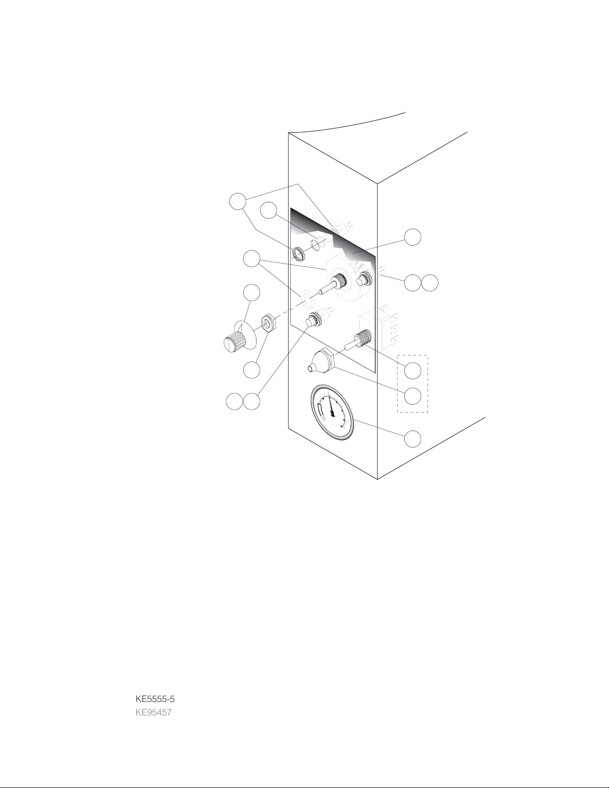
CONSOLE
CONTROLS
ITEM NO. PART NO. DESCRIPTION QTY.
1. KE50504 SWITCH, TOGGLE (USED PRIOR TO JANUARY 2000) . . . . . . . . . . . . . . . . . . .1
2. SK50062 RUBBER BOOT (USED PRIOR TO JANUARY 2000) . . . . . . . . . . . . . . . . . . . . .1
3. SE00114 POTENTIOMETER WITH ON/OFF SWITCH, C/W ITEM #4 . . . . . . . . . . . . . . . . .1
KE50988-2 POTENTIOMETER (USED PRIOR TO JANUARY 2000) . . . . . . . . . . . . . . . . . . .1
4. KE51005 RUBBER BOOT . . . . . . . . . . . . . . . . . . . . . . . . . . . . . . . . . . . . . . . . . . . . . . . . . .1
5. KE50569-1 KNOB, POTENTIOMETER . . . . . . . . . . . . . . . . . . . . . . . . . . . . . . . . . . . . . . . . . .1
6. SE003013-1 L.E.D., RED, Replacement Kit., (includes LED & "O" Ring) . . . . . . . . . . . . . . . .1
7. SE003013-2 L.E.D., GREEN, Replacement Kit., (includes LED & "O" Ring) . . . . . . . . . . . . . .1
8. SE003013-3 L.E.D., AMBER (Used prior to July 2004), Replacement Kit.,
(includes LED & "O" Ring) . . . . . . . . . . . . . . . . . . . . . . . . . . . . . . . . . . . . . . . . . .1
9. FA05002-18 "O" RING . . . . . . . . . . . . . . . . . . . . . . . . . . . . . . . . . . . . . . . . . . . . . . . . . . . . . . .3
10. KE50429-2 PRESSURE GAUGE . . . . . . . . . . . . . . . . . . . . . . . . . . . . . . . . . . . . . . . . . . . . . .1
11. KE5555-5 LABEL . . . . . . . . . . . . . . . . . . . . . . . . . . . . . . . . . . . . . . . . . . . . . . . . . . . . . . . . .1
KE95457 LABEL (USED PRIOR TO JANUARY 2000) . . . . . . . . . . . . . . . . . . . . . . . . . . . .1
SERVICE PARTS
KE95555-5
6
9
11
3
7 9
5
4
100
150
50
20
0
20
10
0
98
30
250
0
R
I
A
T
40
N
E
300
V
50
35
60
0
psi
400
k
P
a
USED
1
PRIOR
TO
JANUARY
2000
2
10
ELECTRICAL
COMPONENT
BOX
ITEM ON. PART NO. DESCRIPTION QTY.
KE01422 ELECTRICAL CONTROL BOX ASSEMBLY . . . . . . . . . . . . . . . . . . . . . . . . . . . . .1
KE53439 COMPONENT BOX . . . . . . . . . . . . . . . . . . . . . . . . . . . . . . . . . . . . . . . . . . . . . . .1
KE53440 COVER, COMPONENT BOX . . . . . . . . . . . . . . . . . . . . . . . . . . . . . . . . . . . . . . . .1
KE53599-1 GASKET . . . . . . . . . . . . . . . . . . . . . . . . . . . . . . . . . . . . . . . . . . . . . . . . . . . . . . .1
1. KE53838-27 TRANSFORMER, 120-14V. . . . . . . . . . . . . . . . . . . . . . . . . . . . . . . . . . . . . . . . . .1
KE53444 TRANSFORMER BRACKET . . . . . . . . . . . . . . . . . . . . . . . . . . . . . . . . . . . . . . . . .1
2. KE54833-3 SNAP-IN BUSHING, 0.875" DIA. . . . . . . . . . . . . . . . . . . . . . . . . . . . . . . . . . . . . .1
3. KE02372 IGNITION MODULE, PRIOR TO SEPT. 2004 . . . . . . . . . . . . . . . . . . . . . . . . . . .1
KE53469-4 IGNITION MODULE, SEPT. 2004 AND AFTER . . . . . . . . . . . . . . . . . . . . . . . . . .1
4. KE00458 KETTLE SOLID STATE CONTROL BOX . . . . . . . . . . . . . . . . . . . . . . . . . . . . . . .1
KE50303 BRACKET, SOLID STATE CONTROL BOX . . . . . . . . . . . . . . . . . . . . . . . . . . . . .1
5. KE50753-7 RELAY, 12V SPDT (FOR 60 CYCLE, 120V UNITS) . . . . . . . . . . . . . . . . . . . . . . .1
KE50753-8 RELAY, 12V DPDT (FOR 50 CYCLE, 240V UNITS) . . . . . . . . . . . . . . . . . . . . . . .1
6. KE55069-6 SAFETY THERMOSTAT . . . . . . . . . . . . . . . . . . . . . . . . . . . . . . . . . . . . . . . . . . . .1
7. FI05050 BRASS NUT, 7/16-24, PRIOR TO SEPT. 2004 . . . . . . . . . . . . . . . . . . . . . . . . . .1
8. KE02400 AIR SWITCH, PRIOR TO SEPT. 2004 . . . . . . . . . . . . . . . . . . . . . . . . . . . . . . . . .1
KE55453-1 AIR SWITCH, SEPT. 2004 AND AFTER . . . . . . . . . . . . . . . . . . . . . . . . . . . . . . . .1
9. KE53838-20 TRANSFORMER 120-24V . . . . . . . . . . . . . . . . . . . . . . . . . . . . . . . . . . . . . . . . . .1
13. KE53582 TUBING 1/4 INCH SILICONE
Not Shown KE53523 TUBING 1/4 INCH COPPER, PRIOR TO SEPT. 2004
3
2
4
13
6
1
5
9
10
SIGHT GLASS
ITEM ON. PART NO. DESCRIPTION QTY.
1. KE50955 RETAINING COVER . . . . . . . . 1
2. KE52871 GASKET . . . . . . . . . . . . . . . . . 1
3. KE51053-1 SIGHT GLASS . . . . . . . . . . . . 1
4. FA05002-30 ”O” RING . . . . . . . . . . . . . . . . 1
10.
New Module Kit
Number
KE003660
H
I
LO
4
3
2
1
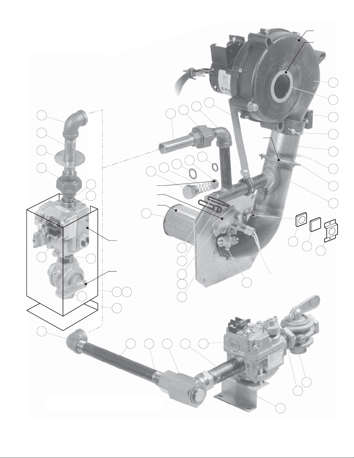
GAS CONTROL ASSEMBLY
1
16
37
17
18
19
20
21
3931 32 33 34
22
23
24
8
9
10
2
3
30
35
29
4
5
6
4
7
11
13
14
12
15
38
25
25
26
27
22
28
29
28
30
Stationary Models
Tilting
Models
34
Air Blower
Primary
Air Orifice
Secondary
Air
Orifice
Gas Orifice
Ignitor
Burner
Gas Valve
Shut-Off Valve
40 41
42
(for units built prior to March 2005)

GAS CONTROL ASSEMBLY
ITEM ON. PART NO. DESCRIPTION QTY.
1. KE53441 BLOWER, 115V, 60 HZ . . . . . . . . . . . . . . . . . . . . . . . . . . . . . . . . . . . . . . . . . . . . . . . . . . . . . . . . . . . . . . . . . . . .1
KE53441-1 BLOWER, 220V, 50 HZ . . . . . . . . . . . . . . . . . . . . . . . . . . . . . . . . . . . . . . . . . . . . . . . . . . . . . . . . . . . . . . . . . . . .1
2. KE54420 AIR INTAKE WASHER (NATURAL GAS) . . . . . . . . . . . . . . . . . . . . . . . . . . . . . . . . . . . . . . . . . . . . . . . . . . . . . . .1
KE54420-1 AIR INTAKE WASHER (PROPANE) . . . . . . . . . . . . . . . . . . . . . . . . . . . . . . . . . . . . . . . . . . . . . . . . . . . . . . . . . . .1
3. KE54239 CAPACITOR . . . . . . . . . . . . . . . . . . . . . . . . . . . . . . . . . . . . . . . . . . . . . . . . . . . . . . . . . . . . . . . . . . . . . . . . . . . . .1
4. KE01426-4 MIXING CHAMBER, 40 GALLON KETTLES . . . . . . . . . . . . . . . . . . . . . . . . . . . . . . . . . . . . . . . . . . . . . . . . . . . .1
KE01426-1 MIXING CHAMBER, 60 GALLON KETTLES . . . . . . . . . . . . . . . . . . . . . . . . . . . . . . . . . . . . . . . . . . . . . . . . . . . .1
KE01426-2 MIXING CHAMBER, 80 GALLON KETTLES . . . . . . . . . . . . . . . . . . . . . . . . . . . . . . . . . . . . . . . . . . . . . . . . . . . .1
KE01426-3 MIXING CHAMBER, 100 GALLON KETTLES . . . . . . . . . . . . . . . . . . . . . . . . . . . . . . . . . . . . . . . . . . . . . . . . . . .1
5. KE53582 TUBING 1/4 INCH SILICONE . . . . . . . . . . . . . . . . . . . . . . . . . . . . . . . . . . . . . . . . . . . . . . . . . . . . . . . . . . . . . . .1
FI05156 HOSE FITTING . . . . . . . . . . . . . . . . . . . . . . . . . . . . . . . . . . . . . . . . . . . . . . . . . . . . . . . . . . . . . . . . . . . . . . . . . . .1
6. KE53402 AIR ORIFICE, 40 GALLON KETTLES . . . . . . . . . . . . . . . . . . . . . . . . . . . . . . . . . . . . . . . . . . . . . . . . . . . . . . . . .1
KE53402-1 AIR ORIFICE, 60 - 100 GALLON KETTLES . . . . . . . . . . . . . . . . . . . . . . . . . . . . . . . . . . . . . . . . . . . . . . . . . . . . .1
KE53402-2 AIR ORIFICE, 40 GALLON KETTLES (50 HZ BLOWER) . . . . . . . . . . . . . . . . . . . . . . . . . . . . . . . . . . . . . . . . . . .1
KE53402-3 AIR ORIFICE, 60 - 100 GALLON KETTLES (50 HZ BLOWER) . . . . . . . . . . . . . . . . . . . . . . . . . . . . . . . . . . . . . .1
7. KE01449 BLOWER MOUNTING PIPE ASSEMBLY . . . . . . . . . . . . . . . . . . . . . . . . . . . . . . . . . . . . . . . . . . . . . . . . . . . . . . .1
8. KE53618 SIGHT GLASS GASKET . . . . . . . . . . . . . . . . . . . . . . . . . . . . . . . . . . . . . . . . . . . . . . . . . . . . . . . . . . . . . . . . . . . .1
9. KE53617 SIGHT GLASS . . . . . . . . . . . . . . . . . . . . . . . . . . . . . . . . . . . . . . . . . . . . . . . . . . . . . . . . . . . . . . . . . . . . . . . . . . .1
10. KE53619 SIGHT GLASS RETAINER . . . . . . . . . . . . . . . . . . . . . . . . . . . . . . . . . . . . . . . . . . . . . . . . . . . . . . . . . . . . . . . . . .1
11. KE00515 THERMISTOR . . . . . . . . . . . . . . . . . . . . . . . . . . . . . . . . . . . . . . . . . . . . . . . . . . . . . . . . . . . . . . . . . . . . . . . . . . . .1
12. KE50556-2 WATER LEVEL PROBE . . . . . . . . . . . . . . . . . . . . . . . . . . . . . . . . . . . . . . . . . . . . . . . . . . . . . . . . . . . . . . . . . . . . .1
13. KE53437-3 IGNITOR . . . . . . . . . . . . . . . . . . . . . . . . . . . . . . . . . . . . . . . . . . . . . . . . . . . . . . . . . . . . . . . . . . . . . . . . . . . . . . . .1
14. KE53570 GASKET FOR IGNITOR . . . . . . . . . . . . . . . . . . . . . . . . . . . . . . . . . . . . . . . . . . . . . . . . . . . . . . . . . . . . . . . . . . . .1
15. FI05257 SHUT-OFF COCK . . . . . . . . . . . . . . . . . . . . . . . . . . . . . . . . . . . . . . . . . . . . . . . . . . . . . . . . . . . . . . . . . . . . . . . . .1
16. FI05213 PLUG . . . . . . . . . . . . . . . . . . . . . . . . . . . . . . . . . . . . . . . . . . . . . . . . . . . . . . . . . . . . . . . . . . . . . . . . . . . . . . . . . .1
17. KE53422 SPRING . . . . . . . . . . . . . . . . . . . . . . . . . . . . . . . . . . . . . . . . . . . . . . . . . . . . . . . . . . . . . . . . . . . . . . . . . . . . . . . .1
18. FA05002-4 “O” RING . . . . . . . . . . . . . . . . . . . . . . . . . . . . . . . . . . . . . . . . . . . . . . . . . . . . . . . . . . . . . . . . . . . . . . . . . . . . . . .1
19. GAS ORIFICES:
KE53403-8 NATURAL GAS - SEA LEVEL UP TO 2000', 40 GALLON KETTLES . . . . . . . . . . . . . . . . . . . . . . . . . . . . . . . . . .1
KE53403-5 PROPANE GAS - SEA LEVEL UP TO 2000', 40 GALLON KETTLES . . . . . . . . . . . . . . . . . . . . . . . . . . . . . . . . . .1
KE53403-6 NATURAL GAS - SEA LEVEL UP TO 2000', 60 - 100 GALLON KETTLES . . . . . . . . . . . . . . . . . . . . . . . . . . . . .1
KE53403-7 PROPANE GAS - SEA LEVEL UP TO 2000', 60 - 100 GALLON KETTLES . . . . . . . . . . . . . . . . . . . . . . . . . . . . .1
KE53403-8 NATURAL GAS - 2000' UP TO 4000', 40 GALLON KETTLES . . . . . . . . . . . . . . . . . . . . . . . . . . . . . . . . . . . . . . .1
KE53403-9 PROPANE GAS - 2000' UP TO 4000', 40 GALLON KETTLES . . . . . . . . . . . . . . . . . . . . . . . . . . . . . . . . . . . . . .1
KE53403-10 NATURAL GAS - 2000' UP TO 4000', 60 - 100 GALLON KETTLES . . . . . . . . . . . . . . . . . . . . . . . . . . . . . . . . . .1
KE53403-11 PROPANE GAS - 2000' TO 4000', 60 - 100 GALLON KETTLES . . . . . . . . . . . . . . . . . . . . . . . . . . . . . . . . . . . . .1
KE53403-12 NATURAL GAS - 4000' UP TO 6000', 40 GALLON KETTLES . . . . . . . . . . . . . . . . . . . . . . . . . . . . . . . . . . . . . . .1
KE53403-13 PROPANE GAS - 4000' UP TO 6000', 40 GALLON KETTLES . . . . . . . . . . . . . . . . . . . . . . . . . . . . . . . . . . . . . .1
KE53403-10 NATURAL GAS - 4000' UP TO 6000', 60 - 100 GALLON KETTLES . . . . . . . . . . . . . . . . . . . . . . . . . . . . . . . . . .1
KE53403-14 PROPANE GAS - 4000' UP TO 6000', 60 - 100 GALLON KETTLES . . . . . . . . . . . . . . . . . . . . . . . . . . . . . . . . . .1
20. FA05002-29 “O” RING . . . . . . . . . . . . . . . . . . . . . . . . . . . . . . . . . . . . . . . . . . . . . . . . . . . . . . . . . . . . . . . . . . . . . . . . . . . . . . .1
21. FI05226-4 NIPPLE, 1/2" NPT, 5 5/16" LONG . . . . . . . . . . . . . . . . . . . . . . . . . . . . . . . . . . . . . . . . . . . . . . . . . . . . . . . . . . . . .1
22. FI00073 UNION, 1/2" . . . . . . . . . . . . . . . . . . . . . . . . . . . . . . . . . . . . . . . . . . . . . . . . . . . . . . . . . . . . . . . . . . . . . . . . . . . . .1
23. FI00133 ELBOW, 1/2", STREET . . . . . . . . . . . . . . . . . . . . . . . . . . . . . . . . . . . . . . . . . . . . . . . . . . . . . . . . . . . . . . . . . . . . .1
24. KE93909 STRIP, TO HOLD BLOWER DOWN . . . . . . . . . . . . . . . . . . . . . . . . . . . . . . . . . . . . . . . . . . . . . . . . . . . . . . . . . . .1
25. FI00040-1 ELBOW, 1/2" . . . . . . . . . . . . . . . . . . . . . . . . . . . . . . . . . . . . . . . . . . . . . . . . . . . . . . . . . . . . . . . . . . . . . . . . . . . . .1
26. FI00579 NIPPLE, 1/2" NPT, 4" LONG, KGL-60-T . . . . . . . . . . . . . . . . . . . . . . . . . . . . . . . . . . . . . . . . . . . . . . . . . . . . . . . .1
FI05226-2 NIPPLE, 1/2" NPT, 4" LONG, KGL-80-T . . . . . . . . . . . . . . . . . . . . . . . . . . . . . . . . . . . . . . . . . . . . . . . . . . . . . . . .1
27. KE55004-3 RETAINING PLATE . . . . . . . . . . . . . . . . . . . . . . . . . . . . . . . . . . . . . . . . . . . . . . . . . . . . . . . . . . . . . . . . . . . . . . . .1
28. FI00573 NIPPLE, 1/2" NPT, 1 1/8" LONG . . . . . . . . . . . . . . . . . . . . . . . . . . . . . . . . . . . . . . . . . . . . . . . . . . . . . . . . . . . . . .1
29. FI05231 BUSHING, 3/4 - 1/2" NPT FLUSH, BLACK IRON . . . . . . . . . . . . . . . . . . . . . . . . . . . . . . . . . . . . . . . . . . . . . . . .1
30. F01518-1 GAS SHUT-OFF VALVE, 3/4" (NOT FOR FRENCH CE KETTLES) . . . . . . . . . . . . . . . . . . . . . . . . . . . . . . . . . . . .1
31. FI05226 NIPPLE, 1/2" NPT, 8" LONG . . . . . . . . . . . . . . . . . . . . . . . . . . . . . . . . . . . . . . . . . . . . . . . . . . . . . . . . . . . . . . . . .1
32. FI05222 SWIVEL ELBOW . . . . . . . . . . . . . . . . . . . . . . . . . . . . . . . . . . . . . . . . . . . . . . . . . . . . . . . . . . . . . . . . . . . . . . . . . .1
33. FI05223 SPECIAL NIPPLE . . . . . . . . . . . . . . . . . . . . . . . . . . . . . . . . . . . . . . . . . . . . . . . . . . . . . . . . . . . . . . . . . . . . . . . . .1
34. KE02053 GAS VALVE ASSEMBLY . . . . . . . . . . . . . . . . . . . . . . . . . . . . . . . . . . . . . . . . . . . . . . . . . . . . . . . . . . . . . . . . . . . .1
35. KE53390 BRACKET FOR GAS VALVE . . . . . . . . . . . . . . . . . . . . . . . . . . . . . . . . . . . . . . . . . . . . . . . . . . . . . . . . . . . . . . . . .1
36. FI00607 NIPPLE, 3/4" NPT, 1 1/2" LONG . . . . . . . . . . . . . . . . . . . . . . . . . . . . . . . . . . . . . . . . . . . . . . . . . . . . . . . . . . . . . .1
37. KE01500-5 BURNER, 40 GALLON KETTLES, 140,000 BTU . . . . . . . . . . . . . . . . . . . . . . . . . . . . . . . . . . . . . . . . . . . . . . . . .1
KE01500-1 BURNER, 60-100 GALLON KETTLES, 190,000 BTU . . . . . . . . . . . . . . . . . . . . . . . . . . . . . . . . . . . . . . . . . . . . .1
38. KE53397 GASKET, BURNER . . . . . . . . . . . . . . . . . . . . . . . . . . . . . . . . . . . . . . . . . . . . . . . . . . . . . . . . . . . . . . . . . . . . . . . .1
39. FI05231 ADAPTOR . . . . . . . . . . . . . . . . . . . . . . . . . . . . . . . . . . . . . . . . . . . . . . . . . . . . . . . . . . . . . . . . . . . . . . . . . . . . . .1
40. KE601085 COVER FOR GAS VALVE . . . . . . . . . . . . . . . . . . . . . . . . . . . . . . . . . . . . . . . . . . . . . . . . . . . . . . . . . . . . . . . . . . .1
41. RB018151 GASKET FOR COVER . . . . . . . . . . . . . . . . . . . . . . . . . . . . . . . . . . . . . . . . . . . . . . . . . . . . . . . . . . . . . . . . . . . . .1
42. KE601081 BRACKET . . . . . . . . . . . . . . . . . . . . . . . . . . . . . . . . . . . . . . . . . . . . . . . . . . . . . . . . . . . . . . . . . . . . . . . . . . . . . . .1
KE01500 40 gallon before 2001
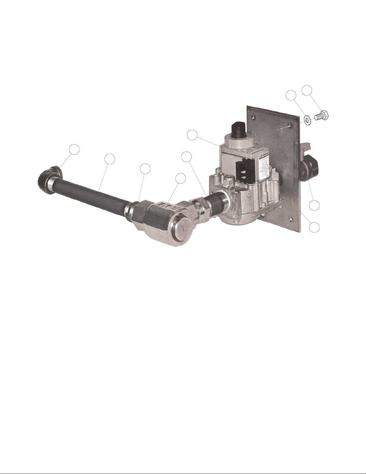
GAS CONTROL ASSEMBLY
(for units built after February 2005)
1. FI00040-1 ELBOW, 1/2" . . . . . . . . . . . . . . . . . . . . . . . . . . . . . . . . . . . . . . . . . . . . . . . . . . . . . . . . . . . . . . . . .1
2. FI05226 NIPPLE, 1/2" NPT, 8" LONG . . . . . . . . . . . . . . . . . . . . . . . . . . . . . . . . . . . . . . . . . . . . . . . . . . . . .1
3. FI05231 ADAPTOR . . . . . . . . . . . . . . . . . . . . . . . . . . . . . . . . . . . . . . . . . . . . . . . . . . . . . . . . . . . . . . . . . . .1
4. FI05222 SWIVEL ELBOW . . . . . . . . . . . . . . . . . . . . . . . . . . . . . . . . . . . . . . . . . . . . . . . . . . . . . . . . . . . . . .1
5. FI05223 SPECIAL NIPPLE . . . . . . . . . . . . . . . . . . . . . . . . . . . . . . . . . . . . . . . . . . . . . . . . . . . . . . . . . . . . .1
6. KE55240R GAS VALVE . . . . . . . . . . . . . . . . . . . . . . . . . . . . . . . . . . . . . . . . . . . . . . . . . . . . . . . . . . . . . . . . . .1
7. F015 GAS SHUT-OFF VALVE, 3/4" . . . . . . . . . . . . . . . . . . . . . . . . . . . . . . . . . . . . . . . . . . . . . . . . . . . . .1
8. KE000960 NIPPLE PLATE WELDMENT . . . . . . . . . . . . . . . . . . . . . . . . . . . . . . . . . . . . . . . . . . . . . . . . . . . . .1
9. FA30505-1 WASHER, 1/4” . . . . . . . . . . . . . . . . . . . . . . . . . . . . . . . . . . . . . . . . . . . . . . . . . . . . . . . . . . . . . . .4
10. FA11256 HEX BOLT, 1/4-20 X 1/2, 18-8 SS . . . . . . . . . . . . . . . . . . . . . . . . . . . . . . . . . . . . . . . . . . . . . . . . .4
1
2
3
4
10
9
6
5
7
Tilting
8
Models
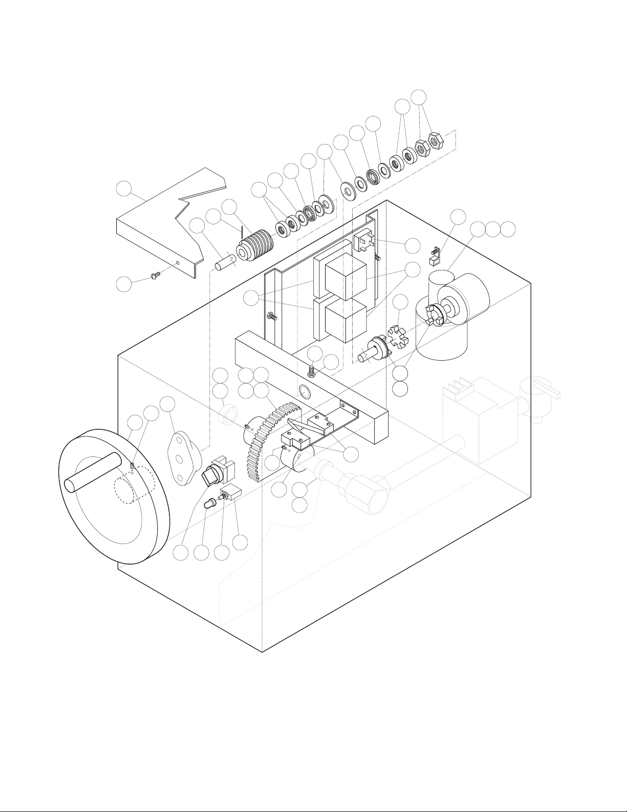
GEARBOX ASSEMBLY
40
41
42
26 27 28
39
4
5
6
5
7
5
6
5
4
8
25
15
14
1
10
2
3
9
11
12
13
16 19 20
21
22
32
30
32
31
242324
23
36
34
33
35
37
38
 Loading...