

Cleveland KEL Service Manual
CLEVELAND
INSTALLATION, OPERATION AND REPAIR MANUAL
CLEVELAND RANGE INC.
1333 East 179th St.
Cleveland. Ohio
U.S.A. 44110
(216)481-4900
9209 REV:1 213-01CC
KET-06
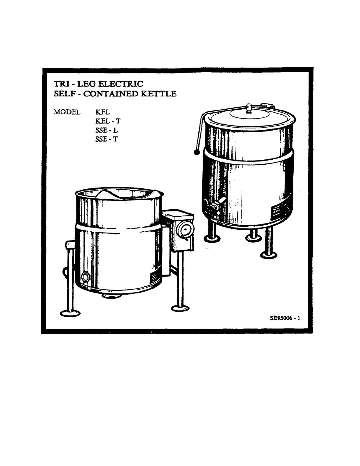
CLEVELAND
INSTALLATION, OPERATION AND MAINTENANCE
INSTRUCTIONS FOR
ELECTRIC SELF-CONTAINED KETTLES
FLOOR MODELS
KEL-25
KEL-40
KEL-60
KEL-80
KEL-100
KEL-25-T
KEL-40-T
KEL-60-T
KEL-80-T
KEL-100-T
SSE -25-L
SSE -40-L
SSE -60-L
SSE -80-L
SSE -100-L
SSE -25-T
SSE -40-T
SSE -60-T
SSE -80-T
SSE -100-T
RETAIN THIS MANUAL FOR YOUR REFERENCE
INSTALLATION INSTRUCTIONS
WARNING:
Installation of this kettle must be accompanied
by qualified electrical installation personnel
working to all applicable local and national
codes. Improper installation of this product could
cause injury or damage.
This equipment is built to comply with applicable
standards of manufacturers. Included among
these approval agencies are UL,
NSF,ASME/Ntl. Bd., CSA,ETL,and others.
Many local codes exist, and it is the
responsibility of the owner and installer to
comply with these codes.
INSPECTION
Before unpacking visually inspect the unit for
evidence of damage during shipping. If damage is
noticed, do not unpack the unit, follow shipping
damage instructions.
4. Fill out all carrier claims forms and have
the examining carrier sign and date each
form.
INSTALLATION
The first installation step is to refer to the
specification sheet for the clearance
requirements, in order to determine the location of
the kettle. Next, carefully cut open the shipping
carton for easy removal of the kettle.
SHIPPING DAMAGE INSTRUCTIONS
If shipping damage to the unit is discovered or
suspected, observe the following guidelines in
preparing a shipping damage claim.
1. Write down a description of the damage
or the reason for suspecting damage as
soon as it is discovered. This will help in
filling out the claim for ms later.
2. As soon as damage is discovered or
suspected, notify the carrier that
delivered the shipment.
3. Arrange for the carrier's representative
to examine the damage.
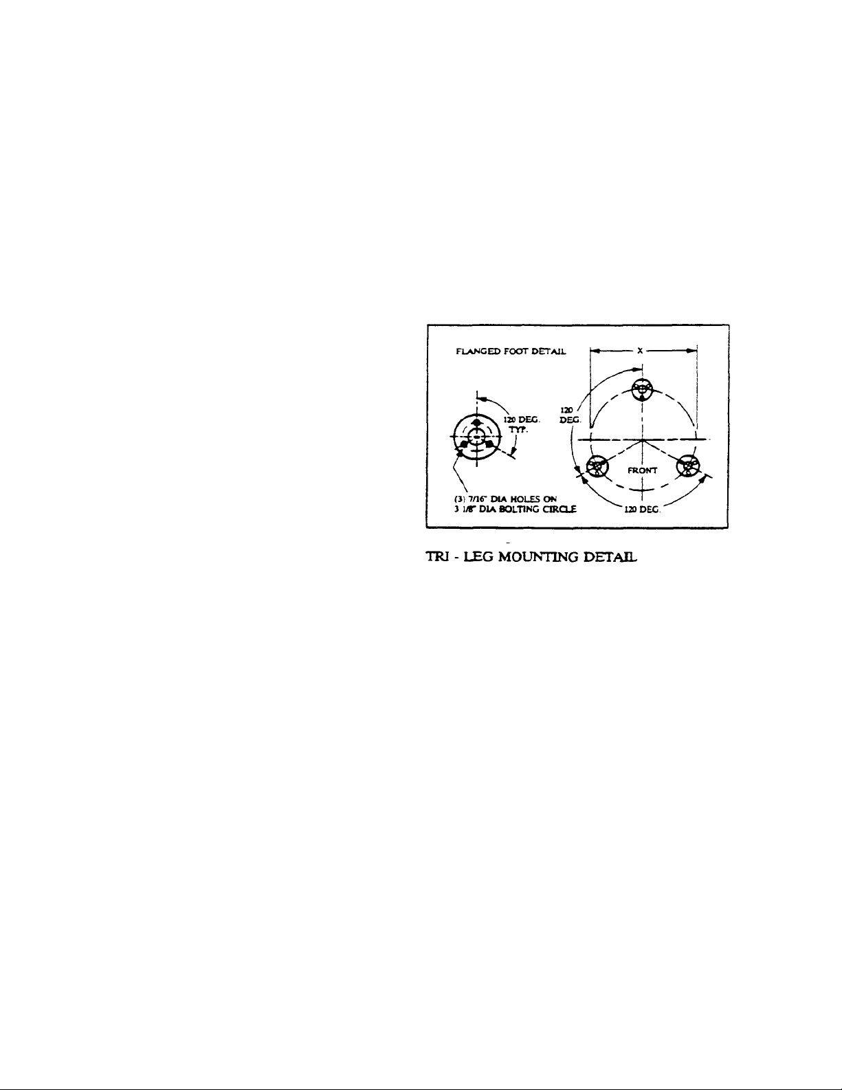
ASSEMBLY
Position the kettle in its' permanent location, and
level the kettle by turning the adjustable flanged
feet. Once positioned and leveled, permanently
secure the kettle's flanged feet to the floor using
5/16 inch lag bolts and floor anchors (supplied by
the installer). There are three bolts required to
secure each of the flanged feet.
1
ELECTRIC SERVICE CONNECTION
TILTING MODELS
Install in accordance with local codes and/or the
National Electric Code ANSI/NFPA No. 70-1990
(USA) or the Canadian Electric Code CSA
Standard C22.1 (Canada). A separate fused
disconnect switch must be supplied and installed.
The kettle must be electrically grounded by the
installer.
The electric supply must match the power
requirements specified on the kettle's rating plate.
The copper wiring must be adequate to carry the
required current at the rated voltage. Refer to
specifi cation sheet for all electrical specifications.
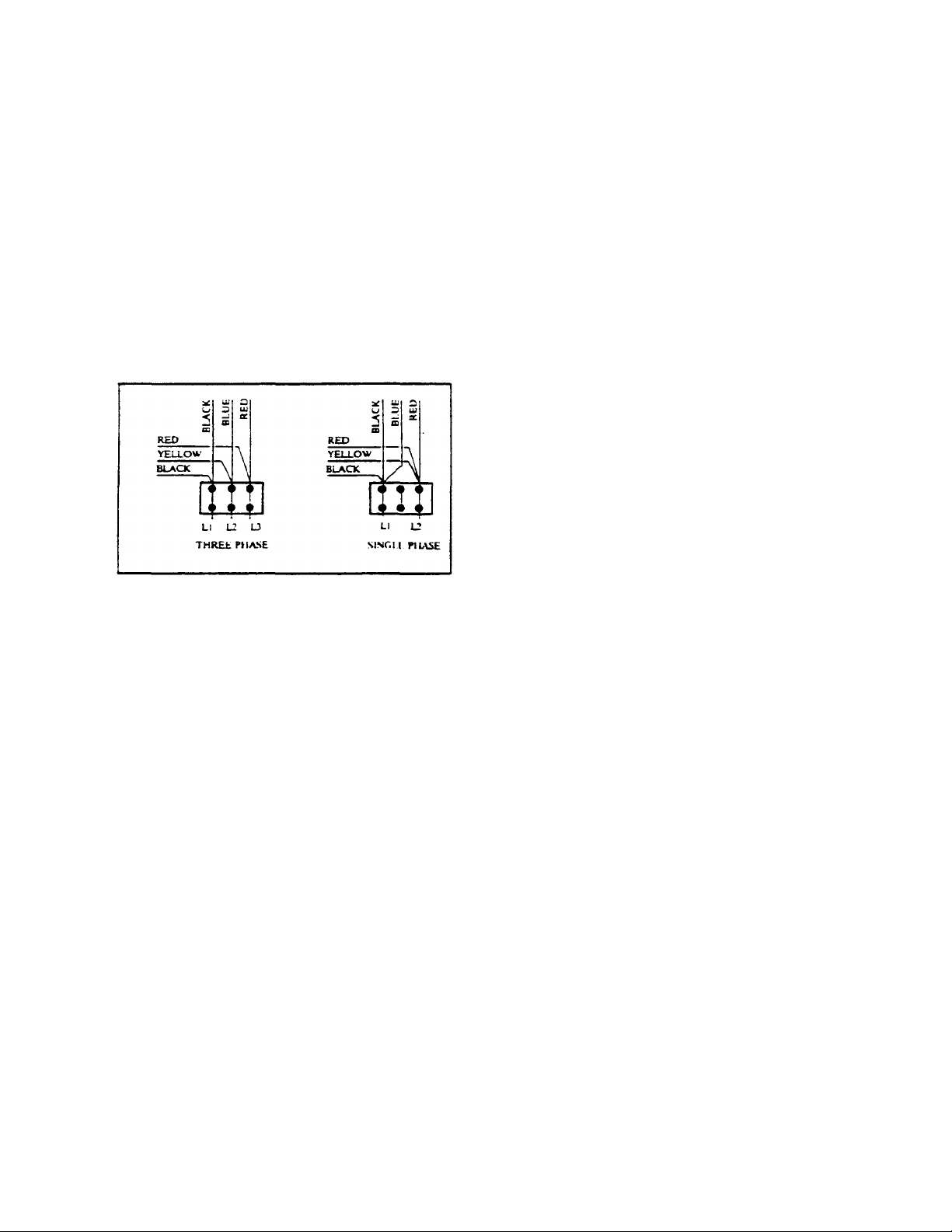
The kettle is wired for 3-phase operation at the
factory. For single phase operation, rewire the
terminal block to that shown in the accompanying
diagram.
Remove the screw at the rear of the console
cover and remove the cover. A wiring diagram is
affixed to the underside of the console cover.
Feed permanent copper wiring through the cutout in the bottom of the console, and fasten to the
three-connection terminal block. Be sure to
connect the ground wire to the separate ground
terminal connector (ground lug). Replace the
console cover and secure it with the screw.
INSTALLATION CHECK
Although the kettle has been thoroughly tested
before leaving the factory, the installer is
responsible for ensuring the proper operation of
the kettle once installed.
1. Supply power to the kettle by placing the
fused disconnect switch to the "on"
position.
2. Read the vacuum/pressure gauge to
ensure that the needle rests in the green
zone(at room temperature). If the needle
is in the "vent air" zone, refer to the
"Kettle Venting Instructions".
3. Place the kettle's power on/off switch to
the "on" position.
ELECTRICAL CONNECTION
STATIONARY MODELS
Remove the screws securing the dome -shaped
service cover underneath the kettle and remove
the cover. A wiring diagram is affixed to the
inside of cover. Fasten permanent copper wiring
to the three-connection terminal block. Be sure to
connect ground wire to the separate ground
terminal connector (ground lug). Slide the cover's
slot over the wiring and secure the cover to kettle
with the screws.
4. Turn the temperature control knob to
"min". The green LED light should
remain lit, indicating the heater elements
are energized, until the set temperature
(124°F/50°C) is reached. Then the green
light will cycle on and off with the
thermistor (solid state control).
2
5. If the kettle is a tilting model, tilt the
kettle forward. The red "low water" light
should be lit when the kettle is in a tilted
position. This light indicates that the
heater elements are not submerged in
water, and they have automatically been
shut off by the kettle's safety circuit. This
is a normal conditon when kettle is in a
tilted position.
6 Lower the kettle to the upright position.
The red "low water" light should go out
when the kettle is upright. If the red light
remains lit in the upright position, it
indicates a low water condition, and water
must be added to reservoir before the
kettle can be operated. Refer to the
"Reservoir Fill Procedures", on the kettle's
label, for details.
7. Turn the temperature control knob to
"max." and allow the kettle to preheat.
The green light should remain on until the
set temperature is reached (260°F/127°
C), then cycle on and off with the
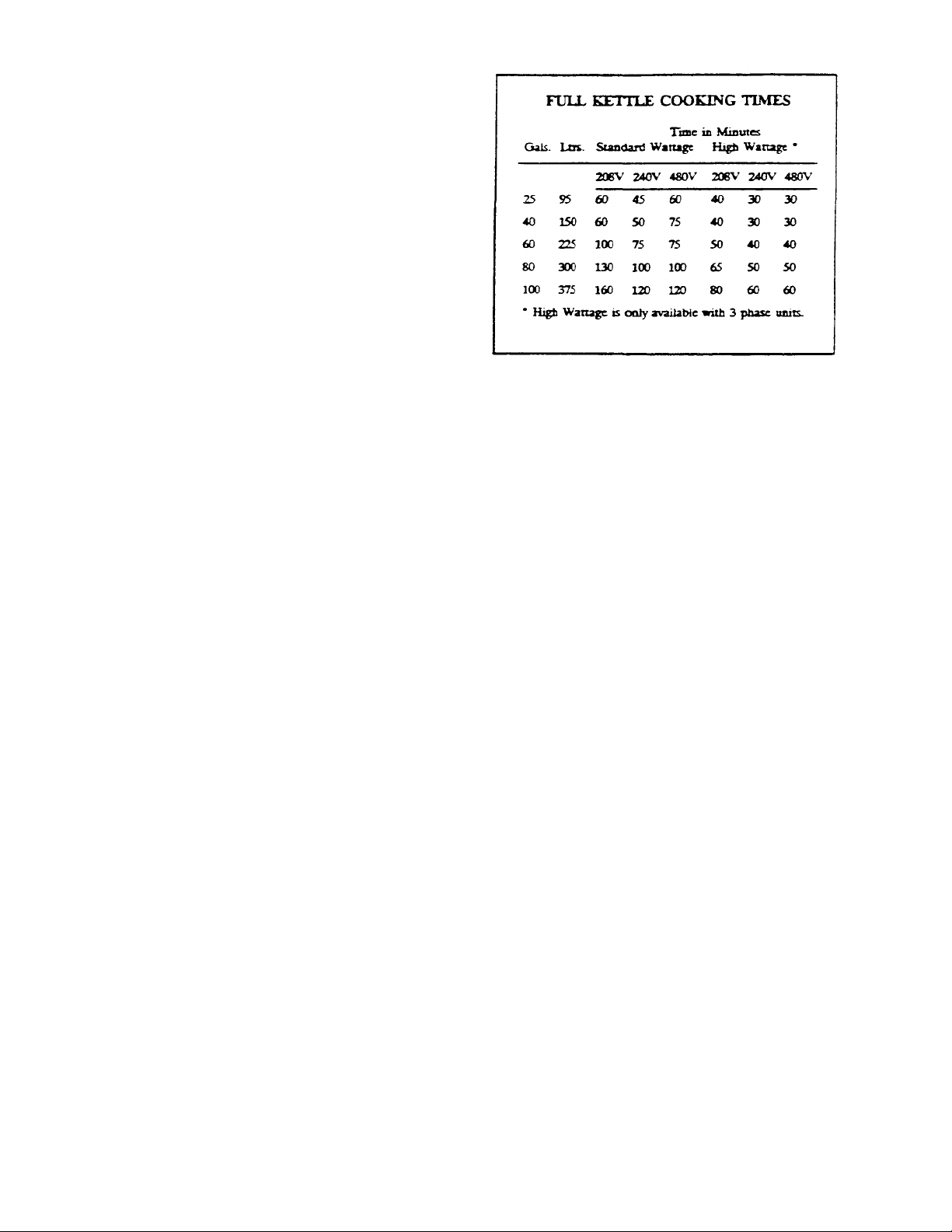
thermistor. Fill the kettle with cold water
to the steam jacket's welded seam. Refer
to the chart below for the time required to
bring the water to a boil.
8. When all testing is complete, empty the
kettle and place the power on/off switch
in the "off" position.
The accompanying chart shows
approximate times required for electric
kettles of various capacities to boil water.
Temperature control knob must be set at
"Max." throughout the heatup period.
Water will boil about 1/3 faster if the
kettle is filled only to the outer steam
jacket's welded seam, resulting in a kettle
filled to 2/3 capacity.
KETTLE VE NTING INSTRUCTIONS
If the vacuum/pressure gauge reading is in the
"vent air" zone, it means that the air has entered
the steam/water jacket, resulting in little or no
vacuum. Air inside the jacket will act as an
insulator therefore reducing kettle efficiency. To
remedy this situation, the following venting
procedures should be followed:
1. With the temperature control knob set at
number 6 or 7, heat the empty kettle
until the vacuum/pressure gauge
indicates 5-10 psi.
2. Release steam and air from the
steam/water jacket by loosening, one -half
turn, the 7/16 inch chrome-plated brass
venting valve nut (located at the rear of
the kettle) for 10-15 seconds.
3. Tighten the vent valve nut, being careful
not to overtighten.
The kettle's steam/water jacket should now be
free of air. At room temperature, the pressure
gauge needle should rest in the green zone,
indicating a vacuum in the kettle's jacket.
3

To check the gauge for proper vacuum after
venting, the temperature can be quickly reduced
by filling the kettle with cold water.
If the kettle will not hold a vacuum, have a
qualified service technician test for leaks at the
vent valve, the safety valve, the probe, and the
vacuum/pressure gauge fittings. We suggest
mixing a 50/50 solution of liquid detergent and
water while heating the kettle to at least 5 psi
pressure. Then, shut off power to the kettle at the
fused disconnect switch.
The soapy solution should be applied to the
suspected area while the gauge shows at least 5
psi pressure. Any bubbles which appear will
indicate a leak.
WARNING: The fused disconnect
switch must be off before removing the
kettle's bottom cover, which exposes
dangerous high voltage.
RESERVOIR FILL PROCEDURES
The reservoir's water level must be maintained at
the proper level to submerge the heater elements.
Under normal operating conditions, the sealed
water reservoir should never require the addition
of water. If the red "low water" light comes on
during use (while the kettle is in an upright
position), the water level has reached a critically
low level. The low water protection control has
automatically shut off the heater elements. The
following procedure must be completed before
further use:
NOTE: Have a qualified service
technician locate and repair the
leakage problem before adding
water to the unit. Ensure that the
red "low water" light is on when
the kettle is upright.
On tilting kettles, it is normal for the red light to
come on when the kettle is in a tilted position, as
the elements are not submerged in water at this
point.
1. Ensure kettle is at room temperature.
2. Shut off power to the kettle at the fused
disconnect switch.
3- Remove the bottom cover (tilting kettles
can be tilted forward for easier access to
the cover). Tilt the kettle back to the
upright position once the cover has been
removed.
4. Unscrew and remove the chrome -plated
brass venting valve nut located on the
back of the ke ttle.
5. Hold the safety valve open while adding
distilled water through the vent hole,
using a funnel. Refer to chart below for
the proper amount required.
6. Place the chrome -plated brass venting
valve nut into the water fill bole and
carefully tighten. Do not overtighten.
Replace bottom cover.
7. Restore power to the kettle at the fused
disconnect switch.
8. The kettle must now be vented. Refer to
the "Kettle Venting Instructions".
CAUTION: Only distilled water
should be used when
adding water to a
partially filled water
reservoir. Local tap water
conditions may cause
kettle damage which is
not covered under
warranty.
4

DISTILLED WATER REQUIREMENTS
When Red
When the
Reservoir is
Completely Empty,
"Low Water Light''
Kettle
Capacity
30gaL 1.80 gal 4.25 gal
40 gal
60 gal 2.10 gal 5.50 gal
80 gal 2.60 gal 6.25 gal
100 gal 2.80 gal 7.00 gal
Comes on, Add
Distilled Water
2.00 gal.
Add Distilled Water
4.50 gal
OPERATING INSTRUCTIONS
1. Before turning the kettle on, read the
vacuum/pressure gauge. The gauges needle
should be in the green zone. If the needle
is in the "vent air" zone, refer to the "Kettle
Venting Instructions". Any air that may be
present will increase cooking times. Once
heated, the kettle's normal maximum
operating pressure is approximately 10-12
psi, while cooking a water base product
2. Ensure that the electrical service to the
kettle is turned on at the fused disconnect
switch.
3. Place the kettle's power on/off switch to
the "on" position.
NOTE: When cooking egg and
milk products, the kettle
should not be preheated,
as products of this
nature adhere to hot
cooking surfaces, These
types of food should be
placed in the kettle
before heating is begun.
5. Place the food product into the kettle.
6. Turn the temperature control knob to the
required temperature setting between
"Min." (120° F/49° C) and "Max." (260°
F/127° C). The green light will cycle on
and off with the solid state control,
indicating the heaters are cycling on and
off to maintain the set temperature.
7. The red "low water" light should not be
lit during kettle operation. This light
indicates that the heater elements are not
submerged in water, and they have been
automatically shut off by the kettle's
safely circuit. On tilting kettles, it is
normal for the red light to come on when
the kettle is in a tilted position. However,
the kettle cannot be operated when the
red light remains lit while the kettle is in
the upright position. This indicates a low
water condition, and water must be added
to the reservoir. Refer to the "Reservoir
Fill Procedures " for details.
4. Preheat the kettle by turning the
temperature control knob to the desired
temperature setting (see temperature range
chart). The green light will remain lit,
indicating the heater elements are
energized, until the temperature setting is
reached. When the green light goes off, the
heaters are off, and preheating is complete.
8. When cooking is completed, place the
power on/off switch to the “off” position.
5

9. Pour the contents of the kettle into an
appropriate container by opening the
draw-off valve or tilting the kettle
forward. Care should be taken to pour
slowly enough to avoid splashing off the
product.
NOTE: As with cleaning food soil from
any cookware, an important pan of kettle
cleaning is to prevent food from drying
on. For this reason, cleaning should be
completed immediately after cooked
foods are removed. Refer to the "Care
and Cleaning Instructions" for detailed
kettle washing procedures.
WARNING: Do not use chloride base
detergents.
1. Prepare a warm water and mild detergent
solution in the kettle.
2. Remove food soil inside the kettle using
a nylon brush. Do not use a metal bristle
brush, as this may permanently damage
the kettle's stainless steel surface.
3. Loosen food which is stuck to the kettle
by allowing it to soak at a low setting.
4. If the kettle is equipped with a draw-off
valve, it should be cleaned as follows:
TEMPERATURE RANGE CHART
Temperature
Control
Setting
Minimum 120 49
1 130 54
2 145 63
3 160 71
4 170 77
5 185 85
6 195 91
7 210 99
8 230 110
9 245 118
Maximum 260 127
* Approx. Product
Temperature
°F °C
* Certain combinations of ingredients will result in
temperature variations.
a. Remove the drain screen from the
bottom of the kettle. Thoroughly
wash and rinse the screen either
in a sink or a dishwasher, then
replace it into the kettle.
b. Disassemble the draw-off valve
first by turning the valve knob
counter-clockwise, then turning
the large hex nut counterclockwise until the valv e stem is
free of the valve body.
c. In a sink, wash and rinse the
valve stem, hex nut and knob.
Wash and rinse the inside of the
valve body using a nylon brush.
d. Reassemble the draw-off valve by
reversing the procedure for
disassemble. The valve 's hex nut
should be hand tight only.
CARE AND CLEANING
Your kettle must be cleaned regularly to
maintain its fast, efficient cooking
performance, and to ensure its continued safe,
reliable operation.
6

5. Rinse kettle interior thoroughly, then
dram the rinse water.
ELECTRIC KETTLE
CALIBRATING PROCEDURE
6. Leave the cover off when the kettle is
not in use.
7. Using mild soapy water and a damp
sponge, wash the exterior of the kettle,
rinse, and dry. Avoid soaking the electric
control panel. Always turn off
equipment power before using water to
wash equipment.
NOTE: For more difficult cleaning
applications one of the following can be
used: alcohol, baking soda, vinegar, or a
solution of ammonia in water. Avoid the
use of chloride cleansers, which may
damage the kettle's stainless steel surface.
WARNING: Steel wool should never be
used for cleaning the cooking chamber of
kettle. Particles of steel wool become
embedded in the cooking surface and
rust, which may corrode the stainless
steel.
WARNING: Never hose down the kettle.
Water seeps into the underside of the
kettle, shorting and burning out the
elements.
1. Insure the unit has a vacuum before you
begin calibrating procedures. If unit
requires venting refer to "KETTLE
VENTING INSTRUCTIONS'' in this
manual.
2. Turn kettle on and set temperature dial to
maximum (10).
3. Allow the unit to cycle twice.
4. Check temperature of the inner kettle
surface with a digital thermometer.
5. Temperature should be 265°F.
6. Using a screw driver adjust temperature
by turning the potentiometer on the black
box. Turn very little. Turn clockwise to
INCREASE, and counter-clockwise to
DECREASE temperature.
7. Allow the unit to cycle twice.
8. Check temperature of the inner kettle
surface with a digital thermometer.
9. Repeat steps 4 through 8 until unit is
calibrated.
MAINTENANCE
This equipment requires very little preventive
maintenance other than daily cleaning. Some
kettles are equipped with handwheel tilting
mechanisms which require periodic preventive
maintenance to assure continued trouble-free
operation. Inspect the worm screw, tilting gears
and bearings occasionally (at least once a year).
Lubricate as required using a high temperature
grease. Remove bottom cover, heat kettle and
test pressure relief valve twice a year.
7

OPERATING CONTROLS AND INDICATORS
ITEM NO. DESCRIPTION FUNCTION
16 On-Off Toggle Switch
( Pg. 213-09DR )
20 Solid State Temperature Control Knob
( Pg. 213-09DR )
17 Heat Indicator Light (Green)
( Pg. 213-09DR )
21 Low Water Indicator Light (Red)
( Pg. 213-09DR )
15 Vacuum/Pressure Gauge
( Pg. 213-09DR )
5 Pressure Relief Valve
( Pg. 213-09DR )
Controls electrical power to kettle.
This control knob allows the operator to select
kettle heat increments from Min. to Max.(see
temperature setting chart in the operating
instructions section of this manual).
When lit, indicates that the kettle heating
elements are on. Cycles On-Off with solid state
contols.
When lit, indicates that the kettle heating
elements have cut out and the unit requires more
water. (See Reservoir Fill Procedure).
Indicates steam pressure in PSI inside the steam
jacket as well as vacuum in inches of mercury.
In the unlikely event that there is an excess steam
build-up in the jacket, this valve opens
automatically to relieve this pressure.
1 Chrome Plated Brass Vent
( Pg. 213-09DR )
NS Service Cover
( Not Shown )
1-7 Daw-Off Valve
( Pg. 600-04TD )
11 Hand Wheel
( Pg. 213-10DR )
16 Power Tilt Control Switch
( Pg. 213-12DR )
This valve is used to vent the kettle if there is
insufficient vacuum as well as for refilling the
kettle with water. (See Venting Instructions and
Reservoir Fill Procedures).
Located underneath the kettle. Remove this cover
for easy access to contactor, kettle control box,
etc.
This valve is used to empty the kettle of either
food products or wash water. It is supplied as
standard equipment on stationary models and is
optional on tilting kettles.
Turn to tilt kettle for pouring.
This switch allows the operator to tilt the kettle
up or down.
8

PARTS LIST - KETTLE BOTTOM
ITEM NO. PART NO. DESCRIPTION QTY.
1. F105025 Bleed vent elbow 1
2. KE50570 Bleed vent nut 1
3. F105022 Connector 1
4. KE50556 Probe, low water 1
5. KE51723 Safety valve, 50 PSI, 1/2" 1
6. KE50997
7. KE51226 Wire connector terminal 10
8. KF51225 Edge connector 1
9. KE00458 Solid state control box 1
10. KE50753 Relay, 12 VDC 1
11. KE51322 Contactor, 208/240V, 40 Amp. 2
KE50750 Contactor, 208/240V, 50 Amp. 2
KE50751 Contactor, 208/240V, 60 Amp. 2
12. KE50377 Terminal block section 3
SK50055 Terminal block section 3
13. KE50376 Terminal block end section 1
SK50054 Terminal block end section 1
14. KE50752 Transformer 1
15. KE50429 Pressure gauge 1
16. KE50504 Switch, toggle, SPST 1
17. KE50568
18. SK50062 Rubber boot 1
19. KE50988 Potentiometer 1
20. KE50569 Knob, potentiometer 1
21. KE50567 L.E.D. red 1
22 KE50558 Safety Thermostat (140° C) 1
23. KE00515 Thermistor 1
24. KE51005 Rotary seal 1
Blow down tube
(Standard kettles)
(Special high wattage kettles-6 elements)
(Special high wattage kettles-6 elements)
(Large, white)
(Small, black)
(Large, white)
(Small, black)
L. E. D green
1
1
9
 Loading...