

Cleveland C4ED-10.10GB Owner’s Manual
Combi Steamer
Convotherm 4
Installation Manual UL, USA - Original, ENG
Your meal. Our mission.

FOR THE INSTALLER, OPERATOR, RESPONSIBLE OWNER
FOR YOUR SAFETY
Do not store or use gasoline or other flammable vapors or liquids in the
vicinity of this or any other unit.
WARNING
Improper installation, adjustment, alteration, service or maintenance can
cause property damage, injury and death. Read the installation, operating
and maintenance instructions thoroughly before installing or servicing this
equipment.
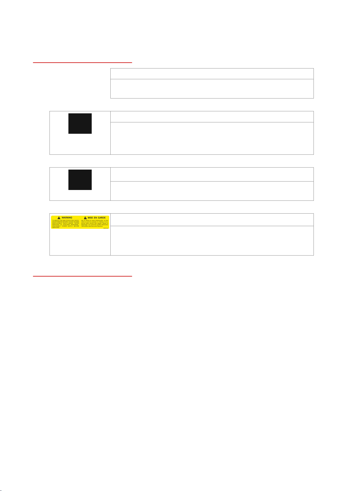
WARNING
Disconnect power at the main external power switch before servicing or
repairing a combi steamer.
WARNING
To reduce the risk of electric shock, do not remove or open cover.
No user serviceable parts inside. Refer servicing to qualified personnel.
Disconnect power supply before servicing.
IMPORTANT
IT IS COMPULSORY TO POST INSTRUCTIONS WHICH ARE TO BE FOLLOWED IN THE EVENT
THE USER SMELLS GAS. THESE INSTRUCTIONS MUST BE LOCATED IN A PROMINENT LOCA‐
TION, AND BE FULLY UNDERSTOOD BY ALL USERS OF THIS EQUIPMENT. THIS INFORMA‐
TION NEED TO BE OBTAINED FROM YOUR LOCAL GAS SUPPLIER.
ALL SERVICE MUST BE PERFORMED BY A QUALIFIED CONVOTHERM AUTHORIZED TECHNI‐
CIAN.
KEEP AREA FREE AND CLEAR OF COMBUSTIBLES.
Installation
■
Installation of this unit must be done by a licensed professional when installed in the Commonwealth
of Massachusetts.
■
The wiring diagram is located on the inner part of the side panel.
Customer documentation
■
The customer documentation is part of the combi steamer.
■
Keep the customer documentation manuals handy at all times so that you can look up any required
information.
■
Keep the customer documentation manuals for the entire life of the unit.
■
Carefully read the installation manual, the operating manual, and the operating instructions before
using, handling, and working on this unit.
■
If you transfer the combi steamer to a new owner, make sure to give the new owner the customer
documentation manuals as well.


Table of Contents
Table of Contents
1 General 8
1.1 Environmental Protection 8
1.2 Identifying Your Combi Steamer 9
1.3 Customer Documentation Structure 10
1.4 Safety Information That Must Be Read without Exception 11
1.5 About This Installation Manual 12
2 Configuration and Functions 14
2.1 The Combi Steamer's Configuration and Functions 14
2.2 Operating Panel Layout and Functions 20
3 For Your Safety 21
3.1 Basic Safety Instructions 21
3.2 Your Combi Steamer's Intended Use 23
3.3 Warning labels on combi steamer table-top models 25
3.4 Warning labels on combi steamer floor-standing models 28
3.5 Hazards and Safety Measures When Moving the Unit 31
3.6 Hazards and Safety Measures During Setup 32
3.7 Hazards and Safety Measures During Installation 33
3.8 Hazards and Safety Measures When Putting the Unit into Operation 35
3.9 Hazards and Safety Measures When Removing the Unit from Service 38
3.10 Safety Devices 41
3.11 Staff and Work Area Requirements 45
3.12 Personal Protective Equipment 47
4 Transportation 48
4.1 Safely Using the Unit 48
4.2 Transporting the unit to the installation location 49
5 Setup 50
5.1 Working Safely During Setup 50
5.2 Adjacent Systems 51
5.3 Installation location requirements 52
5.4 Unpacking 57
5.5 Removing the unit from the pallet 61
5.6 Setting Up Table-Top Models on a Work Table (Standard Equipment) 63
5.7 Setting Up Table-Top Models on an Equipment Stand (Standard Equipment) 65
5.8 Setting up the table-top model on a stand with casters 67
5.9 Setting Up Floor-Standing Models on the Floor (Standard Equipment) 70
6 Installation 71
6.1 Electrical installation 71
6.1.1 Working Safely When Installing the Electrical Installation 71
6.1.2 Planning the Electrical Installation 72
6.1.3 Performing the Electrical Installation 74
6.1.4 Connecting an Energy Optimization System (for Electrical Units Only) 75
6.1.5 Connecting the Signal Tower 77
6.1.6 Connecting the Water Treatment Filter Monitoring System 79
6.2 Gas Installation 81
6.2.1 Working Safely When Installing the Gas System 81
Installation Manual 5

Table of Contents
6.2.2 Planning the Gas Installation 83
6.2.3 Forced Air Burner and Gas Main Valve Locations 85
6.2.4 Performing the Gas Installation 87
6.2.5 Measuring the Supply Flow Pressure 88
6.2.6 Measuring the Exhaust Gas Values 89
6.3 Water connections 90
6.3.1 Working Safely When Setting Up the Water Connection and Drain Connection 90
6.3.2 Water supply 91
6.3.3 Checking the water quality 95
6.3.4 Drain Connection 96
6.4 Installing the fully automatic oven cleaning system 98
6.4.1 Working Safely During Installation 98
6.4.2 Components of Fully Automatic Oven Cleaning System 99
6.4.3 Connecting the Fully Automatic Cleaning System 101
6.5 Installing the Grease Collection Canister (ConvoGrill Only) 103
6.5.1 Working Safely During Installation 103
6.5.2 Connecting the Grease Collection Canister 104
7 Placing into operation 105
7.1 Working Safely When Putting the Unit Into Operation 105
7.2 Procedure for Placing the Unit into Operation 108
7.3 Measuring unit gaps 110
8 Removal from Service and Disposal 111
8.1 Working Safely When Removing the Unit from Service 111
8.2 Removal from Service and Disposal 113
9 Technical data 114
9.1 Dimensions and weights 115
9.2 Maximum permissible loading weight 117
9.3 Electrical supply 118
9.4 Gas Characteristic Values for Natural Gas (USA), Propane (USA) 122
9.5 Exhaust gas volume 122
9.6 Heat output 123
9.7 Water connections 123
9.8 Water quality 124
9.9 Boiler 124
9.10 Water consumption during cooking 125
9.11 Water consumption during cooking and cleaning 125
10 Connection drawings 126
10.1 Dimensions and Connection Points for Electrical Units 127
10.1.1 Convotherm 4 6.10 Electrical units 128
10.1.2 Convotherm 4 6.20 Electrical units 130
10.1.3 Convotherm 4 10.10 Electrical units 132
10.1.4 Convotherm 4 10.20 Electrical units 134
10.1.5 Convotherm 4 12.20 Electrical units 136
10.1.6 Convotherm 4 20.10 Electrical units 138
10.1.7 Convotherm 4 20.20 Electrical units 140
10.2 Dimensions and Connection Points for Gas Units 142
10.2.1 Convotherm 4 6.10 Gas Unit with Boiler 143
10.2.2 Convotherm 4 6.10 Gas Unit with Sprayer 145
10.2.3 Convotherm 4 6.20 Gas Unit with Boiler 147
10.2.4 Convotherm 4 6.20 Gas Unit with Sprayer 149
Installation Manual 6

Table of Contents
10.2.5 Convotherm 4 10.10 Gas Unit with Boiler 151
10.2.6 Convotherm 4 10.10 Gas Unit with Sprayer 153
10.2.7 Convotherm 4 10.20 Gas Unit with Boiler 155
10.2.8 Convotherm 4 10.20 Gas Unit with Sprayer 157
10.2.9 Convotherm 4 12.20 Gas Unit with Boiler 159
10.2.10 Convotherm 4 12.20 Gas Unit with Sprayer 161
10.2.11 Convotherm 4 20.10 Gas Unit with Boiler 163
10.2.12 Convotherm 4 20.10 Gas Unit with Sprayer 165
10.2.13 Convotherm 4 20.20 Gas Unit with Boiler 167
10.2.14 Convotherm 4 20.20 Gas Unit with Sprayer 169
11 Checklists and Completing the Installation 171
11.1 Checklist: Transportation, Setup, and Installation 171
11.2 Checklist: Safety guards, safety devices, and warning labels 173
11.3 Checklist: Customer briefing 174
11.4 Completing the Installation 175
Installation Manual 7

1 General
1 General
Purpose of this section
This section provides information on how to identify your combi steamer and how to use this manual.
1.1 Environmental Protection
Policy statement
Our customers' expectations, the legal regulations and standards we have to follow, and our compa‐
ny's reputation are what drives the quality and service behind all our products.
Our environmental management policy is not only designed to ensure that we are always in full com‐
pliance with all environmental laws and regulations, but also reflects our commitment to the environ‐
ment and to continuously improving our performance in this field.
In order to ensure that we meet all of our environmental goals while maintaining the high quality of our
products, and that things stay this way, we have developed a quality and environmental management
system.
This system meets the requirements set forth in ISO 9001:2008 and ISO 14001:2004.
Environmental protection measures
The following measures apply to this product:
■
Uses fully compostable packing products
■
Uses RoHS-compliant products
■
Complies with the REACH regulation
■
Recommends and uses biodegradable cleaning agents
■
E-waste recycling
■
Environmentally friendly disposal of old units through the manufacturer
Join us in our commitment to protecting the environment!
Installation Manual 8
1 General
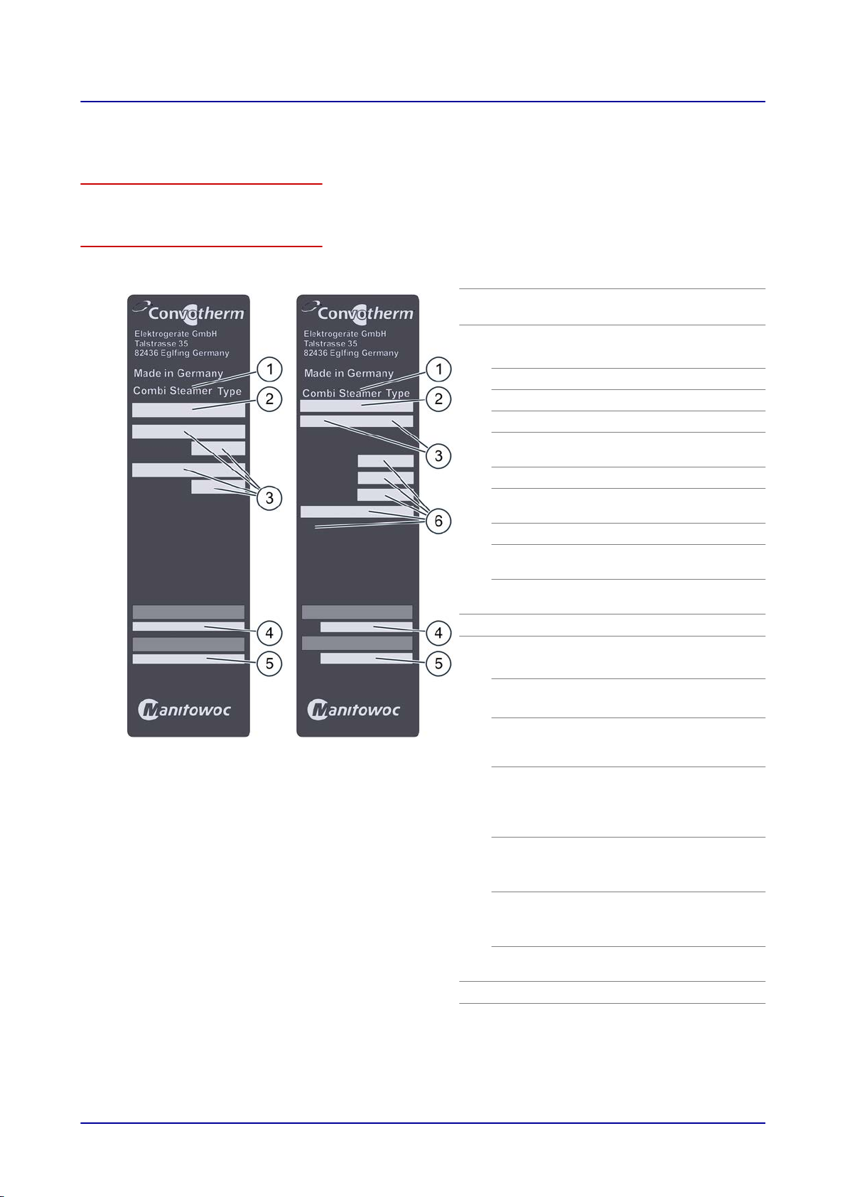
1.2 Identifying Your Combi Steamer
Nameplate location
The nameplate is found on the left side of the combi steamer.
Nameplate layout and structure
Electrical units Gas unit
Designation
Unit name
1
Combi Steamer
Trade name
2
Letters Meaning
C4 Convotherm 4 line of units
eT easyTouch controls
eD easyDial controls
xx.yy num‐
Unit size
bers
EB Electrical units with boiler
ES Electrical units with water
injection
GB Gas unit with boiler
GS Gas unit with water injec‐
tion
-N On units with NSF certifica‐
tion
Electrical specifications
3
Serial number
4
Letters Meaning
Heating
method
Steam gen‐
eration
■
Electrical units (X, V)
■
Gas unit (Y, W)
■
Sprayer (S)
■
Boiler (B)
method
Unit size
Year of
manufac‐
ture
Month of
manufac‐
ture
Consecutive
■
6.10 (1)
■
6.20 (2)
■
10.10 (3)
■
10.20 (4)
■
2014 (14)
■
2015 (15)
■
...
■
January (01)
■
February (02)
■
...
4-digit
■
■
■
number
Item number
5
Gas specifications
6
12.20 (5)
20.10 (6)
20.20 (7)
Installation Manual 9

1 General
1.3 Customer Documentation Structure
Customer documentation parts
The customer documentation for the combi steamer is made up of the following:
■
Installation manual (this manual)
■
Operating manual
■
easyTouch operating instructions (extract from the on-screen help pages)
■
On-screen help integrated into easyTouch (complete instructions for using the software)
■
easyDial Operating Instructions
Installation manual topics
The installation manual is intended for trained qualified personnel; see 'Staff Requirements' on page
45 in the installation manual.
It covers the following topics:
■
Configuration and functions: Describes the parts that are relevant when installing the combi steam‐
er
■
Safety: Goes over all the hazards involved in the various installation activities and how to prevent
and/or counter them
■
Transportation: Contains important information on transporting the combi steamer
■
Setup: Lists and describes the various setup options for the combi steamer
■
Installation: Goes over all the necessary utility and hose connections
■
Placing into operation: Explains how to put the combi steamer into operation for the first time
■
Removal from service: Goes over the activities that need to be carried out at the end of the combi
steamer's lifecycle
■
Technical data, connection diagrams: Contain all the required technical information concerning the
combi steamer
■
Checklists: Includes checklists for the combi steamer's installation and warranty
Operating manual topics
The operating manual is intended for briefed staff and trained qualified staff; see 'Staff Requirements'
in the operating manual.
It covers the following topics:
■
Configuration and functions: Describes the parts that are relevant when using the combi steamer
■
Safety: Goes over all the hazards involved in using the combi steamer and how to prevent and/or
counter them
■
Cooking: Goes over the various rules, workflows, operating steps, and actions required for cooking
■
Cleaning: Lists and describes the cleaning methods, cleaning agents, workflows, operating steps,
and actions required for cleaning
■
Maintenance: Contains warranty information; the maintenance schedule; information on faults, er‐
rors, and emergency mode; and the workflows, operating steps, and actions required for mainte‐
nance
Operating instructions and on-screen help (easyTouch only) topics
The operating instructions and the on-screen help (easyTouch only) are intended for briefed staff and
trained qualified staff; see 'Staff Requirements' in the operating manual. For units with easyTouch, the
operating instructions will be an extract from the on-screen help pages.
The operating instructions and the on-screen help (easyTouch only) cover the following topics:
■
User interface layout: Goes over the combi steamer's user interface
■
Using the software: Contains instructions on how to enter and access cooking profiles, access
cleaning profiles, and start cooking and cleaning sequences; describes the various settings and
goes over how to import and export data
■
Select cooking profiles: Lists tried-and-true cooking profiles
Installation Manual 10

1 General
1.4 Safety Information That Must Be Read without Exception
Safety information found in the documentation for the customer
Only the installation manual and operating manual provide safety information for the combi steamer.
The installation manual provides safety information for the transportation, setup, installation, placinginto-operation, and removal-from-service tasks it describes.
The operating manual provides safety information for the cooking, cleaning, and maintenance tasks it
describes.
When using the operating instructions, the operating manual or installation manual should always be
consulted in order to obtain the relevant safety information. When performing activities that go beyond
simply using the software, the safety information in the operating manual and installation manual must
always be observed.
Parts of this document that must be read without exception
Failure to take the information in this document into account may result in death, injury, or property
damage.
In order to ensure their safety and the safety of others, everyone working with/on the combi steamer
must read and understand the following parts of this document before starting any work:
■
The 'For Your Safety' on page
■
The sections describing the work that will be carried out
21 section
Danger symbol
Danger symbol Meaning
Used to warn of potential injury. Observe all the precautionary state‐
ments following this symbol in order to avoid injury or death.
Precautionary statements
The precautionary statements in this manual are categorized using the following hazard levels:
Hazard level Consequences Likelihood
Death / severe injury (irreversible) Imminent
Death / severe injury (irreversible) Potential
Minor injury (reversible) Potential
NOTICE
Property damage Potential
Installation Manual 11

1 General
1.5 About This Installation Manual
Purpose
The purpose of this installation manual is to provide everyone working with/on the combi steamer with
the information they will need to transport, set up, install, and place the unit into operation safely and
correctly.
Target groups for this installation manual
Name of target group Tasks
Person placing the unit
into operation
(service technician)
Combi steamer owner
or
the owner's employee
who is responsible for
the unit
Mover Transporting the unit within the facilities
Service technician
Electrician
Water and wastewater
installer
Gas technician Installing and uninstalling gas connections
■
Responsible overall for placing the combi steamer into operation
■
Briefing the user
■
Briefed on all of the combi steamer's safety-relevant functions, mecha‐
nisms, and devices by the person placing the unit into operation
■
Shown how the unit is operated by the person placing the unit into oper‐
ation
■
If necessary, helping out as directed with transportation within the facili‐
ties and with setting up the unit
■
Setting up the unit
■
Installing the fully automatic oven cleaning system
ConvoClean / ConvoClean+ (optional)
■
Placing the unit into operation and removing it from service
■
Connecting the unit to the electrical connection at the facilities
■
Uninstalling electrical connections
■
Connecting the unit to the water connection at the facilities
■
Uninstalling water connections
■
Connecting the unit to the drain connection at the facilities
■
Uninstalling the drain connection
Installation manual outline
Section / sub-section Purpose
General
Configuration and Func‐
tions
For Your Safety Describes all the risks and hazards posed by the unit, as well as appro‐
Transportation
Setup
■
Helps identify your unit
■
Explains how to use this installation manual
■
Describes the unit's intended use
■
Explains the unit's functions and describes where its components are
located
priate instructions on how to prevent and/or counter them
Read this section carefully!
■
Provides basic unit dimensions
■
Explains how to transport the unit to its installation location
■
Provides information on adjacent systems used for exhaust and ex‐
traction purposes
■
Provides information on the requirements concerning the installation
location
■
Explains how to unpack the unit and goes over the included equip‐
ment and parts
■
Explains how to set up the unit
Installation Manual 12

1 General
Section / sub-section Purpose
Installation Explains how to install:
Placing into operation Explains how to put the unit into operation
Removal from service and
Disposal
Technical data Contains technical specifications
Connection drawings Contains drawings with dimensions and connection points
Checklists and Completing
the Installation
Decimal mark used
■
Electrical specifications
■
Gas
■
The water and wastewater systems
■
Exhaust gas and exhaust air systems
■
The ConvoClean+ / ConvoClean fully automatic cleaning system
■
Explains how to remove the unit from service
■
Provides disposal information
■
Contains the checklists for
■
Installation
■
Safety guards, safety devices, and warning labels
■
Customer briefing
■
Provides warranty information and goes over how to use the check‐
lists at the end
In order to ensure that all numbers can be properly understood internationally, a decimal point is al‐
ways used.
Installation Manual 13
2 Configuration and Functions
2 Configuration and Functions
Purpose of this section
This section describes the combi steamer's configuration and explains its functions.
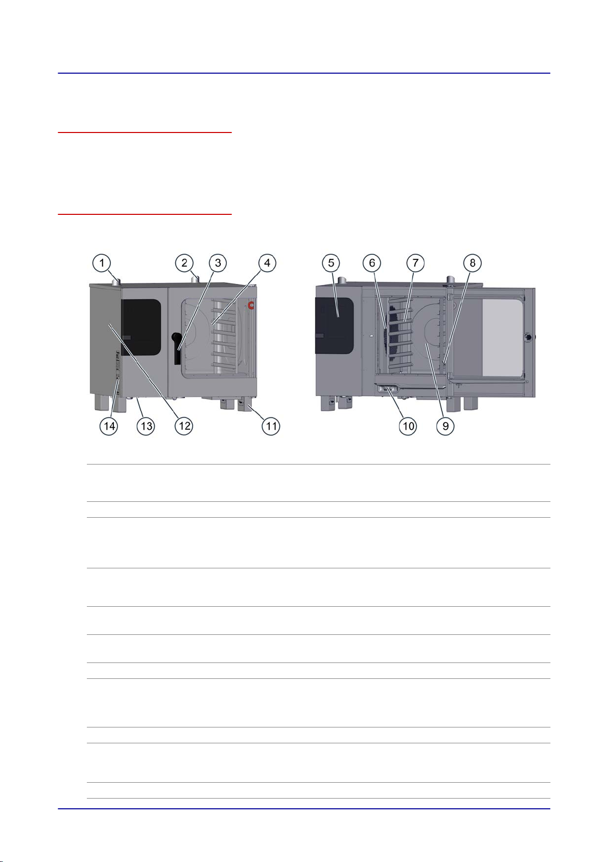
2.1 The Combi Steamer's Configuration and Functions
Parts and functions (electrical table-top models)
The figure below shows a size 6.10 combi steamer used as an example representing all electrical ta‐
ble-top models:
No. Designation Function
Ventilation port
1
■
Draws in ambient air in order to remove moisture from the oven
cavity
■
Compensates for pressure fluctuations inside the oven cavity
Air vent Lets hot steam escape
2
3
4
Door handle
Unit door
■
Used to open and close the unit door
■
Cracked-open position for safely opening the unit ('safety lock')
■
Closing-shut function
■
Antibacterial material with silver ions ("HygienicCare")
■
Seals the oven cavity
■
When opened, it can be slid backwards along the unit's side in
order to save space ('disappearing door') (optional)
Operating panel
5
Suction panel
6
Rack Used to hold standard-size bakeware
7
Core temperature probe,
8
sous vide probe (optional)
■
Used to operate the unit
■
Antibacterial ("HygienicCare")
■
Used to distribute heat uniformly within the oven cavity
■
Separates the fan compartment from the oven cavity
■
Used to measure the food's internal temperature
■
Available as an internal version that is permanently connected
inside the oven and/or as an external version that can be tem‐
porarily connected
Oven cavity Is where food is placed while it is being cooked
9
Recoil hand shower
10
(not included in certain
units)
Unit feet Are height-adjustable so as to make it possible to level the unit
11
■
Meant exclusively for rinsing the oven cavity with water
■
Is retracted automatically into its holder after being used
■
Antibacterial ("HygienicCare")
Installation Manual 14
2 Configuration and Functions
No. Designation Function
Side panel Covers the unit's wiring compartment
12
Vents at the bottom of the
13
unit
Nameplate Used to identify the unit
14
■
Used to ventilate the unit
■
Must not be blocked
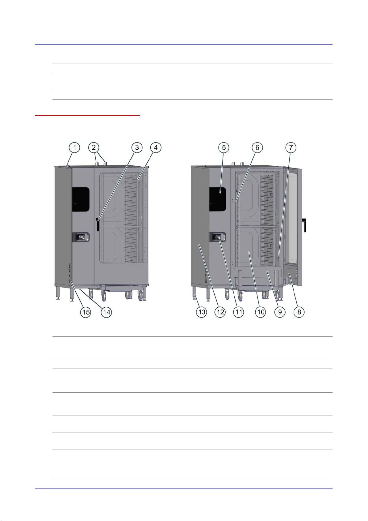
Parts and functions (electrical floor-standing models)
The figure below shows a size 20.20 combi steamer used as an example representing all electrical
floor-standing models:
No. Designation Function
Ventilation port
1
■
Draws in ambient air in order to remove moisture from the oven
cavity
■
Compensates for pressure fluctuations inside the oven cavity
Air vent Lets hot steam escape
2
3
4
Door handle
Unit door
■
Used to open and close the unit door
■
Cracked-open position for safely opening the unit
■
Antibacterial material with silver ions ("HygienicCare")
■
Seals the oven cavity
■
When opened, it can be slid backwards along the unit's side in
order to save space ('disappearing door') (optional)
Operating panel
5
Suction panel
6
Core temperature probe,
7
sous vide probe (optional)
■
Used to operate the unit
■
Antibacterial ("HygienicCare")
■
Used to distribute heat uniformly within the oven cavity
■
Separates the fan compartment from the oven cavity
■
Used to measure the food's internal temperature
■
Available as an internal version that is permanently connected
inside the oven and/or as an external version that can be tem‐
porarily connected
Installation Manual 15
2 Configuration and Functions
No. Designation Function
Integrated preheat bridge
8
in unit door
Loading trolley Used to hold standard-size bakeware
9
Oven cavity Is where food is placed while it is being cooked
10
Recoil hand shower
11
(not included in certain
units)
Side panel Covers the unit's wiring compartment
12
Unit feet Are height-adjustable so as to make it possible to level the unit
13
Vents at the bottom of the
14
unit
Nameplate Used to identify the unit
15
Works as a safety element during pre-heating and reduces ener‐
gy losses
■
Meant exclusively for rinsing the oven cavity with water
■
Is retracted automatically into its holder after being used
■
Antibacterial ("HygienicCare")
■
Used to ventilate the unit
■
Must not be blocked
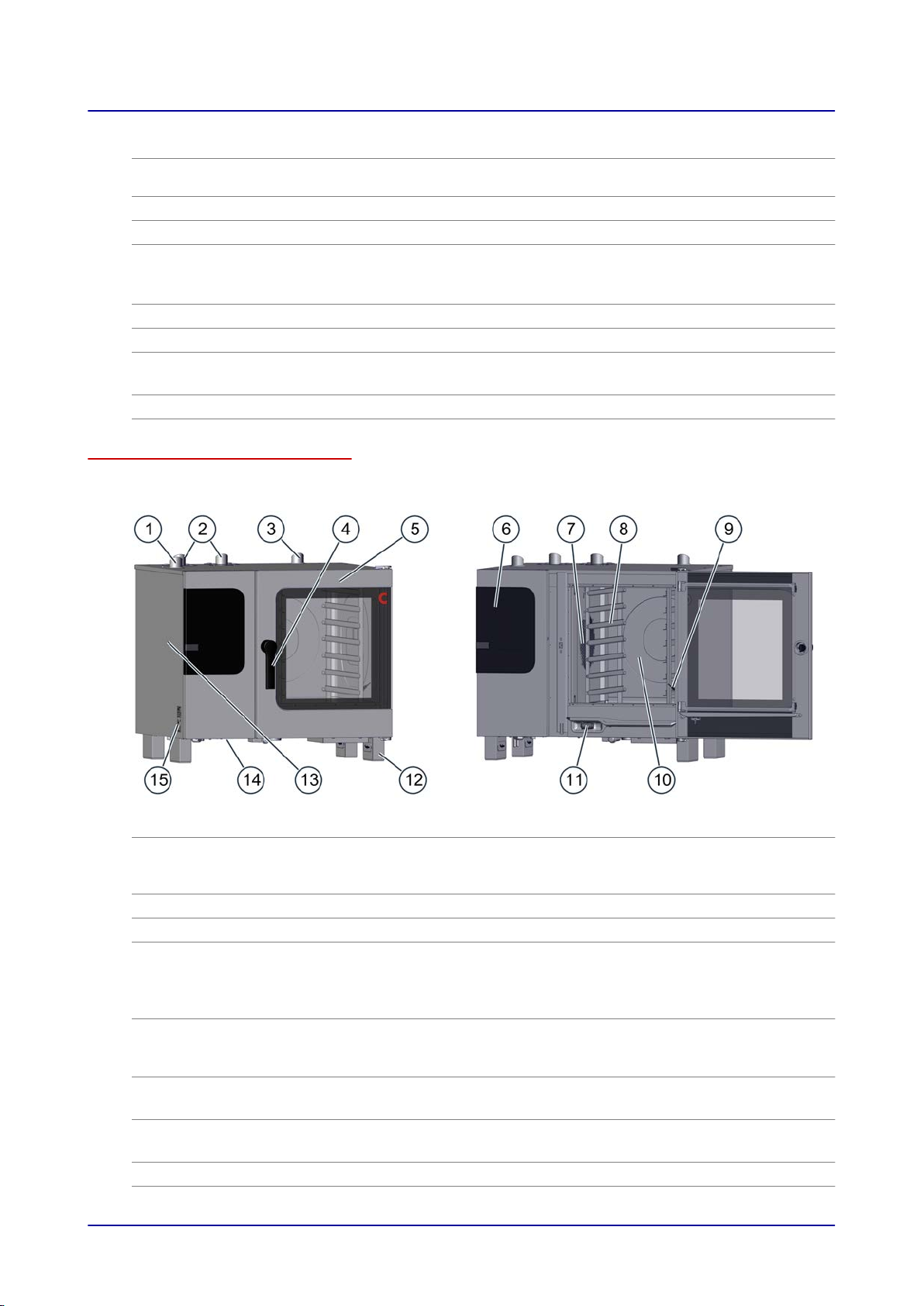
Parts and functions (gas table-top models)
The figure below shows a size 6.10 combi steamer used as an example representing all gas table-top
models:
No. Designation Function
Ventilation port
1
■
Draws in ambient air in order to remove moisture from the oven
cavity
■
Compensates for pressure fluctuations inside the oven cavity
Exhaust outlet Discharges hot exhaust gases
2
Air vent Lets hot steam escape
3
4
5
Door handle
Unit door
■
Used to open and close the unit door
■
Cracked-open position for safely opening the unit ('safety lock')
■
Closing-shut function
■
Antibacterial material with silver ions ("HygienicCare")
■
Seals the oven cavity
■
When opened, it can be slid backwards along the unit's side in
order to save space ('disappearing door') (optional)
Operating panel
6
Suction panel
7
Rack Used to hold standard-size bakeware
8
■
Used to operate the unit
■
Antibacterial ("HygienicCare")
■
Used to distribute heat uniformly within the oven cavity
■
Separates the fan compartment from the oven cavity
Installation Manual 16
2 Configuration and Functions
No. Designation Function
Core temperature probe,
9
sous vide probe (optional)
■
Used to measure the food's internal temperature
■
Available as an internal version that is permanently connected
inside the oven and/or as an external version that can be tem‐
porarily connected
Oven cavity Is where food is placed while it is being cooked
10
Recoil hand shower
11
(not included in certain
units)
Unit feet Are height-adjustable so as to make it possible to level the unit
12
Side panel Covers the unit's wiring compartment
13
Vents at the bottom of the
14
unit
Nameplate Used to identify the unit
15
■
Meant exclusively for rinsing the oven cavity with water
■
Is retracted automatically into its holder after being used
■
Antibacterial ("HygienicCare")
■
Used to ventilate the unit
■
Must not be blocked
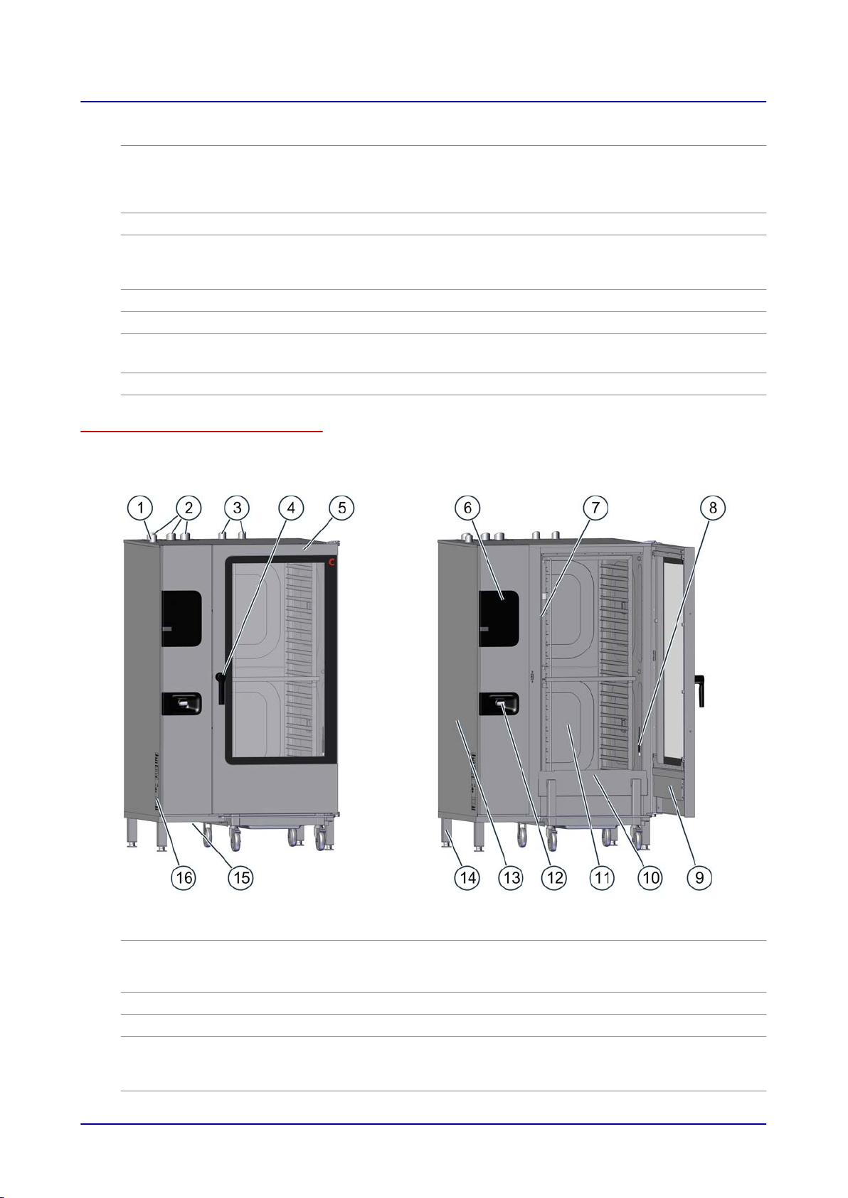
Parts and functions (gas floor-standing models)
The figure below shows a size 20.20 combi steamer used as an example representing all gas floorstanding models:
No. Designation Function
Ventilation port
1
■
Draws in ambient air in order to remove moisture from the oven
cavity
■
Compensates for pressure fluctuations inside the oven cavity
Exhaust outlet Discharges hot exhaust gases
2
Air vent Lets hot steam escape
3
4
Door handle
■
Used to open and close the unit door
■
Cracked-open position for safely opening the unit
■
Antibacterial material with silver ions ("HygienicCare")
Installation Manual 17
2 Configuration and Functions
No. Designation Function
Unit door
5
Operating panel
6
Suction panel
7
Core temperature probe,
8
sous vide probe (optional)
Integrated preheat bridge
9
in unit door
Loading trolley Used to hold standard-size bakeware
10
Oven cavity Is where food is placed while it is being cooked
11
Recoil hand shower
12
(not included in certain
units)
Side panel Covers the unit's wiring compartment
13
Unit feet Are height-adjustable so as to make it possible to level the unit
14
Vents at the bottom of the
15
unit
Nameplate Used to identify the unit
16
■
Seals the oven cavity
■
When opened, it can be slid backwards along the unit's side in
order to save space ('disappearing door') (optional)
■
Used to operate the unit
■
Antibacterial ("HygienicCare")
■
Used to distribute heat uniformly within the oven cavity
■
Separates the fan compartment from the oven cavity
■
Used to measure the food's internal temperature
■
Available as an internal version that is permanently connected
inside the oven and/or as an external version that can be tem‐
porarily connected
Works as a safety element during pre-heating and reduces ener‐
gy losses
■
Meant exclusively for rinsing the oven cavity with water
■
Is retracted automatically into its holder after being used
■
Antibacterial ("HygienicCare")
■
Used to ventilate the unit
■
Must not be blocked
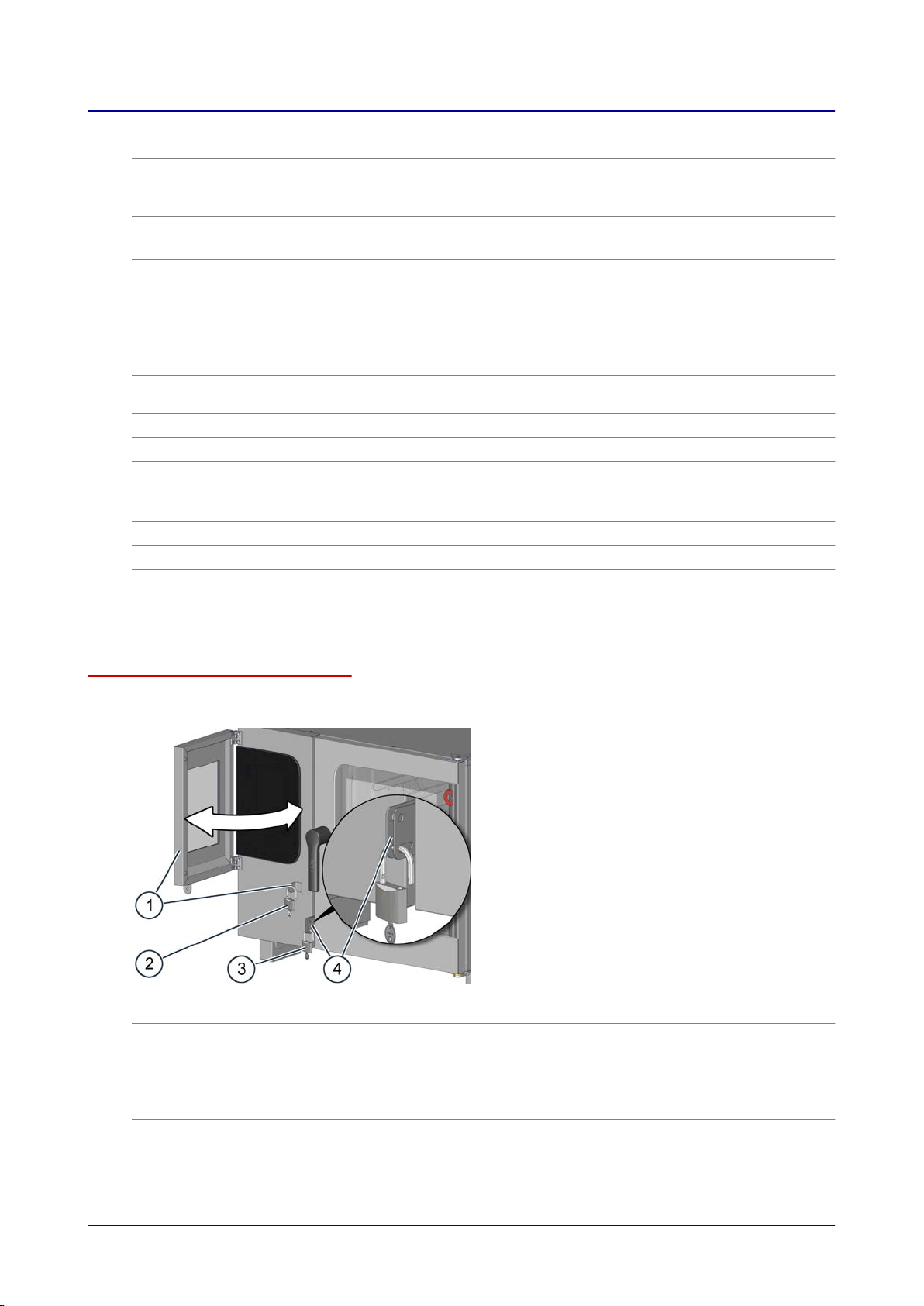
Parts and functions for special locking feature (security model only)
The figure below shows a special locking feature for enhanced security on a size 6.10 combi steamer
used as an example representing all unit sizes:
No. Designation Function
Lockable operating panel
1
cover
The cover can be swung in and secured onto the unit case so
that it covers the operating panel, preventing unauthorized users
from operating the combi steamer.
Padlock
2
■
Used to secure the operating panel cover onto the unit case
■
Not included
Installation Manual 18

2 Configuration and Functions
No. Designation Function
Padlock
3
Unit door hasp Features two different slots that can be used to lock the unit door
4
■
Used to secure the unit door onto the unit case
■
Not included
in order to prevent unauthorized users from opening and closing
it
Unit door action:
■
If the unit door is locked using the upper slot, the door will al‐
ways be fully closed.
■
If the unit door is locked using the lower slot, it will be possible
to open the door all the way to the cracked-open position.
Material
The unit's inner and outer parts are made of stainless steel.
Installation Manual 19
2 Configuration and Functions
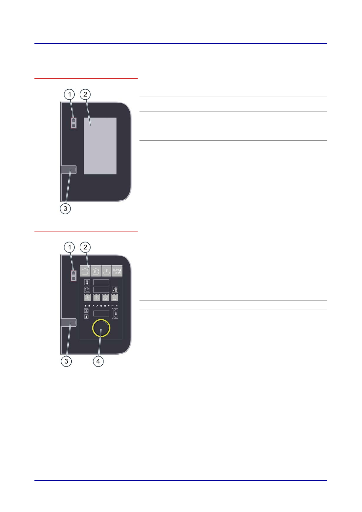
2.2 Operating Panel Layout and Functions
Operating panel layout and parts in easyTouch
No. Designation Function
1
2
3
Unit
ON/OFF switch
Full-touch dis‐
play
USB port Used to plug in a USB stick
Used to turn the combi steamer on and
off
The unit's central control interface
■
Used by touching the icons on the fulltouch display
■
Status indicators
Operating panel layout and parts in easyDial
No. Designation Function
1
2
3
4
Unit
ON/OFF switch
Used to turn the combi steamer on and
off
Control panel The unit's central control interface
■
Buttons used to enter cooking programs
■
Displays used to indicate configured
values
■
Prompt indicators for the operator
USB port Used to plug in a USB stick
C-Dial Used to set cooking parameters by turn‐
ing and pressing the encoder.
Installation Manual 20

3 For Your Safety
3 For Your Safety
Purpose of this section
The purpose of this section is to provide you with all the information you will need in order to safely
work with/on the combi steamer without putting yourself and others at risk.
Read this section very carefully!
3.1 Basic Safety Instructions
Purpose of these instructions
The purpose of these instructions is to ensure that everyone working with and on the combi steamer
will be fully aware of all the risks, hazards, and safety requirements involved and will observe the
warnings in the operating manual and on the combi steamer. Failure to follow these instructions may
result in death, injury, or property damage.
Customer documentation manuals
Follow the instructions below:
■
Fully read the 'For Your Safety' section, as well as the section that applies to the way you will be
interacting with the combi steamer.
■
Keep the customer documentation manuals handy at all times so that you can look up any required
information.
■
If you transfer the combi steamer to a new owner, make sure to give the new owner the customer
documentation manuals as well.
Basic rules for installation
The unit must be installed in compliance with all national and state laws and regulations, with all appli‐
cable local requirements and regulations set forth by the relevant local utility companies and authori‐
ties, and with all other relevant regulations and standards.
These include, but are not limited to:
■
The National Electrical Code, ANSI/NFPA 70 (current edition)
■
The Canadian Electrical Code, CSA C22.2
■
National Fuel Gas Code, ANSI Z223.1 /NFPA 54 (latest version)
■
Natural Gas and Propane Installation Code, CSA B149.1
■
The Food Code and Food Service Sanitation Manual published by the Food and Drug Administra‐
tion (FDA) (current editions)
■
Latest edition of the International Plumbing Code published by the International Code Council (ICC)
or the Uniform Plumbing Code published by the International Association of Plumbing and Mechan‐
ical Officials (IAPMO)
■
The standards published by the National Sanitation Foundation (NSF)
■
All local fire protection and occupational health and safety regulations
Working with/on the combi steamer
Follow the instructions below:
■
Only people who meet all the requirements specified in this operating manual should be allowed to
use and otherwise work with/on the combi steamer.
■
Only use the combi steamer for its intended use as described in this manual. Never, under any cir‐
cumstance, use the combi steamer for other purposes, even if they seem obvious.
■
Observe all the safety measures specified in this operating manual and on the combi steamer. This
applies especially to wearing the required personal protective equipment.
■
Make sure to always stay in the specified work areas when working with/on the combi steamer.
■
Do not make any alterations to the combi steamer. This includes removing components and add‐
ing components that have not been expressly approved.
Above all, however, make sure not to
disable any safety devices or guards.
Installation Manual 21

3 For Your Safety
For more information...
Related subjects
Your Combi Steamer's Intended Use 23
Warning labels on combi steamer table-top models 25
Warning labels on combi steamer floor-standing models 28
Hazards and Safety Measures When Moving the Unit 31
Hazards and Safety Measures During Setup 32
Hazards and Safety Measures During Installation 33
Hazards and Safety Measures When Putting the Unit into Operation 35
Hazards and Safety Measures When Removing the Unit from Service 38
Safety Devices 41
Staff and Work Area Requirements 45
Personal Protective Equipment 47
Installation Manual 22

3 For Your Safety
3.2 Your Combi Steamer's Intended Use
The combi steamer's intended use
■
The combi steamer has been designed and built exclusively for cooking a variety of food in stand‐
ard-size bakeware (steam table pans, sheet pans, etc.). Steam, convection, and combi-steam
(steam superheated without pressure) are used for this purpose.
■
The bakeware can be made of stainless steel, ceramic, plastic, aluminum, enameled steel, or
glass. Glass bakeware must not be damaged.
■
The combi steamer is intended exclusively for professional commercial use.
Limitations on use
The combi steamer should not be used to heat up the following materials:
■
Dry powders or granular products
■
Readily flammable substances or objects with a flashpoint lower than 518 °F, such as readily flam‐
mable oils, fats, and plastics
■
Food in sealed cans
Staff requirements
■
The combi steamer must be run and installed exclusively by staff meeting the specified require‐
ments. For the corresponding training and qualifications requirements, please refer to 'Staff and
Work Area Requirements on page
■
All staff must be familiar with the risks, hazards, and rules involved in handling heavy loads.
45.'
Requirements concerning the combi steamer's functional capability
■
Do not operate the combi steamer unless it has been properly transported, set up, installed, and
placed into operation as indicated in the installation manual and the person responsible for placing
it into operation has confirmed this.
■
The combi steamer should only be used if all safety devices and guards are present, working prop‐
erly, and correctly locked in place.
■
All manufacturer specifications concerning how to run and service the combi steamer must be ob‐
served.
■
The load placed inside the combi steamer must never exceed the maximum permissible loading
weight; please refer to 'Technical Data' on page
114.
Requirements concerning the combi steamer's surroundings
Required combi steamer surroundings
■
Ambient temperature between 40 °F and 95 °F
■
No toxic or potentially explosive atmospheres
■
Do not use or store gasoline or other flammable vapors, gases, or liquids in the vicinity of a combi
steamer
■
Dry kitchen floor in order to reduce the risk of accidents occurring
Required installation location characteristics
■
NO fire alarms or sprinkler system directly above the unit
■
NO flammable materials, gases, or liquids above, on, under, or close to the unit
Limitations on use
■
When used outdoors, the unit must be protected from rain and wind
■
Do NOT shift or move the unit during operation
Installation Manual 23

3 For Your Safety
Prerequisites for cleaning
■
Only use the cleaning agents approved by the manufacturer.
■
Do NOT use a pressure washer to clean the unit.
■
Do NOT use a water jet to clean the outside of the unit. Do not use the recoil hand shower for any‐
thing other than cleaning the oven cavity.
■
Do NOT use bases or acids to clean the combi steamer and make sure it is not exposed to acid
fumes. The only exception is when the oven cavity and the boiler are descaled by an authorized
service company following the manufacturer's instructions.
Installation Manual 24
3 For Your Safety
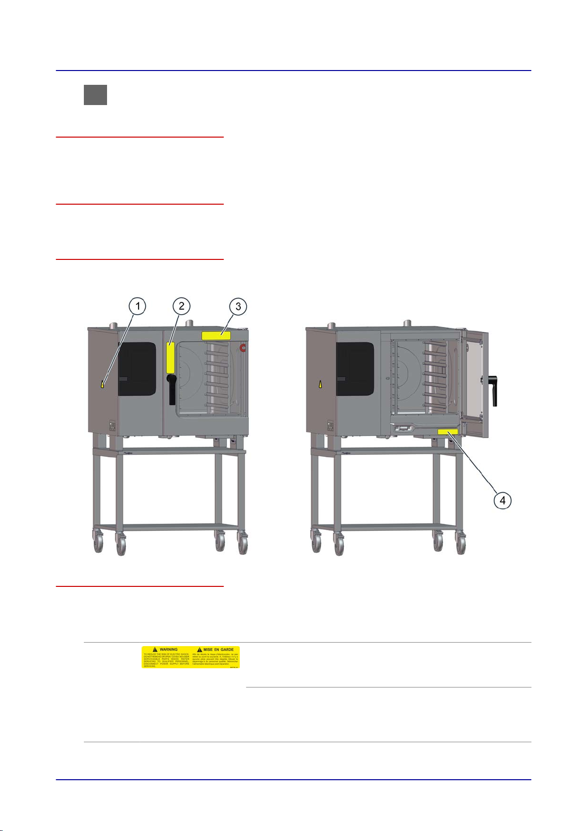
3.3 Warning labels on combi steamer table-top models
Stationary base
The term 'stationary base' refers to a stationary work table or stand for the combi steamer. These
bases are not intended to move and accordingly do not feature any components that would enable
them to do so.
Moving base
The term 'moving base' refers, for example, to a work table or stand on casters or to a stacking kit with
casters for the combi steamer.
Warning label locations on the unit
The figure below shows a size 6.10 electrical combi steamer with a moving base used as an example
representing all table-top models:
Required warning labels on the unit
The following warning labels must always be clearly visible on the combi steamer at the locations
shown in the previous figure.
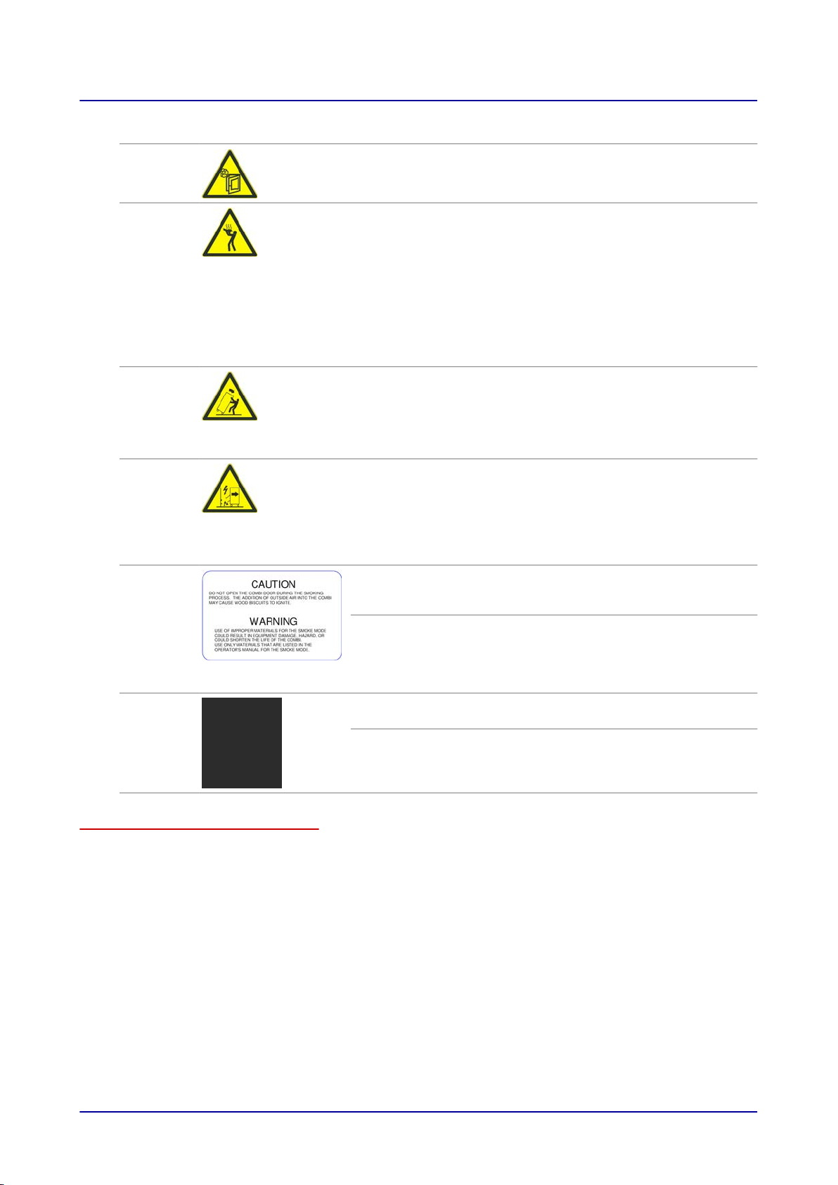
Location Warning label Description
1 and 4
Installation Manual 25
WARNING
To reduce the risk of electric shock, do not remove or open
cover. No user serviceable parts inside. Refer servicing to
qualified personnel. Disconnect power supply before servicing.
AVERTISSEMENT
Afin de réduire le risque d'électrocution, ne pas retirer ou ouvrir
le capot. Aucune pièce réparable ne se trouve à l'intérieur.
Confier le dépannage à du personnel qualifié. Débrancher l'ali‐
mentation électrique avant réparation.
3 For Your Safety
Location Warning label Description
2
Hot steam warning
There is a risk of scalding posed by the hot steam coming out
when the unit door is opened.
2
2
2
3
3
Hot food, hot bakeware, and hot liquid warning
Hot food and hot bakeware can pose a burn hazard if bakeware
topples over and out of the shelf levels or if food slides off from
bakeware being held in an inclined position. The risk of this oc‐
curring is particularly high in the case of shelf levels located
above the operator's field of view.
Risk of scalding when liquid food is spilled. This hazard exists
when liquids, or food that becomes liquefied during cooking,
are placed on the upper shelf levels. Do not use shelf levels lo‐
cated above your field of view to hold liquids or food that will
become liquefied.
Combi steamer tip-over hazard warning for when the combi
steamer is placed on a base with casters
There is a risk of the combi steamer toppling over when being
moved. Exercise extreme caution when moving the combi
steamer. When moving the combi steamer, look out for obsta‐
cles and uneven surfaces.
Unit connection damage and disconnection warning for when
the combi steamer is placed on a base with casters
There is a risk of the unit's hookups being damaged or discon‐
nected when the combi steamer is moved. Exercise extreme
caution when moving the combi steamer and take the connec‐
tions' length into account. Every time after moving it, secure the
combi steamer so that it cannot roll away by accident.
CAUTION
Do not open combi door during smoking. Outside air entering
the combi may cause wood bisquettes to ignite.
WARNING
The use of improper materials for smoke mode may result in
equipment damage or hazards or may shorten the life of the
combi. Only use materials listed for smoke mode in the opera‐
tor's manual.
CAUTION
Door(s) and handle(s) may be hot.
ATTENTION
Porte(s) et poignée(s) chaudes
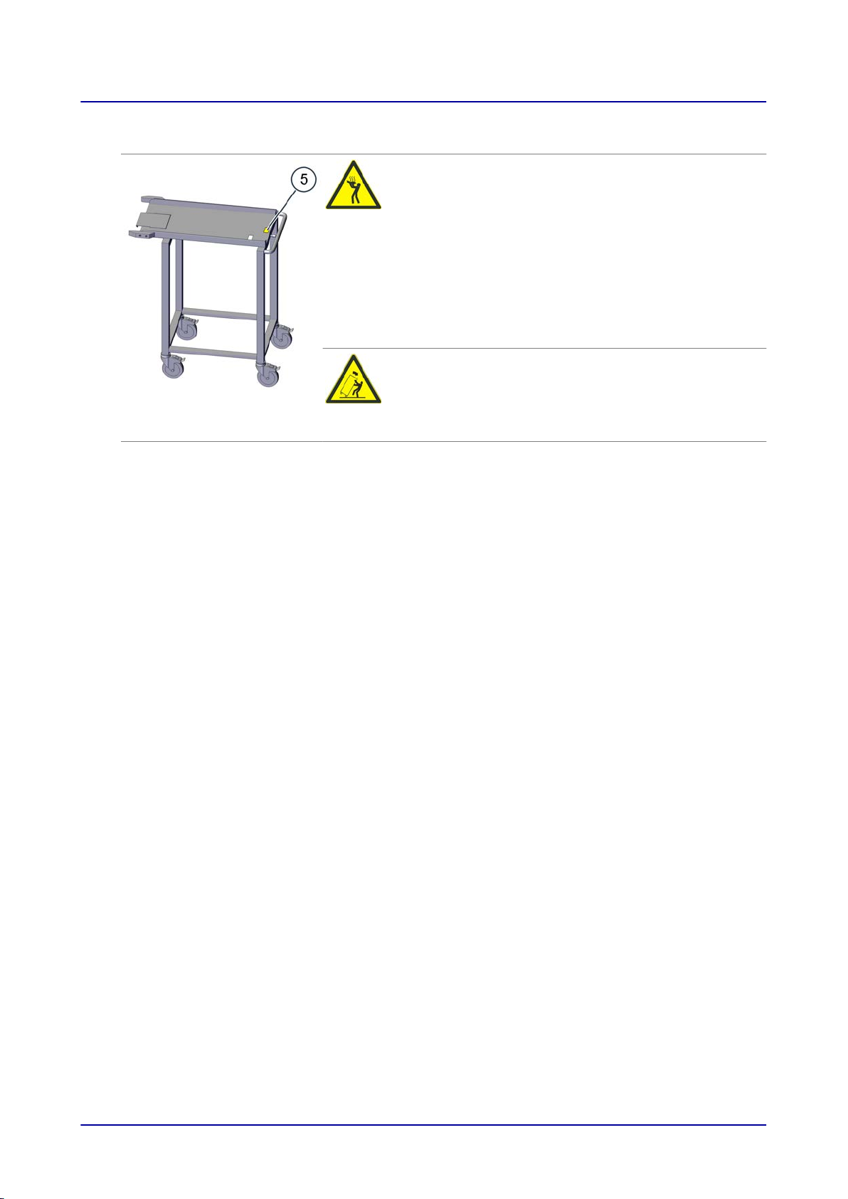
Required warning labels on the optional transport trolley (does not apply to ConvoSmoke)
The following warning labels must always be clearly visible on the transport trolley at the location
shown in the figure below.
Installation Manual 26
3 For Your Safety
Location 5 Warning label Description
Hot food, hot bakeware, and hot liquid warning
Hot food and hot bakeware can pose a burn hazard
if bakeware topples over and out of the shelf levels
or if food slides off from bakeware being held in an
inclined position. The risk of this occurring is partic‐
ularly high in the case of shelf levels located above
the operator's field of view.
Risk of scalding when liquid food is spilled. This
hazard exists when liquids, or food that becomes
liquefied during cooking, are placed on the upper
shelf levels. Do not use shelf levels located above
your field of view to hold liquids or food that will be‐
come liquefied.
Transport trolley tip-over hazard warning
There is a risk of the transport trolley toppling over
when being moved. Exercise extreme caution when
moving the transport trolley. When moving the
transport trolley, look out for obstacles and uneven
surfaces.
Installation Manual 27
3 For Your Safety
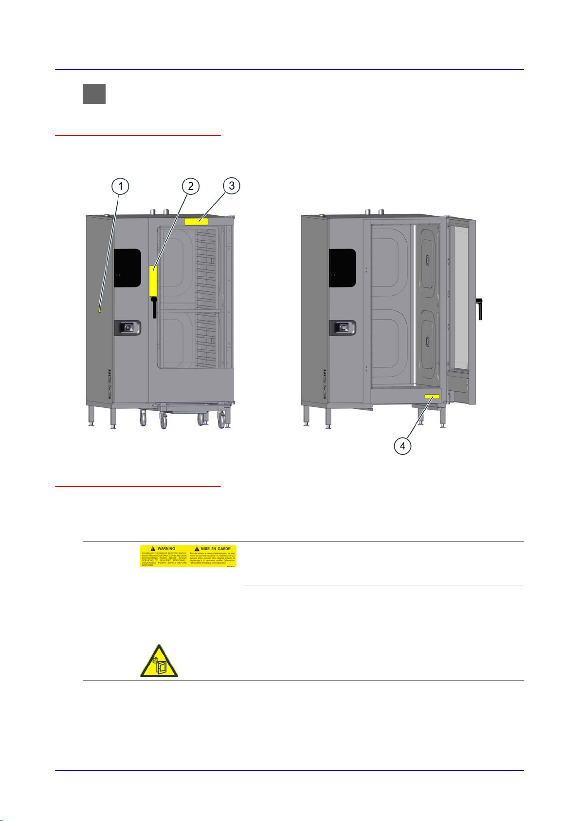
3.4 Warning labels on combi steamer floor-standing models
Warning label locations on the unit
The figure below shows a size 20.20 electrical combi steamer used as an example representing all
floor-standing models:
Required warning labels on the unit
The following warning labels must always be clearly visible on the combi steamer at the locations
shown in the previous figure.
Location Warning label Description
1 and 4
2
WARNING
To reduce the risk of electric shock, do not remove or open
cover. No user serviceable parts inside. Refer servicing to
qualified personnel. Disconnect power supply before servicing.
AVERTISSEMENT
Afin de réduire le risque d'électrocution, ne pas retirer ou ouvrir
le capot. Aucune pièce réparable ne se trouve à l'intérieur.
Confier le dépannage à du personnel qualifié. Débrancher l'ali‐
mentation électrique avant réparation.
Hot steam warning
There is a risk of scalding posed by the hot steam coming out
when the unit door is opened.
Installation Manual 28
3 For Your Safety
2
3
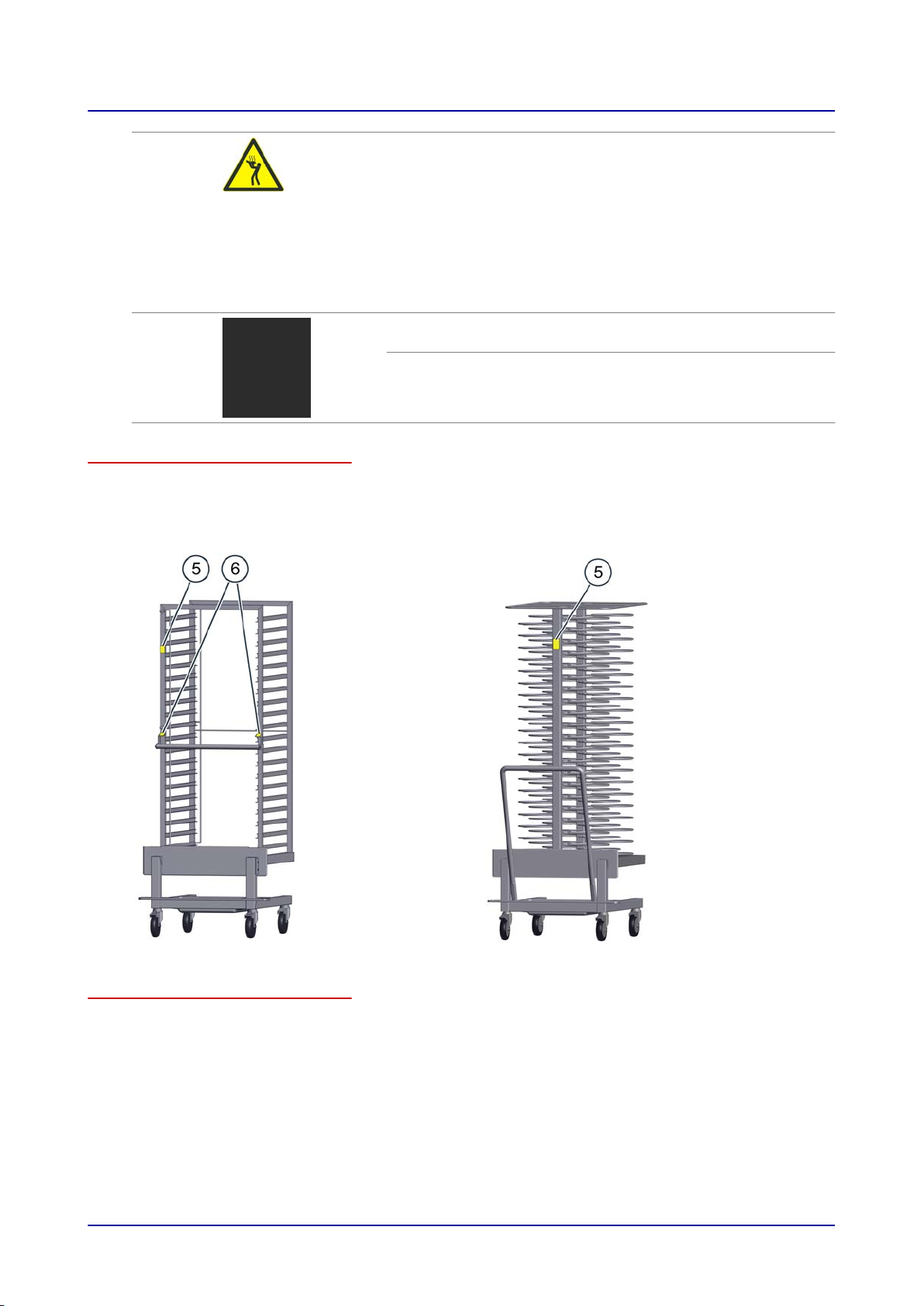
Warning label locations on the loading trolley
The figure below shows a loading trolley and a plate loading trolley for a size 20.20 combi steamer
used as examples representing all unit sizes:
Loading trolley Plate loading trolley (optional)
Hot food, hot bakeware, and hot liquid warning
Hot food and hot bakeware can pose a burn hazard if bakeware
topples over and out of the shelf levels or if food slides off from
bakeware being held in an inclined position. The risk of this oc‐
curring is particularly high in the case of shelf levels located
above the operator's field of view.
Risk of scalding when liquid food is spilled. This hazard exists
when liquids, or food that becomes liquefied during cooking,
are placed on the upper shelf levels. Do not use shelf levels lo‐
cated above your field of view to hold liquids or food that will
become liquefied.
CAUTION
Door(s) and handle(s) may be hot.
ATTENTION
Porte(s) et poignée(s) chaudes
Required warning labels on the loading trolley
The following warning labels must always be clearly visible on the loading trolley and (if applicable) on
the plate loading trolley at the locations shown in the previous figures.
Installation Manual 29
3 For Your Safety
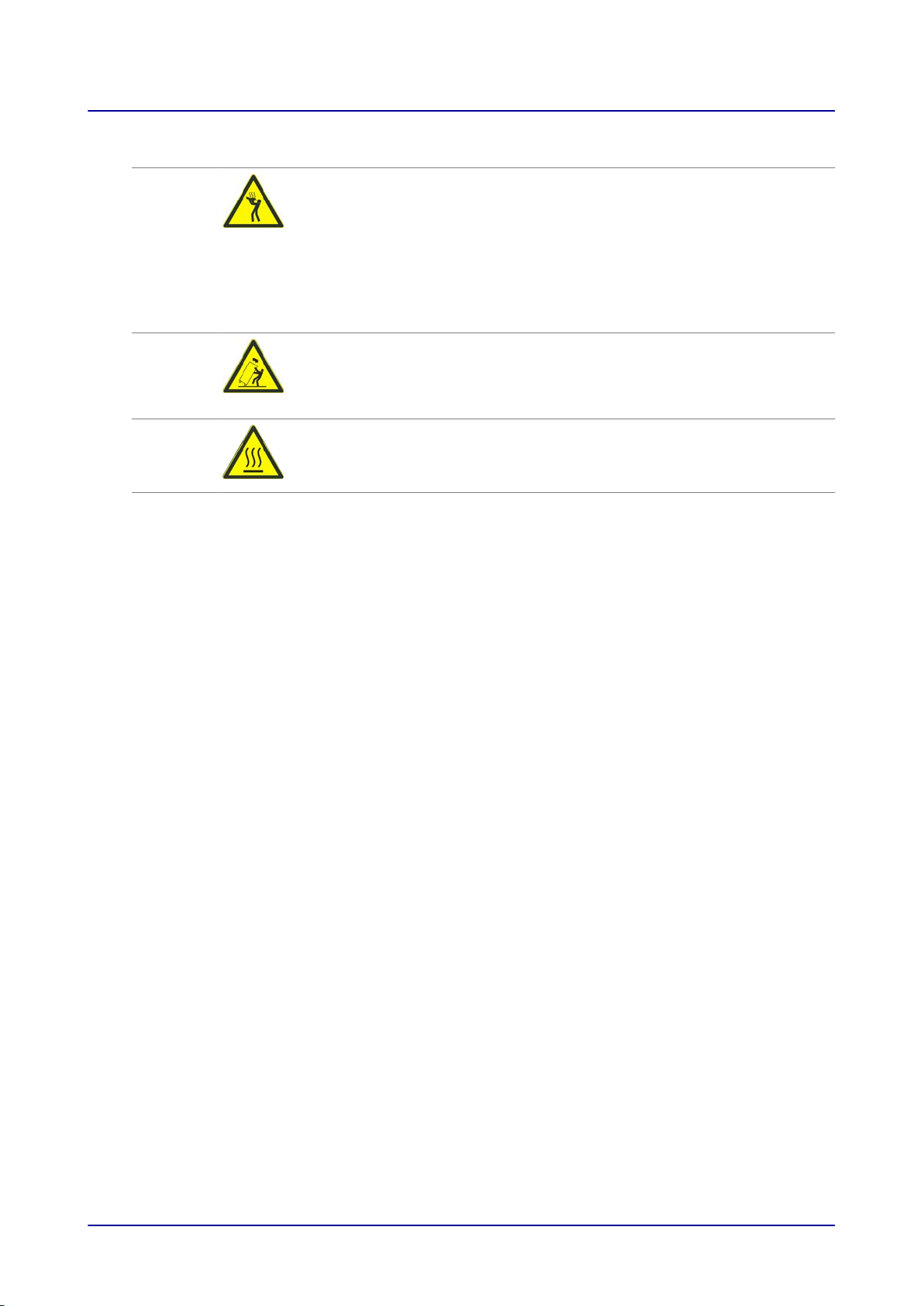
Location Warning label Description
5
5
6
Security
models on‐
ly
Hot food, hot bakeware, and hot liquid warning
Hot food and hot bakeware can pose a burn hazard if bakeware top‐
ples over and out of the shelf levels or if food slides off from bakeware
being held in an inclined position. The risk of this occurring is particu‐
larly high in the case of shelf levels located above the operator's field
of view.
Risk of scalding when liquid food is spilled. This hazard exists when
liquids, or food that becomes liquefied during cooking, are placed on
the upper shelf levels. Do not use shelf levels located above your field
of view to hold liquids or food that will become liquefied.
Loading trolley and plate loading trolley tip-over hazard warning
There is a risk of the loading trolley or plate loading trolley toppling
over when being moved. Exercise extreme caution when moving the
loading trolley or plate loading trolley. When moving the loading trolley
or plate loading trolley, look out for obstacles and uneven surfaces.
Hot surface warning
Hot surfaces on the loading trolley's handle pose a burn hazard.
Installation Manual 30
 Loading...