

Page 1

Statement of Responsibilities
This document is for use by experienced and trained Qualified Cleveland Range, LLC Authorized Service
Representatives who are familiar with both the safety procedures, and equipment they service.
Cleveland Range, LLC assumes no liability for any death, injury, equipment damage, or property damage
resulting from use of, improper use of, or failure to use the information contained in this document.
Cleveland Range, LLC has made every effort to provide accurate information in this document, but
cannot guarantee that this document does not contain unintentional errors and omissions.
The information in this document may be subject to technical and technological changes, revisions, or
updates.
Cleveland Range, LLC assumes no liability or responsibility regarding errata, changes, revisions, or
updates.
Qualified Cleveland Range, LLC Authorized Service Representatives are obligated to follow industry
standard safety procedures, including, but not limited to, OSHA regulations, and disconnect / lock out /
tag out procedures for all utilities including steam, and disconnect / lock out / tag out procedures for gas,
electric, and steam powered equipment and / or appliances
All utilities (gas, electric, water and steam) should be turned OFF to the equipment and locked out of
operation according to OSHA approved practices during any servicing of Cleveland Ran ge equipment
Qualified Cleveland Range, LLC Authorized Service Representatives are obligated to maintain up-to-date
knowledge, skills, materials and equipment.
Page 2

CLEVELAND RANGE
SEQUENCE OF OPERATIONS
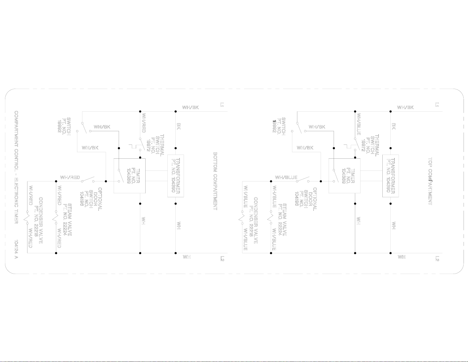
Convection Top
Electronic Timer
1. To turn the unit on, depress the red on/off rocker switch at the base.
• 115 VAC is sent to the red indicator light in the switch
• 115 VAC is sent to the 24 VAC timer transformer.
• 24 VAC is sent to the timer.
• 115 VAC is sent to the timed/manual switch.
2. With the timed/manual switch in the timed position (with time on the timer) or in the manual
position.
• The timer display alternates between “PAUS” and the set time.
• 115 VAC is sent through the optional door switch.
• 115 VAC is sent to the condensate solenoid and cold water is sent to the condensate
spray nozzle.
• 115 VAC is sent to the steam solenoid and steam is sent to the cooking cabinet. There
the steam is directed around the product and pulled down the drain by the condensate
spray.
• When the cooking compartment reaches 193 degrees internally the thermal switch closes
and the timer begins to count down.
3. When the timer counts down in the timed position:
• 115 VAC is removed from the condensate circuit.
• 115 VAC is removed from the steam solenoid.
4. The unit is turned off by depressing the red rocker switch.
Page 3
Page 4

CLEVELAND RANGE
SEQUENCE OF OPERATIONS
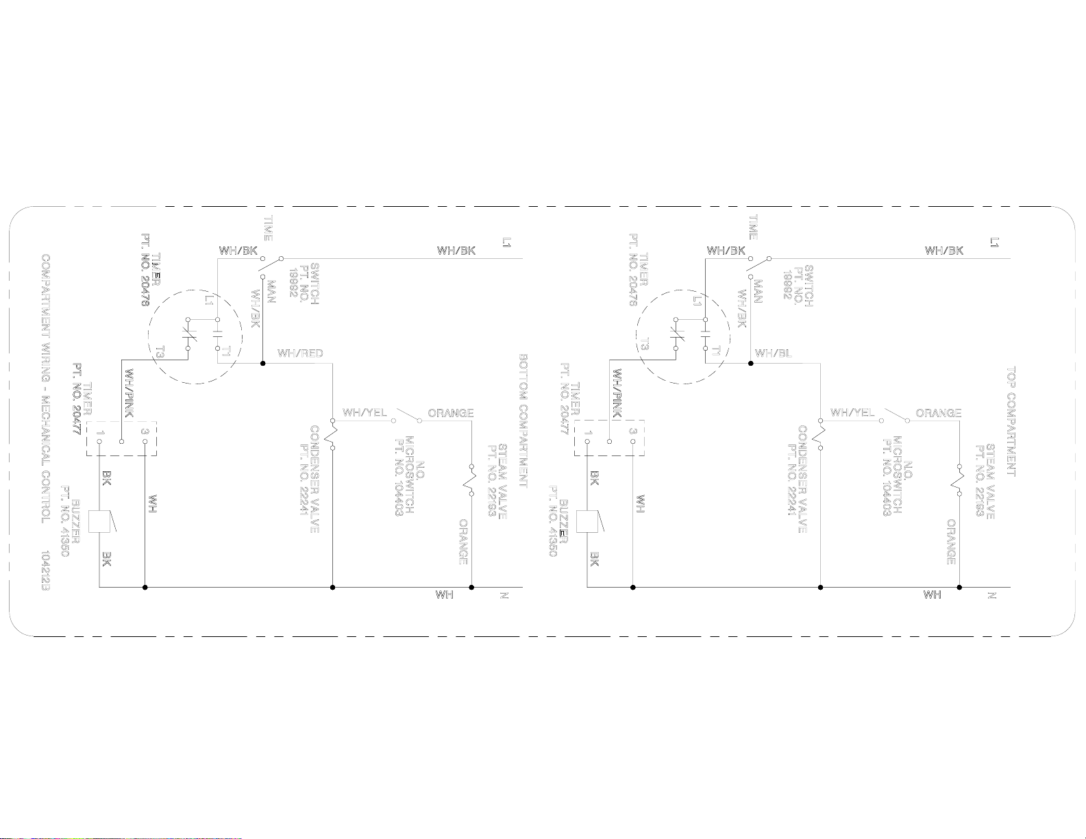
Convection Top
Mechanical Timer
1. To turn the unit on, depress the red on/off rocker switch at the base.
• 115 VAC is sent to the red indicator light in the switch
• 115 VAC is sent to the timed/manual switch.
2. With the timed/manual switch in the timed position (with time on the timer) or in the manual
position.
• 115 VAC is sent through the optional door switch.
• 115 VAC is sent to the condensate solenoid and cold water is sent to the condensate
spray nozzle.
• 115 VAC is sent to the steam solenoid and steam is sent to the cooking cabinet. There
the steam is directed around the product and pulled down the drain by the condensate
spray.
3. When the timer counts down in the timed position:
• 115 VAC is removed from the condensate circuit.
• 115 VAC is removed from the steam solenoid.
• 115 VAC is sent to the 3-second timer
• 115 VAC is sent from the 3-second timer to the buzzer for 3 seconds.
4. The unit is turned off by depressing the red rocker switch.
Page 5
Page 6
Cleveland Range, LLC
1333 East 179th St., Cleveland, Ohio, U.S.A. 44110
Ph: 1-216-481-4900 Fx: 1-216-481-3782 Visit our Web Site at www.clevelandrange.com
Page 7

CLEVELAND RANGE
SEQUENCE OF OPERATIONS
Gas Boiler Base
1. To turn the unit on, depress the red on/off rocker switch.
x 115 VAC is sent to the terminal block in control box.
x 115 VAC is sent to normally open blowdown valve closing it.
x 115 VAC is sent to L1 and L2 of the water level board.
2. With the water level board energized and no water in the boiler
x 115 VAC is sent from the IND terminal to the low water indicator light.
x 115 VAC is sent from the WF terminal to the fill solenoid.
x The fill solenoid opens and the boiler fills.
x The water fills to the low probe shorting it to ground
x 115 VAC is removed from the IND terminal and the low water indicator light is
de-energized.
x 115 VAC is sent from the HTR terminal through the normally closed contact of
the high-pressure switch to the amber reset switch,
x 115 VAC is sent through the normally closed R1B contact to energize the amber
light.
x If the low probe is not grounded for 20 seconds, 115 VAC is removed from
HTR and sent back to IND energizing the low water indicator light.
3. When the momentary amber switch is depressed 115 VAC is sent to the R1 relay closing it.
x The normally closed R1B contacts open de-energizing the amber light.
x The relay latches itself through contacts 3 and 5 with a jumper to the coil.
x If either the high-pressure switch opens or the low probe circuit on the water level
board opens, then the latch circuit opens.
x When the water level or pressure returns to a safe condition the amber light will
energize and the process may begin again.
x The R1B relay contacts close sending 115 VAC through the normally closed operating
pressure switch to the 24 VAC transformer.
x 24 VAC is sent to the ignition module.
4. With 24 VAC to the ignition module 24 VAC is sent to the gas valve.
x The gas valve is energized.
x The gas valve opens to the initial stage and sends gas to the burner.
x The initial stage for a 200,000 BTU boiler base natural gas is 1.25” W.C.
x The initial stage for a 300,000 BTU Boiler base natural gas is .75” W.C.
x The inital stage for L.P. boiler base is 2.5” W.C.
x A spark is generated at the igniter.
x The gas is ignited and the flame rectifies the AC current.
x The ignition module reads 1.5 micro amps DC current through the ground wire.
Page 8

x If the module does not read 1.5 micro amps DC in 4 seconds it will lock out.
x When the ignition module locks out 24 VAC is sent to the buzzer from the alarm
terminal on the module.
x The gas valve continues to open to 3.5” water column in 6-8 seconds for natural gas
boiler base and 10” W.C. for L.P.
5. The water in the boiler is heated to steam.
x As steam is generated and pressure builds the air is pushed out through the steamtrap.
x When steam goes through the steam trap and heats it to 192 degrees it closes.
6. Pressure builds in the boiler to the set point (8 PSI).
x The operating pressure switch opens and the heat circuit is de-energized.
x When the pressure drops below the set point the heat circuit is energized and the heat
process begins again.
7. Water continues to fill until the high probe is grounded.
x When the high probe is grounded the WF terminal on the water level board is de-
energized.
x The fill solenoid closes until the high probe is ungrounded for 5 seconds.
x If the water level drops below the high probe for more than 5 seconds the WF terminal
is energized and the water fill circuit begins again.
8. When the unit is turned off, by depressing the red rocker switch,
x 115 VAC is removed from the heat circuit.
x 115 VAC is removed from the drain circuit and the normally open drain valve opens
allowing the unit to drain.
x 115 VAC is sent to the 3-minute timer.
x The three-minute timer will energize the fill solenoid for 3 minutes while the steamer
drains.
Page 9

CLEVELAND RANGE
SEQUENCE OF OPERATIONS
Gas Boiler Base
With Secondary Low Water Cut Off Switch
1. To turn the unit on, depress the red on/off rocker switch.
x 115 VAC is sent to the terminal block in control box.
x 115 VAC is sent to normally open blowdown valve closing it.
x 115 VAC is sent to L1 and L2 of the water level board.
x 115 VAC is sent to the open contacts of the low water cut-off switch.
x 115 VAC is sent through the normally closed contacts of the R2 relay to the low water
indicator light.
2. With the water level board energized and no water in the boiler
x 115 VAC is sent from the IND terminal to the normally open contacts of R2A.
x 115 VAC is sent from the WF terminal to the fill solenoid.
x The fill solenoid opens and the boiler fills.
x The rising water raises the float on the low water cut-off switch closing it.
x R2 relay is energized.
x The normally closed contacts R2A open de-energizing the low water indicator
light.
x The normally open contacts of R2A close energizing the low water indicator light.
x The water fills to the low probe shorting it to ground
x 115 VAC is removed from the IND terminal and the low water indicator light is
de-energized.
x If the low water cut off float switch opens the low water indicator light re-
energizes.
x 115 VAC is sent from the HTR terminal to the normally open contacts of R2B.
x With water in the unit and the R2 relay energized, 115 VAC is sent through the
normally closed contact of the high-pressure switch to the amber reset switch,
x 115 VAC is sent through the normally closed R1B contact to energize the amber
light.
3. When the momentary amber switch is depressed 115 VAC is sent to the R1 relay closing it.
x The normally closed R1B contacts open de-energizing the amber light.
x The relay latches itself through contacts 3 and 5 with a jumper to the coil.
x If either the high-pressure switch opens, the secondary low water cut off switch
opens, or the low probe circuit on the water level board opens, then the latch
circuit opens.
x When the water level or pressure returns to a safe condition the amber light will
energize and the process may begin again.
x The R1B relay contacts close sending power through the normally closed operating
pressure switch to the 24 VAC transformer.
x 24 VAC is sent to the ignition module.
Page 10

4. With 24 VAC to the ignition module, 24 VAC is sent to the gas valve.
x The gas valve is energized.
x The gas valve opens to the initial stage sending gas to the burner.
x The initial stage Natural gas pressure for the 200 BTU boiler base is 1.2” W.C.
x The initial stage Natural gas pressure for the 300 BTU boiler base is .75”W.C.
x The initial stage LP gas pressure is 2.5” W.C. for both boiler bases.
x A spark is generated at the igniter.
x The gas is ignited and the flame rectifies the AC current.
x The ignition module reads 1.5 micro amps DC current through the ground wire.
x If the module does not read 1.5 micro amps DC in 4 seconds it will lock out.
x When the ignition module locks out 24 VAC is sent to the buzzer from the alarm
terminal on the module.
x The gas valve continues to open to the second stage in 6-8 seconds.
x The second stage natural gas pressure is 3.5” W.C.
x The second stage LP gas pressure is 11” W.C.
5. The water in the boiler is heated to steam.
x As steam is generated and pressure builds the air is pushed out through the steamtrap.
x When steam goes through the steam trap and heats it to 192 degrees it closes.
6. Pressure builds in the boiler to the set point.
x The operating pressure switch opens and the heat circuit is de-energized.
x When the pressure drops below the set point the heat circuit is energized and the heat
process begins again.
7. Water continues to fill until the high probe is grounded.
x When the high probe is grounded the WF terminal on the water level board is de-
energized.
x The fill solenoid closes until the high probe is ungrounded for 05 seconds.
x If the water level drops below the high probe for more than 05 seconds the WF
terminal is energized and the water fill circuit begins again.
8. When the unit is turned off, by depressing the red rocker switch, 115 VAC is sent to the 3-
minute timer.
x The three-minute timer will energize the fill solenoid for 3 minutes while the steamer
drains.
x 115 VAC is removed from all other circuits.
x The red light in the power switch is de-energized.
Page 11

Page 12

Page 13

Page 14

PROBLEM:
Gas Boiler won't
build pressure
Replac e the
water boar d .
Repair
or Replace the
probe circuit.
Yes
Yes
See
Steamer won' t
fill.
Is the red "LOW
Water" light on
with a jumper from
terminals LOW
and C on th e water
board?
No
Repair
or Replace the
probe circuit.
Replac e the
water boar d
No
Is there 120 VAC
between ter m i nals
L2 and HTR on t h e
water board wit h a
jumper b etween
LOW and C?
Replace the R1
relay
Boiler won't build
Is the red ligh t on
Is there water in
No
the sight glass?
Is the red "LOW
Yes
Water" light on ?
Is the Amber ligh t
on in the reset
Is there 120 VAC
terminals L2 and
No
HTR on the water
Is there 120 VAC
No
to terminal 2 on
the R1 relay?
pressure
in the power
switch?
Yes
Yes
No
switch?
No
between
board?
Yes
Yes
No
After depressing
the reset switch,
Yes
does th e A m ber
Is there 120 VAC
to the pri m ar y of
transformer?
Is there 24 VA C at
the secon d ary of
Is there p ow er to
the s t eam er?
Yes
Replac e the
on/off rocker
switch
Replace
the high limit
pressure
switch
light go off?
Yes
the 24 VAC
ignition
Yes
the ignition
module?
No
Yes
No
No
No
Connect power
to st eam er.
With the High
Limit pressu r e
switch
temporarily
bypassed , does
the Amber li g h t go
off when the reset
switch is
depressed?
No
Does this boiler
have the op t ional
Secondary Low
Water Cut Out?
Is there 120 VAC
to the pri m ar y of
the ignition
transformer wit h
the operating
pressure switch
temporarily
bypassed?
Replac e the
ignition
transformer
Yes
No
No
Yes
No
Replace
the operating
pressure
switch
Replac e the
relay.
Yes
With a jumper
from terminal 6 t o
4 on the R2 r elay,
does th e A m ber
light go out with
the reset switch
depressed?
No
With the SLWCO
switch
temporarily
bypassed , does
the Amber li g h t go
off with the reset
switch depressed?
Yes
Replac e the
SLWCO switch
Replace the R1
relay
Replac e the
Reset switch
Yes
Is there flam e at
the burner?
Yes
Is there allot of
steam comin g ou t
the drain?
Yes
Replac e the
steam t rap
No
See Boiler
won't ignite.
No
With
flame and water the
Boiler is making
steam. Check for
leaks.
Page 15

Boiler won't fill.
Yes
PROBLEM:
Gas boiler
won't fill
Is there p ow er to
the s t eam er?
Yes
Is there w at er to
the s t eam er?
Yes
Is there 120 VAC
between the L1
and L2 on the
water board ?
Yes
Is there
120 VAC between
L2 and W F on t h e
water board ?
No
No
No
Supply power
to the s t eamer.
Supply cold
water to the
Replac e the
on/off rocker
No
steamer.
switch .
Remove
the wire from th e H I
terminal on the water
board. Is th er e 12 0
VAC between L2 and
WF?
No
Replac e the
water boar d
Replace wiri n g
to drain
solenoid.
Replac e the
wiring to the
intermittent
blowdown
timer .
No
the s t eam er have
blowdown timer?
No
between ter m i nals
2&3 on the timer?
Replac e the
wiring to the fi ll
solenoid.
Replace the f il l
solenoid
Does
the opt i onal
intermittent
Yes
Is
there 120 VAC
Yes
Replac e the
intermittent
blowdown
timer.
No
No
No
Yes
Is there
120 VAC across
the coil of the f il l
solenoid?
Yes
Is
water leaving the
fill solenoid?
Yes
Is there
120 VAC across
the coil of the
drain valve?
Yes
Is water draining
from the
generator?
Yes
Replac e the
drain valve.
No
Yes
Is there
debris on the HI
probe extension?
Yes
Clean or
replac e t he
probes
extension.
If water
is leaving the fill
solenoid and not
draining from th e
generator where is it
going? check for
leaks..
No
Replac e the
wire to the Hi
probe.
Page 16

PROBLEM:
Gas boiler
won't ignite
Boiler won't heat.
start
Supply gas to
the Steamer.
Is there gas to th e
No
Replac e the
gas valve.
unit?
Yes
With
spark and gas ther e
should be fire.
Recheck the gas
pressure and burners
No
and
igniter.
Yes
Is there gas to th e
manifold (the
proper pressure
for the initi al stage
is printed no t he
side of the valve.)?
Is there 24 VA C to
the ignition
module?
Is there s park t o
the igniter and 2 4
VAC to the gas
val v e f or 4
seconds?
Is there flam e at
No
the burner?
Is there at leas t
1.5 micro amps
DC to the burner
ground terminal at
the ignition
module?
Yes
Yes
Yes
Yes
No
See Boiler
won't build
pressure.
No
No
Replac e the
ignition module
After replacing the
ground wire to the
burner ground
terminal , is th er e
1.5 micro amps
DC to the ignition
module?
No
Replac e the
ignition wire
PROBLEM: Gas Boiler Overfills
Replace the f il l
solenoid
With the HI probe
emersed in water
is there 120 VAC
No
between ter m i nals
L2 and W F on t h e
Replac e the
ignition module
Boiler over fills
water board .?
With a jumper
across termin als
HI and C on the
Yes
waterboard, i s
there 120 VAC
between L2 and
WF?
No
The pr obe
circuit is open.
Check continu i t y of t h e
probe wire and
probe.
Yes
Yes
Replac e ;the
water boar d
Page 17

PROBLEM:
Gas Boiler Over
Pressurizes
(15# Safet y
valve opens)
Replace
operating
pressure
switch
Replac e the
safety valve.
No
service manual f or
Yes
Boiler over
pressurizes
Does operating
pressure switch
open at pr oper
setting (chec k
that st eam er)?
Does the 15#
safety valve op en
with little or no
pressure on the
gauge after i t h as
been repl aced?
No
Delime the
boiler.
Yes
Does the pressure
No
Does the burner
continue to burn
with operating
pressure switch
open?
No
in the gauge
continue to ris e
with no burners
on?
Yes
Yes
Replac e g as
valve.
Replac e the
weeper val ve .
The
ignition module
has gone into
lockout. See
Boiler won't
ignite
PROBLEM: Gas Boiler Stops Producing Steam
Boiler stops
steaming
Does th e am ber
light in the reset
No
switch come on?
Yes
Is the temperature
sensitive dot
(surrounded by a
yellow circ le) on
the water board
white?
No
Replace
the water board . I t h as
reached a temperatur e of
over 180
degrees.
Yes
Does boiler have
the opt i onal
Secondary Low
Water Cut Out?
Yes
Will Boiler stop
making steam
with SLWCO
temporarily
bypassed?
No
No
Yes
Delime boiler
Yes
Are the probes
covered with
scale?
No
Is high pressure
switch opening
prematurely?
No
Replac e the
water boar d
Yes
Replace high
pressure switch
Does SLWCO
open and c l ose as
float is moved up
and down?
No
Replace
Secondary Low
Water Cut Out
switch.
Yes
Install delay
timer for
SLWCO
Page 18

DESCALE PROCEDURE FOR
TWO & THREE PROBE GENERATOR BASE STEAMERS
STEP BY STEP PROCEDURE
IMPORTANT WARNING: BEFORE REMOVING THE HAND HOLE PLATE TO DESCALE
ANY STEAM GENERATOR, MAKE SURE THERE IS NO WATER OR PRESSURE BUILT UP
IN THE GENERATOR. CHECK THE OUTER SURFACE OF THE GENERATOR T O MAKE
SURE IT IS COLD. TURN THE YELLOW HANDLE ON THE MANUAL FILL VALVE 90
DEGREES TO THE BODY TO PREVENT ANY WATER FROM ENTERING THE UNIT. THIS
LIQUID DESCALER IS DESIGNED TO BE USED WITH NO HEAT APPLIED TO THE
GENERATOR.
STEP #1
Before opening the hand hole plate in the generator make sure the red power switch is in the off position.
Open the electric circuit box in front of the generator and look for two black square solid state timers
mounted on the side. If there are two solid state timers in the box, this unit has a TDS blowdown. The
timer mounted on top is a one-second timer. Remove the white wire from the terminal marked number 3
on the TDS timer to prevent the purge from coming on.
To open the hand hole plate, loosen and remove the nut and bar across the generator opening. Place the
end of a two x four on the hand hole plate. Rap the end of the wood with a hammer in various places until
the plate and gasket fall inside the generator.
Remove any scale build-up that can be taken out by hand or with a small vacuum cleaner. IF THE
GENERATOR HAS PREVIOUSLY BEEN REPLACED WITH A NICKEL PLATE D ONE, DO
NOT SCRAPE OR SCRATCH THE SURFACE. Assess the scale build-up above the water level on
the tubes and the top to determine the number of descalings that will be needed.
Use 2 gallons of liquid cleaner regardless of the size of the boiler. If there is a heavy build-up of scale
(1/4” or more) on the upper tubes (above the water level) and across the top of the generator, it will have
to be descaled twice.
After removing the scale and determining the number of descalings needed, replace the hand hole plate
with the old gasket still on the plate.
STEP #2
Remove the safety relief valve from the front of the generator. This will be the port of entry for the liquid
1
Page 19

descaling agent. REMEMBER TO MOVE THE YELLOW HANDLE ON THE WATER FILL
VALVE TO ALIGN WITH THE VALVE BODY. Before applying the descaler, turn on the power
switch to close the drain valve. This will also energize the fill valve.
STEP #3
Using a funnel and tubing, pour the liquid descaler into the generator through the port the safety relief
valve was removed from.
STEP #4
After the descaling agent has been introduced into the generator, replace the safety relief valve.
1. Place the upper compartment timer switch in the manual position. As the generator is filling
with water, this will allow any air in the top to escape.
2. To completely fill the generator with water, bypass the water level probe:
a. Remove the black wire at the terminal marked HI on the water level control board that
connects to the water level probe.
b. When the water begins to enter the upper cooking compartment, CAREFULLY replace
the black wire on the water level control. This will turn the water off.
STEP #5
DO NOT PRESS THE AMBER STEAM SWITCH. THIS CHEMICAL WORKS BEST WHEN
COLD.
STEP #6
Wait 1-2 hours to allow for descaling of the generator. Drain the generator by turning off the red POWER
switch. The drain and fresh water solenoid valves will open for three minutes allowing the generator to
flush out. After draining, fill the generator with fresh water and repeat the flush process by turning off the
power switch.
STEP #7
After the generator has been rinsed out, remove the hand hole plate and gasket as explained in STEP #1.
Observe the edges and surfaces of the hand hole and the plate for excessive wear-and corrosion. Replace
the used hand hole plate gasket with a new one and install new anodes.
For the anodes to work properly, the hanger must be firmly connected to the support rod. Make sure no
scale or debris is between the support and the hanger. It must be a metal to metal connection.
Do not use a gasket sealing material on the hand hole plate gasket. When tightening the nut on the bar,
make sure that at least 1/16” of gasket material is showing all of the way around the inside of the hand
hole plate.
Reinstall the wire removed from the purge timer in the electric box.
2
Page 20

STEP #8
Bring the steamer up to pressure by pressing the red power switch to fill the generator and then the amber
switch when the light comes on. After twenty (20) minutes the generator should have steam in it. Check
for steam leaks around the hand hole. If any leaks are found repeat the process for replacing the gasket.
3
Page 21

1333 East 179th Street
Cleveland, Ohio 44110
Phone: (216) 481- 4900
Fax: (216) 481- 3782
Page 22

Page 23

Page 24

Page 25

Page 26

Page 27

 Loading...