

Page 1
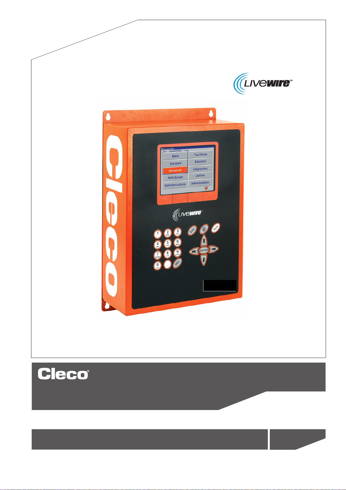
Programming manual
P1934E/EN
2009-04
Electric Tool Control
Serie TMEC-200
Version 2.03.08
For additional product information visit our website at http://www.apexpowertools.com
Page 2

About this programming manual
This programming manual is the – original programming manual – and is intended for all persons
who configure settings on the TMEC-200 controller.
The programming manual does the following:
• It provides important instructions for safe and effective operation.
• It describes the function and operation of the TMEC-200 controller.
• It points out options.
The following documents provide additional information for operating the cordless EC tools with
the TMEC-200 contr
PL12-1405 Parts Manual TMEC-200
P1890E Instruction Manual 17BP
P1891E Instruction Manual 47BA
P1892E Operating instructions Base Station
P1894E Installation instructions
Symbols in the text:
oller:
Cordless
EC toolwith WLAN data transmission
➔ Identifies instructions to
• Identifies enumerations.
italics Identifies menu items, i. e.: Diagnostics
<…> Identifies elements that have to be selected
control boxes, i. e.: <F5>
Courier Identifies the names of paths and files, i. e.: setup.exe
\ A
Disc
laimer:
Apex Tool Group
without prior notice. This document may not be reproduced in whole or in part in any way, shape
or form, or copied to another natural or machine-readable language or to a data carrier, whether
electronic, mechanical, optical or otherwise, without the express permission of
backslash between two names identifies selection of an item from the menu,
i. e.: file \ print
reserves the right to modify, supplement or improve this document or the product
be followed.
o
r deselected, such as buttons or
Apex Tool Group
.
2 P1934E/EN 2009-04 en00c381.fm, 23.04.2009
Page 3

Contents
1 Getting started 7
1.1 Workplace safety symbol...................................................................... 7
1.2 Checking your unit ................................................................................ 7
1.3 Software................................................................................................ 7
1.4 Installing the unit................................................................................... 7
1.4.1 General information .............................................................................. 7
1.4.2 Assembly .............................................................................................. 8
1.4.3 Location considerations ........................................................................ 8
1.4.4 Power source........................................................................................ 8
1.4.5 Intended use ......................................................................................... 8
1.4.6 EMC measures ..................................................................................... 9
1.5 Connecting the unit............................................................................... 9
1.5.1 General information .............................................................................. 9
1.6 Switching on the unit........................................................................... 10
1.7 Communication with cordless EC tool ................................................ 11
1.8 System overview................................................................................. 13
2 Controller specifications 15
2.1 Understanding the keypad .................................................................. 15
2.2 Technical data..................................................................................... 16
2.2.1 Housing............................................................................................... 16
2.2.2 Display ................................................................................................ 16
2.2.3 Keypad overlay ................................................................................... 16
2.2.4 CPU with PC 104................................................................................ 17
2.2.5 AC power supply................................................................................. 18
2.2.6 Internal DC power supply ................................................................... 18
2.2.7 Input / output connectors .................................................................... 18
3 Programming 21
3.1 Navigator Menu .................................................................................. 21
3.1.1 Basic Navigation instructions..............................................................
3.1.2 Password function .............................................................................. 22
3.1.3
3.1.4 Navigator Menu .................................................................................. 22
3.2 Basic Application Builder .................................................................... 24
3.2.1 Basic parameters for torque control / angle monitoring ...................... 25
3.2.2 Basic parameters for angle control / torque monitoring ...................... 25
3.2.3 Basic Application Builder parameters ................................................. 25
3.2.4 Advanced parameter default values ................................................... 26
3.2.5 Basic Application Builder / Copy......................................................... 26
3.3 Standard Application Builder............................................................... 27
3.3.1 Standard Application Builder / View Stages............
Multiple channel functions: General description .................................
............................ 27
21
22
P1934E-EN_2009-04_TMEC200_V2.03.08IVZ.fm, 23.04.2009 P1934E/EN 2009-04 3
Page 4

3.3.2 Standard Application Builder / View Stages / Copy ............................ 28
3.3.3 Standard Application Builder / Select Sequence ................................ 29
3.3.4 Standard Application Builder / Parameters ......................................... 32
3.3.5 Standard Application Builder / Advanced Parameters ........................ 38
3.4 Advanced............................................................................................ 39
3.4.1 Advanced Application Builder / Application Matrix.............................. 39
3.4.2 Advanced Application Builder / Inputs – only for TMEB-200 / TMEC . 40
3.4.3 Advanced Application Builder / Outputs – only for TMEB-200 / TMEC 42
3.4.4 Advanced / Linking ............................................................................. 44
3.4.5 Advanced / System Settings............................................................... 45
3.5 RUN Screen........................................................................................ 48
3.5.1 Run Screen / Configuration ................................................................ 51
3.6 Oscilloscope ....................................................................................... 52
3.7 Communications ................................................................................. 53
3.7.1 Communications / Ethernet ................................................................ 53
3.7.2 Communication / Part ID..................................................................... 58
3.7.3
3.7.4
Communications / Printer ................................................................... 61
Communication / Tool ......................................................................... 62
3.7.5 Infrared data transmission .................................................................. 63
3.7.6
3.7.7
868 MHz data transmission ................................................................ 64
WLAN data transmission .................................................................... 67
3.8 Tool Setup........................................................................................... 73
3.9 Statistics.............................................................................................. 74
3.9.1 Statistics / Chronological History ........................................................ 74
3.9.2 Statistics / Charts ................................................................................ 75
3.9.3 Statistical Parameter........................................................................... 78
3.10 Diagnostics ......................................................................................... 79
3.10.1 Inputs / Outputs – only for TMEB-200 / TMEC ................................... 79
3.10.2 Tool / Tool Memory.............................................................................. 80
3.10.3 Serial................................................................................................... 80
3.11 Utilities ................................................................................................ 81
1.1 Utilities / Software ............................................................................... 81
3.1
3.1
1.2 Utilities / Tool....................................................................................... 82
3.11.3 Utility / System settings – only for TMEB-200 / TMEC ....................... 83
3.12
3.12.1
Administration ..................................................................................... 84
Administration / Load .......................................................................... 84
3.12.2 Administration / Save.......................................................................... 85
3.12.3
3.12.4
Administration / Print........................................................................... 86
Administration / Password .................................................................. 87
3.12.5 Administration / Date & Time .............................................................. 88
3.12.6 Administration / Language .................................................................. 89
3.12.7 Administration / Counters ................................................................... 90
4 Troubleshooting 91
4 P1934E/EN 2009-04 P1934E-EN_2009-04_TMEC200_V2.03.08IVZ.fm, 23.04.2009
Page 5

5 Statistics 97
5.1 Understanding Statistics ..................................................................... 97
5.1.1 The Nature of Variation....................................................................... 97
5.1.2 The Normal Curve .............................................................................. 98
5.1.3 The Procedure .................................................................................... 98
5.1.4 System Improvement........................................................................ 102
5.2 Statistic Symbols............................................................................... 103
6 Glossary 105
P1934E-EN_2009-04_TMEC200_V2.03.08IVZ.fm, 23.04.2009 P1934E/EN 2009-04 5
Page 6

6 P1934E/EN 2009-04 P1934E-EN_2009-04_TMEC200_V2.03.08IVZ.fm, 23.04.2009
Page 7

1 Getting started
!
!
1.1 Workplace safety symbol
This warning sign identifies all notes on safe work practices in this operator's manual,
alerting to hazards to life and health of personnel. Observe these notes and proceed with
ial care in the cases described. Pass all safety instructions on to other operators. In
spec
addition to the safety instructions in these operating instructions, the general local safety
and accident prevention rules must be observed.
Getting started
1
ATTENTION!
The signal word "Attention" identifies all portions of these operating instructions meriting
special attention to ensure that guidelines, rules, hints and the correct work procedures
e observed and to prevent damage to and destruction of the machine and/or parts.
ar
1.2 Checking your unit
Take the time to ensure you have the required peripheral equipment and cables necessary to
setup and run your unit. If you do not have all the necessary items, contact your distributor.
Refer to Attachment A.1, page 12 for illustration of your unit.
1.3 Software
Your unit has been pre-loaded with software version 2.03.08 and requires no additional software
to begin your fastening process. If you are interfacing your unit with an external computer, interfacing software is required. Contact your distributor for the interfacing software.
1.4 Installing the unit
1.4.1 General information
It is mandatory that national, state and local safety and wiring standards be followed during installation. These standards take precedence over any information presented in this
ion.
sect
To avoid the hazard of electrical shock or burn, the following instructions must be
red to. Failure to follow these instructions may also cause damage to your unit and
adhe
void existing warranties.
• Do not energize the unit until all connections have been properly made.
• Equipment must be properly grounded before applying power. Units energized by cord
be connected to an approved and properly grounded receptacle.
ATTENTION!
and plug must
• All units must be energized by an isolated line.
• The unit door must always be closed and secured prior to energizing the unit.
• Ensure the power switch is in the "off" position prior to connecting the power cord.
•
Though it is not mandatory, the following instructions are highly recommended for the
protected operation of your unit.
• Use an isolation transformer and surge arrestor on the incoming isolated line.
• Use oversized feeder lines to reduce electrical noise and voltage drop.
en01c381.fm, 23.04.200 9 P1934E/EN 2009-04 7
Page 8

Getting started
1
1.4.2 Assembly
Each unit is used primarily as a single or multiple tool process/controller/monitor installed in a
work station or work area. It may be wall mounted, table mounted, beam mounted, suspended
overhead, pedestal mounted or used without mounting. Always choose a stable location to avoid
the possibility of unit damage and/or operator injury through hitting, falling, vibration or inconvenient mounting. All cables attached to the unit sho
cause injury to the operator or to passersby. Like all electrical devices, the control system emits
some heat. It should therefore be positioned where air can circulate freely around the housing.
Refer to Illustration "J" of the parts manual PL12-1405 for mounting hole dimensions.
1.4.3 Location considerations
Your unit should be located to allow access to the front panel and connectors. The unit should be
installed for unrestricted and comfortable viewing of the LCD screen by the operator. The LCD
menu screen, key pad and connectors must be readily accessible for the setup. Dependent on
the peripheral equipment purchased, the unit may be located in a remote position but should still
be accessible.
Attachment of accessories and tools should also be
Items to be considered are:
• Location of printer.
• Attachment of a data collection unit, if desired.
• Attachment of remote annunciators, socket nest, or remote pa
• Attachment of the unit in a network to a computer.
• Operation convenience/safety - keep cables off the floo
uld b
e located and secured so that they cannot
con
sidered with the installation locations.
rameter select.
r or dangling in operator areas.
1.4.4 Power source
The device acts as process control and power supply unit for Cleco electric nutrunners and
requires a power supply connection of
• 10 A at 115 VAC ±5% (50/60 Hz) or 220 to 240 VAC ±5% (50/60 Hz).
1.4.5 Intended use
The TMEC-200 may be used only under the following conditions:
• Industrial EMC limit value class A.
• Only cables of types authorized by Apex Tool Group
• Furthermore, only accessory parts authorized by Apex Tool Group
• Unauthorized alterations, repairs and modifications are prohibited for reasons of safety and
product liability.
may be used.
may be used.
8 P1934E/EN 2009-04 en01c381.fm, 23.04.2009
Page 9

1.4.6 EMC measures
!
• The filters required to satisfy the EMC regulations are built into the unit.
• The sealed control cabinet and shielded cable prov
and radiated interference.
• The tool complies with the following applicable EMC standards:
-EN 61000-3-2
-EN 61000-3-3
-EN 61000-6-2
-EN 61000-6-4
This is a Class A device. The device may cause signal interference; in this case, the
•
operator may be required to implement suitable EMC measures.
• It is prohibited to operate the unit unless the control cabinet is closed.
The properties of the shielding would change and the noise emission would increase.
1.5 Connecting the unit
1.5.1 General information
Getting started
1
ide very good protection against irradiated
Connect all equipment to the correct input and output connectors. Refer to Attachment A.1,
page 12 for proper port locations.
To avoid the hazard of electrical shock or burn, the following instructions must be
adhered to. Failure to follow these instructions may also cause damage to your unit and
void existing wa
• Ensure that the power switch is in the off
secured prior to connecting the power cord.
• Ensure equipment has been properly grounded before applying power.
rranties.
position and that the box cover is properly
en01c381.fm, 23.04.200 9 P1934E/EN 2009-04 9
Page 10
Getting started
!
1
1.6 Switching on the unit
To avoid the hazard of electrical shock or burn, the following instructions must be
adhered to. Failure to follow these instructions may also cause damage to your unit and
void existing warranties.
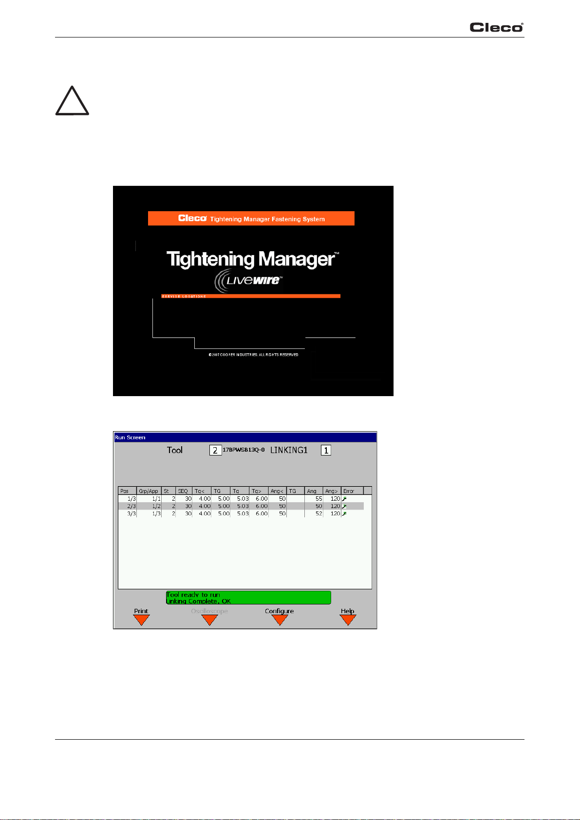
Upon application
45 seconds.
The introduction screen shown below will be displayed
the Run Screen appears.
Fig. 1-1: Introduction screen
of power, the
unit will initiate a self tes
t. The initialization takes approximately
for approximately 10 seconds, after which
c00276de.bmp
c00289de.bmp
Fig. 1-2: RUN screen
10 P1934E/EN 2009-04 en01c381.fm, 23.04.2009
Page 11

1.7 Communication with cordless EC tool
Before initial operation of the tool, ensure that the battery is securely in place.
After you press and release the start button, the LCD display reads Ready. Th
for communication. Place it in the tool holder.
Click on the ship's wheel (Navigator button) again to display the Navigator Menu. Call up the
mmun
Co
Tool not connected... warning message.
ication - Tool screen to register the tool with the connected interface, acknowledging the
Getting started
1
e tool is now ready
Under Co
the tool. Press softkey <F1>, Accept. When the tool is switched on and connected, the tool serial
number will be shown in the Connected tool field. Press softkey <F2>, Assign. For a detailed
description, refer to 3.7.4 Communication / Tool, page 62.
Press the ship's wheel again to display the Navigator Menu.
Verify and acknowledge Tool Memory by entering Tool Se
the Navigator Menu.
Once Tool Setup is complete the application
Application Builder.
In this screen, torque, angle, and speed parameters must be entered for the selected application.
Press the ship's wheel again to return t
Now call up Run Scr
Tool ready is displayed in the status line. The display on the tool lights up green. The tool is now
ready to begin the first fastening cycle.
You can view the torque and angle data by pressing Run
play and the indicator lights on the tool show current results.
If you leave the tool on and place it in the tool h
system and are displayed in the Run Screen.
mmunication with the Tool, se
een. Provided the tool is switched on and in the tool holder, the message
lect the interface you want to use for communication with
p. Press the ship's wheel to return to
tu
needs to be programmed. To do this, go to Basic
o
the Navigator Menu.
Scr
een. As you work, the screen dis-
o
lder, the results are transmitted to the control
en01c381.fm, 23.04.200 9 P1934E/EN 2009-04 11
Page 12
Getting started
1
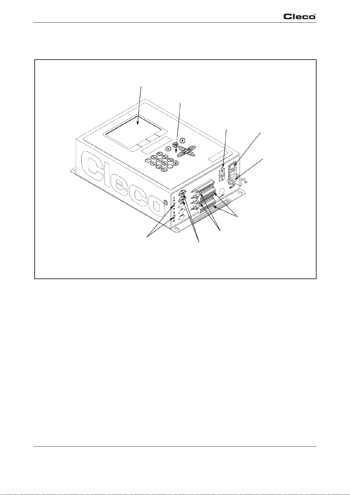
Attachment A.1
LCD display
Key pad
Fig. 1-3: Controller
USB Ports
Serial Ports
Ethernet Port
I/O inputs
Fuse holder
Power In
I/O outputs
a00729
12 P1934E/EN 2009-04 en01c381.fm, 23.04.2009
Page 13
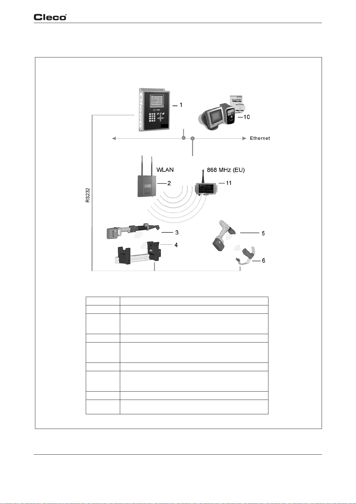
1.8 System overview
Getting started
1
Alternatives
Item Designation
1 TMEC-200 – Controller for electric nutrunner
2 Access point –
Order no. 543995 (NA)
Order no. 961323 (EU)
3 Tool series 47BAW…, 47BAX…, 47BAR…
4 Tool holder
Order no. 935290 – with IrDA interface, RS232 connection cable
Order no. 935395 – without IrDA interface, RS232 connection cable
5 Tool series 17BPW…, 17BPX…, 17BPR…
6 Tool holder
Order no. 935144 – with IrDA interface, RS232 connection cable
Order no. 935396 – without IrDA interface, RS232 connection cable
10 TMEB-COM – Computer with PC software
11 Base station
Order no. 961300 – 868 MHz (EU)
en01c381.fm, 23.04.200 9 P1934E/EN 2009-04 13
Overview EC TMEC
Page 14

Getting started
1
14 P1934E/EN 2009-04 en01c381.fm, 23.04.2009
Page 15
2 Controller specifications
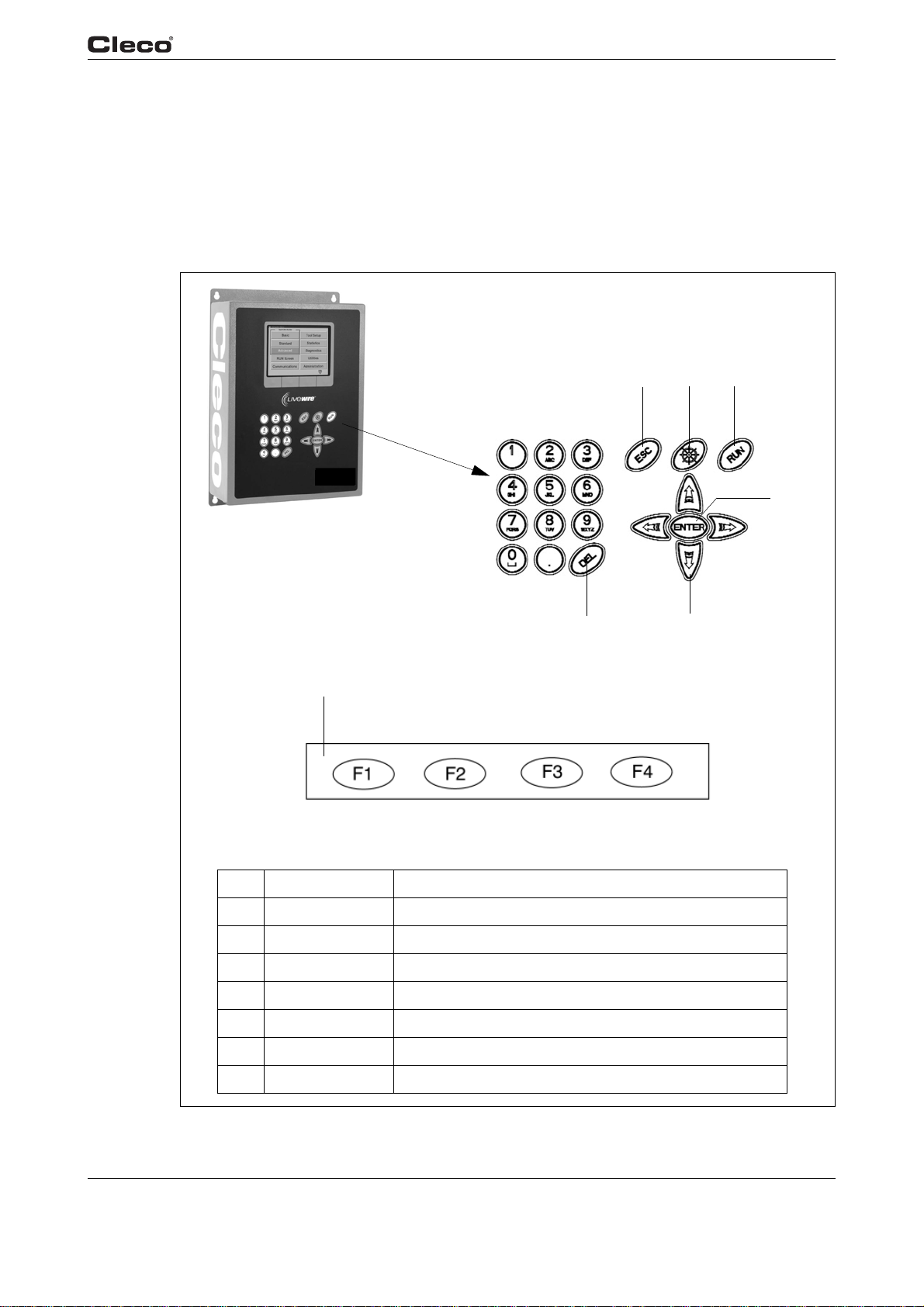
2.1 Understanding the keypad
The following is a brief explanation of the keypad keys. You will need to become familiar with
these keys so you can smoothly program your unit.
Controller specifications
2 3
1
2
6
7
Pos. Key Function
1 ESC to leave Edit mode.
2 Ship's wheel used at any time to return to the navigator menu.
3 RUN used to return at any time to Run Screen.
4 ENTER used to accept an answer/value on the LCD screen.
5 Arrow keys used to move the orange highlight around the screen.
6 DEL used to delete a numerical value on the LCD screen.
5
4
7 Softkeys (F1-F4) used to select functions based on the screen displayed.
en02c381.fm, 23.04.200 9 P1934E/EN 2009-04 15
Page 16
Controller specifications
2
2.2 Technical data
2.2.1 Housing
The TMEC-200 housing is enclosed with no front door. The controller can be opened by removing from the wall and removing the back plate. All I/O connector are on the bottom of the enclosure.
Model Weight Width Height Depth
TMEC-200 13 5,9 11 279,4 17 431,8 5 127
2.2.2 Display
• Color LCD modules
• 640 x 480 resolution
• CCFT backlight
• Contrast and Brightness control
lb kg in mm in mm in mm
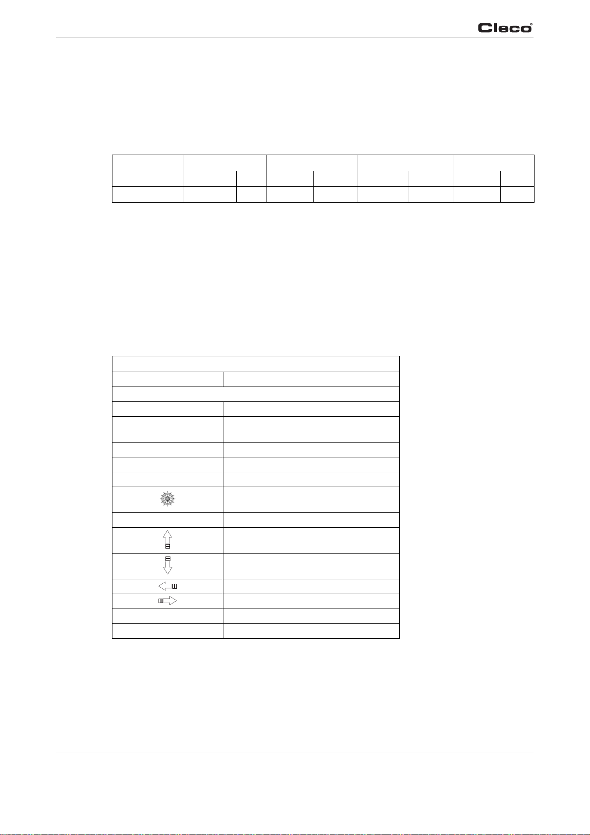
2.2.3 Keypad overlay
Key Description
0 – 9 Numbers 0 – 9
Letters A – Z Included on numeric buttons 2 through 9
. Decimal point
DEL Delete
ESC Escape
RUN Run Screen
ENTER Enter
Orange field 4 Softkeys
Key definitions
(cell phone style)
Navigator Menu
Up Arrow
Down Arrow
Left Arrow
Right Arrow
16 P1934E/EN 2009-04 en02c381.fm, 23.04.2009
Page 17

The alpha-numeric keys (2 – 9) are context sensitive: only numbers are available for fields that
require only numerical input, and alphabetical and numeric entries are possible for text fields.
In text fields the key scrolls thro
key. For example, the <2abc> button in a numeric field will only provide the number 2.
In a text field, the 1st press will be "A" (capital), the 2nd press will toggle to "a"
3rd press toggles to "B", 4th press "b", 5th press "C", 6th press "c", 7th press "2", and then recycles back to "A". Once you have toggled
the next character.
2.2.4 CPU with PC 104
Minimum requirements
• Pentium 166 Mhz
• 32 MB DRAM
• 32 MB DiskonChip
• 2 serial ports
• 1 parallel port
• Ethernet 100-Base T
• PC Keyboard input
• PC/104 Bus
• Floppy interface
• LCD/Flat Panel controller
• 2 USB ports
Controller specifications
2
ugh the letters and number with each successive press of the
(lower case), the
to the character required, move to another key to input
en02c381.fm, 23.04.200 9 P1934E/EN 2009-04 17
Page 18

Controller specifications
2
Arcnet PC/104 board
• Arcnet communication
•4 +24 V inputs
•12 +24 V outputs
• 24-position keypad decoder
• Battery-Backed SRAM, 1 MB
External I/O PC/104 board
• 8 optically isolated inputs
• 8 relay outputs
2.2.5 AC power supply
90 – 264 VAC AC input power,
47 – 63 Hz single phase,
< 5 A at minimum input voltage.
2.2.6 Internal DC power supply
• Primary: 90 – 264 VA C , 4 7 – 63 Hz single phase
• Secondary: +5 VDC, 5 A; +12 VDC, 1 A; +24 VDC, 3 A; ±5% at all voltages
•65 W capability without a fan
•MTBF -> 20,000 hours
2.2.7 Input / output connectors
Serial (2) 9-pin Male D-Shell
Inputs (+24 V) Phoenix MSTBV 2.5/12-GF-5.08 Order No. 1777170
Outputs Phoenix ICV 2.5/12-GF-5.08 Order No. 1825792
USB 2 each
Ethernet RJ45
AC Input Power Cold device plug
18 P1934E/EN 2009-04 en02c381.fm, 23.04.2009
Page 19

Controller specifications
Serial
Pin # Description Value
1 DCD -25V.. +25 V
2 RxD -25V.. +25 V
3 TxD -25V.. +25 V
4 DTR -25V.. +25 V
5 Signal Ground 0 V
6 DSR -25V.. +25 V
7 RTS -25V.. +25 V
8 CTS -25V.. +25 V
9 RI -25V.. +25 V
Parallel
Pin # Description Value
1 Strobe 0.. +5 V
2 Data 0 0.. +5 V
3 Data 1 0.. +5 V
4 Data 2 0.. +5 V
5 Data 3 0.. +5 V
6 Data 4 0.. +5 V
7 Data 5 0.. +5 V
8 Data 6 0.. +5 V
9 Data 7 0.. +5 V
10 Acknowledgment 0.. +5 V
11 Busy 0.. +5 V
12 Paper Out 0.. +5 V
13 Select Out 0.. +5 V
14 Auto Feed 0.. +5 V
15 Error 0.. +5 V
16 Initialize 0.. +5 V
17 Select In 0.. +5 V
18 Signal Ground 0 V
19 Signal Ground 0 V
20 Signal Ground 0 V
21 Signal Ground 0 V
22 Signal Ground 0 V
23 Signal Ground 0 V
24 Signal Ground 0 V
25 Signal Ground 0 V
2
en02c381.fm, 23.04.200 9 P1934E/EN 2009-04 19
Page 20

Controller specifications
2
Keyboard
Pin # Description Value
1 Data 0.. +5 V
2 nc N/A
3 Signal Ground 0 V
4 Power supply 0.. +5 V
5 Clock 0.. +5 V
Inputs
Pin # Description Value
1 +24 V (Output) +24 VDC
2 Input 0 0.. +24V
3 Input 1 0.. +24V
4 Input 2 0.. +24V
5 Input 3 0.. +24V
6 Input 4 0.. +24V
7 Input 5 0.. +24V
8 Input 6 0.. +24V
9 Input 7 0.. +24V
10 Input Common (Input) 0 V
11 Signal Gnd (Output) 0 V
12 Spare N/A
For signal description please see chapter 3.4.2 Advanced Application Builder / Inputs – only for
TMEB-200 / TMEC, page 40.
Outputs
Pin # Description Value
1 +24 V (Output) +24 VDC
2 Output Common (Output) 0.. 30 V
3 Output 0 0.. 30 V
4 Output 1 0.. 30 V
5 Output 2 0.. 30 V
6 Output 3 0.. 30 V
7 Output 4 0.. 30 V
8 Output 5 0.. 30 V
9 Output 6 0.. 30 V
10 Output 7 0.. 30 V
11 Signal Gnd (Output) 0 V
12 Spare N/A
For signal description please see chapter 3.4.3 Advanced Application Builder / Outputs – only for
TMEB-200 / TMEC, page 42.
20 P1934E/EN 2009-04 en02c381.fm, 23.04.2009
Page 21
3 Programming
3.1 Navigator Menu
Programming
3
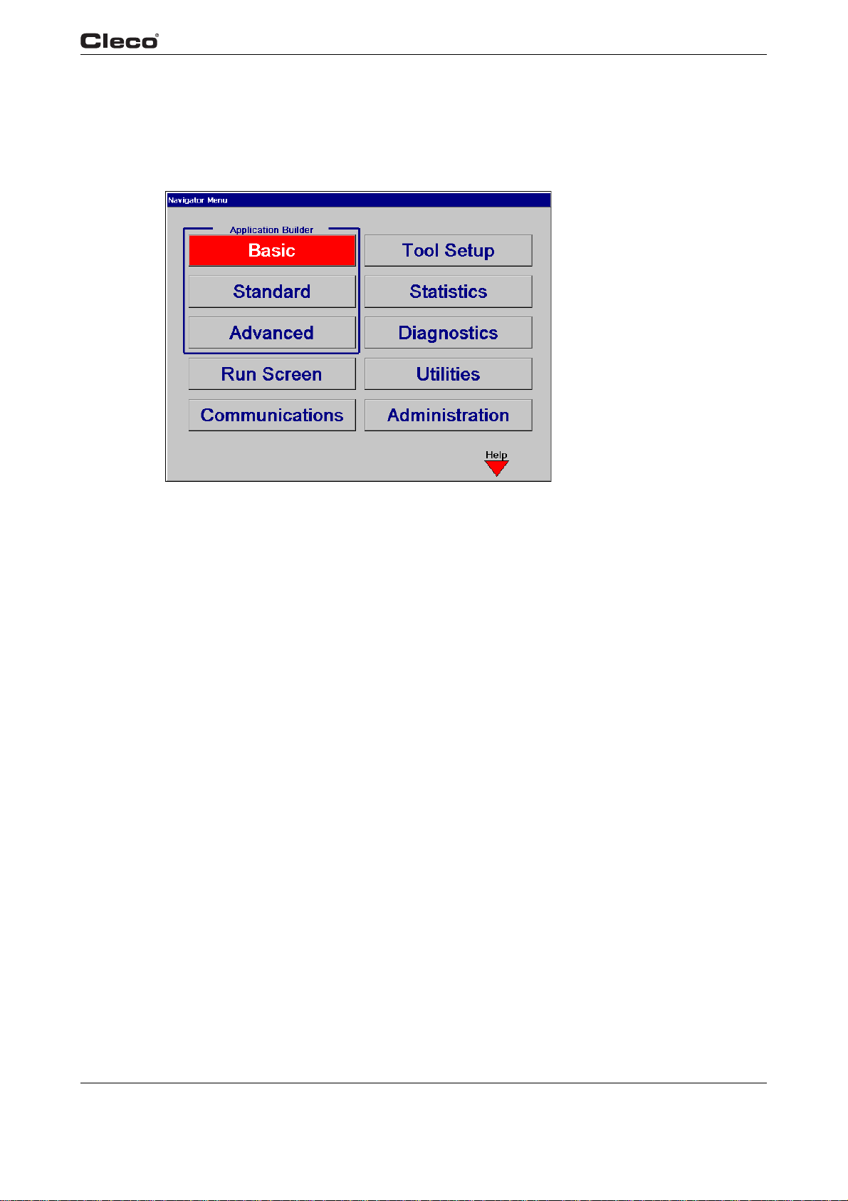
Fig. 3-1: Navigator Menu
nav.txtS
3.1.1 Basic Navigation instructions
Each field in a screen can be selected by highlighting with the orange cursor, using the 4 arrow
keys and Enter. Upon entering a screen the top left most field is always highlighted. The Navigator key (ship's wheel) will always return the user to the Navigator
screen 4 Softkeys are available. These functions will change from screen to screen. In some
cases, the character >> appears for a button on the screen, meaning that this button can be used
to call up additional functions.
To edit a text box, the user can use 0-9 or the DEL
the arrow keys to move the highlight or press the ESC key. The ESC key will return the original
value.
In order to describe the Softkey functions the left Softkey is referred to as F1, center left Softkey
, center right Softkey F3 and right Softkey F4. They are all displayed inside an orange frame.
F2
F4 always functions as Help for that screen.
You may select from 1-255 applications. When you inpu
2 digits (1-99), a cursor flashes in the processing field. The number is adopted either when you
press <ENTER> or automatically after 3 seconds. A three-digit application number (100-255) is
accepted as soon as the third digit is entered.
Stages 1-6 are selectable.
Menu. At the bottom of the
ke
ys. To exit the edit mode the user can press
t an application number consisting of 1 or
c00277en.bmp
en03c381.fm, 23.04.200 9 P1934E/EN 2009-04 21
Page 22

Programming
3
3.1.2 Password function
If the user exits a section with programmable data (Basic, Standard, Advanced, Communications, Tool Setup) that has been changed, then the pa
password is activated, then only the confirm entry in the password dialog is displayed. Once the
password has been entered, it must be entered each time an appropriate screen is exited.
Print screen
A Print Screen function is available on all screens. In s
been added that allows you to save the bitmap to a removable storage media, the hard drive or
send it directly to a printer (Laser, Inkjet). On screens that do not have this Softkey, the user can
reach this function by pressing the <0> key. A dialog box allowing the user to assign a file name
will be displayed. Using the arrow keys, highlight the file name and enter up to 8 characters, then
activate Accept to save to the selected drive.
3.1.3 Multiple channel functions: General description
The user interface is identical to the multichannel configuration. All screens display the data for
the currently selected tool. Select the current tool by entering the tool number in the Too l edit
field. The tool can be selected using the Run Screen, the Basic Application Builder, the Standard
Application Builder or the Statistics screen. In views that do not permit a change in tool selection,
the current tool is displayed in the blue title bar at the top of the screen. Any tool may be used at
any time, regardless of which tool is currently selected via the user interface.
ssword entry dialog will be displayed. If no
ome cases a Print Screen Softkey has
Any adjustable parameter can be set and stored independently for each tool, with the following
ceptions:
x
e
• Language
• Password
• Torque Units
• Run Screen Auto-select
• Ethernet protocol, IP addresses and port numbers
• System settings/General, optional: Same
(see Extended/System settings)
he following restrictions apply for multichannel mode:
T
• The automatic selection function does not apply to the
3.1.4 Navigator Menu
Basic Application Builder
The Basic Application Builder allows you to select and program a two-stage rundown for Torque
Control
(Sequence 11/Sequence 50) for any of the available 255 Applications. The user only enters
Torque, Angle, and Speed setpoints in one screen. Other parameters such as timers, etc. are
automatically defaulted to predetermined values.
/Angle Monitoring (Sequence 11/Sequence 30) or Angle Control/Torque Monitoring
for all tools
oscilloscope display.
Standard Application Builder
Via the Standard Application Builder, the user can program a rundown of up to 6 stages for any of
255 Applications. Once the fastening sequence has been selected for each stage, the corre-
the
sponding Torque, Angle, Speed and Advanced Parameters can be programmed.
22 P1934E/EN 2009-04 en03c381.fm, 23.04.2009
Page 23

Programming
Advanced Application Builder
The Advanced Application Builder allows the
at once, the I/O assignment for inputs and outputs, the configuration of a field bus interface, the
configuration of fastening sequences (step counter) and changes in system settings that define
monitoring of execution.
RUN Screen
The Run Screen button takes the user directly to the d
tor Labels. The Oscilloscope function used for diagnos
Run Screen.
Communications
The Communication Settings option allows the user to config
the printer and serial data transmission. The corresponding communication settings for protocol,
port, baud rate, etc. can be defined at this screen.
Tool Setup
The Tool Setup screen displays the data in tool memory. You can edit this data or select settings
from the T
Statistics
Chronological History and associated
erased and printed as well.
ool Library.
statistics are viewable from this screen. Data can be
user to display all of the Application configurations
isplay for Torque, Angle, and Status Indica-
ing torque traces is also located in the
ure all communication for the tool,
3
nav.txtE
Diagnostics
The System Diagnostics contains screens to determine if th
There are diagnostics screens available for I/O, Tool Memory and serial communications.
Utilities
Utilities contains functions for upgrading or changing the s
screen, you can update the TMEB application software from a diskette or install a new Firmware
version in the tool.
Administration
From the Administration screen, the user can load
Administration functions include loading the system configuration or saving it to a diskette, setting the date and time, setting password protection, printing the syst
ing the language for the application software (English, German).
, save and configure system information.
e system is functioning properly.
ystem software. From the Utilities
em configuration and select-
en03c381.fm, 23.04.200 9 P1934E/EN 2009-04 23
Page 24
Programming
3
3.2 Basic Application Builder
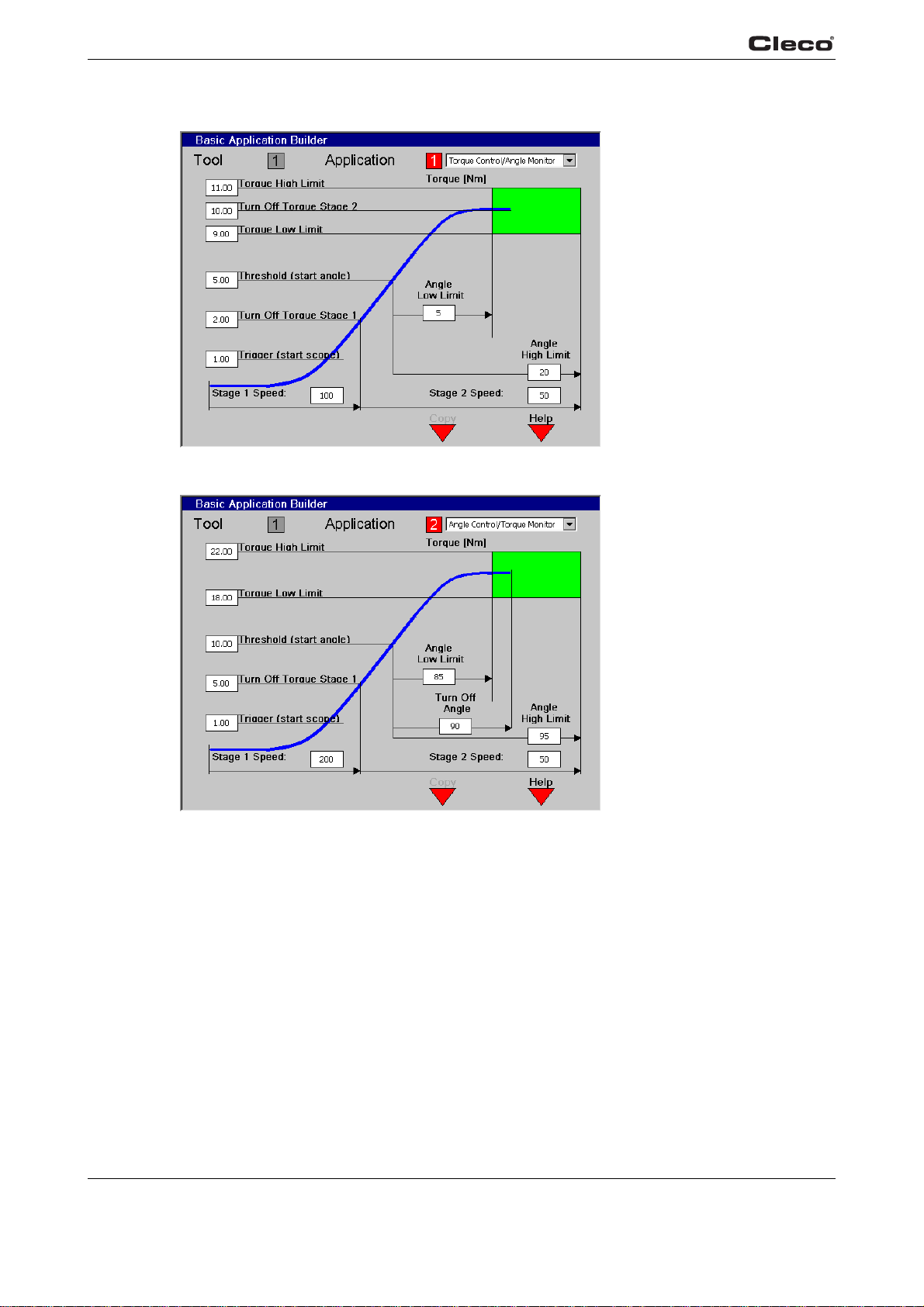
Fig. 3-2: Torque Control/Angle Monitoring
c00278en.bmp
Fig. 3-3: Angle Control/ Torque Monitoring
Basic.txtS
24 P1934E/EN 2009-04 en03c381.fm, 23.04.2009
The Basic Application Builder allows you to program a typical two-stage sequence. The first
stage controls fastening at high speed, and the second controls final tightening at low speed with
either torque or angle shut-off.
Fastening Strategies Torque Control/Angle Monitori
Control/Torque Monitoring (Sequence 11/Sequence 50) are selectable from the dropdown listbox
in the upper right hand corner of the screen. Once a Strategy is selected, the appropriate
Parameters will be displayed for programming.
ng (Sequence 11/Sequence 30) or Angle
c00279en.bmp
Page 25

3.2.1 Basic parameters for torque control / angle monitoring
• Trigger Torque [Nm] - Torque to start collecting oscilloscope data.
• Turnoff Torque Stage 1 [Nm] - Torque to change from stage 1 to stage 2.
• Threshold Torque [Nm] - Torque to begin counting angle in stage 2.
• Torque Low Limit [Nm] - Minimum acceptable torque.
• Turnoff Torque Stage 2 [Nm] - Torque to turnoff the tool.
• Torque High Limit [Nm] - Maximum acceptable torque.
• Angle Low Limit [Deg] - Minimum acceptable angle.
• Angle High Limit [Deg] - Maximum acceptable angle.
3.2.2 Basic parameters for angle control / torque monitoring
• Turnoff Angle [Deg] - Angle to turnoff the tool.
• The rest of the Parameters are the same as To
Torque Stage 2 is eliminated.
Below are the acceptable ranges for each Paramete
ming, the Parameters automatically u
se the default values.
rque Control/Angle Monitoring except Turnoff
r an
d its default values. For initial program-
Programming
3
3.2.3 Basic Application Builder parameters
Parameter name Range Typical
Fastening strategy Torque control / angle monitoring;
angle control / torque monitoring
Trigger Torque [Nm] 0 to Tool Max 10% of Turnoff Torque
Turnoff Torque Stage 1 [Nm] 0 to Tool Max As appropriate
Threshold Torque [Nm] 0 to Tool Max 50% of Turnoff Torque
Torque Low Limit [Nm] -tool maximum value* to tool
a
maximum v
Turnoff Torque Stage 2 [Nm] Low Limit to Tool Max. As appropriate
Torque High Limit [Nm] Turnoff to 1.2 TQ-Cal. value 110% of Turnoff Torque
Angle Low Limit [Deg] 0 to 9999 90% of Turnoff Angle
Turnoff Angle [Deg] Low Limit to 9999 As appropriate
High Angle Limit Turnoff to 9999 110% of Turnoff Angle
Speed Stage 1 [RPM] 0 to Tool Max 80% of Tool Max
Speed Stage 2 [RPM] 0 to Tool Max 50
* Note: To input a negative value for Low Torque, you must enter two dots “..” in front of the value
lue
Angle control / Torque Monitoring
90% of Turnoff Torque
In the Basic Application Builder some parameters are not programmable and are also set to
fault values. These values are located in the Standard Application Builder under Advanced
de
Parameters. However, if the parameters are changed using the Standard Application Builder,
then the Basic Application Builder does not reset them back to the default values.
en03c381.fm, 23.04.200 9 P1934E/EN 2009-04 25
Page 26
Programming
3
3.2.4 Advanced parameter default values
Parameter name Stage 1 Stage 2
Start delay time [mS] 0 0
Start spike time [mS] 0 0
Max. fastening time [ms] 10000 10000
End delay time [mS] 0 30
Torque Filter Factor 1 1
If an Application with more than two stages is required, or if a different Fastening Strategy is to be
selected for the Application than the one described above, you must use the Standard Application Builder.
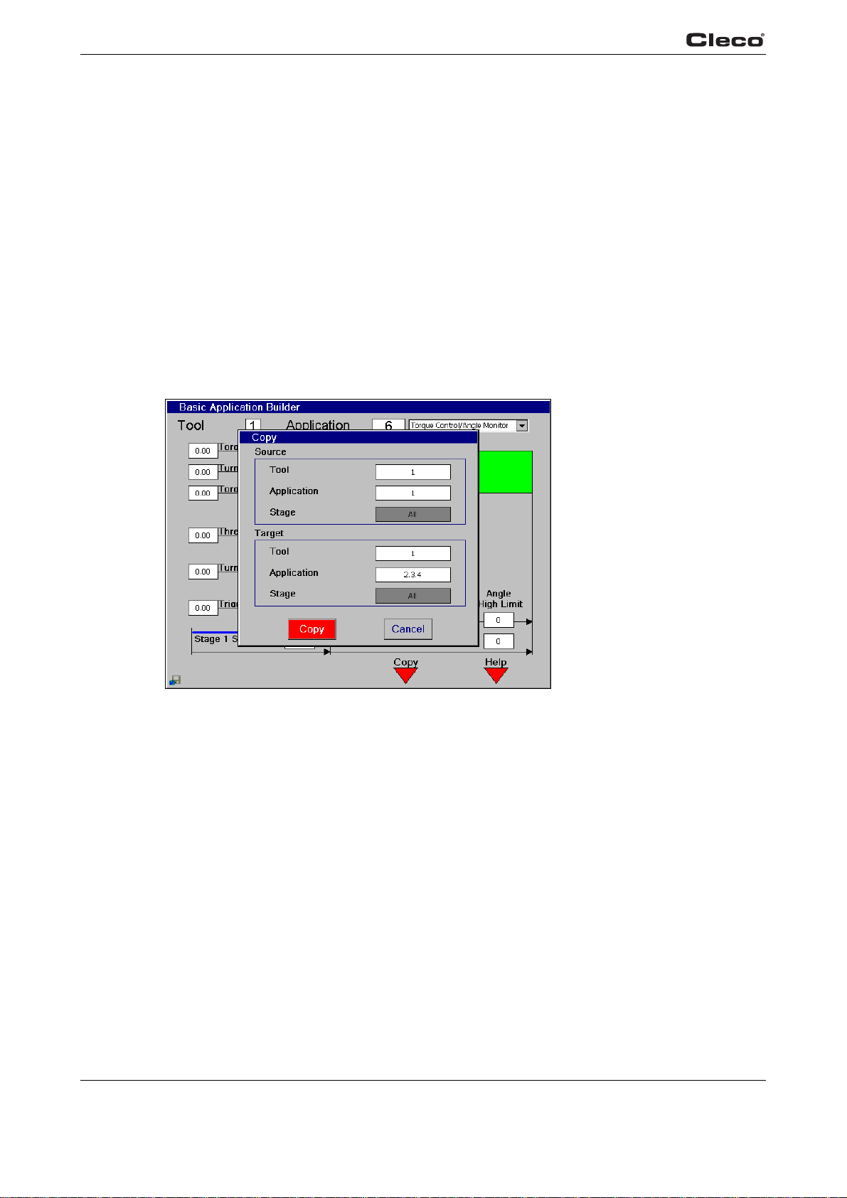
3.2.5 Basic Application Builder / Copy
Fig. 3-4: Copying
Using the Basic Application Builder, you can copy the parameters from one Application to
another by pressing the <F3> softkey. This dialog box allows you to specify the source tool, the
target tool and the Application. When you use the copy function in the Basic Application Builder,
all the stages for the selected Application are copied. You can specify multiple target Applications; to do so, separate the numbers for
Basic.txtE
26 P1934E/EN 2009-04 en03c381.fm, 23.04.2009
each App
lication with a dot as shown.
c00362en.bmp
Page 27
3.3 Standard Application Builder
3.3.1 Standard Application Builder / View Stages
Programming
3
viewstag.txtS
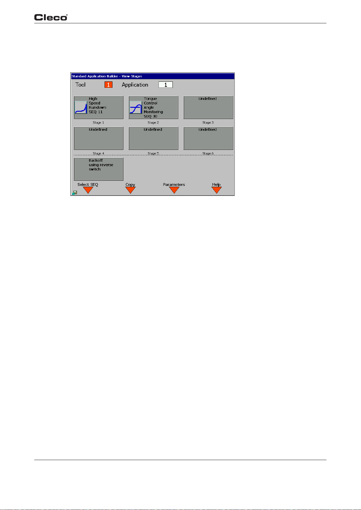
Fig. 3-5: View Stages
From View Stages, you can program Stages 1-6 and a Backoff Stage for a given tool and application.
When the tool is started, each Stage having a programmed Fas
succession based on the results from the previous stage. The Backoff Stage is used when the
tool is run in back-off direction or with the reverse button activated.
If a sequence has not been selected for a stage, then N/A is dis
the Sequence number, description and icon are displayed. Sequences can be selected or
changed using the Select Seq <F1> Softkey. This key is only valid when stages 1-6 are high-
f
lighted. The Fastening Sequence for the Backof
The parameters for any stage can be programmed using the Para
is only valid when a Sequence has been selected for a given Stage.
Stage is selected automatically.
tening Sequence will be run in
played for that stage. Otherwise
meters <F3> Softkey. This key
c00280en.bmp
en03c381.fm, 23.04.200 9 P1934E/EN 2009-04 27
Page 28
Programming
3
3.3.2 Standard Application Builder / View Stages / Copy
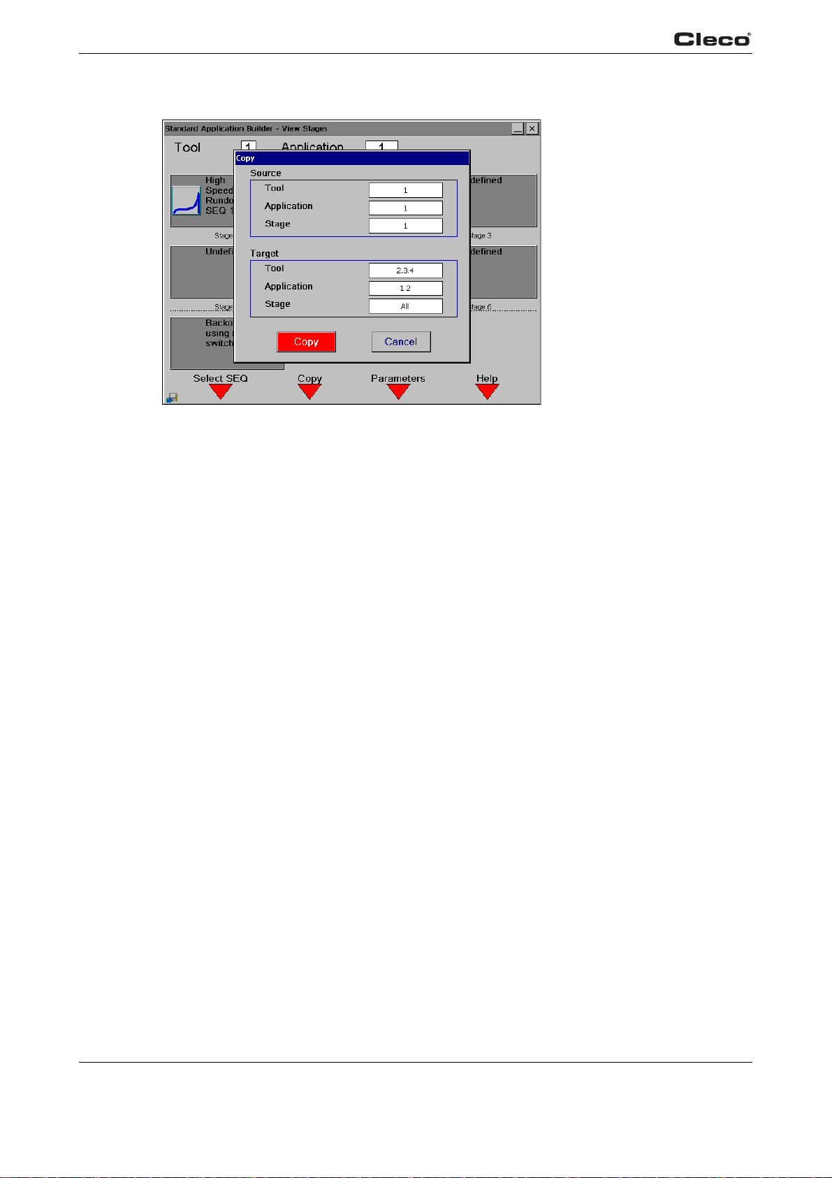
Fig. 3-6: Copying
c00366en.bmp
viewstag.txtE
From the Standard Application Builder, the user can press the Copy <F2> softkey to copy the
parameters for an Application or Stage to one or more other Applications or Stages. From this
dialog box, the user can specify the source and target tools, the Application and one or all
Stages. A single Stage can be copied to several Applications and/or Stages. You can specify
multiple target Applications and Stages; to do so, separate the numbers for each with a dot as
shown.
28 P1934E/EN 2009-04 en03c381.fm, 23.04.2009
Page 29
3.3.3 Standard Application Builder / Select Sequence
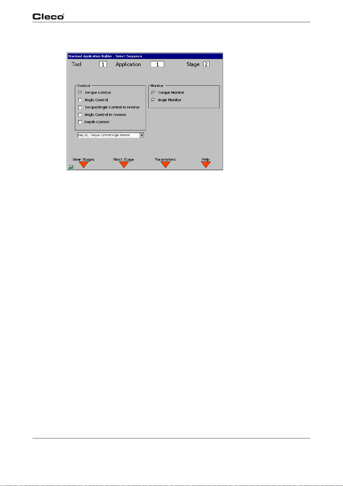
Fig. 3-7: Select Sequence
Programming
3
c00281en.bmp
selectse.txtS
For a given Tool, Application and Stage, you can select a Fastening Sequence by using the
Control and Monitor check boxes or by selecting directly from the dropdown listbox.
The following Fastening Sequences or Fastening Strategies are available:
Sequence 11 High Speed Rundown
ntro
Sequence 16 Depth Sensor/Angle Co
Sequence 30 Torque Control/Angle Monitoring
Sequence 50 Angle Control/Torque Monitoring
Sequence 41 Angle Controlled Backoff
When a Sequence is selected the Control and Monitor check boxes and Fastening Sequence
listbox will
the selected Sequence is also displayed in the bottom right-hand corner.
both display the appropriate settings for the selected Sequence. An icon portraying
l/Torque Monitoring
en03c381.fm, 23.04.200 9 P1934E/EN 2009-04 29
Page 30

Programming
3
The following table shows a matrix of the Control and Monitor schemes for each Sequence:
Sequence 11 Sequence 16 Sequence 30 Sequence 50 Sequence 41
Control
Torque Control X X
Angle Control x X
Angle Control in Reverse X
Monitor
Torque Monitoring x X X
Angle Monitoring x X X X
The Parameters <F3> Softkey allows the user to program all associated control parameters for
the selected Sequence. It is only valid when a Sequence has been selected.
The following is a detailed description of each Fastening Sequence:
Sequence 11
High Speed Rundown
This tightening method is generally used as a fast pr
e-tightening stage. The torque transducer
integrated into the nutrunner measures the torque during the tightening. The value is processed
by the control system. When the defined Turnoff Torque is reached the nutrunner is shut off.
Thereafter the peak torque is measured during a dwell time and is then processed as the tightening torque of the bolt in the control system. This valu
e is displa
yed on the Run Screen and can be
output to a printer or transmitted to other system components by data communication. When the
trigger torque is reached the torque curve is recorded and can be viewed and evaluated using
the oscilloscope function.
Sequence 16
Depth sensor, Angle Control with Angle and Torque Monitoring
st pr
This tightening method is generally used as a fa
e-tightening stage. During fastening, the
depth sensor built in to the tool generates a signal at the preset insertion depth. This signal is
processed by the control system. At the start of the Stage, the system checks to see if the signal
is activated. If it is, the error TS is set for Depth Sensor error. When the programmed insertion
depth is reached, the nutrunner switches to angle control with angle and torque monitoring.
When the Turnoff angle is reached the nutrunner is shut off. Thereafter the peak torque is mea-
tightening torque of the bolt in the control
sured during a dwell time and is then processed as th
e
system. This value is displayed on the Run Screen and can be output to a printer or transmitted
to other system components by data communication. When the trigger torque is reached the
torque curve is recorded and can be viewed and evaluated using the oscilloscope function. The
depth signal is monitored for all further Stages. If the depth signal is deactivated as the rundown
proceeds, the error TS is set.
Sequence 30
Torque Control with Torque and Angle Monitoring
a
This tightening sequence is generally preceded by
fast pre-tightening cycle. The transducer
integrated into the nutrunner measures the torque and the resolver measures the angle during
the tightening. The values are processed by the control system. When the threshold torque is
reached the angle count starts. When the defined Turnoff Torque is reached the nutrunner is shut
off. Thereafter the peak torque is measured during a dwell time and is then processed as the
tightening torque of the bolt together with the evaluation of the rundown in the control system.
This value is displayed on the Run Screen and can be output to a printer or transmitted to other
system components by data communication. When the trigger torque is reached the torque curve
is recorded and can be viewed and evaluated using the oscilloscope function.
30 P1934E/EN 2009-04 en03c381.fm, 23.04.2009
Page 31

selectse.txtE
Programming
Sequence 50
Angle Controlled Tightening with Angle and Torque Monitoring
This tightening sequence is generally preceded by a
integrated into the nutrunner measures the torque and the resolver measures the angle during
the tightening. The values are processed by the control system. When the Turnoff angle is
reached the nutrunner is shut off. Thereafter the final angle and the peak torque are measured
during a dwell time, and these tightening values for the bolt are then processed together with the
evaluation of the rundown in the control system. These values are displayed on the Run Screen
and can be output to a printer or transmitted to other system components by data communication. When the trigger torque is reached the torque curve is recorded and can be viewed and
aluated using
ev
Sequence 41
Angle Controlled Back-off with Angle Monitoring
This fastening sequence is generally used to loosen a bo
resolver integrated into the nutrunner measures the angle during the backoff. The value is processed by the control system. When the Turnoff angle is reached the nutrunner is shut off.
eafter the final angle is measured during a dwell time and is then processed as the back-off
Ther
angle of the bolt together with the evaluation of the backoff in the control system. This value is
displayed on the Run Screen and can be output to a printer or transmitted to other system components by data communication. In this stage
the oscilloscope function.
fast pre-tightening cycle. The transducer
lt a specified number of degrees. The
the osc
illoscope function is not supported.
3
en03c381.fm, 23.04.200 9 P1934E/EN 2009-04 31
Page 32
Programming
3
3.3.4 Standard Application Builder / Parameters
Fig. 3-8: Parameters
c00282en.bmp
paramete.txtS
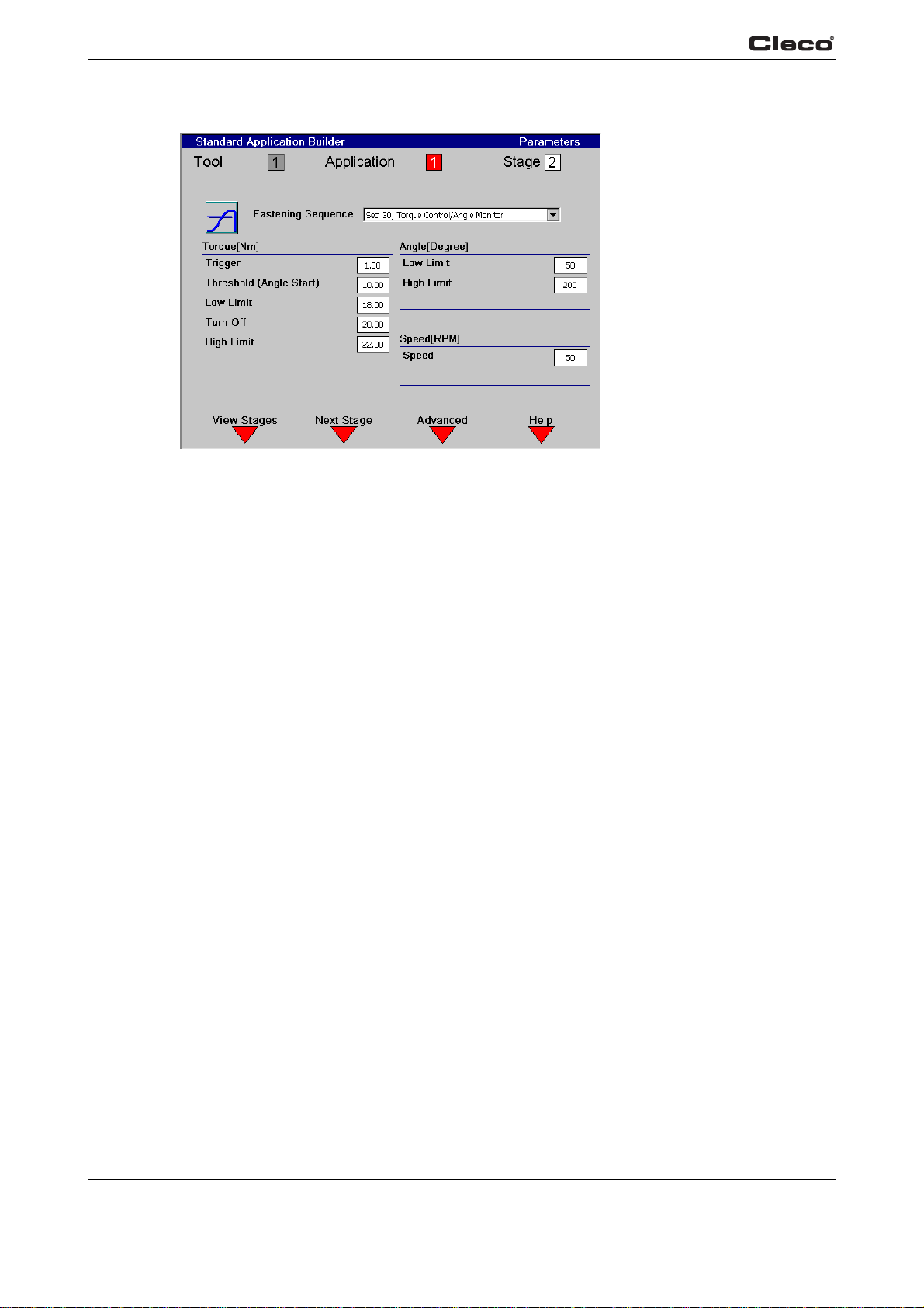
The parameters can be programmed for a certain tool, Application and Stage based on the
selected fastening strategy; then, only the parameters required for the Sequence are displayed.
The Next Stage
selected Sequence. It will then rollover to the first stage. In order to add a stage without a
selected Sequence, the user must highlight the stage field and enter a number from 1-6.
The following is a detailed description of each F
<F2> key will increment to the next stage until it reaches the last stage with a
astening Sequence and associated Parameters:
32 P1934E/EN 2009-04 en03c381.fm, 23.04.2009
Page 33

Programming
Sequence 11
High Speed Rundown
This tightening method is generally used as a fast pr
integrated into the nutrunner measures the torque during the tightening. The value is processed
by the control system. When the defined Turnoff Torque is reached the nutrunner is shut off.
Thereafter the peak torque is measured during a dwell time and is then processed as the tightening torque of the bolt in the control system. This valu
output to a printer or transmitted to other system components by data communication. When the
trigger torque is reached the torque curve is recorded and can be viewed and evaluated using
the oscilloscope function.
The following parameters are programmable from the Standard Application Builder:
• Fastening Sequence = 11
• Trigger Torque [Nm] = trigger torque, beginning of measurement for the graphic display
• Turnoff Torque (Nm) = turnoff torque for the pre-tightening stage.
• Speed = maximum speed of the nutrunner during the pre-tightening stage.
Parameter name Range Typical
Fastening strategy Sequence 11 High speed rundown
Trigger Torque [Nm] 0 to Tool Max 10% of Turnoff Torque
Turnoff Torque [Nm] Trigger to Tool Max As appropriate
Speed Stage 1 [RPM] 0 to Tool Max 80% of Tool Max
e-tightening stage. The torque transducer
e is displa
yed on the Run Screen and can be
3
en03c381.fm, 23.04.200 9 P1934E/EN 2009-04 33
Page 34

Programming
3
Sequence 16
Depth sensor, Angle Control with Angle and Torque Monitoring
This tightening method is generally used as a fast pr
depth sensor built in to the tool generates a signal at the preset insertion depth. This signal is
processed by the control system. At the start of the Stage, the system checks to see if the signal
is activated. If it is, the error TS is set for Depth Sensor error. When the programmed insertion
depth is reached, the nutrunner switches to angle control with angle and torque monitoring.
When the Turnoff angle is reached the nutrunner is shut off. Thereafter the peak torque is measured during a dwell time and is then processed as th
system. This value is displayed on the Run Screen and can be output to a printer or transmitted
to other system components by data communication. When the trigger torque is reached the
torque curve is recorded and can be viewed and evaluated using the oscilloscope function. The
depth signal is monitored for all further Stages. If the depth signal is deactivated as the rundown
proceeds, the error TS is set.
The following parameters are programmable from the Standard Application Builder:
• Sequence input value = 16
• Trigger Torque [Nm] = trigger torque, beginning of measurement for the graphic display
• Turnoff Angle [deg] = shut-off angle for the stage
• Angle High Limit [deg] = maximum angle, high limit for angle reached.
• Angle Low Limit [deg] = minimum angle, low limit for angle reached
• Torque High Limit [Nm] = maximum torque, high limit for torque reached an
• Speed = maximum speed of the nutrunner during the tightening stage.
e-tightening stage. During fastening, the
tightening torque of the bolt in the control
e
d sa
fety shut-off
Parameter name Range Typical
Fastening strategy Sequence 16 Depth sensor, angle control with
angle and torque monitoring
Trigger Torque [Nm] 0 to Tool Max 10% of End Torque
Torque High Limit [Nm] Low Limit to Tool Max. 130% of Final Torque
Angle Low Limit [Deg] 0 to 9999 90% of Turnoff Angle
Turnoff Angle [Deg] Low Limit to 9999 As appropriate
High Angle Limit Turnoff angle to 9999 110% of Turnoff Angle
Speed Stage [RPM] 0 to Tool Max 80% of Tool Max
34 P1934E/EN 2009-04 en03c381.fm, 23.04.2009
Page 35

Programming
Sequence 30
Torque Control with Torque and Angle Monitoring
This tightening sequence is generally preceded by a
integrated into the nutrunner measures the torque and the resolver measures the angle during
the tightening. The values are processed by the control system. When the threshold torque is
reached the angle count starts. When the defined Turnoff Torque is reached the nutrunner is shut
off. Thereafter the peak torque is measured during a dwell time and is then processed as the
tightening torque of the bolt together with the evaluation of the rundown in the control system.
This value is displayed on the Run Screen and can be output to a printer or transmitted to other
system components by data communication. When the trigger torque is reached the torque curve
is recorded and can be viewed and evaluated using the oscilloscope function.
The following parameters are programmable from the Standard Application Builder:
• Sequence input value = 30
• Trigger Torque (Nm) = trigger torque, beginning of measurement for the graphic display
• Threshold Torque (Nm) = threshold torque, beginning of angle counting
• Turnoff Torque (Nm) = shut-off torque for the stage.
• Torque High Limit (Nm) = maximum torque, high limit for torque reached.
• Torque Low Limit (Nm) = minimum torque, low limit for torque reached
• Angle High Limit (deg) = maximum angle, high limit
if this value is exceeded
• Angle Low Limit (deg) = minimum angle, low limit for angle reached
• Speed = maximum speed of the nutrunner during the tightening stage.
fast pre-tightening cycle. The transducer
angle reached. The nutrunner will stop
for
3
Parameter name Range Typical
Fastening strategy Sequence 30 Angle control / Torque Monitoring
Trigger Torque [Nm] 0 to Tool Max 10% of Turnoff Torque
Threshold Torque [Nm] 0 to Tool Max 50% of Turnoff Torque
Torque Low Limit [Nm] -tool maximum value* to tool
maximum va
Turnoff Torque [Nm] Low Limit to Tool Max. As appropriate
Torque High Limit [Nm] Turnoff to 9999 110% of Turnoff Torque
Angle Low Limit [Deg] 0 to 9999 70% of Final Angle
High Angle Limit Low Limit to 9999 130% of Final Angle
Speed [RPM] 0 to Tool Max 50
lue
90% of Turnoff Torque
en03c381.fm, 23.04.200 9 P1934E/EN 2009-04 35
Page 36

Programming
3
Sequence 50
Angle Controlled Tightening with Angle and Torque Monitoring
This tightening sequence is generally preceded by a
integrated into the nutrunner measures the torque and the resolver measures the angle during
the tightening. The values are processed by the control system. When the Turnoff angle is
reached the nutrunner is shut off. Thereafter the final angle and the peak torque are measured
during a dwell time, and these tightening values for the bolt are then processed together with the
evaluation of the rundown in the control system. These values are displayed on the Run Screen
and can be output to a printer or transmitted to other system components by data communication. When the trigger torque is reached the torque curve is recorded and can be viewed and
aluated using
ev
The following parameters are programmable from the Standard Application Builder:
• Sequence input value = 50
• Trigger Torque (Nm) = trigger torque, beginning of measurement for the graphic display
• Threshold Torque (Nm) = threshold torque, beginning of angle counting
• Turnoff Angle (deg) = shut-off angle for the stage
• Angle High Limit (deg) = maximum angle, high limit for angle reached.
• Angle Low Limit (deg) = minimum angle, low limit for angle reached
• Torque High Limit (Nm) = maximum torque, high limit for torque reached and safety shut-off
• Torque Low Limit (Nm) = minimum torque, low limit for torque reached
• Speed = maximum speed of the nutrunner during the tightening stage.
the oscilloscope function.
fast pre-tightening cycle. The transducer
Parameter name Range Typical
Fastening strategy Sequence 50 Angle Control/Torque Monitoring
Trigger Torque [Nm] 0 to Tool Max 10% of Turnoff Torque
Threshold Torque [Nm] 0 to Tool Max As appropriate
Torque Low Limit [Nm] -tool maximum value* to tool
maximum va
Torque High Limit [Nm] Low Limit to Tool Max. 130% of Final Torque
Angle Low Limit [Deg] 0 to 9999 90% of Turnoff Angle
Turnoff Angle [Deg] Low Limit to 9999 As appropriate
High Angle Limit Turnoff angle to 9999 110% of Turnoff Angle
Speed Stage [RPM] 0 to Tool Max 50
lue
70% of Final Torque
36 P1934E/EN 2009-04 en03c381.fm, 23.04.2009
Page 37

Programming
Sequence 41
Angle Controlled Back-off with Angle Monitoring
This fastening sequence is generally used to loosen a bo
lt a specified number of degrees. The
resolver integrated into the nutrunner measures the angle during the backoff. The value is processed by the control system. When the Turnoff angle is reached the nutrunner is shut off.
eafter the final angle is measured during a dwell time and is then processed as the back-off
Ther
angle of the bolt together with the evaluation of the backoff in the control system. This value is
displayed on the Run Screen and can be output to a printer or transmitted to other system
components by data communication. In this stage the oscilloscope function is not supported.
The following parameters are programmable from the Standard Application Builder:
• Sequence input value = 41
• Turnoff Angle (deg) = shut-off angle, back-off angle
• Angle High Limit (deg) = maximum angle, high limit for angle reached.
• Angle Low Limit (deg) = minimum angle, low limit for angle reached
• Speed = maximum speed of the nutrunner during the back-off stage.
Parameter name Range Typical
Fastening strategy Sequence 41 Angle Control Reverse
Angle Low Limit [Deg] 0 to 9999 90% of Turnoff Angle
Turnoff Angle [Deg] Low Limit to 9999 As appropriate
High Angle Limit Turnoff angle to 9999 110% of Turnoff Torque
Speed Stage [RPM] 0 to Tool Max 80% of Tool Max
3
The following parameters are programmable from the Standard Application Builder:
• Speed [rpm] = maximum speed of the nutrunner during the backoff stage.
Parameter name Range Default
Speed Stage [RPM] 0 to Tool Max 500 or 30% of tool Max value for
tube wrenches
The backoff parameters that are not displayed are set to values as in the table below.
Parameter name Sequence 41
Start delay time [mS] 0
Start spike time [mS] 0
Max. fastening time [ms] 10000
End delay time [mS] 30
Torque Filter Factor 1
Torque target ---
High Torque Limit ---
Low Angle Limit 0
Angle Target 9999
High Angle Limit 9999
For a tube wrench, the maximum speed for backoff is 30% of the maximum tool speed. It is not
possible to enter a higher value.
paramete.txtE
en03c381.fm, 23.04.200 9 P1934E/EN 2009-04 37
Page 38
Programming
3
3.3.5 Standard Application Builder / Advanced Parameters
Fig. 3-9: Advanced parameters
c00283en.bmp
advparam.txtS
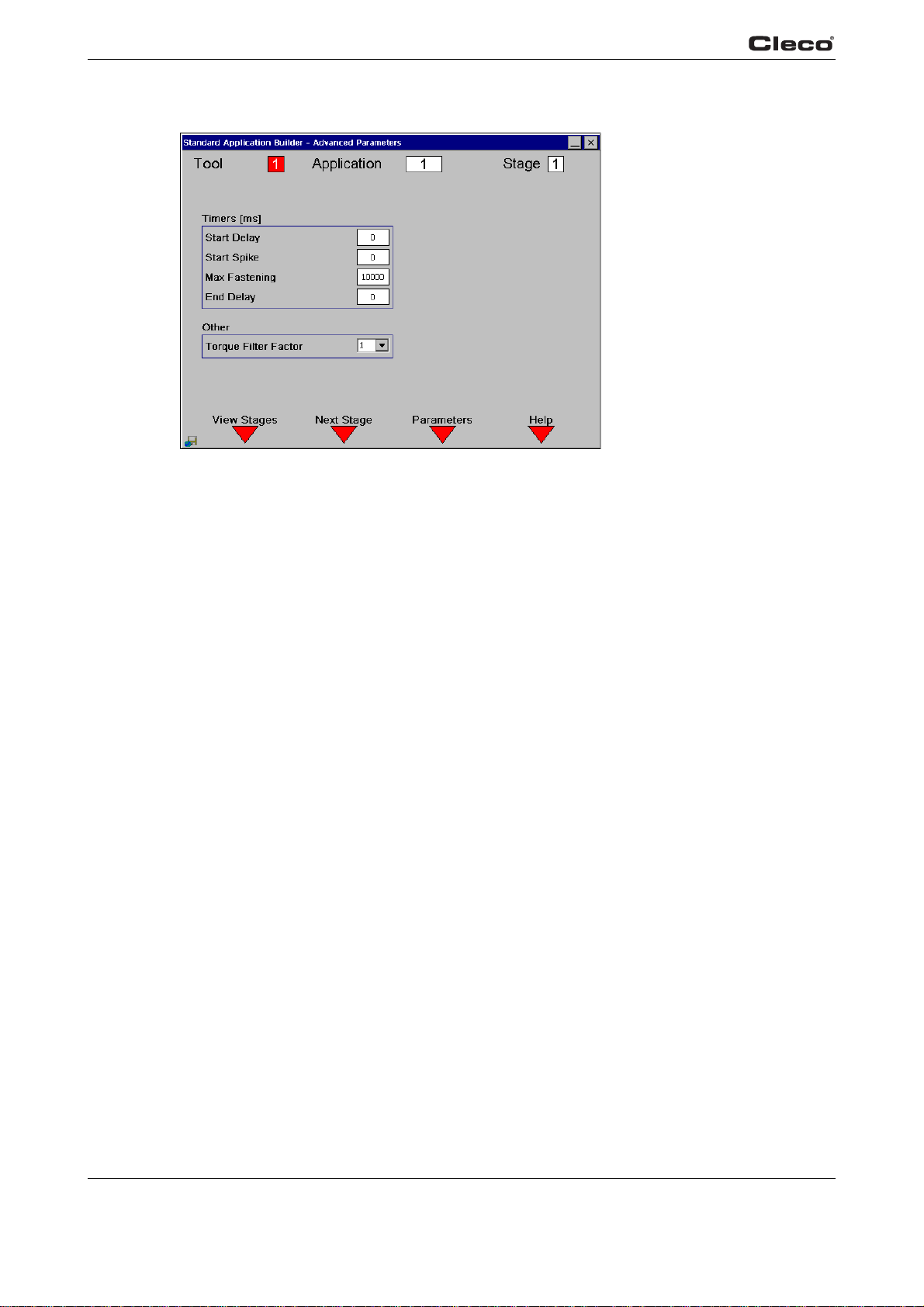
The user can enter the Advanced Parameters using the Advanced <F3> Softkey from the
Parameter screen. These parameters are identical regardless of the selected Fastening
Sequence.
The Next Stage
selected Sequence. It will then rollover to the first stage. In order to add a stage without a
selected Sequence, the user must highlight the stage field and enter a number from 1-6.
Timers
Start delay time [mS] = Time delay before the start of the stage.
Start spike time [m] = Time delay for the control system to start
Max Fastening [ms] = Maximum time for the rundown in this Stage.
End delay time [ms] = Time delay from the tool turnoff until the torque measurement ends.
Others
Torque Filter Factor = for calculating torque mean value.
<F2> key will increment to the next stage until it reaches the last stage with a
measuring torque after the stage
starts.
38 P1934E/EN 2009-04 en03c381.fm, 23.04.2009
Page 39
Programming
3
Advanced parameter
Default Range of values
display
Start delay time [mS] 0 0 - 60000
Start spike time [mS] 0 0 - 999
Max Fastening [ms] 10000 1 - 60000
End delay time [mS] 30 0 - 999
Torque Filter Factor 1 1, 2, 4, 8, 16, 32
advparam.txtE
3.4 Advanced
3.4.1 Advanced Application Builder / Application Matrix
Fig. 3-10: Application Matrix
appmatri.txtS
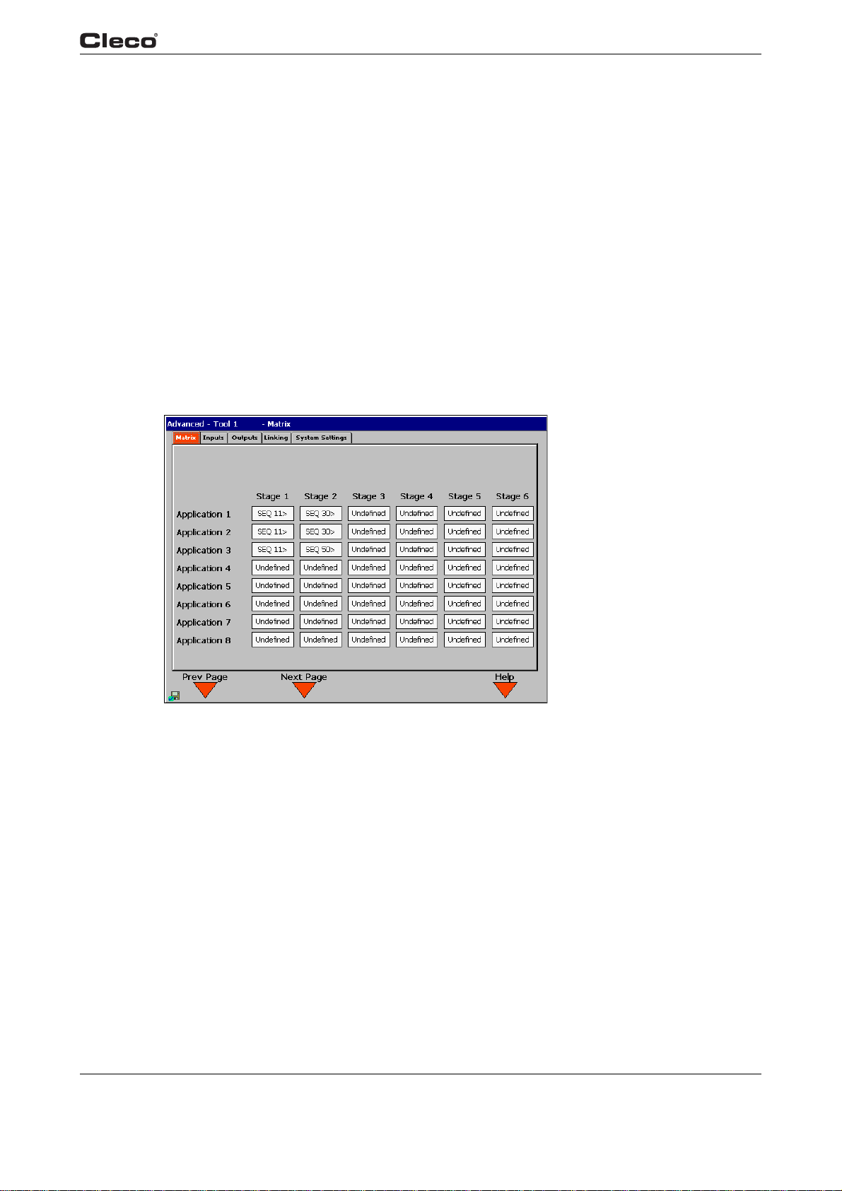
The Application Matrix is a display matrix of 255 Applications vs. 6 Stages showing the selected
Sequence number for each stage. It gives the user an overview of controller programming in a
single screen. The arrow after each Sequence number for a Stage indicates the direction of
rotation ( > clockwise; < counterclockwise).
appmatri.txtE
en03c381.fm, 23.04.200 9 P1934E/EN 2009-04 39
c00284en.bmp
Page 40
Programming
3
3.4.2 Advanced Application Builder / Inputs
Fig. 3-11: Inputs
To ol
In holder
Inputs
App selection D0..D7
Reset linking
NOK interlock
Tool Enable, External Tool
Enable
– only for TMEB-200 / TMEC
Tool
Out of
holder
Offline
Fastening
To ol
In holder
Tool Out
of holder
c00285en.bmp
Outputs
Tool online
Tool synchronized
Step complete
Linking OK
Linking NOK
Mirroring App D0..D7
Fig. 3-12: Timer sequence
inputs.txtS
40 P1934E/EN 2009-04 en03c381.fm, 23.04.2009
b00585.wmf
Page 41

Programming
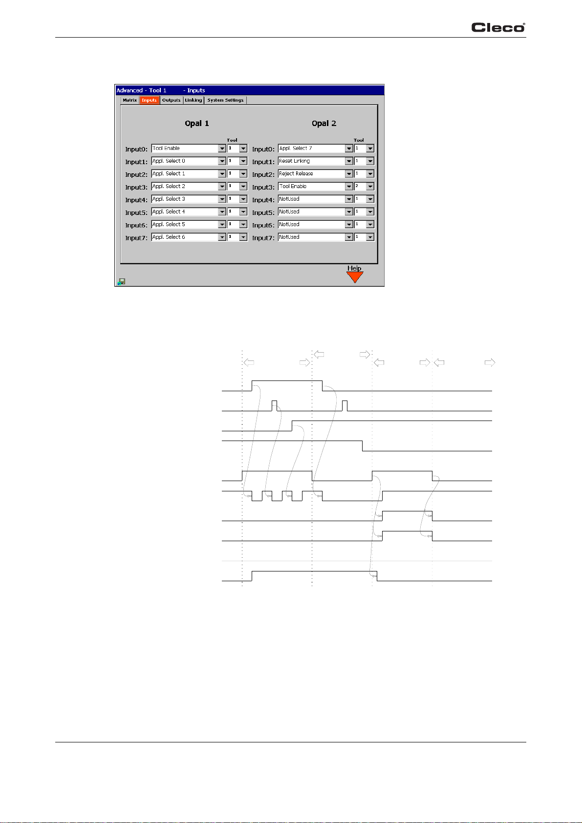
There are two groups of eight optically decoupled +24 V inputs available at the Phoenix input
connectors. They are defined as follows:
PIN 1 +24 VDC
PIN 2 Input 0
PIN 3 Input 1
PIN 4 Input 2
PIN 5 Input 3
PIN 6 Input 4
PIN 7 Input 5
Pin 8 Input 6
PIN 9 Input 7
PIN 10 Input Common
Pin 11 Signal Ground
Pin 12 Spare
3
A +24 V input can be assigned to a signal from a specific too
pin 4 from Opal 1 can be used as a Tool Enable from tool 3 or Tool Enable for all tools.
When Tool Enable for
the system.
Not used Not used
External Tool enable When activated, the tool can be used in conjunction with Tool
Application selection 0 Application selection 0-7 is used to select from Applications
Application selection 1
Application selection 2
Application selection 3
Application selection 4
Application selection 5
Application selection 6
Application selection 7
Reset step When activated, the step (batch count
NOK interlock Used when the NOK interlock is acti
all tools is used, the chosen input is passed as Tool E nabl e to all tools in
art.
St
1-255
with the aid of a binary counter 0-254, with application
selection 0 being the bit with the lowest priority. This function
overwrites Application changes made with the keyboard. When
the step is activated, the tightening group with these inputs is
selected.
one.
the enable method is External Tool enable. If the tool is disabled
because the number of NOK rundowns has been reached, this
input is activated again after changeover.
l
or to all tools. For example, input
e
r) is reset to set position
vated by system settings and
All inputs are active high. They are referenced to an isolated
the internal +24 V (pin 1) to activate these inputs, you must connect Input Common (pin 10) and
GND (pin 11).
inputs.txtE
en03c381.fm, 23.04.200 9 P1934E/EN 2009-04 41
Input Common (pin 10). When using
Page 42
Programming
3
3.4.3 Advanced Application Builder / Outputs – only for TMEB-200 / TMEC
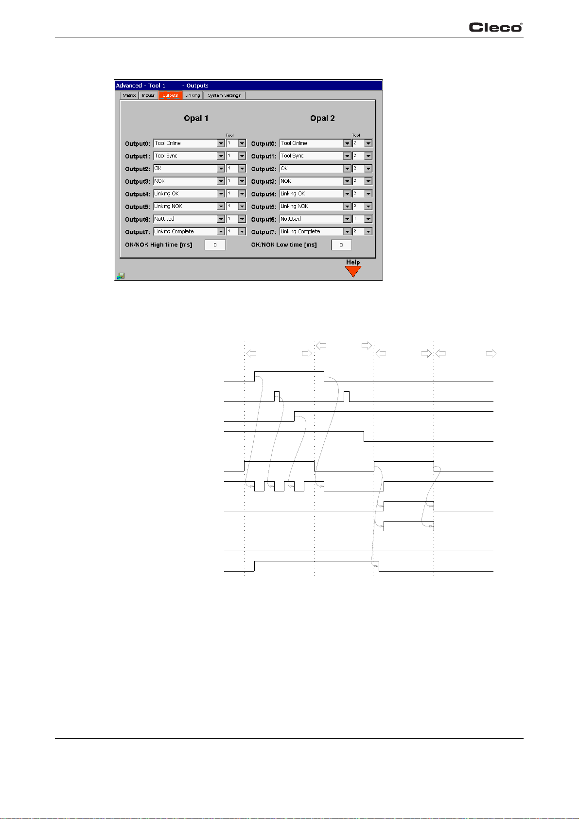
Fig. 3-13: Outputs
c00286en.bmp
outputs.txtS
Inputs
App selection D0..D7
Reset linking
NOK interlock
Tool Enable, External Tool
Enable
Outputs
Tool online
Tool synchronized
Step complete
Linking OK
Linking NOK
Mirroring App D0..D7
Fig. 3-14: Timer sequence
Tool
In holder
To ol
Out of
holder
Offline
Fastening
Tool
In holder
Tool Ou t
of holder
b00585.wmf
42 P1934E/EN 2009-04 en03c381.fm, 23.04.2009
Page 43

Programming
There are two groups of eight optically decoupled +24 V outputs available at the Phoenix output
connectors. They are defined as follows:
PIN 1 +24 VDC
PIN 2 Output Common
PIN 3 Output 0
PIN 4 Output 1
PIN 5 Output 2
PIN 6 Output 3
PIN 7 Output 4
Pin 8 Output 5
PIN 9 Output 6
PIN 10 Output 7
Pin 11 Signal Ground
Pin 12 Spare
3
A +24 V output can be assigned to a signal from a specific
Opal 2 can be used as Step complete from tool 6:
Not used Not used
OK Active if Torque / Angle / Yield are within programmed limits
NOK Active if Torque / Angle / Yield are outside limits or some other
er
ro
r has occurred
Linking finished Active when execution of all set positions / steps for the
selected tighte
Tool online Active as long as an assigned tool in the tool holder is
communicating
Tool synchronized Active when all data have been reconciled after successful
communication
Linking OK Active if all set positions / steps for the tightening group were
OK
Linking NOK Active if one or more set positions /
group were NOK
Mirroring App D0 Mirroring App D0-7 is used to designate the currently selected
Mirroring App D1
Mirroring App D2
Mirroring App D3
Mirroring App D4
Mirroring App D5
Mirroring App D6
Mirroring App D7
application
mirroring App D0 being the bit with the lowest priority.
ning group are complete
with the system
between TMEB and tool
s 1-255 with the aid of a binary counter of 0-254,
too
l. For example, output pin 5 from
s for the tightening
step
ATTENTION!
en03c381.fm, 23.04.200 9 P1934E/EN 2009-04 43
If the tool is not connected, the outputs are reset. The signal TOOL SYNCHRONIZED and
MIRRORING App D0-D7 is an exception. Outputs are updated after rundown data are
ived
rece
Page 44
Programming
3
All relay outputs are active high. One side of all of the relay contacts is tied to a common point
called Output Common (pin 2). When using the internal +24 V (pin 1) as a source for these outputs, you must connect Output Common (pin 2) and +24 V
enced to GND (pin 11). For hardware pin location please see 2.2.7 Input / output connectors,
page 18.
OK/NOK High time [ms] Specifies the amount of time an output signal stays in "high"
state.
Once the time is up, output signal is changed back to
"low" state. Acceptable range is 0 - 10000 milliseconds. This
behavior applies only for Cycle OK, Cycle NOK, Torque Low,
Torque High, Angle Low, Angle High, Torque OK, Angle OK,
Cycle Complete outputs. If 0 is entered, this function is disabled. (Fig. 3-13:Outputs, Fig. 3-14:Timer sequence)
OK/NOK Low time [ms] Specifies the amount of time an output signal stays in "low"
ate betwee
st
10000 milliseconds. This behavior applies only for Cycle OK,
Cycle NOK, Torque Low, Torque High, Angle Low, Angle
High, Torque OK, Angle OK, Cycle Complete outputs. If 0 is
entered, this function is disabled.
n two rundown results. Acceptable range is 0 -
(pin 1). The outputs will then be refer-
outputs.txtE
3.4.4 Advanced / Linking
Fig. 3-15: Linking
linking.txtS
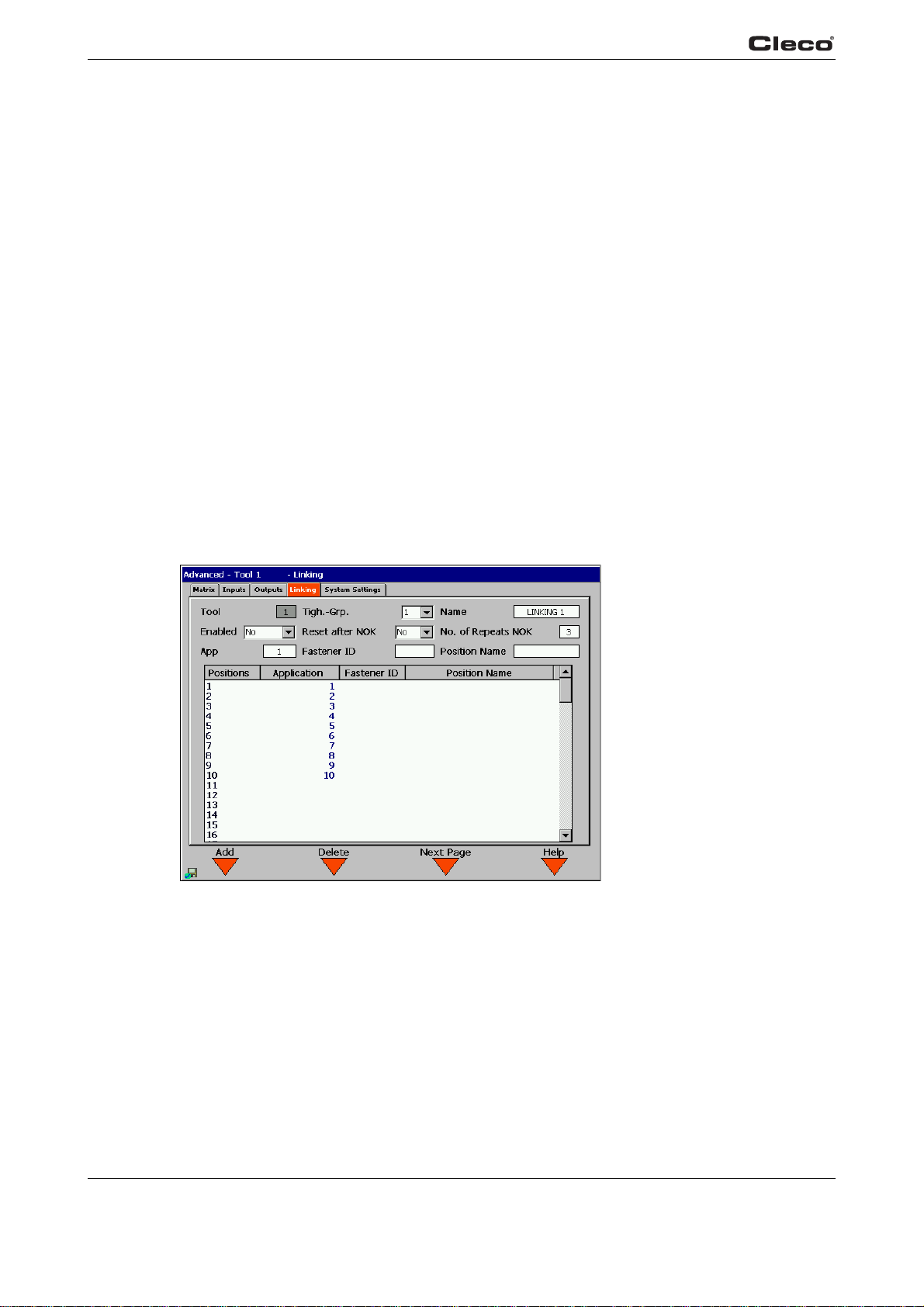
Linking allows automatic application changes for a programmed number of positions (rundowns).
You can program up to 96 positions. Each application is run when the start switch on the tool is
activated in the order specified by its position. Upon completion of the cycle, the application will
then automatically change to the next position. This automatic change is available for eight
groups, termed tightening groups. The corresponding tightening groups can be selected via the
external inputs (0-2), or via the Run Screen. This feature can also be used for Batch Counting by
entering the same application in the desired number of positions.
c00315en.bmp
44 P1934E/EN 2009-04 en03c381.fm, 23.04.2009
Page 45
To setup a linking strategy, a Tightening Group 1-8 should be selected and given a name. This
will designate which linking strategy is being used. The user can also program if the linking strategy should reset to position 1 after an NOK or set the number of times a fastener can be retightened after an NOK before advancing to the next po
To allocate the Application to the corresponding step, enter a corresponding number (1-255) in
the Ap
plication field. If necessary, you can also assign a fastening location number as well as a
designation for each step. Pressing Add <F1> adds the selected Application as the last step.
Pressing Delete <F2> removes the last step. Once Linking is enabled, the controller will automatically run from position 1 to the last programmed p
remote start input will have to be toggled between positions. The Tightening Group and Position
will also be displayed on the Run Screen.
The following inputs and outputs will also be active
OK, Linking NOK, Linking complete.
Inputs: Reset Linking. Please refer
these signals.
linking.txtE
3.4.5 Advanced / System Settings
Programming
sitio
n. Up to three repetitions are permitted.
o
sition. Note that the tool start switch or
when Linking is enabled: Outputs: Linking
to the Inputs and Outputs section for more information on
3
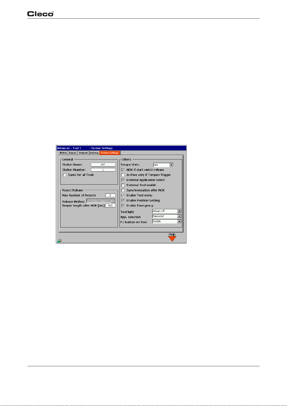
Fig. 3-16: System Settings
sysset.txtS
en03c381.fm, 23.04.200 9 P1934E/EN 2009-04 45
From the System Settings Screen the user can configure parameters pertaining to the system.
General
Allows the user to assign an identifying name and num
will be used when sending and printing data.
Station Name (10 characters - alphanumeric)
Station Number (10 characters - alphanumeric)
ber to the TME controller. This information
c00313en.bmp
Page 46

Programming
3
Same for all tools If this check box is marked, the station name and station num-
ber last entered are automatically synchronized and used for
ll too
ls. If this check box is not marked, the station name and
a
the station number can be programmed separately for each
tool.
Use of this check box also impacts the serial communication
r
otocols Standard, Standard2 and 3964R. If Identical for all
p
tools has not been selected, the transmitted 2-digit ASCII tool
number from the Station number field is used. If Identical for
all tools has been selected, the transmitted 2-digit ASCII tool
number is hard-coded as 01 or 02, depending on the tool from
which the rundown data originate.
NOK interlock
Max Number of Rejects Allows the user to enter the maximum num
will be permitted before a release signal is required. If 0 is
entered, the function is disabled.
Release Method Release on Backoff
allows the user to set running the tool in reverse as a release
signal.
External Input
ws the user to set a low-high pulse to NOK Release as a
Allo
e
lease signal.
r
Signal sound after NOK
[0 to 9999 milliseconds]
Defines whether after an acoustic signal is activated for the
enter
ed time after an NOK rundown. If 0 is entered, this func-
tion is disabled.
ber of rejects that
46 P1934E/EN 2009-04 en03c381.fm, 23.04.2009
Page 47

Programming
Others
System Torque Units You can select the system torque units that the TME station
contro
ller uses. The following are available for selection: Nm,
FtLbs (feetpound), InLbs (inchpound) and KgCm. If the unit
changes, all torque values are immediately converted to the
new unit.
NOK if start switch release Causes NOK status after a rundown with premature Cancel
use start enable is withdrawn. This is always the case if
beca
the rundown did not terminate as programmed, i.e. the tool
failed to reach the shut-off or upper limit value for torque or
angle or reached the Maximum Fastening Time. In this case,
a NOK result is generated.
Note: If
e
within the tolerance range; reaching of the shutoff criterion is
not required.
this parameter is not activated, then a rundown is
valuated as OK if the last Stage is reached and the values lie
3
Archive only if
rque > Trigger
To
External Application Select – Only for TMEB-200 / TMEC:
External Tool enable – Only for TMEB-200 / TMEC:
Synchronization after NOK Specifies that the tool is disabled after a NOK rundown until
Enable tool menu Enables the tool menu. If this optio
Enable Set Position Enables the Set po
Enable Emergency Strategy The emergency strategy can be enabled on the tool under
Allows the user to specify that only rundowns for which the
torque is larger than the Trigger torque of the last fastening
stage should be saved in the Chrono History.
Specifies that there must be an external signal at input 0..7 to
select the a
controller defaults to Application 1.
Specifies that there must be an external signal at input 6 for
the se
da
ta has been synchronized between TMEB and tool
functions are enabled on the tool. The functions Set position
and Emergency strategy are not affected by this.
can be used to change the current link position. If the link
position is changed manually, the linking result is always evaluated as NOK.
Administration/Emerge
enabled if communication with the TMEB-200 / TMEB-COM /
TMEC is interrupted. I
ters used are applied to further rundowns. Once communication is restored, the Emergency st
disabled.
For steps, the last fastening pa
ing parameters of the last step executed; when there are no
steps, the p
pplication. In the absence of a signal, the TME
quence to start.
n is selected, the menu
sition submenu on the tool. This submenu
ncy strategy. It can be
n this case, the last fastening parame-
rategy
is automatically
rameters used are the fasten-
arameters of the last executed rundown are used
en03c381.fm, 23.04.200 9 P1934E/EN 2009-04 47
Page 48
Programming
3
App. selection Gives the user the ability to select the T
Tool light Defines the activation of the LED lighting on the tool.
F1 on tool Defines the function of the left function key on the tool.
sysset.txtE
3.5 RUN Screen
ightening Group/Appli-
cation in the Run Screen.
• Allowed
Changing the Tightening Group/Application with no
ssa
ge is permitted.
me
• Warning
A warning is output after the Tightening Group/Application
ang
is ch
• Password
A password is required to change the active Tightening
r
g
•Locked
Changing the Tightening Group/Application is disallowed.
ed.
oup/Application.
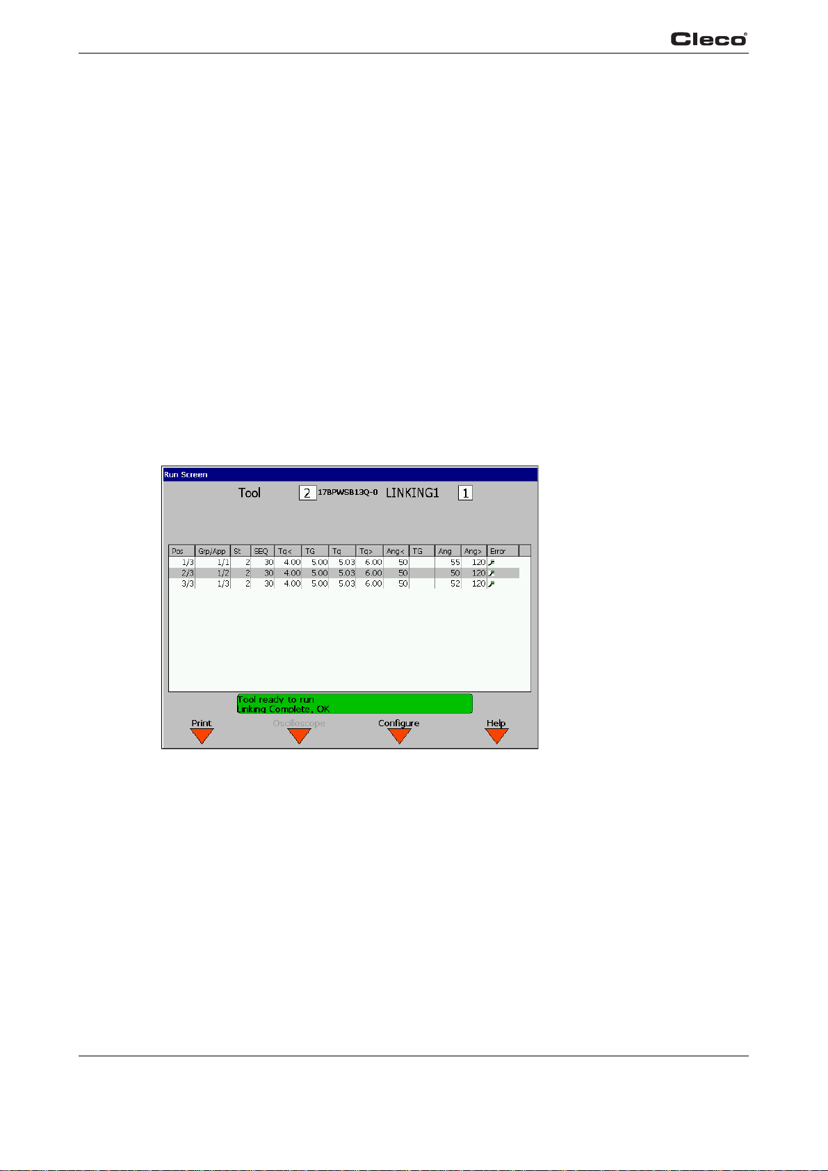
Fig. 3-17: RUN Screen
runscrn.txtS
The Run Screen displays currently received rundown data in tabular form.
The table contains the following data:
Pos Displays the step and the total step count
Grp/App Tightening Group for steps or application
St Last step executed
SEQ Fastening strategy employed
48 P1934E/EN 2009-04 en03c381.fm, 23.04.2009
c00289en.bmp
Page 49

Tq< Low Torque
TG Peak torque
Tg Torque reached
Tq> MaxTorque
Ang< Minimum tightening angle
TG Shut-off angle
Ang Calculated shut-off angle
ANG> Maximum tightening angle
Error A fault has occurred
The following abbreviations are used to designate the fault that has occurred
TMAX Maximum fastening time exceeded
TS Depth sensor signal was active at start or was disabled in
the
urse of the fastening sequence
co
Tq< Torque too low
Programming
3
Tq> Torque too high
Ang< Angle Low
ANG> Angle High
IIT IIT fault; the requested motor output is
IP Current overload in output section
CAL Torque encoder calibration fault
ENC Angle encoder fault
OFF Torque encoder offset fault
RC Rundown terminated by disabled start signal
NOK Result is not okay
The currently selected tool number and model number are displayed.
The desired Application (1-255), Tightening Group (1
selectable using the keypad.
Note: The Application Number or Tightening Group displayed in the one currently
e
lected. The tabular values for Application Number or Tightening Group refer to the
s
displayed result and can therefore vary.
high
too
-8
, if enabled), and Part ID (if enabled) are
When enabled, the Part ID and Part ID Status boxes are displayed below the Tool and Application. When allowed, the Part ID edit box may be used
pad or an attached keyboard.
Note: when manually entering a Part ID, the <ENTER> key must be pressed to validate the
nt
ry. During manual entry, the <ESC> key may be pressed to return to the previous
e
Part ID and state of validity.
en03c381.fm, 23.04.200 9 P1934E/EN 2009-04 49
to manually enter a Part ID using the key-
Page 50

Programming
3
The Part ID Status box contains three indicators:
1. Valid: Indicates whether or not the tool ID is valid,
tool is enabled:
- "Part ID: Accepted“ (green LED): Part
- “ID invalid: Tool disabled“ (red LED): When configured in INTERLOCK mode, an invalid
Part ID causes the t
tool.
- “ID invalid: Tool enabled“ (yellow LED): When
tool may be run without entering a valid Part ID.
2. Function: Indicates the status of
- “Function: not configured” (clear LED): Part ID “Data Function” is configured to "None".
- “Function: None” (yellow LED): Part ID “Con
invalid or does not match any Configure Data entries.
- “Function: XYZ” (green LED): Part ID “Configure Da
has engaged function XYZ (see Communications - Part ID help screen for function definitions).
3. Input status: Indicates whether or not a ne
- “Accepting Part ID input” (green LED
- “Not Accepting Part ID input” (red LED): A new Part ID may not be entered.
- A new Part ID can not be entered when the tool is not connected or is switched off
- "NEW ENTRY IGNORED!" (red LED): This status is d
while “Not Accepting Part ID input” is true.
ool to be disabled. A new, valid Part ID must be entered to enable the
ID is valid. The tool is always enabled.
Part ID Data Function:
w Par
): A new Part ID may be entered.
and when not valid, whether or not the
configured without INTERLOCK mode, the
figure Data” is enabled, but the Part ID is
ta” is enabled, and the current Part ID
t ID can be entered.
isplayed if a new Part ID is entered
runscrn.txtE
Below the Torque and Angle display is the “Status” window. This window displays various messages related to the tool, rundown status, or errors.
The <F1> “Print” Softkey causes any rundown data that has not previously been printed to be
nt t
o the parallel port printer interface. If the Part ID is configured to “Print Interlock”, the Part ID
se
is invalidated, and the tool is disabled.
The <F2> “Oscilloscope” Softkey displays
Angle curves. It is automatically updated after each cycle. Result line must be highlighted.
The Run Screen can be configured for various options. To make these options available, press
the Conf
allows you to adapt the Run Screen and Oscilloscope transmission. For Oscilloscope transmission, you can choose between NOK result
only in order to minimize data transmission time.
The 2 tool display allows display of data from multiple tools (up to 10 maximum.) The t
options are Man. changeover and Auto changeover. See Run Screen / Configure. Manual
select displays data from a single tool (1 to 10 maximum.) The user can have the Run Screen
switch automatically to the tool with the most recent result reports by selecting the Auto
changeover field.
igure <F3> softkey. See Run Screen / Configure. Run Screen / Configure
the Oscilloscope function for evaluating Torque and
s
only and All. Set NOK Oscilloscope transmission
ool display
50 P1934E/EN 2009-04 en03c381.fm, 23.04.2009
Page 51
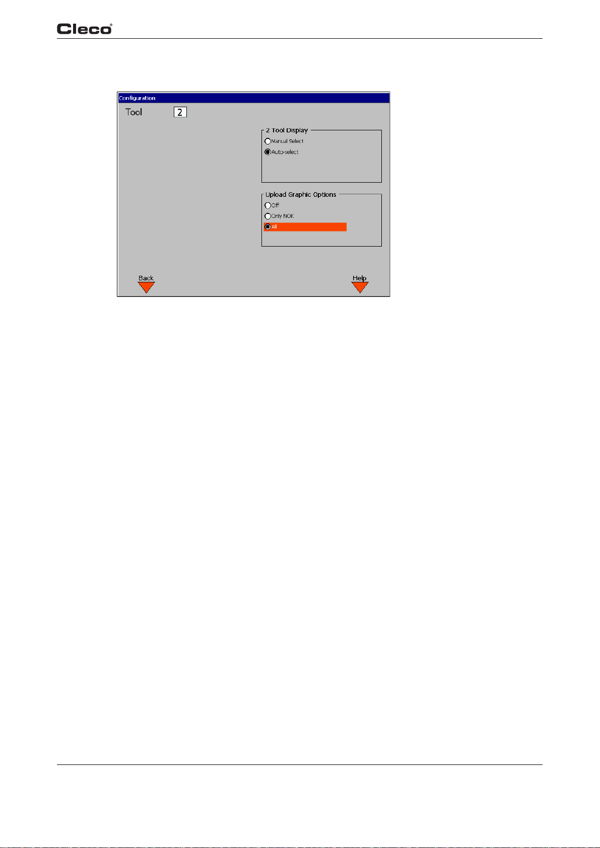
Programming
3
3.5.1
runcfg.txtS
runcfg.txtE
Run Screen / Configuration
c00364en.bmp
Fig. 3-18: Configure Data
Run Screen / Configuration allows you to adapt the Run Screen and Oscilloscope transmission.
For Oscilloscope transmission, you can choose between Off, Only NOK and All. Only use Off or
Only NOK to reduce the time for the data transmission.
en03c381.fm, 23.04.200 9 P1934E/EN 2009-04 51
Page 52
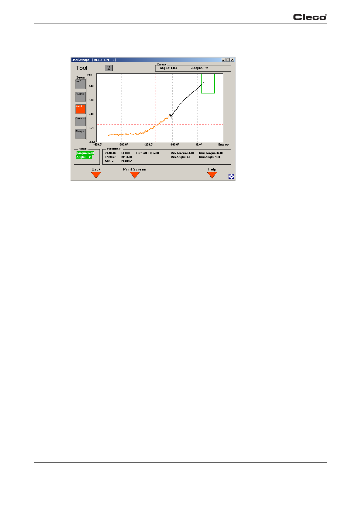
Programming
3
3.6 Oscilloscope
c00290en.bmp
oscope.txtS
Fig. 3-19: Oscilloscope Operation
The Oscilloscope function displays a Torque vs. angle curve after each complete rundown in the
tightening direction. The curve is colored in alternating red and black lines to indicate the different
stages. A green frame is also displayed surrounding the torque and angle limits. There is a data
point for each degree of angle rotation.
Archive
The function Archive Last displays the last r
each rundown. Alternatively, the last three graphs can be displayed without automatic update.
Note: If NOK o
Transmission, no graph is displayed for an OK result.
Zoom
Using the Zoom indicators on the left side of the display, you can enlarge a specific area of the
torq
ue trace. Using the up/down arrow keys, highlight the Left zoom button. Using the left/right
arrow keys, set the orange vertical line to the left extent of the desired zoom window. Then,
select Right and move the yellow line to the right border of the desired zoom window. Once you
have set the window borders, press the <Enter> key; the oscilloscope section appears enlarged.
Select the Zoom button 1:1 and press the <Enter> key to restore the original display without
magnification.
Cursor
The cursor (red cross-hatch) can be moved along the torque trace using the left and right arrow
T
keys.
play.
he actual torque and angle values of the cursor position are shown at the top of the dis-
nly is selected under Run Screen/Configuration Torque Graph
undown. The display is updated automatically after
Stage
The Stage softkey allows you to select the corresponding stage by input of a stage number
(0 to 6). If you enter 0 the
52 P1934E/EN 2009-04 en03c381.fm, 23.04.2009
entire rundown is shown.
Page 53
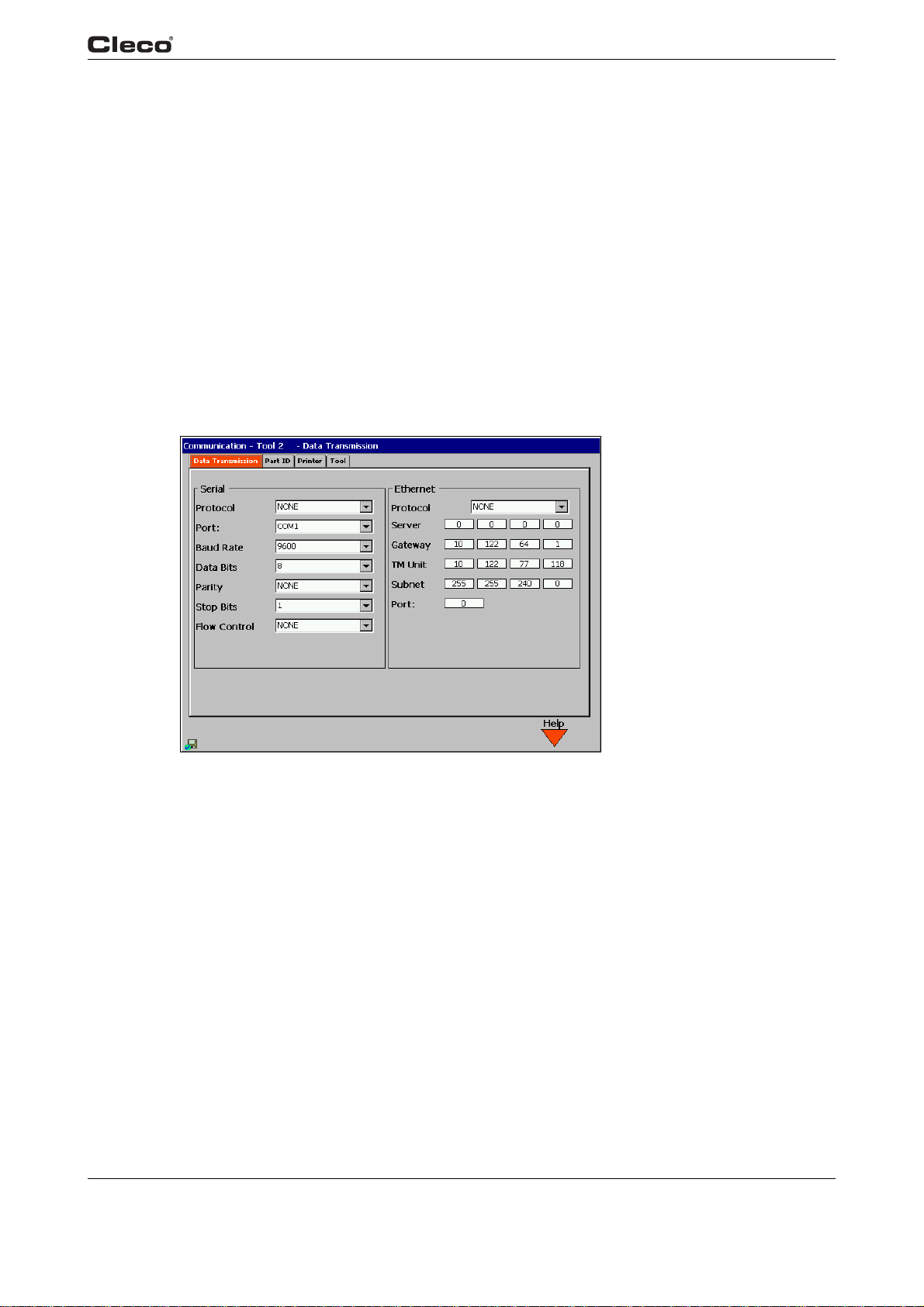
Rundown Indicator
At the bottom left of the display is the rundown indicato
displayed on either a green (OK) background or red (NOK) background.
Parameter
At the bottom of the display is a summary of the p
oscope.txtE
The Print Screen
Note: In the display for Sequence 41, backoff is shown as negative torque in the graph; in
l the other displays, however, it is input and displayed as positive torque.
al
softkey <F2> lets you print a hardcopy.
3.7 Communications
3.7.1 Communications / Ethernet
Programming
3
r. The final torque and angle values are
arameter settings for the rundown.
Fig. 3-20: Data Transmission
commdata.txtS
From the Data Transmission Screen the Serial and Ethernet connections can be configured.
en03c381.fm, 23.04.200 9 P1934E/EN 2009-04 53
c00404en.bmp
Page 54

Programming
3
Serial
Protocol None, Standard, Standard2, PFCS, CT01 39
64R, Appolo 3.1
Port COM 1, COM 2
Baud rate 2400, 4800, 9600, 14400, 19200, 38400, 57600, 115200
Data bits 4, 5, 6, 7, 8
Parity None, Odd, Even, Mark, Space
Stop bits 1, 1.5, 2
Flow Control None, Hardware, Xon/Xoff
The Pr
otocol field
allows the user to select from among various protocols. If Standard is selected,
then the serial data transmission is sent after each cycle to the programmed COM port. If
Appolo 3.1 is selected, then once linking is OK, a special pr
otocol for a label printer is sent to the
programmed COM port. The Basic settings are Port, Baud rate, Data bits, Stop bits, Parity, and
Protocol.
The communication protocols Standard, Standard2 and
CT01 3964R serial can be configured as
individual serial port (COM1 or COM2) for each tool or in such a way that a single serial port is
shared by up to 10 tools. The"Tool Number" transmitted is a 2-digit ASCII field, programmed
under Advanced/System settings/Station number. If the option Advanced/System
settings/Identical for all tools is selected, the tool number field is hard-coded as
01, 02 up to the number of tools.
The following table details the transmission data for Standard:
Start End Length or Value Description
1 1 42 hex B
2 3 2 Digit ASCII Tool Number
4 5 2 Digit ASCII Application (1-99)
6 17 12 Char ASCII Date and Time (YYMMDDHHMMSS)
18 24 7 Digit ASCII Peak Torque
25 31 7 Digit ASCII Low Torque Limit
32 38 7 Digit ASCII High Torque Limit
39 39 1 Char ASCII Status Torque status Flag
L = low
A = accept
H = high
40 46 7 Digit ASCII Final Angle
47 53 7 Digit ASCII Low Angle Limit
54 60 7 Digit ASCII High Angle Limit
61 61 1 Char ASCII Status Angle status Flag
L = low
A = accept
H = high
62 62 1 Char ASCII Status Overall status Flag
A = accept
R = reject
54 P1934E/EN 2009-04 en03c381.fm, 23.04.2009
Page 55

Programming
Start End Length or Value Description
63 64 2 Digit ASCII Step/Position
(only for linking)
65 66 2 Digit ASCII Number of linked positions
(Only for Linking)
67 67 0D hex CR (carriage return)
68 68 0A hex LF (line feed)
The following table details the transmission data settings for the Standard2 protocol:
Start End Length or Value Description
1 1 42 hex B
2 3 2 Digit ASCII Tool Number
4 6 3 Digit ASCII Application (1-255)
7 18 12 Char ASCII Date and Time (YYMMDDHHMMSS)
19 25 7 Digit ASCII Peak Torque
26 32 7 Digit ASCII Low Torque Limit
3
33 39 7 Digit ASCII High Torque Limit
40 40 1 Char ASCII Status Torque status Flag
L = low
A = accept
H = high
41 47 7 Digit ASCII Final Angle
48 54 7 Digit ASCII Low Angle Limit
55 61 7 Digit ASCII High Angle Limit
62 62 1 Char ASCII Status Angle status Flag
L = low
A = accept
H = high
63 63 1 Char ASCII Status Overall status Flag
A = accept
R = reject
64 65 2 Digit ASCII Step/Position
(only for linking)
66 67 2 Digit ASCII Number of linked positions
(Only for Linking)
68 68 0D hex CR (carriage return)
69 69 0A hex LF (line feed)
If Part ID is ENABLED, then a 25 character ASCII part ID is transmitted prior to CR/LF.
en03c381.fm, 23.04.200 9 P1934E/EN 2009-04 55
Page 56

Programming
3
Ethernet
Protocol None, Standard, Standard Plus, PFCS
The Ethernet settings include:
• Server IP Address
• Gateway
•TME
• Subnet Mask
•Port
See your network administrator for proper settings. For
Technical Service Representative in Customer Satisfaction.
If the S
messages containing a Station number the station number for Tool 1 is used. For Rundown
Package (#4), a 1 or 2 is entered in the Spindle number field, depending on the assigned tool.
For further information, refer to Engineering Specification 543027,"Network Software Specification".
If the S
For all messages containing a Station number the station number for Tool 1 is used. For Rundown Package (#4), a 1 or 2 is entered in the Spindle numbe
tool.
tandard Ethern
tandard Plus Et
Start Data
Byte Bytes Type Required Fields
0 2 I Message Length in Bytes
2 4 W Network ID - Set to IP Address of Controller
6 2 I Station Number - Set to Controller
8 2 I Packet Number - Set to 4 for this type
10 2 I Cycle Number - 1 to 65535
et protocol is selected, a connection is established by the controller. For all
hernet protocol is selected, a connection is established by the controller.
further protocol descriptions contact a
r field, depending on the assigned
St
ation # for this packet
12 2 I Number of spindles being sent
14 2 I Parameter Set
16 3 A 'C', 'T', 'S' (
19 1 A Spa
20 8 D Date/Time: Integer portion equals the number of days since
28 4 W Vehicle ID # (VIN)
32 2 I Spindle #
34 8 D Final Torque (Nm)
42 8 D Torque Low Limit
50 8 D Torque High Limit
56 P1934E/EN 2009-04 en03c381.fm, 23.04.2009
re
Dec 30, 1899. The
hour day that has elapsed.
Apex Tool Group System)
fractional portion is the fraction of 24-
Page 57

Start Data
Programming
3
By
58 2 I Final Angle
60 2 I Angle Low Limit
62 2 I Angle High Limit
64 2 I Status Byte
Bit 0 Cycle Complete - 1 if the rund
Bit 1 Torque Status - 1 if the torque was within specs
Bit 2 Torque Spec - 1 if High, 0 if Low, X if OK
Bit 3 Angle Status - 1 if the angle was with specs
Bit 4 Angle Spec - 1 if High, 0 if Low, X if OK
Bit 5 Time Status - 1 if Time is within specs for the complete run-
Bit 6 Time Spec - 1 High, 0if Low, X if OK
Bit 7-15 Spare
66 10 A Tool Serial Number
76 2 I Application
Bytes Type Required Fields
te
fully
down
own was comp
leted success-
commdata.txtE
78 2 I Step/Position
80 2 I Number of Linked Positions
82 2 I Batch Group
84 25 A Part ID String
Bytes 76 - 109 are bytes added to the ethernet standard protocol. In Standard Plus, the Part ID
is used and VIN will be defaulted to 0.
PFCS: The station ID used in the data protocols can
tool below the tool selection area.
be entered in the text field for the selected
en03c381.fm, 23.04.200 9 P1934E/EN 2009-04 57
Page 58
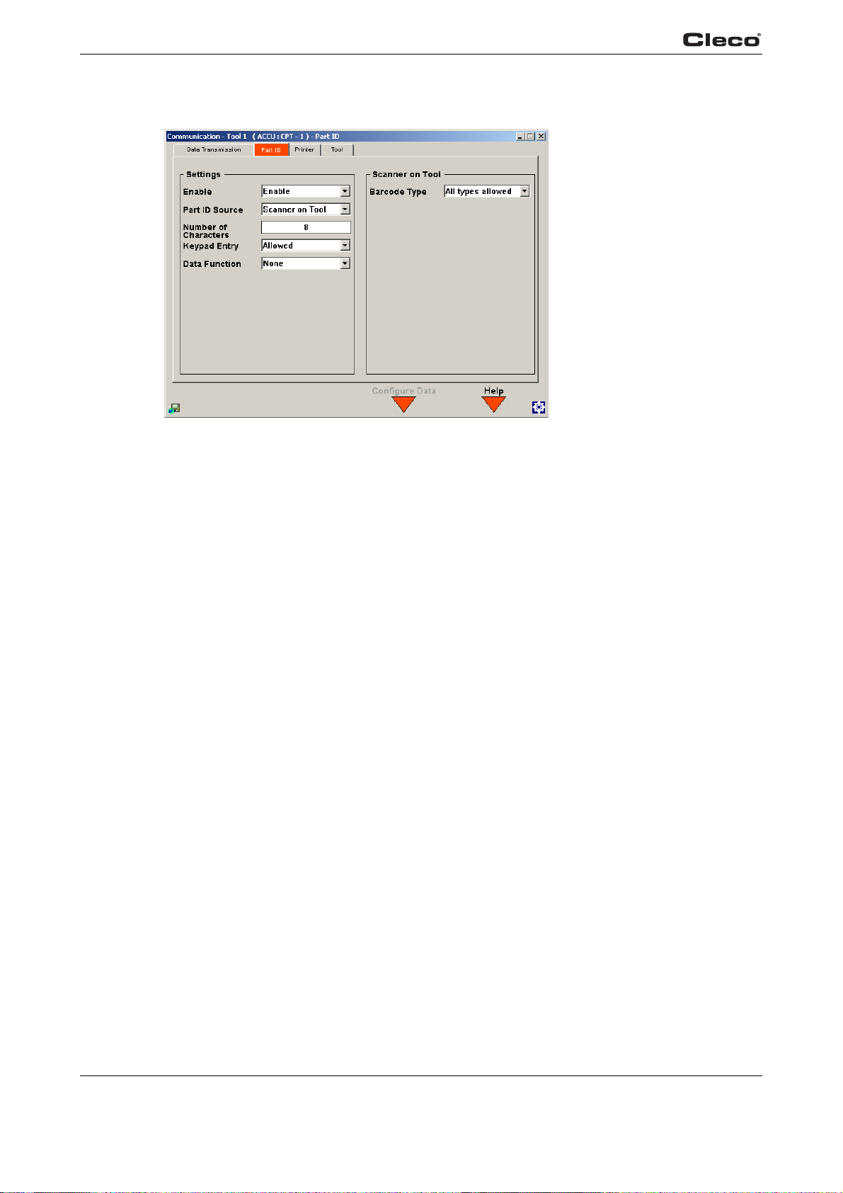
Programming
3
3.7.2 Communication / Part ID
Fig. 3-21: Part ID
c00405en.bmp
comprtid.txtS
The Part ID configuration screens allow the user to specify the interface and functionality of the
Part ID used on the Run Screen and archived with the rundown data. Changes to the Part ID and
Configuration Data edit screens are saved when the Communication screen is exited (Run
Screen or Navigator button pressed). At this time the request to save the configuration is confirmed with a password dialog box.
The Part ID may be entered manually from the run screen or scanned from the tool using a barcode reader. A Part ID may consist of any sequence of alphanumeric characters, including
aces.
sp
58 P1934E/EN 2009-04 en03c381.fm, 23.04.2009
Page 59

Settings
Programming
3
Enable Defines the level of functionalit
Not Defined The Part ID interface is completely disabled. No Part ID
inform
ation is present on the Run Screen, and a part ID
string of “(Disabled)” is archived with each rundown. The
part ID is not transmitted with the standard serial protocol
output data.
Enable The Part ID interface is enabled, and is present on the
Run Screen
tool. Following a rundown, the Part ID or the string “(Not
Valid)” is archived with the rundown data. The Part ID is
transmitted with the standard serial protocol output data.
Enable Interlocked
Print Interlocked
The Part ID interface is enabled, and is present on the
Run Screen. A vali
tool. Following a rundown, the Part ID is archived
with the rundown data. The Part ID is transmitted with
the standard serial protocol output data. Following
either a good rundown (linking disabled) or good
linking sequence (linking enabled) the Part ID is
invalidated and the tool is disabled.
The Part ID interface is enabled, and is present on the
Run Screen. A
tool. Following a rundown, the Part ID is archived
with the rundown data. The Part ID is transmitted with
the standard serial protocol output data. The Part ID
is valid and the tool is enabled until the operator
presses the <F1> “Print” key on the Run Screen.
At this time, the Part ID is invalid
and any rundowns which have not previously been
printed are sent to the parallel port printer interface.
y of the Part ID
. A valid part ID is NOT REQUIRED to run the
d Part ID is REQUIRED to run the
d Part ID is REQUIRED to run the
vali
ated, th
e tool is disabled,
Part ID Source Defines the source of the Part ID (such as a barcode reader at the serial
rface, barcode reader on the tool, gateway, or the Fieldbus). Fieldbus is
inte
only available if the Part ID option has been enabled in the Advanced / Field-
bus screen.
Number of
cters
Chara
Defines the length of the Part ID, not including any termination characters
which may be sent by the barcode reader.
• Valid values are 1 to 25
en03c381.fm, 23.04.200 9 P1934E/EN 2009-04 59
Page 60

Programming
3
Keypad Entry Defines whether or not a Part ID can be entered manually
Allowed You can enter a work piece ID manually. To do so, select
the Wo
via the key pad or an external keyboard.
Disallowed The Part ID can not be entered manually from the run
screen.
ta Function Allows the tool functionality to be automatically controlled based on the Part
Da
ID. Se
e “Configure Data” below.
None The Part ID characters have no control over the tool func-
tionality. The <F3> “Configure Data” Softkey on the Part
ID conf
Note: setting this option
figure Data table entries to be lost.
Configuration The position and value pairs in the configuration table can
be
cial functions enables the <F3> "Configuration" softkey.
Yo
table and assign tool functions to them, which are then
controlled based on the part ID.
rk piece ID field at the Run Screen and input data
iguration screen is disabled.
to “None” does NOT cause Con-
used to control the function of the tool. Activating spe-
u can enter position and value pairs in the configuration
Barcode type Defines which barcode type is read by the barcode scanner on the tool.
Activating the
scanne
on the tool
Configuration
Part ID: Open the configuration table by pressing the <F3> Configur
nication / Part ID screen. A maximu
to functions. When the station controller receives a new Part ID, the entries in the table are read.
If an entry in the Part ID corresponds to one of the defined "Values" in the relevant "Position", the
assigned "Function" is activated.
The entries appear in a table in the top section of the screen. The Position, Va
PG/TG (Product Group/Tightening Group) entry fields are located at the bottom of the screen.
Pressing the <F1> Add softkey transfers the current values to the entry fields in the table. All values are checked before being transferred to the table. New entries are always added at the END
of
the table line you wish to delete. Select Cancel to cancel the delete function. Press the <F3> Part
ID softkey to open the Part ID configuration screen.
r
the table. Pressing the <F2> Delete softkey opens a dialog window for entering the number of
The barcode scanner on the tool is activated by pressing the start button.
• If a barcode is the condition for a rundown to be started, the barcode
scanner
has been read successfully, pressing the start button again starts the fastening sequence.
• If a barcode is not a condition to start a rundown, you can use the menu
scann
ally activate a read cycle. Afterwards, the bar
whenever the start button is pressed. If the barcode has been read successfully, pressing the start button again starts the fastening sequence. If
the
ms. If the barcode cannot be read within 3 seconds or there is an interruption by opening the start switch, the acoustic signal emits 3 beeps in rapid
success
is activated as soon as the start button is pressed. If the barcode
er
or the programmable left function key <F1> on the tool to manu-
code scanner is activated
barcode has been read successfully, the acoustic signal beeps for 500
ion.
ation softkey in the Commu-
m of 12 position and value pairs can be entered and assigned
l
ue, Function and
60 P1934E/EN 2009-04 en03c381.fm, 23.04.2009
Page 61
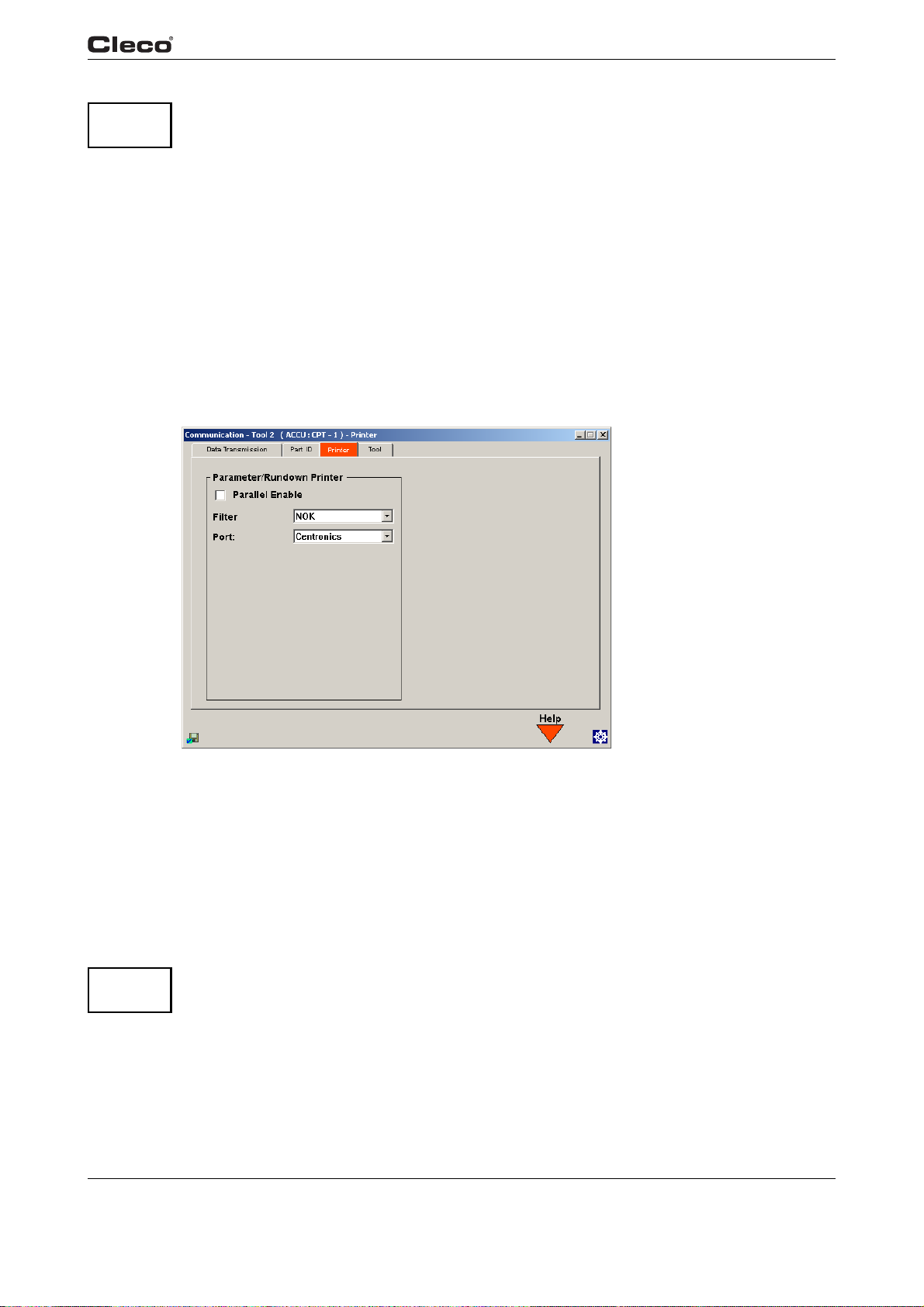
When a Part ID is compared with the positions and values in the table, the system stops
ATTE N-
TION!
reading the table as soon as an entry is found where t
correspond. The positions (digits) of the Tool ID are numbered from left to right.
position 1 <Number of characters>
Value Each alphanumerical character
Function Use product group X, use tightening group X, tool enable, lock
App/Grp 1-255 if "Use product group X" function is selected
comprtid.txtE
3.7.3 Communications / Printer
he Part ID and definition in the table
tool
1-8 if "Tightening group X" function is selected
Ignored if "Release" or "Locked" function
is selected.
Programming
3
Fig. 3-22: Printer
commprin.txtS
From this screen the user can configure the setup for the Parameter/Rundown Printer. If activated, the rundown data are automatically se
nt to the selected port once a complete page of data
has been committed to the queue. Rundown data that have not been printed are sent to the
printer when a new print command is issued (usually, by selecting Print <F1> at the Run Screen).
The filter parameters allow the user to choose to have all, OK or NOK rundown data printed. This
filter applies both to automated printing of rundown data and manual printing of rundown data (by
selecting Print <F1> at the Run Screen).
ATTENTION!
commprin.txtE
en03c381.fm, 23.04.200 9 P1934E/EN 2009-04 61
The Printer must be on before you switch on your TME. This will guarantee correct initialization
of the printer.
c00291en.bmp
Page 62
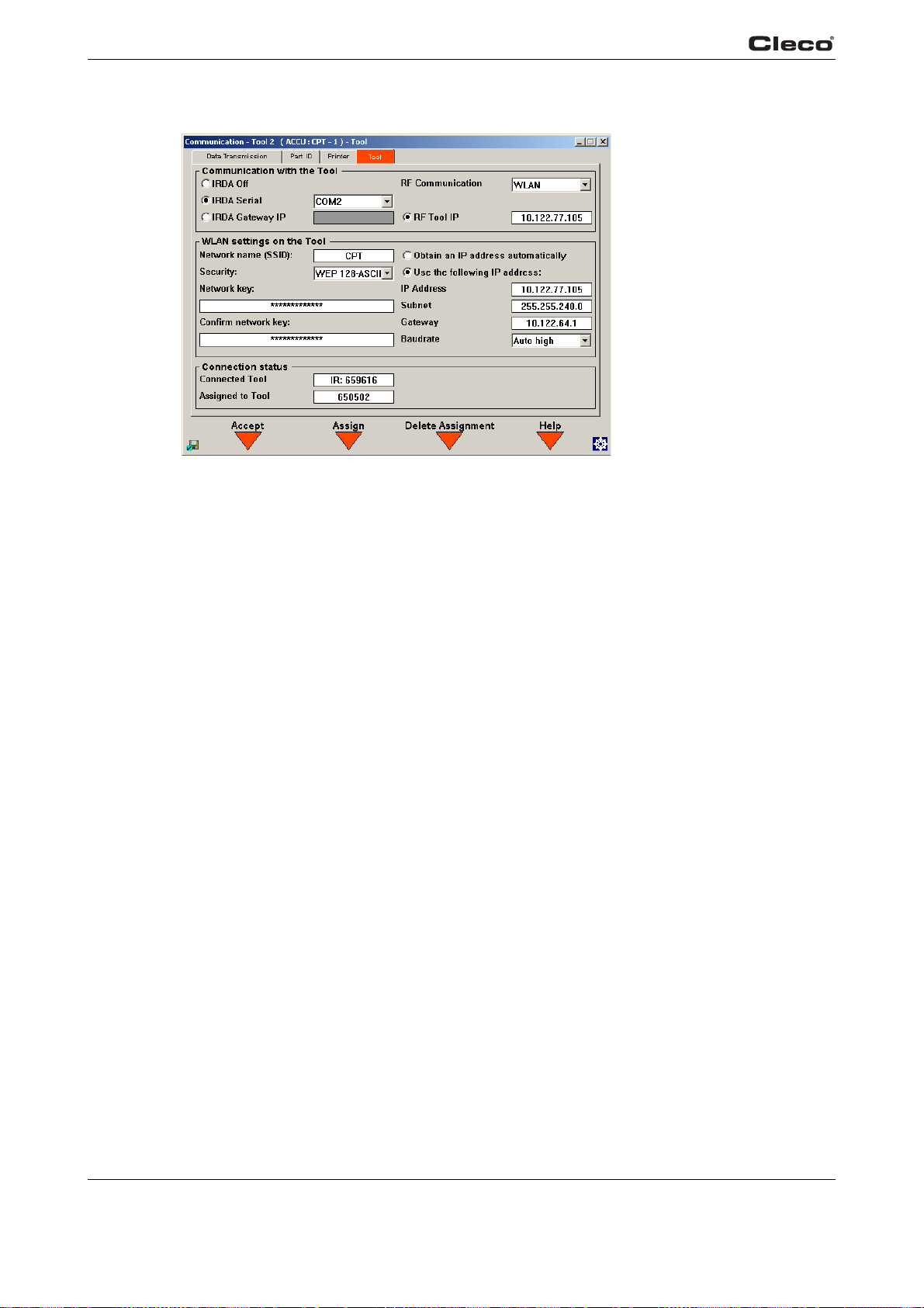
Programming
3
3.7.4 Communication / Tool
Fig. 3-23: Communication - Tool 1
c00582en.bmp
commtma.txtS
This screen defines how the controller communicates with the cordless tool. The display and settings of the parameters pertain to the currently selected tool number. The selected tool number is
in the title bar.
shown
ed
All cordless tool series are equipped with an infrar
ing on the tool types, wireless transmission can be activated.
• 17BPR… / 47BAR… Communication via 868 MHz
• 17BPW… / 47BAW… Communication via WLAN (2.4 GHz)
• 17BPX… /47BAX… Communication via WLAN (2.4 GHz)
The Con
selected tool number (number in the title bar).
Connected Tool If a connection to the tool can be established using the entered settings,
Assigned to
To
nection status ar
o
l
ea shows the connection to the tool as well the serial number of the
e s
erial number of the tool is displayed. For an infrared connection, the
th
prefix IR appears in front of the serial number. For an infrared connection,
the prefix RF appears in front of the serial number. If no connection can be
established, Not connected is shown. Continual attempts are made to
establish a connection to the tool.
Shows the serial number of the tool to which the selected tool number has
been assigned. The selected tool number is shown in the title bar. The
selection is made in the Run Screen. If no tool is assigned, Not assigned is
displayed. The displays and settings in other screens with the same tool
number refer to the tool assigned here.
interface for data communication. Depend-
tke
y
Accept sof
<F1>
62 P1934E/EN 2009-04 en03c381.fm, 23.04.2009
Pressing the Accept softkey <F1> accepts the settings, and an attempt is
made to establish a connection to the tool using the entered parameters.
Page 63
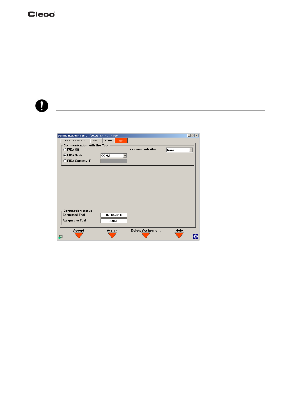
Programming
3
NOTE
Assign softkey
<F2>
Delete Assignment softkey
3>
<F
If this tool was assigned to a different system, a reassignment is also necessary, as otherwise
data consistency cannot be guaranteed.
Pr
essing the Assign softkey <F2> assigns the connected tool to the
selected tool number. An assignment is possible only if a connection exists
to the tool. An assignment deletes any existing rundown data in the tool.
Pressing the Delete Assignment soft
the tool serial number to the selected tool number.
3.7.5 Infrared data transmission
key <F3> deletes the assignment of
Fig. 3-24: Communication - Tool 1
The Communication with the Tool area defines the port to which the infrared data transmission is
connected.
IRDA Off Disables infrared data transmission.
IRDA Serial Select this if you want to use a serial interf
sion. Multiple tools of the same controller can use the same serial interface
ared data transmission. Once an interface has been enabled, it is no
for infr
longer available for other tasks, such as barcode or serial rundown data
transmission.
IRDA Gateway IPSelect this if using a gateway (Ethernet/serial, order no. 961159) for infra-
red data transmission. If you enable this, you have to enter the IP address
e gateway.
of th
en03c381.fm, 23.04.200 9 P1934E/EN 2009-04 63
ace for infrared data transmis-
c00704en.bmp
Page 64

Programming
3
NOTE
If you use Ethernet, port 4001 must not be blocked by a firewall, etc.
RF Communication
NOTE
You must press the <F1> softkey to apply the settings you have modified.
Select None if you
3.7.6 868 MHz data transmission
For 17BPR… and 47BAR… series tools with 868 MHz data transmission, wireless data transmission is possible instead of, or in addition to, infrared data transmission.
If an infrared connection and a wireless connection exist simu
takes priority.
The wireless parameters are configured manually on the tool, using the function keys, in the
dio settin
Ra
The following three parameters are used to define the wireless data transmission between the
station and the tool.
base
Parameter Range
Radio channel 868 MHz: 1–3
Network ID 1–16
Too l I D 1–4
gs submenu.
want to use infrared data transmission only.
ltaneously, the infrared connection
The radio channel and the network ID are required once for each base station. The tool ID differs
fo
each tool connected to a base station. If multiple systems in the same vicinity use the same
r
radio channel, each system must have a different network ID. If multiple base stations are in
close proximity to each other, they should use different radio channels rather than different network IDs.
The channel, network ID and tool ID of the tool and the TMEB-200 / TMEB-COM / TMEC must
tc
h.
ma
64 P1934E/EN 2009-04 en03c381.fm, 23.04.2009
Page 65
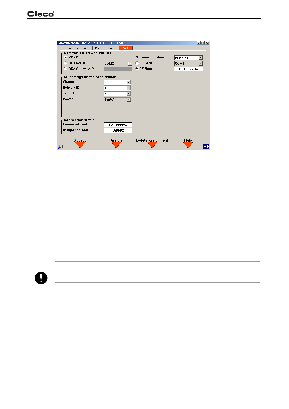
Programming
3
c00705en.bmp
NOTE
Fig. 3-25: Communication - Tool 1
The Communication with the Tool area defines the ports to which the infrared data transmission
and the base station are connected.
IRDA Off Disables infrared data transmission.
IRDA Serial Select this if you want to use a serial inter
sion. Multiple tools of the same controller can use the same serial interface for infrared data transmission. Once an
is no longer available for other tasks, such as barcode or serial rundown
data transmission.
IRDA Gateway IP Select this if using a gateway (Ethernet/serial, order no. 961159) for infra-
red data transmission. If you enable this, you have to enter the IP address
e gateway.
of th
If you use Ethernet, port 4001 must not be blocked by a firewall, etc.
RF
Communication
Select 868 MHz if you want communication with the tool to t
868 MHz.
ace for infrared data transmis-
f
interface has been enabled, it
ake place via
RF Serial Select this if you want to use a serial interface f
the base station. Once an interface has been enabled, it is no longer available for other tasks, such as barcode or serial rundown dat
en03c381.fm, 23.04.200 9 P1934E/EN 2009-04 65
or data transmission with
a transmission.
Page 66

Programming
3
NOTE
RF
Base station
If you use Ethernet, port 4001 must not be blocked by a firewall, etc.
Enter the radio settings of the base station in the RF S
Channel Used to select the radio channel. For the 868 MHz version, you can select
Network ID Defines the network identification for the tools connected to a base station.
Tool ID Specifies the tool identification for the tools connected in a network. The
Select this if you want data transmission to the base station to take place
via Ethernet. If you enable this, you have to enter the IP address of the
base station. Refer to the base station's operating manual for more information about setting up the base station.
ettings of the Base Station area.
chan
nel 1 to 3. You can operate no more than 4 tools per channel. To prevent interference with the wireless tran
with the same radio channel should be as located as far apart from each
other as possible.
can operate no more than 4 tools per network ID. The network ID can
You
be anywhere in the range from 1 to 16.
ID can be anywhere in the range from 1 to 4.
tool
smission, different base stations
NOTE
Power Used to select the transmission power. To avoid interfering with other
de
vices in this frequency range, set the transmission power as low as possible.
For 868 MHz, the maximum transmission power depends on the selected
an
nel.
ch
• If channel 1 is selected, you can choose between 1, 5, 10, and 25 mW
for the t
• If channel 2 or 3 is selected, you can choose either 1 or 5 mW for the
transmissi
You must press the <F1> softkey to apply the settings you have modified.
ransmission power.
on power.
66 P1934E/EN 2009-04 en03c381.fm, 23.04.2009
Page 67
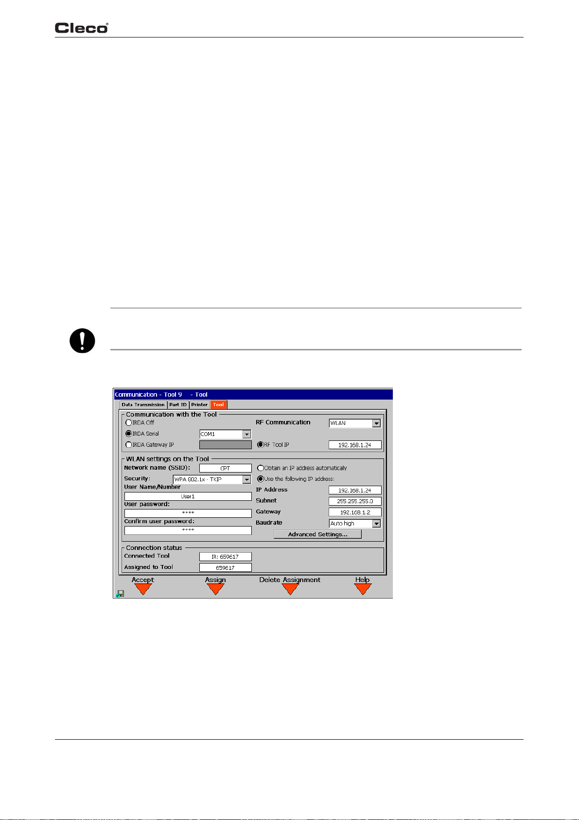
3.7.7 WLAN data transmission
For 17BPW…/17BPX… and 47BAW…/47BAX… series tools with WLAN data transmission,
wireless data transmission is possible instead of, or in addition to, infrared data transmission.
If an infrared connection and a wireless connection exist simu
takes priority.
The initial configuration of the WLAN p
face. If the WLAN parameters already exist in the to
infrared connection is required and you need only enter the IP address.
Programming
3
ltaneously, the infrared connection
arameters in the tool must take place via the infrared inter-
ol, for example from earlier programming, no
NOTE
Prerequisites for communication with
Different functions are available for WLAN data tran
tion. Additional functions are available for 17BPX… and 47BAX… series tools. This chapter
s attention to the relevant differences.
draw
• Port 4001 must not be blocked by a firewall.
• The access point must n
• Entry of the access data is case-sensitive.
• The tools support channels 1 – 11 (2.412 – 2.462 GHz). Disable automatic channel selection
on
the access point and use channels 1 – 11 only.
The installation instructions for setting up a wireless network are contained in"Installation instructions – Cordless EC tool with WLAN dat
Tool setup with existing WLAN parameters on tool
ot block the MAC address of the tool.
the tool via WLAN
smission depending on the tool configura-
a transmission".
Fig. 3-26: Communication - Tool 1
en03c381.fm, 23.04.200 9 P1934E/EN 2009-04 67
c00706en.bmp
Page 68
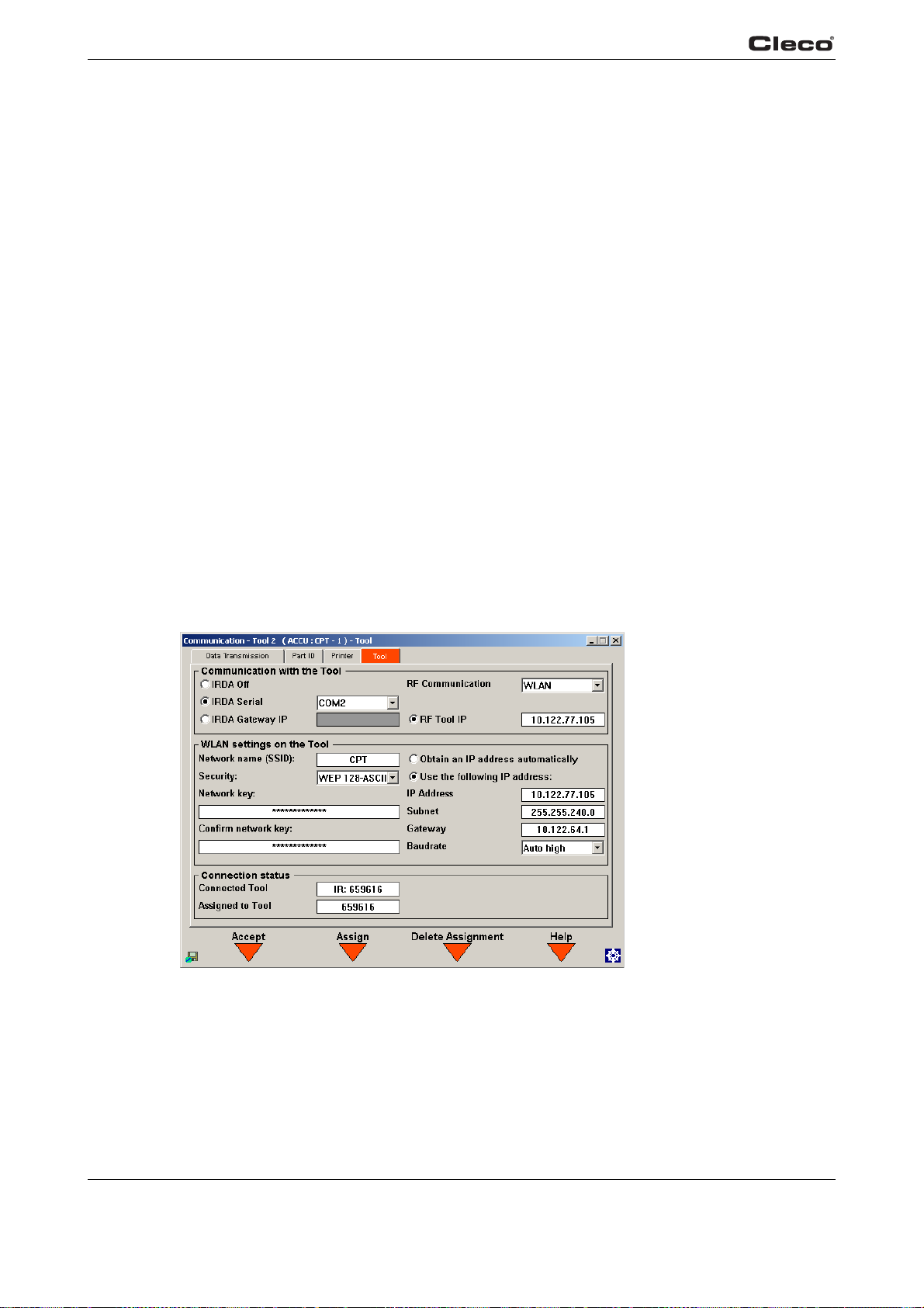
Programming
3
The Communication with the Tool area defines the IP address to be used for communication.
RF Communication
RF Tool IP Enter the IP address of the tool here. The IP address of the tool is displayed
Tool setup without existing WLAN parameters on tool
If there are no WLAN parameters on the tool or the p
tings are configured via the infrared interface. To do so
to the tool via the infrared interface.
Setup takes place in this sequence:
1. Enable the infrared connection.
2. Accept by pressing softkey <F1>, A
3.
Enter the WLAN settings.
4. Accept the settings by pressing softkey <F1>, Accept.
5. Enter the IP address in the field for RF To
6. Accept by pressing softkey <F1>, Accept.
7
. Assign the selected tool number to the tool using softkey <F2>, Assign.
8. Disable infrared data transmission.
9. Accept by pressing softkey <F1>, Accept.
Select WLAN if you want
WLAN.
on
the tool in the WLAN wireless transmission menu.
No settings are required in the WL
the communication with the tool to take place via
AN settings on the Tool area.
arameters are not current, the WLAN set-
, it is necessary to establish a connection
ccept.
ol IP.
Fig. 3-27: Communication - Tool 1
68 P1934E/EN 2009-04 en03c381.fm, 23.04.2009
c00707en.bmp
Page 69

Programming
The Communication with the Tool area defines the ports to which the infrared data transmission
and the base station are connected, as well as the IP address to be used for wireless communication.
IRDA Off Disables infrared data transmission.
3
NOTE
IRDA Serial Select this if you want to use a serial inter
sion. Multiple tools of the same controller can use the same serial interface for infrared data transmission. Once an interface has been enabled, it
longer available for other tasks, such as barcode or serial rundown
is no
data transmission.
IRDA Gateway IP Select this if using a gateway (Ethernet/serial, order no. 961159) for infra-
red data transmission. If you enable this, you have to enter the IP address
e gateway.
of th
If you use Ethernet, port 4001 must not be blocked by a firewall, etc.
RF
Communication
RF Tool IP Enter the IP address of the tool. If you are not using DHCP, you have to
You must select WLAN if yo
place via WLAN.
ente
r the IP address from the IP address field. If DHCP is enabled, the IP
address obtained is displayed on the tool in the WLAN wireless transmission
menu.
u want the communication with the tool to take
ace for infrared data transmis-
f
Enter the WLAN settin
Network name
(SSID)
Encryption / Network key
The network name can be a string of no more than 31 alphanumeric characters. The network name must match the network name (SSID) of the access
point.
Specifies the authentication and data encryption method. The encryption
me
selection depends on the tool used. Additional functions are available for
17BPX… and 47BAX… series tools.
Open
WEP 64-ASCII
WEP 64-HEX
WEP 128-ASCII
WEP 128-HEX
gs on the Tool in the corresponding area.
Entry is case-sensitive.
thod specified under Security must match that of the access point. The
No encryption is enabled.
No network key is required.
The network key must consist of 5 alphanumeric
characters.
The network key must consist of 10 characters, *from 0 –
9 and from A – F.
The network key must consist of 13 alphanumeric
characters.
The network key must consist of 26 characters,
from 0 – 9 and from A – F.
en03c381.fm, 23.04.200 9 P1934E/EN 2009-04 69
Page 70

Programming
3
WPA-PSK - WEP
WPA/WPA2-PSK TKIP
WPA/WPA2-PSK AES
CISCO LEAP
WPA 802.1x WEP
The WPA protocol with pre-shared key (PSK) and WEP
encryption is used to establish a connection. The network key must consist of 8 – 63 alphanumeric characters.
If this encryption is enabled, it can take up to 30 seconds
t
ore the settings in the tool.
to s
The WPA/WPA2 protocol with pre-shared key (PSK) and
TKIP encryption is used to establish a connection. The
network key must consist of 8 – 63 alphanumeric characters. If this encryption is enabled, it can take up to 30
co
nds to store the settings in the tool.
se
The WPA/WPA2 protocol with pre-shared key (PSK) and
CCMP (AES) encryption is used to establish a connection. The network key must consist of 8 – 63 alphanu-
is
meric characters. If this encryption
up to 30 seconds to store the settings in the tool.
Lightweight Extensible Authentication Protocol (LEAP) is
used to establish a connection to an authentication
server. Entry of user name and password is required.
Only available for tools from the 17BPX…
series.
The WPA protocol, IEEE 802.1x authentication (EAP)
and WEP encryption are used to establish a connection.
Entry of user name and password is required.
Only available for tools from the 17BPX…
series.
enabled, it can take
and
47BAX…
and
47BAX…
Network key
co
nfirmation
User name /
Passwor
Password confirmation
Obtain an IP
addr
automatically
(DHCP)
d /
ess
WPA 802.1x TKIP
WPA 802.1x - AES
If WEP encryption is active, entry and confirmation of the network key is
required.
Specifies the user name and password comb
LEAP or 802.1x network.
Only available for tools from the 17BPX…
es whether the IP address is obtained automatically from a DHCP
Defin
v
er or access point. If automatic address assignment is used, it must be
ser
ensured that the DHCP server or access point always uses the IP address
assigned for this specific tool.
The automatically obtained IP address of the tool is displayed on the tool in
L
the W
AN wireless transmission menu.
The WPA protocol, IEEE 802.1x authentication (EAP)
and TKIP encryption are used to establish a connection.
Entry of user name and password is required.
and
and
47BAX…
47BAX…
Only available for tools from the 17BPX…
series.
The WPA protocol, IEEE 802.1x authentication (EAP)
and CCMP (AES) encryption are used to establish a con-
nection. Entry of user name and password is required.
Only available for tools from the 17BPX…
series.
ination for authentication in a
and 47BAX… series.
70 P1934E/EN 2009-04 en03c381.fm, 23.04.2009
Page 71

Programming
3
NOTE
Use the following IP address
IP Address Used to enter an IP address for the tool. The IP address
Subnet mask Used to enter the subnet mask number for the tool. The subnet mask
Gateway Used to enter the IP address of the default gateway for the tool. The
Baud rate Defines the data transmission speed between the access point and the
vanced
Ad
settings...
You must press the <F1> softkey to apply the settings you have modified.
Defines that you are entering the IP address, subnet mask and gateway
manually.
must consist
of four numbers between 0-255, separated by decimal points.
number
decimal points.
de
rated by decimal points.
tool.
Displays screen with advanced settings.
Only available for tools from the 17BPX…
must consist of four numbers between 0-255, separated by
fault gateway must consist of four numbers between 0 – 255, sepa-
and 47BAX… series.
en03c381.fm, 23.04.200 9 P1934E/EN 2009-04 71
Page 72
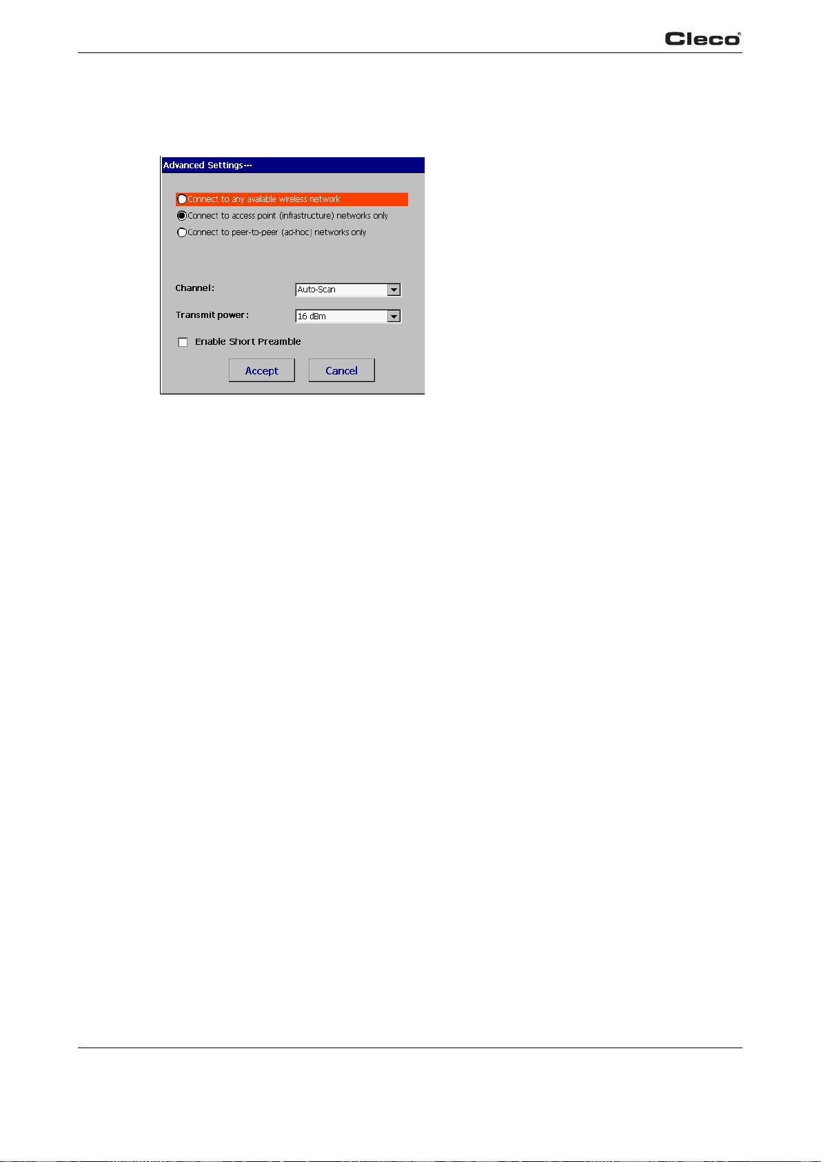
Programming
3
Advanced settings
Only available for tools from the 17BPX…
and 47BAX… series.
c00728en.bmp
commtma.txtE
Fig. 3-28: Advanced settings.
Connect to any
available available wireless
ork
netw
Connect to
s point
acces
(infrastructure)
networks only
Connect to peer-
er (ad-hoc)
pe
tonetworks only
Channel Specifies the radio channel used. Selecting Auto scans
Transmit power Specifies the transmission power of the tool.
Enable Short
Preamb
le
ast
Specifies that a connection to the Infr
can be established.
Specifies that only a connection to Access Points can be established.
Specifies that only a connection to Point to Point networks (Ad-hoc) can be
established.
available networks.
Activates Short Preamble.
ructure and Ad-hoc network types
all channels for
72 P1934E/EN 2009-04 en03c381.fm, 23.04.2009
Page 73

3.8 Tool Setup
Programming
3
c00293en.bmp
toollist.txtS
ATTENTION!
toollist.txtE
Fig. 3-29: Tool Memory
The data in the tool memory of the selected tool are displayed. For battery-operated tools, a
redundancy feature is not currently available. The Torque Cal. field (+/- ±20% of nominal) can be
edited to correct the torque calibration of the selected tool.
If the tool is offline, the last data used is displayed.
to the fact that the tool is not connected and data can only be displayed. When you leave this
screen, the data is not adopted if the tool is not connected and switched on at the time of
acknowledgment!
If the tool is online, the data currently being used is displayed and changes are accepted.
A new tool must always be assigned at the Communication/Tool screen and be accepted at the
ol Settings screen.
To
Calibration using an external (Master) Transducer and Torque Monitoring corresponding
to an external standard is required only in the following cases:
Before using a new tool for the first time, after the tool is repaired; in the event of recurring reading errors, regularly every 6 months or 100,0
according to quality assurance requirements.
Each transducer's calibration values should be documented for future reference.
You can set a limit for battery"Low Level" voltage under Battery. If the voltage falls
limit, a message appears on the LCD of the tool, which the machine operator must acknowledge
by pressing the left button on the tool. The battery should then be charged immediately in the
charging station.
When the screen is called, the user is alerted
00 cycles (whichever comes first) or
below this
en03c381.fm, 23.04.200 9 P1934E/EN 2009-04 73
Page 74
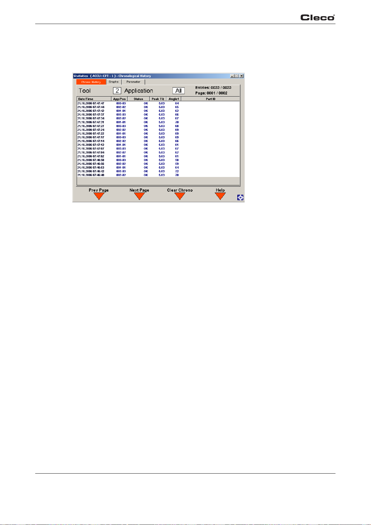
Programming
3
3.9 Statistics
3.9.1 Statistics / Chronological History
chrono.txtS
Fig. 3-30: Chronological History
You can display a chronological summary (Chrono History) of rundowns for a particular application or for all applications, using a filter correspond
ters. This summary includes time, date, App/step, status, torque, angle and part number.
Use Previous Page <F1
XXXX / YYYY at the top right show the number of chronological entries corresponding to the filter
criteria / the total number of chronological entries in the data
shows the page currently being displayed / the total number of pages of entries corresponding to
the filter criteria. The Clear Chrono <F3> Softkey allows the user to delete all rundowns.
> and Next Page <F2> to scroll through this summary. The entries:
ing to the criteria under Statistics / Parame-
base. The page XXXX / YYYY
c00297en.bmp
74 P1934E/EN 2009-04 en03c381.fm, 23.04.2009
Page 75
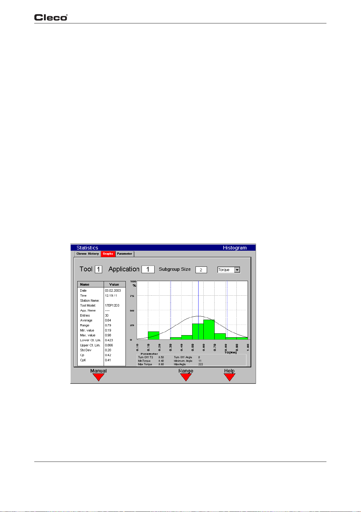
The following abbreviations are used to designate the fault that has occurred
TMAX Maximum fastening time exceeded
TS Depth sensor signal was active at start or was disabled in
the
urse of the fastening sequence
co
Tq< Torque too low
Tq> Torque too high
Ang< Angle Low
ANG> Angle High
IIT Motor power required is too high
IP Current overload in output section
CAL Transducer calibration error
ENC Angle encoder fault
OFF Transducer offset error
RC Rundown terminated by disabled start signal
Programming
3
NOK Result is not okay
OK Result is OK
chrono.txtE
3.9.2 Statistics / Charts
Fig. 3-31: Charts Histogram
en03c381.fm, 23.04.200 9 P1934E/EN 2009-04 75
c00357en.bmp
Page 76
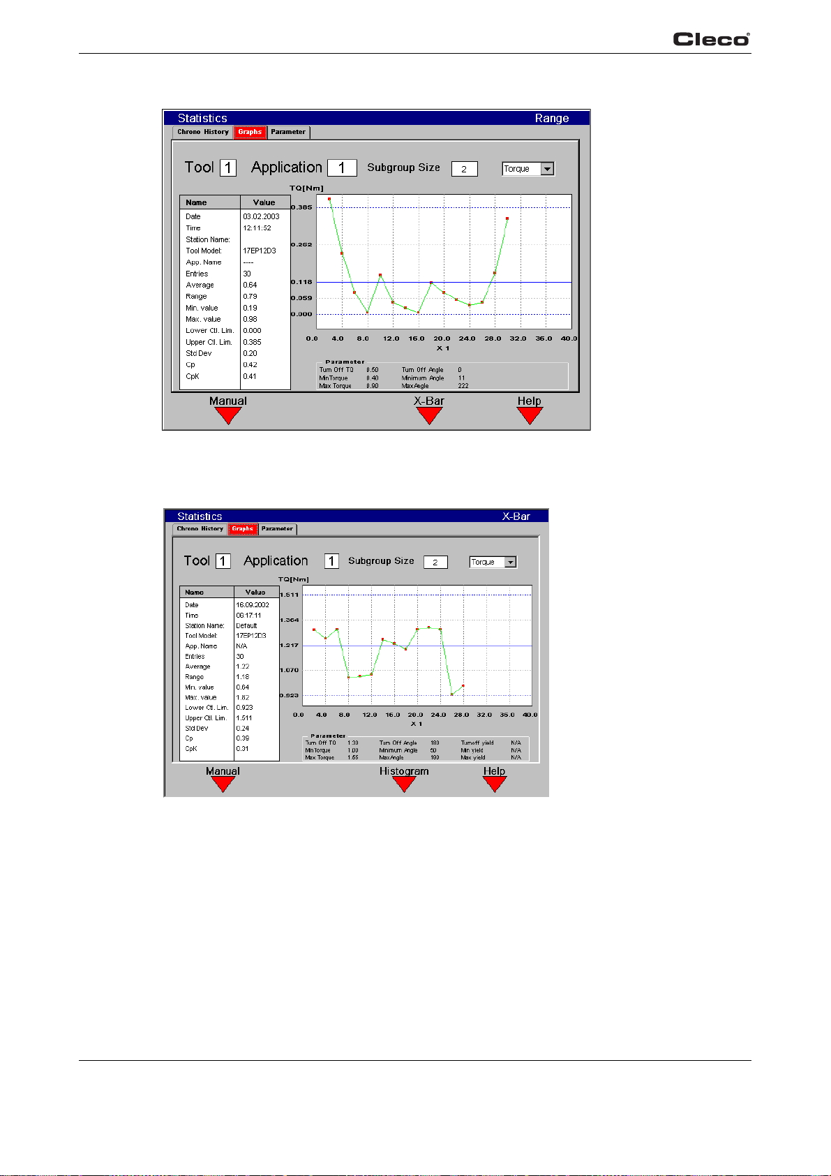
Programming
3
c00361en.bmp
graphs.txtS
Fig. 3-32: Range
Fig. 3-33: Chart / X-Bar
The Statistics / Charts screens are used to display the statistics for the selected rundowns in both
summary and graph form. Refer to Chapter 4 for a discussion of the significance of statistical values. Rundowns are selected via Application in th
criteria in the Statistics / Parameters screen. You can also specify a size for the subgroup (2-25)
or toggle between torque and angle calculations. The <F3> softkey is used to switch between
Histogram, Range and X-Bar graphs. The <F1> softkey is used to toggle between manual and
automatic update. In auto mode, statistics are recalculated and the sequence redrawn when a
e Graphic display and further filtered using filter
c00358en.bmp
76 P1934E/EN 2009-04 en03c381.fm, 23.04.2009
Page 77
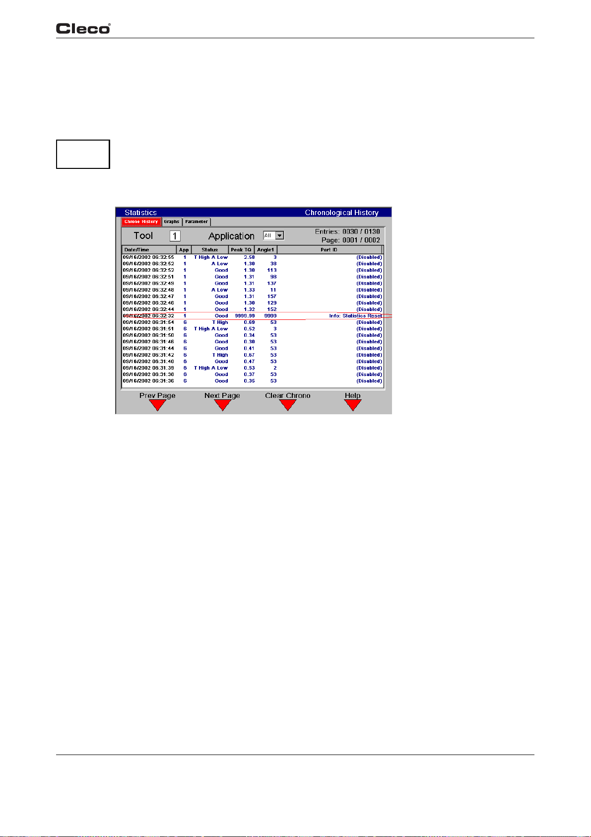
Attention:
graphs.txtE
Programming
new rundown is added to the chronological summary (Chrono History). In manual mode, new
calculations are performed only if you press the <F2> key, Refresh. When working with large
data sets, it is advisable to select manual update mode for improved performance.
The left side of the display contains a text summary of st
bottom of the screen displays relevant programmed parameters for the currently selected application.
When one of these programmed parameters (Min/Max/Shut-off torque/angle) is changed,
it invalidates all previous rundowns for this applicat
Min/Max/Shut-off value is changed, an entry is made in the Chrono History noting that the
rundowns are no longer valid for statistical calculations:
atistical calculations. The table at the
ion for statistical calculations. When a
3
Fig. 3-34: Chronological History
c00359en.bmp
en03c381.fm, 23.04.200 9 P1934E/EN 2009-04 77
Page 78
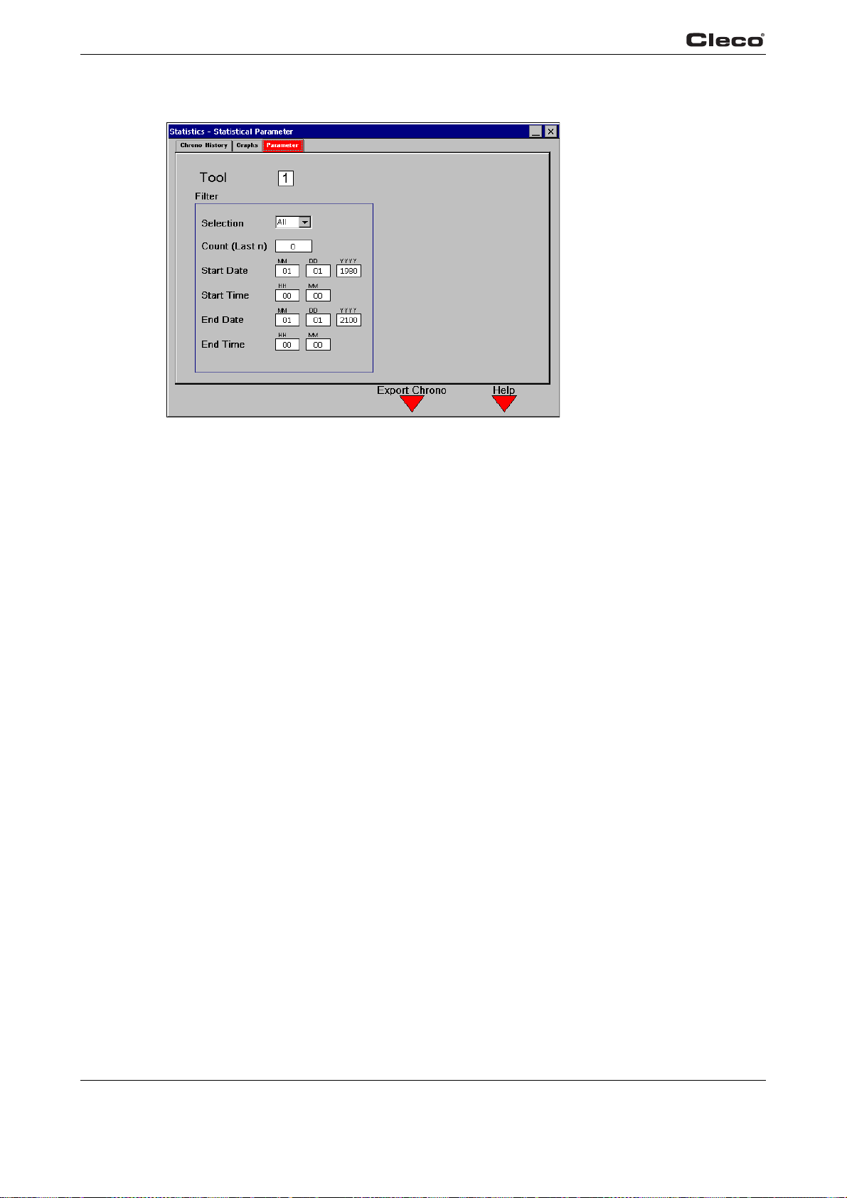
Programming
3
3.9.3 Statistical Parameter
Fig. 3-35: Statistical Parameter
c00401en.bmp
statpara.txtS
statpara.txtE
From the Parameter Screen the user is able to apply a filter to the chrono data.
Filter
1. From the pulldown menu, select All, OK or NOK ru
2. Enter a number into the Numbe
3. Supply a Start Date/Time and an End Date/Time.
These parameters are checked and updated every time the selected
when you leave the Parameter screen. The parameters selected at this screen apply for the
Chrono History and Charts.
Export Chrono
This softkey allows the user to send the filter
Printer. A file name may be entered.
r (last) field. Entering a value of 0 disables this filter criterion.
ed data to the removable storage media or the
ndowns.
field is changed or
78 P1934E/EN 2009-04 en03c381.fm, 23.04.2009
Page 79
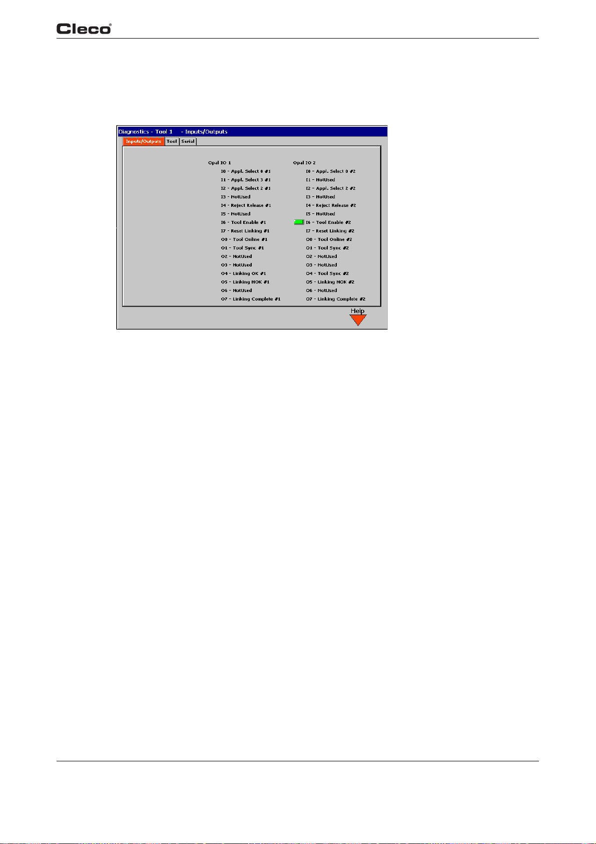
3.10 Diagnostics
3.10.1 Inputs / Outputs – only for TMEB-200 / TMEC
Programming
3
opaldiag.txtS
opaldiag.txtE
Fig. 3-36: Inputs / Outputs
The External I/O are available at the Phoenix connectors.
This screen will give a live update of all system I/O. If a green
description, then it is active.
Otherwise the space next to the I/O desc
The display for Diagnosis Inputs/Outputs shows the st
tool number allocated to the signal appears on the right of the signal.
ription will be blank indicating it is inactive.
atus of the +24V digital inputs/outputs. The
box is shown next to the I/O
c00298en.bmp
en03c381.fm, 23.04.200 9 P1934E/EN 2009-04 79
Page 80
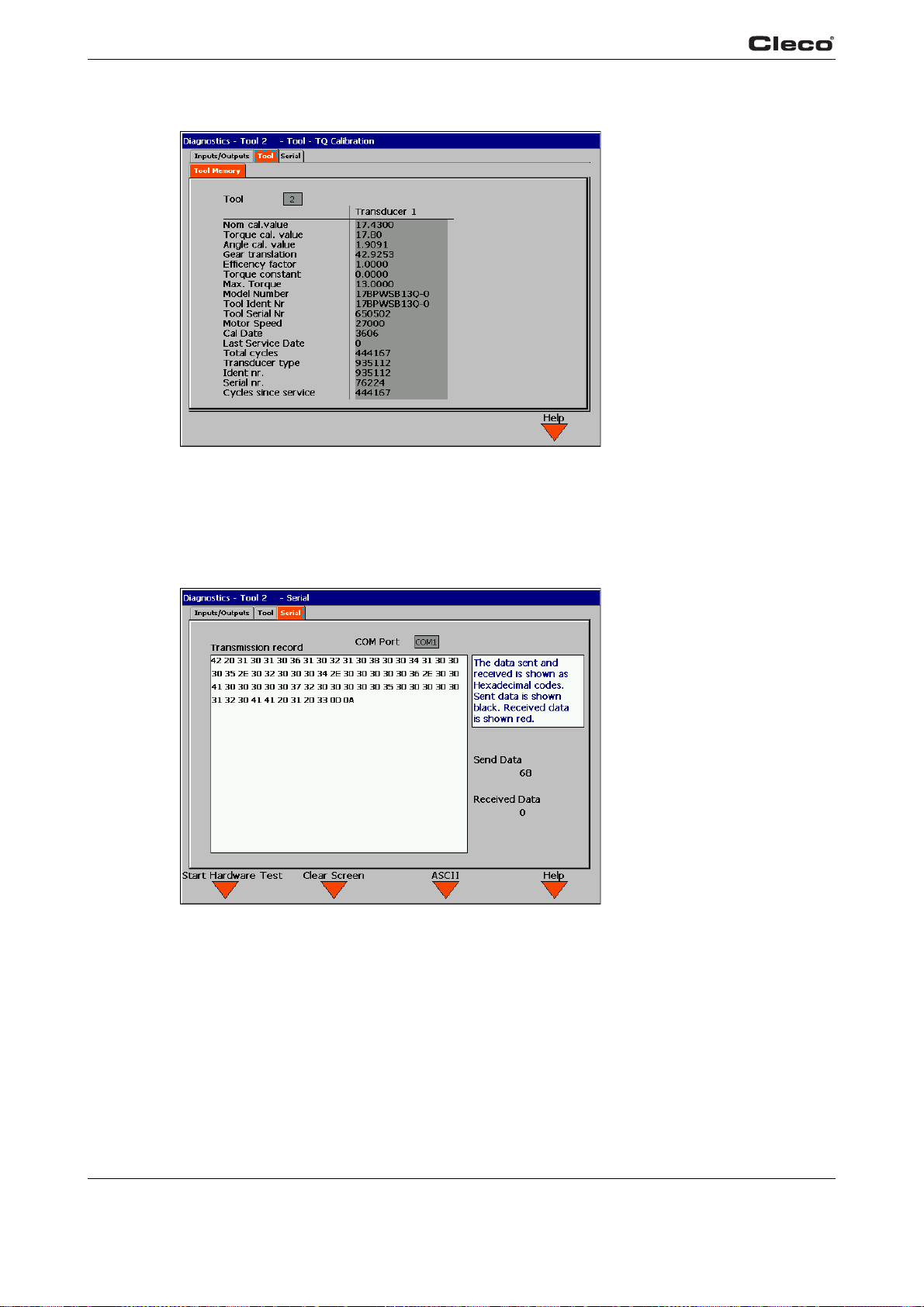
Programming
3
3.10.2 Tool / Tool Memory
Fig. 3-37: Tool / Tool Memory
c00316en.bmp
testiden.txtS
The data stored in the memory of the connected tool is updated continuously.
testiden.txtE
3.10.3 Serial
Fig. 3-38: Serial Port Diagnostics
c00305en.bmp
serial.txtS
The serial diagnostics allows the user to test the selected COM port by displaying sent (black
text) and received data (red text).
The “Start Hardware Test” transmits 10 characters. It read
s back a byte based on the CTS signal. For this test an external Adapter with shorted pins is necessary. Note that serial data display
is only avail
The Clear Screen
able with serial data transmission configured as “Standard” or “CT01 3964R”.
<F2> Softkey will clear the displayed bytes
The <F3> Softkey toggles the transmission record display between ASCII and hexadecimal.
80 P1934E/EN 2009-04 en03c381.fm, 23.04.2009
Page 81
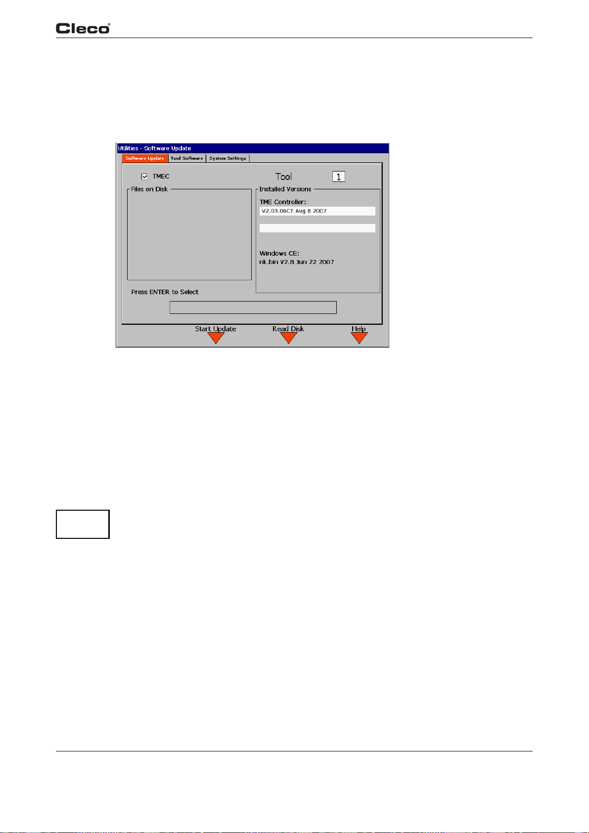
serial.txtE
3.11 Utilities
3.11.1 Utilities / Software
Programming
3
updateso.txtS
ATTENTION!
updateso.txtE
Fig. 3-39: Update Controller Software
The installed software version is displayed.
Only for TMEB-200 / TMEC:
The selection button is used to select an
update for the TMEB-200 / TMEC. The current installed
version is listed for each module. As the software is updated a progress bar will be displayed. It is
not possible to update the tool software or the Windows CE operating system of the TMEB-200 /
EC using this screen.
TM
The Start Update <F
The Read Disk
2> softkey loads the selected file into the selected module.
<F3> softkey reads the removable storage media and displays its contents.
The system must not be switched off during Software Update!
c00306en.bmp
en03c381.fm, 23.04.200 9 P1934E/EN 2009-04 81
Page 82
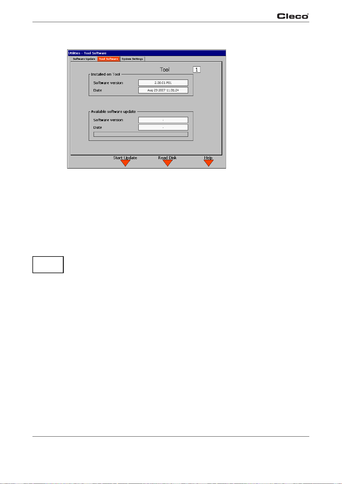
Programming
3
3.11.2 Utilities / Tool
Fig. 3-40: Tool
c00583en.bmp
updateto.txtS
ATTENTION!
updateto.txtE
If a tool is connected, the installed software version and software date are displayed under
Installed on Tool.
Use the Read Disk <F3
software version and software date.
The Start Update <
As the software is updated, a progress bar is displayed
software or the Windows CE operating system from this screen.
The system must not be switched off during Software Update!
The battery must have a sufficient charge that the tool will not shut down due to undervoltage!
> softkey to read the removable storage media and display the available
F2> Softkey will load the selected file into the tool.
. It is not possible to update the TMEB
82 P1934E/EN 2009-04 en03c381.fm, 23.04.2009
Page 83
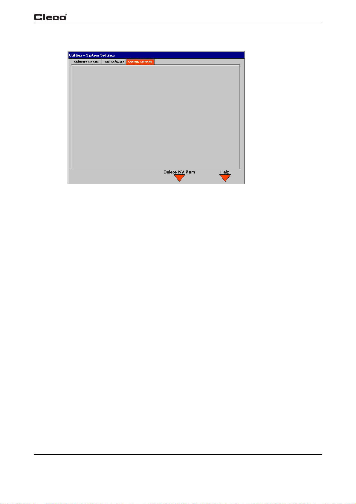
3.11.3 Utility / System settings – only for TMEB-200 / TMEC
Programming
3
c00391en.bmp
UtilSysS.txtS
UtilSysS.txtE
Fig. 3-41: System settings
The Delete NV Ram softkey deletes existing printing jobs.
en03c381.fm, 23.04.200 9 P1934E/EN 2009-04 83
Page 84
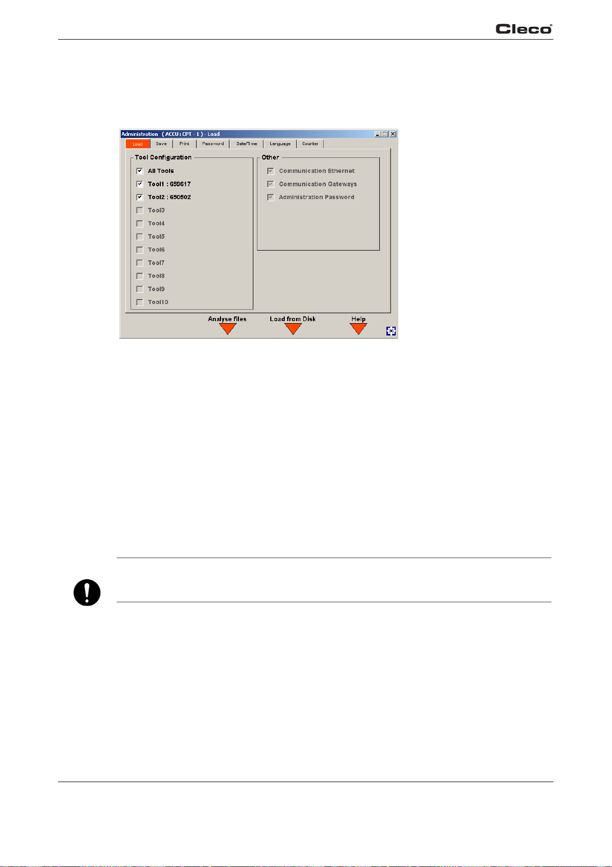
Programming
3
3.12 Administration
3.12.1 Administration / Load
load.txtS
NOTE
load.txtE
Fig. 3-42: Load / Save
From the load screen, the user can load/restore the parameters.
Before the parameters can be loaded from the storage medium, the user must first analyze the
pa
rameter file and read out the information for the stored tools. The user can select the desired
parameters by pressing the Analyze file softkey; then,the list of the available tools is displayed
under Tool Configuration.
in the
The user can select one or more tools
loaded.
Inputs and Outputs are always loaded as a whole, regardless of which tools are selected.
The configurations of Commu
Password are always loaded from the storage medium along with the tool parameters.
The Load settings <F3> so
The selected Application/Tightening group number in the Run Screen
is loaded together with the tool p
nication/Ethernet, Communication/Gateways and Administration/
ftkey loads the parameters of the selected tools.
arameters.
list, and only the parameters from these tool(s) are
c00307en.bmp
84 P1934E/EN 2009-04 en03c381.fm, 23.04.2009
Page 85
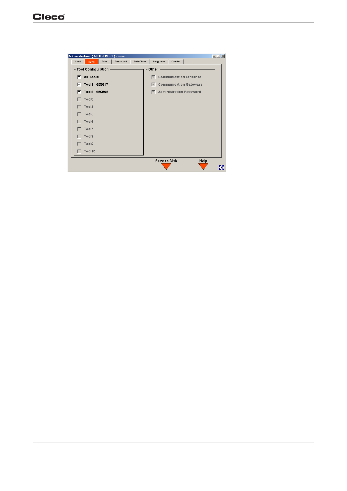
3.12.2 Administration / Save
Programming
3
c00718de
loadsave.txtS
loadsave.txtE
Fig. 3-43:
You can save parameters to a file in this screen.
The available (enabled) tools are displayed under Tool Con
You can select individual or all tools in order to save their parameters.
Inputs and Outputs are saved as a whole, regardless of which tools are selected.
Settings for Commun
The parameters are saved with <F3>, Save pa
ication Ethernet and Administration Password are always saved.
rameters.
figuration.
en03c381.fm, 23.04.200 9 P1934E/EN 2009-04 85
Page 86
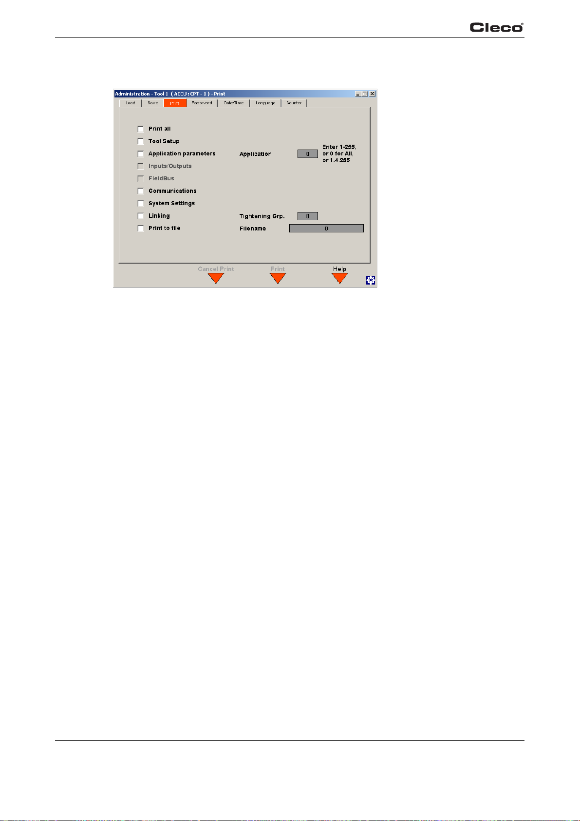
Programming
3
3.12.3 Administration / Print
Fig. 3-44: Print
c00308en.bmp
setuppri.txtS
setuppri.txtE
Using the check boxes, the user can select the parameters to print. These will be sent to the
printer defined in the Communications setup or to a file on the removable storage media if
selected.
The Print
<F3> Softkey will start printing.
86 P1934E/EN 2009-04 en03c381.fm, 23.04.2009
Page 87
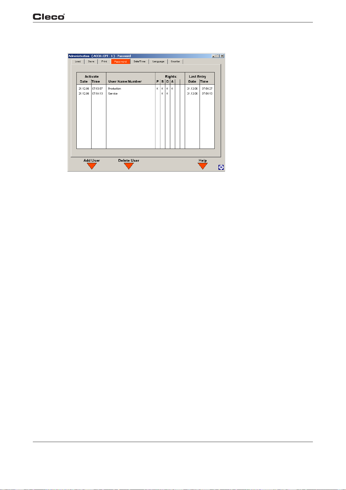
3.12.4 Administration / Password
Programming
3
c00309en.bmp
password.txtS
password.txtE
Fig. 3-45: Password
The Password displays the active users and corresponding rights. There are different rights
available for Programming, Statistics, Diagnostics and Administration. The date and time of the
last entry changes automatically when parameters are changed. The Password function supports up to ten different users plus a master password.
1> it
Pressing Add User <F
“Administration” rights he will get them automatically.
Pressing Delete User <F2
“Administration” rights he will get them automatically.
is possible to add a new user. If the first user does not activate the
> it is possible to delete a user. If the last user does not have the
en03c381.fm, 23.04.200 9 P1934E/EN 2009-04 87
Page 88
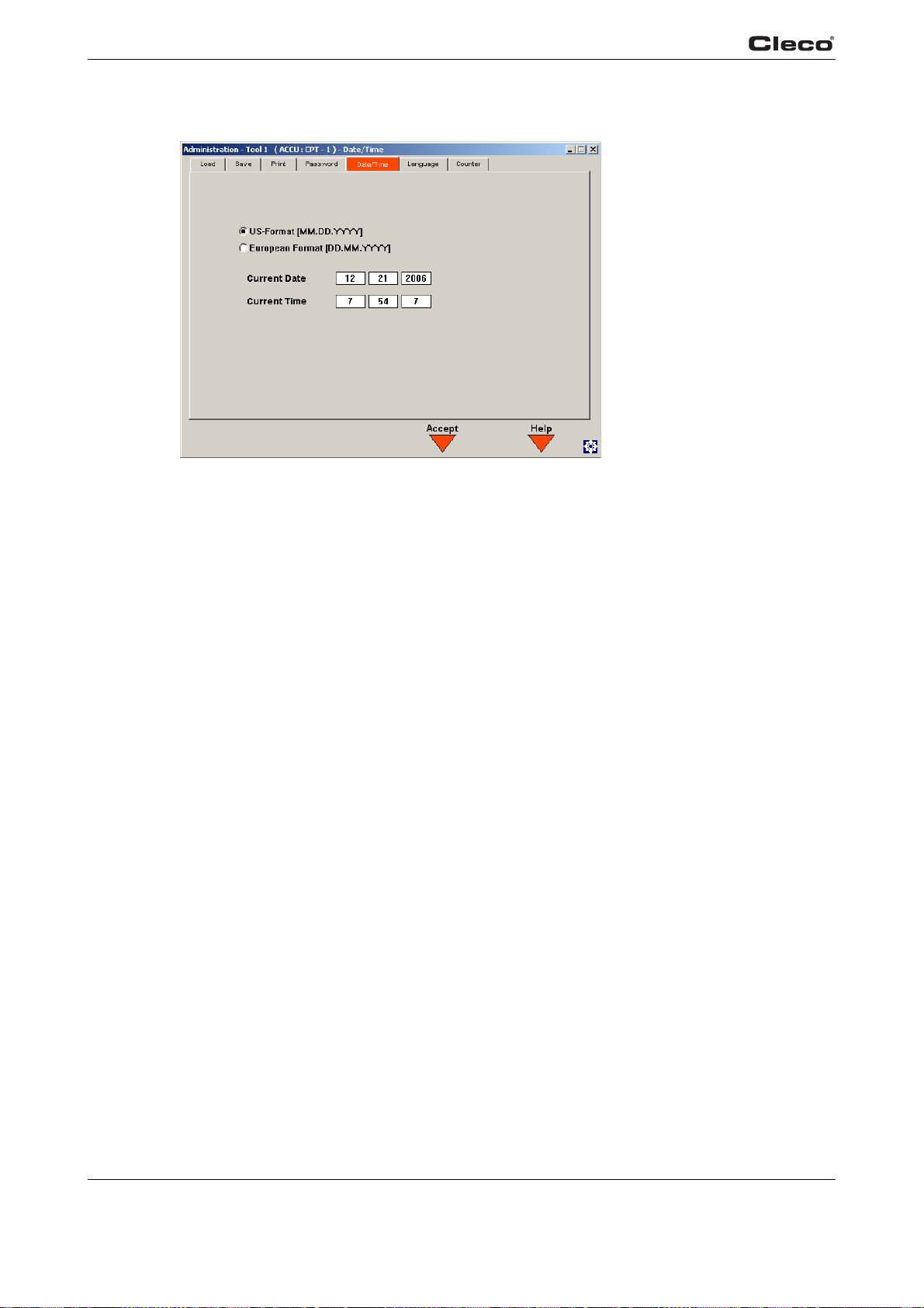
Programming
3
3.12.5 Administration / Date & Time
Fig. 3-46: Date & Time
c00310en.bmp
datetime.txtS
datetime.txtE
When the tool is"Online", the tool's system time is displayed; at other times, the screen is grayed
out and cannot be edited.
Enter the appropriate settings for time and date.
Using the radio buttons the user can select European or US format for time and date.
Automatic summer/winter time settings are not supp
System time and date are always updated on both the TMEB and at the tool when you press the
Accept <F3> so
ftkey.
orted by the tool.
88 P1934E/EN 2009-04 en03c381.fm, 23.04.2009
Page 89
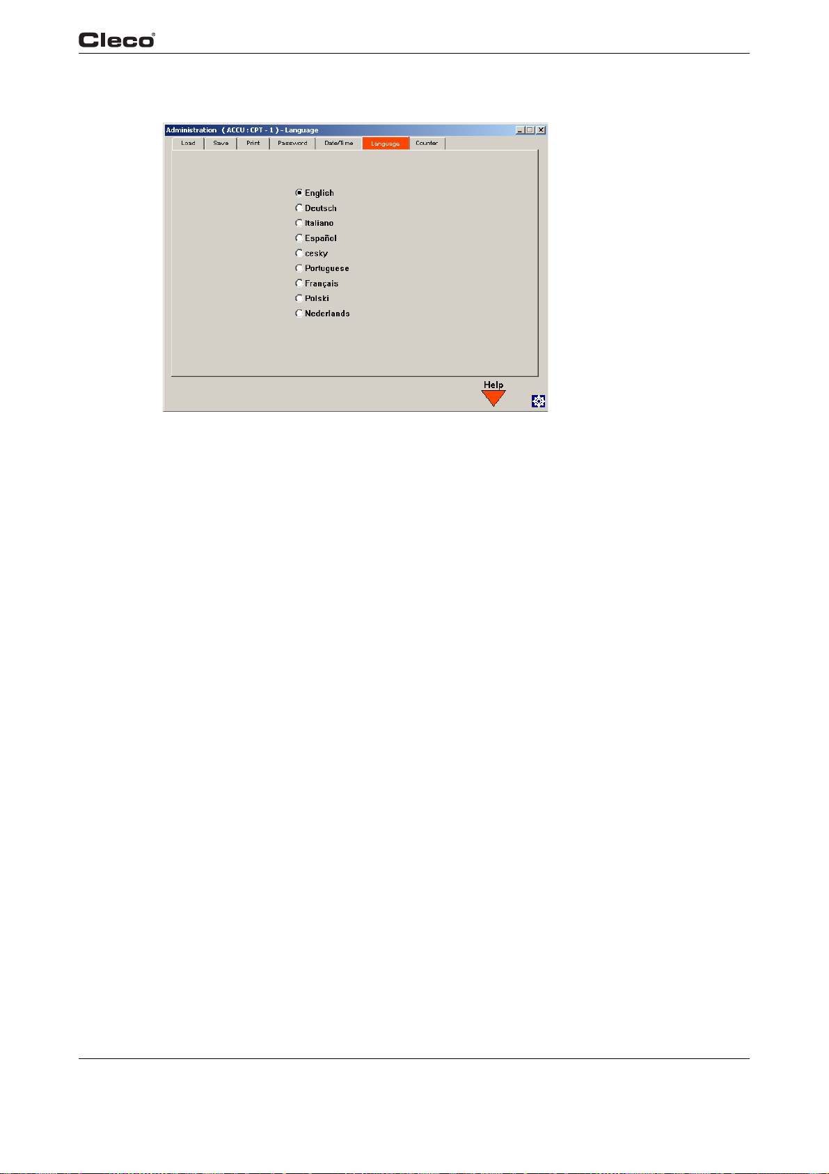
3.12.6 Administration / Language
Fig. 3-47: Language
Programming
3
c00360en.bmp
language.txtS
language.txtE
The Administration / Language display is used to select the language for the operator interface.
Use the up arrow and down arrow keys to highlight the desired language and press <ENTER> to
confirm.
en03c381.fm, 23.04.200 9 P1934E/EN 2009-04 89
Page 90
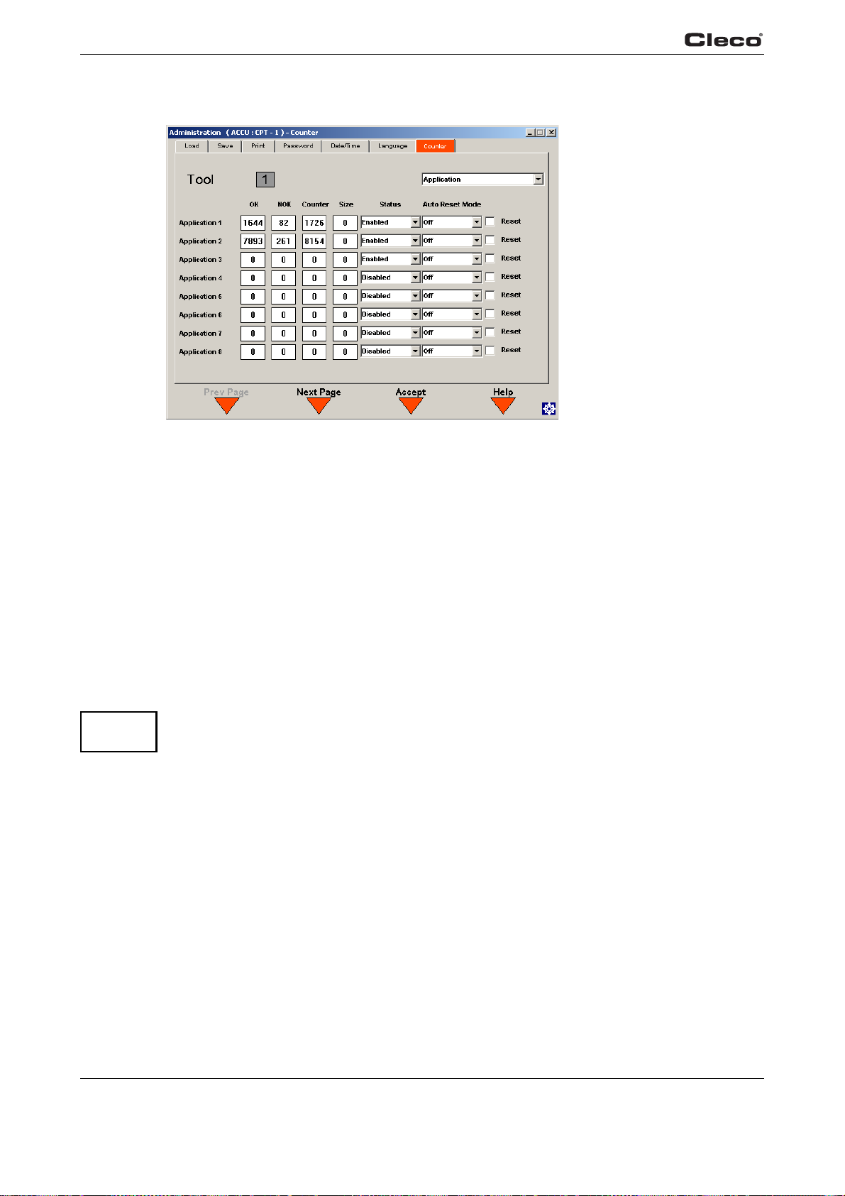
Programming
3
3.12.7 Administration / Counters
c00365en.bmp
counters.txtS
ATTENTION!
counters.txtE
Fig. 3-48: Counters
From the Administration / Counters screen, the user can activate, deactivate or reset all available
counters. There are counters available for each application (1-255) and for each tightening group
(1-8). Toggle the display between Application and Tightening Group by selecting either Application or Step at the pull-down menu.
You can activate or reset any counter by highlighting the desired operation in the"Status" pull-
o
wn menu and then pressing the ENTER key.
d
In"Auto Reset Mode", the counter can be used as a"Batch Co
automatically reset to zero once the total number of rundowns (OK + NOK = Number) or the
number of successful rundowns (OK = Number) matches the value programmed in the Number
field.
You can reset any counter manually be highlighting the Reset
key.
Counters are not activated, deactivated or reset until the Accept <F3> softkey is pressed,
and the correct password (if activated) and confirmation have been entered.
unter". In this mode, the counter is
che
ck box and pressing the Enter
90 P1934E/EN 2009-04 en03c381.fm, 23.04.2009
Page 91
Troubleshooting
4
4 Troubleshooting
Problem Possible cause Action
General
No parameter is displayed in the Ba
Application Builder.
No torque plot is displayed in the oscilloscope screen.
Not all or none of data
in Chron
displayed.
Digital +24 V outputs
tive.
not ac
sic
o
History is
Rundown sequence
othe
r than two-stage
SEQ 11/30 or SEQ 11/
50 is programmed.
Torque plot data transmission is deactivated.
Filter active. ➔ In the Statistics/Parameter screen of the con-
Other tools of this controller are used more
ently
frequ
Output parameter is not
configured.
Hardware connection is
incorrect.
.
➔ Use Standard Application Builder to display
and edit the parameter.
➔ In the Run Screen/Configure screen of the
controller, check the Upload Graphic Options
parameter.
troller, check whether any filter parameter is
active.
➔ The controller stores the most recent run-
downs, independent of the tool
➔ In the Advanced Application Builder / Outputs
screen of the controller, check that the signal is
programmed to correspond to the output.
➔ Check if the connection is set up, see 2.2.7
Input / output connectors, page 18
s.
Problem Possible cause Action
General – Tool
Tool does not start if
reverse switch is active.
Tool light not active. Deactivated by param-
Operating menu of tool
y
not, or onl
enabled.
Free
value
Could not reach the
expected numb
rundowns with one
battery charge.
partly,
speed parameter
is not reached.
er of
Backoff speed parameter is set to 0 rpm.
eter setting.
Disabled by parameter
setting.
Battery voltage is too
low.
Battery is not fully
charged.
Low voltage warning is
not set to minimum
lue.
va
During tightening
quen
ce, high torque
se
is required, for example
with coated screws.
Battery has already
cycled too of
ten.
➔ Adjust the backoff speed value in the Standard
Application Builder screen of the controller.
➔ Adjust the parameter for Tool light in the
Advanced Application Builder/System Settings
screen of the controller.
➔ Activate the Enable Tool menu parameter in
the Advanced Application Builder/System Set-
tings screen of the controller.
➔ Use a fully charged battery.
➔ Use only fully charged batteries.
➔ In the Tool Setup screen of the controller, set
the value for Low Level to 17.5 Volts.
➔ If high torque is required for a longer period of
time, e.g. for several turns, then the number of
rundowns with one battery charge is significantly reduced.
➔ After 800 charge cycles the capacity is reduced
to about 60%.
91e_Trouble shooting en bedingt.fm, 23.04.2009 91
Page 92
Troubleshooting
4
Problem Possible cause Action
Infrared data communication between controller and tool
No infrared data
communication
n co
betwee
tool.
ntroller and
Wrong port is selected
ecti
for conn
controller.
Selected port is used
serial dat
for
sion.
on with the
a transmis-
➔ Check the port settings for infrared (IRDA)
communication in the Communication/Tool
screen of the controller.
Note: If the setting
to press Accept <F1> in order to apply the settings.
➔ Check that the tool holder is connected to
selected port.
➔ In the Communication/Data Transmission
screen of the controller, check whether serial
data transmission is enabled (the protocol is
set to anything except NONE), and whether
the same port is being used. If so, select a different port or disable serial data transmission.
Check
same port cannot be used for serial data transmission and infrared data communication with
the tool.
s are changed, it is necessary
all available tools as necessary. The
Problem Possible cause Action
WLAN data communication between controller and tool
No WLAN
communication
between controller and
tool.
IP address of tool is not
entered correctly on the
controller.
Tool is not configured
th
correct WLAN
wi
parameter values.
WLAN network settings of the controller
nd th
e access point
a
differ.
MAC add
the access
active.
A firewall blocks port
4001.
The RF channel at the
acce
the tool-supported
range.
Tool is already
as
controller.
ress filter of
point is
ss point is out of
signed to a different
➔ Check in the Communication/Tool screen of
the controller that the IP address of the tool is
entered in the RF Tool IP field. The IP address
of the tool is displayed on the tool in the WLAN
RF settings submenu.
Note: If the settings are changed, it is necessary
to press Accept <F1> in order to apply the settings.
➔ Configure the WLAN settings of the tool in the
Communication/Tool screen of the controller
via infrared communication.
➔ In the Communication/Tool screen of the con-
troller, check that the settings of the access
po
int match the wireless network settings (Net-
work name, Security, Network key).
➔ Add the MAC address of the tool to the
address list of the access point. The MAC
address of the tool is displayed on the corresponding label above the battery, and in the
WLAN RF sett
➔ Reconfigure the firewall so that the specific IP/
MAC address of the tool can use port 4001.
➔ Change the channel setting of the access point
to a channel between 1 and 11.
➔ Check whether any other controller has
already established a connection to this tool.
That means another controller use same IP
address.
ings submenu.
92 91e_Trouble shooting en bedingt.fm, 23.04.2009
Page 93
Problem Possible cause Action
WLAN data communication between controller and tool
WLAN communication
partly interrupted.
Distance between
access point and tool is
too great.
Tool is also assigned to
f
ferent controller.
a di
Too much traffic on the
reless netwo
wi
rk.
➔ Check the signal strength in the WLAN RF set-
tings submenu of the tool. For stable communi-
cation, the first value (N) should be greater
15. If the value is less than 15, move the
than
access point closer to the tool.
➔ Check whether this tool (IP address) is
assigned to any other controller. If so, delete
the assignment on the other controller. A tool
can only be assigned to one controller.
➔ Reduce traffic on the wireless network.
Deactivate torque plot data transmission.
Problem Possible cause Action
868 MHz data communication between controller and tool
No serial communication
is possible between the
controller and the base
station. (Error displayed
after Accept <F1> is
pressed in Communica-
tion/Tool.)
Wrong serial cable is
.
used
Wrong port is selected
for connectio
n with the
controller.
Selected port is used for
a
serial dat
transmission.
Power outlet not active.
➔ Use a null modem cable (crossed).
➔ In the Communication/Tool screen of the con-
troller, check the port settings for RF Serial.
Note: If the settings are changed, it is necessary to
press Accept <F1> in order to apply the settings.
➔ Check that the serial cable is connected to the
selected port.
➔ In the Communication/Data Transmission
screen of the controller, check whether serial
data transmission is enabled (the protocol is set
to anything except NONE), and whether the
same port is being used.
➔ If so, select a different port or disable serial data
transmission.
➔ Check all available tools as necessary. The
same port cannot be used for serial data transmission and data communication with base station tool.
➔ Check the voltage at the outlet socket where the
base station is plugged in for power supply.
Troubleshooting
4
91e_Trouble shooting en bedingt.fm, 23.04.2009 93
Page 94

Troubleshooting
4
Problem Possible cause Action
868 MHz data communication between controller and tool
No Ethernet communication is possible
between the controller
and the base station.
(Error displayed after
Accept <F1>) is pressed
in Communication/Tool.)
No 868 MHz data communication is possible
e
tween controller and
b
tool.
Wrong Ethernet cable is
.
used
IP address of the base
a
tion is not entered
st
correctly on the controller.
IP address and subnet
r
mask a
same range.
A firewall blocks port
40
Base station is already
connected
controller.
Powe
Settings are not configured correctly.
Distance between base
st
great.
e not in the
01.
to a different
r outlet not active.
a
tion and tool is too
➔ A crossover cable is required if the base station
is directly connected to the controller. If the base
station is connected to a switch, a standard
patch cable is required.
➔ In the Communication/Tool screen of the con-
troller, check that the IP address of the base
tion is entered in the RF Base station field. If
sta
the IP address of the base station is unknown
use the Network Enabler Administrator program, which is included with each base station.
Note: If the settings are changed, it is necessary to
press Accept <F1> in order to apply the settings.
Without network administration, it is necessary for
the IP address and subnet mask of the controller to
be in the same range as those of the base station.
➔ Enter the same subnet mask for both IP
addresses and use the same first three numbers for the IP addresses
and base station.
E.g.:
IP address controller: 192.168.1.xxx
IP address base station: 192.168.1.xxx
Subnet mask: 255.255.255.000
➔ Reconfigure the firewall so that the specific IP/
MAC address of the tool can use port 4001.
➔ Check whether any other controller has already
used the same IP address for RF communication (RF Base station).
➔ Check the voltage at the outlet socket where the
base station is plugged in for power supply.
➔ In the Communication/Tool screen of the con-
troller, check that RF
correspond to the settings of the tool, which are
displayed in the 868MHz RF settings submenu
of the tool. The settings for Channel, Network ID
and Tool I D must match.
If channel 1 is selected, the distance can be up to
98.4 ft (30 m). If channel 2 or 3 is selected, the distance can be up to 32.8 ft (10 m).
➔ Increase output power on base station and on
the tool, or move the base station closer to the
tool.
on both the controller
settings of the base station
94 91e_Trouble shooting en bedingt.fm, 23.04.2009
Page 95
Problem Possible cause Action
868 MHz data communication between controller and tool
RF communication is
partly interrupted.
Distance for RF communication is too short
Distance between base
station and tool is too
great.
Output power is too low.
Too much traffic on the
same chan
nel.
Too many tools on the
same chan
nel.
Other 868 MHz devices
the same frequency.
on
Antenna of the base station is not tightened
securely
.
Output power is too low.
Location of the base station bad.
If channel 1 is selected, the distance can be up to
30 m. If channel 2 or 3 is selected, the distance can
be up to 10 m.
➔ Move the tool close to the base station to check
whether communication is successful. If so,
increase output power on base station and on
the tool, or move the base station closer to the
tool.
➔ Increase the output power of the base station
and of the tool. If channel 1 is selected, you can
choose up to 25 mW for the output power. If
channel 2 or 3 is selected, you can choose 1
mW for the output power of the base station and
5 mW for the output power of the tool.
➔ Reduce traffic on the wireless network. Deacti-
vate torque plot data transmission.
➔ Use different channels for different base sta-
tions.
➔ Use a different channel.
➔ Manually tighten the base station antenna.
➔ Increase the output power of both the base sta-
tion and the tool.If channel 1 is selected, you
can choose up to 25 mW for the output power. If
channel 2 or 3 is selected, you can choose 1
mW for the output power of base station and 5
mW for the output power of the tool.
➔ Move the base station to a location where there
is an unobstructed line of view between the
base station and the tool.
Troubleshooting
4
Problem Possible cause Action
Barcode scanner on tool
Barcode scanner does
not activate when the
start switch is pressed.
91e_Trouble shooting en bedingt.fm, 23.04.2009 95
Parameter for Part-ID is
not set to Enable Interlocked.
Barcode has already
een rea
b
d.
➔ In the Communication/Part-ID screen of the
controller, check that the Enable parameter is
set to Enable Interlocked.
➔ Activate a further read cycle in the scanner
submenu.
➔ Press the left function key on the tool in order
to activate another read cycle.
Note: Only available if the parameter for <F1> button on Tool is set to Read barcode in the
Advanced Application Builder / System Settings
screen of the controller.
Page 96
Troubleshooting
4
Problem Possible cause Action
Barcode scanner on tool
Barcode is not read. Barcode scanner win-
dow is not clean.
Barcode type is disabled by parameter setting.
➔ Clean the window by using a damp cloth and a
conventional window cleaner.
➔ In the Communication/Part-ID screen, check
that parameter Barcode Type is set to the
appropriate barcode type.
96 91e_Trouble shooting en bedingt.fm, 23.04.2009
Page 97
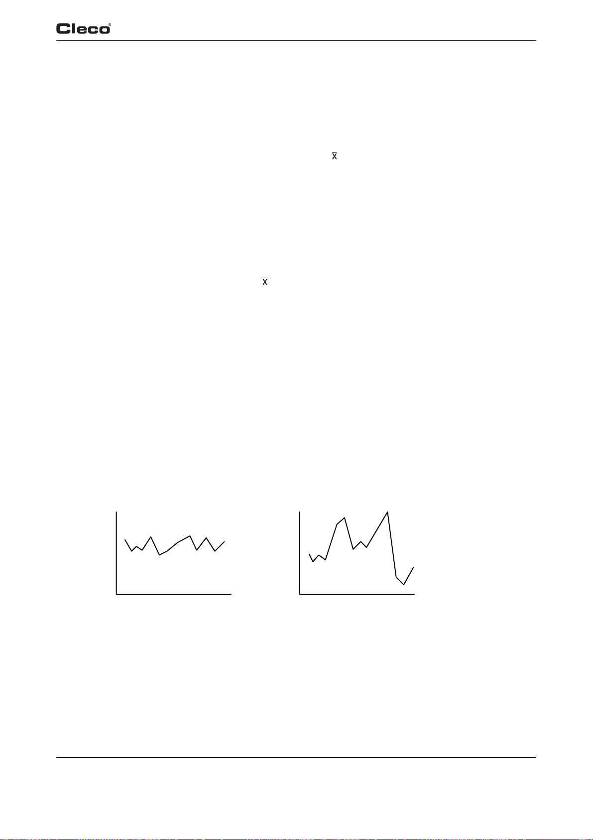
5Statistics
5.1 Understanding Statistics
Your unit provides a wide array of statistical and data reports (charts) for the control of manufacturing processes. The following provides a description of the control chart for variables and an
tline of the procedure for its use. Known as the
ou
variables can be used whenever a quality characteristic can
numerical value. When properly used, it can bring substantial improvement in product quality and
a reduction of scrap and rework.
When we control a process, we monitor the variation of
the product. During production, samples from the process are measured. By plotting the results
of these measurements on the control chart, we are able to see if the process is operating in a
stable manner (in a state of statistical control), or if the pattern has been disturbed by an event
that drives the process out of control. In other words, the control chart tells us what the process is
doing - when to take action and when to leave it alone.
Although it is a powerful tool, the
few basic statistical concepts and the us
-R Control Chart is easy to use. Only an understanding of a
Statistics
5
-R chart (pronounced X-bar-R), the chart for
be measured and expressed by a
the characteristics that are important to
e of simple arithmetic is needed.
5.1.1 The Nature of Variation
Variations in measured product are always present because of random fluctuations and inconsistencies in machines, material, and operator perf
alike.
When variation is random and stable, the process is in a state of st
1:page 97). The process has an identity, and its performance
variation is caused by conditions that are inherent to th
run out, bearing clearances, differences in material properties, accuracy of measuring equipment, and operator performance. We call this "common cause" variation.
When variation is sporadic and unstable, the process is out of st
1:page 97). The process loses its identity and is no longer predictable. The unstable pattern is
caused by such events as tool breakage, tool wear,
called "special cause" variation.
Fig. 5-1: a) Common Cause Variation Fig. 5-1: b) Special Cause Variation
ormance. No two items produced are exactly
atistical control (see a) Fig. 5-
is predictable. The stable pattern of
e manufacturing system, such as spindle
atistical control (see b) Fig. 5-
bad material, and operator error. This is
en05c361.fm, 23.04.200 9 P1934E/EN 2009-04 97
Page 98
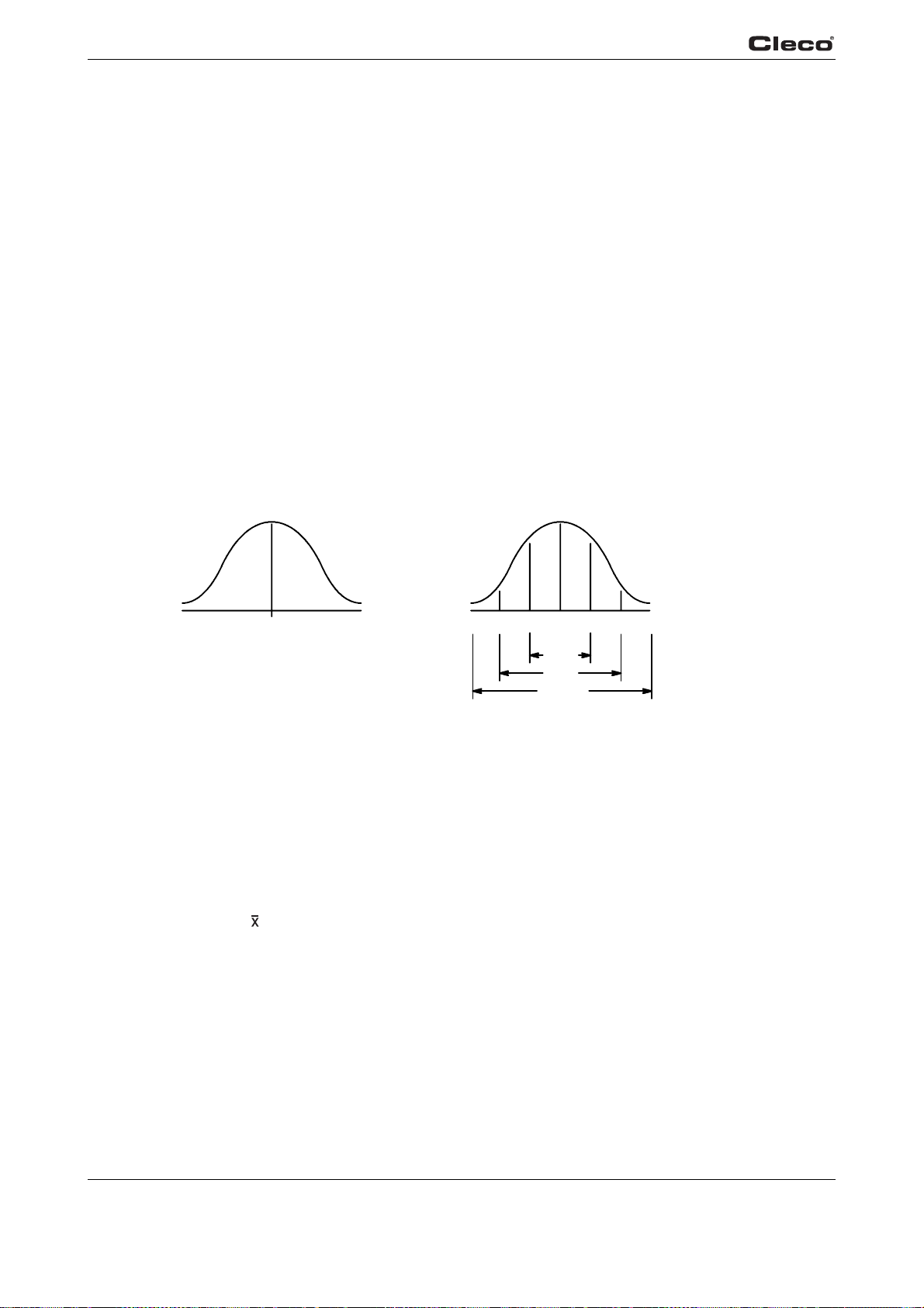
Statistics
5
5.1.2 The Normal Curve
Most processes in statistical control have a fixed pattern of variation. The mathematical curve
that describes this pattern is known as the normal curve (see a) Fig. 5-2:). The normal curve is
symmetrical about the average. It is high in the midd
the average increases. Since the shape resembles a bell, it is sometimes referred to as a bell
curve.
The normal curve is defined by two cond
amount of variation from the average. We can think of these as the center and width of the bell,
respectively. The center is the arithmetic average of all items produced. The width is expressed
in terms of the standard deviation which is a statistical calculation for the amount of variation
from the average. The standard deviation, represented by the Greek letter sigma (σ), holds a
fixed relationship to the normal curve, as follows (see b) Fig. 5-2:):
• 68% of all items produced will
• 95% will be within +2σ of th
• 99.7% will be within +3σ of the aver
le and becomes smaller as the distance from
itions - the average of all items produced, and the
be within
e average (four sigma spread).
+1σ of the average (two sigma spread).
age (six sigma spread).
These two characteristics - the average and the stan
statistical process control. By taking sample measurements during production, we can predict the
average value and the amount of variation for all items produced.
Avg.
Fig. 5-2: a) The Normal Curve Fig. 5-2: b) Areas Under The Normal Curve
5.1.3 The Procedure
The procedure for establishing a statistical process control program consists of three phases.
The first is to obtain statistical control - a state of random and stable variation. The second is to
establish process capability. A state of statistical control in itself does not assure that the process
is capable of meeting the specification. The limits of variation must be equal to or less than the
total specification tolerance. The third is to monitor the process throughout production using the
control chart, to detect and correct conditions that upset the stable pattern of variation.
Use of the
-R Control Chart includes the following steps:
dard deviation - provide the foundation for
1σ1σ2σ 2σ 3σ3σ
Avg.
68%
95%
99.7%
1. Select the Characteristic
Since a separate chart is required for each characteristic, pr
selected requirements. A good candidate is a characteristic that is important to the function of the
item. Others include those that are causing a high cost loss because of scrap or rework, and
those that require evaluation by destructive testing.
98 P1934E/EN 2009-04 en05c361.fm, 23.04.2009
actical considerations limit use to
Page 99

Statistics
R
A
2. Designate the Sample Size
It is usually desirable to keep the sample size small so that
variation within the sample is at a
minimum, but not so small that statistical validity is lost. The control chart described in this document is structured for a sample size of five units. If a
ufacturing or quality engineer can provide alternate fa
sample other than five is selected, the man-
ctors for use in calculating the control limits
and standard deviation (Steps 8 and 10).
3. Designate the Sample Frequency
n
Selection of the sample frequency should be based o
economic considerations for the cost of
measurements and the potential loss that may occur if samples are not taken often enough.
Early in the production run, samples should be taken more frequently and then extended after
satisfactory control is verified. The frequency may be expressed as a time interval or as a portion
of quantities produced.
4. Assure Measurement Accuracy
tistical control. Measuring and test equip-
Measurement accuracy is mandatory for successful st
ment must be of a type suitable for the characteri
a
stic being evaluated, and must be calibrated
and properly used. Decisions resulting from the analysis of a control chart will be no better than
the measurement data.
5
5. Complete the Data Sheet Headings
a
It is important that all heading entries on the dat
sheet be completed. They include the part
number and description, the operation performed, the name of the operator, the machine or
equipment used, and the specification limits. The data sheet and control chart can provide evi-
gan
dence of quality for use by the Quality Assurance or
ization if the information is properly
recorded and traceable to the products manufactured.
6. Start Production
it
Take samples of five units (preferably consecutive un
s produced) at the designated frequency,
and record each measurement (X) on the data sheet. For each sample of five calculate the aver-
) and range (R), and plot the results on the chart (see Fig. 5-3:).
age (
20
16
verage
12
8
4
ange
0
Fig. 5-3: Entries for Range and Average
X
R
- Add the five measurements and divide the sum by five.
For a sample of five, it is often easier to multiply the sum
by two and move the decimal one place to the left.
R - Substract the smallest measurement from the largest.
(Note that the range can never be negative.)
en05c361.fm, 23.04.200 9 P1934E/EN 2009-04 99
Page 100
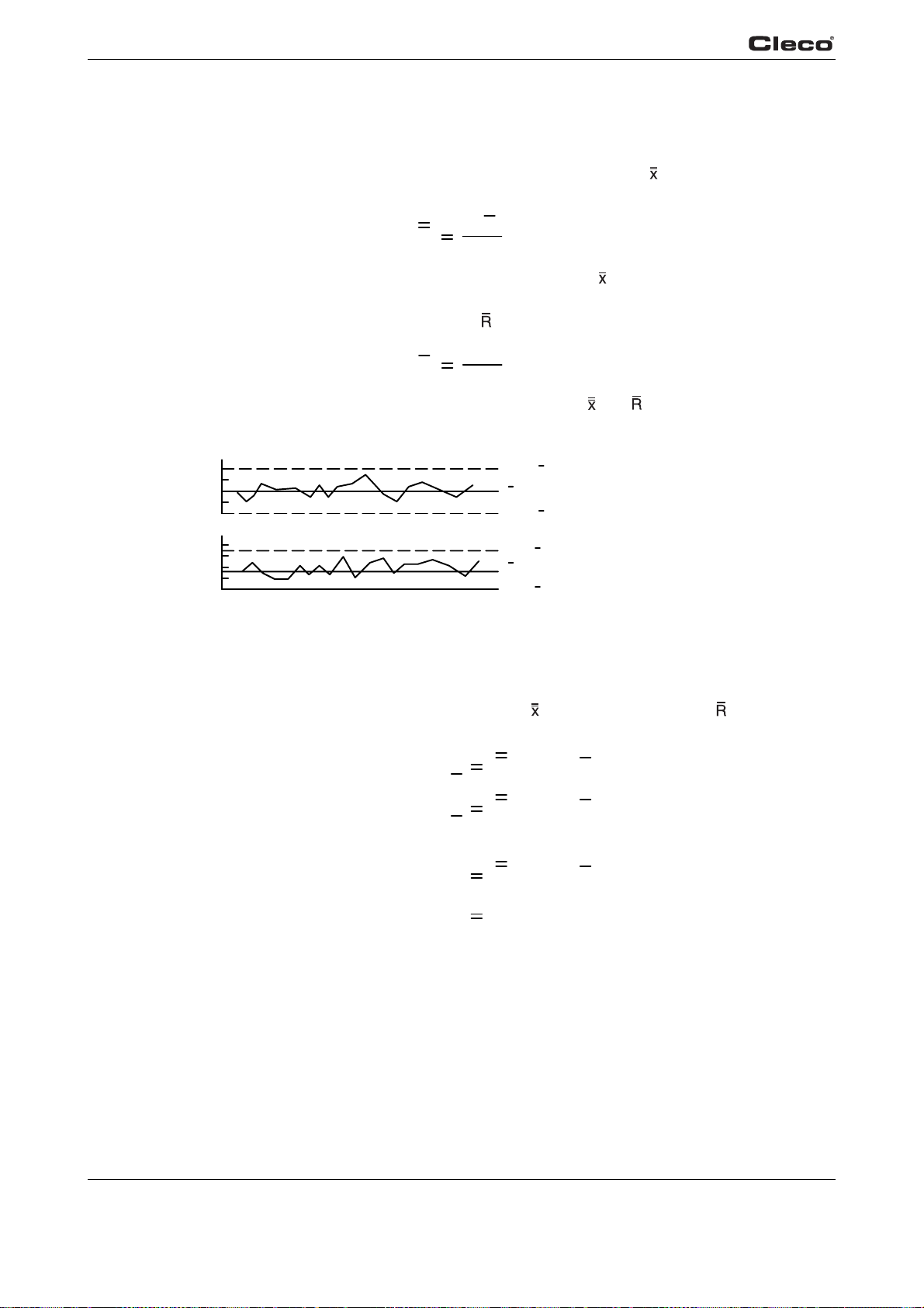
5
R
A
A
Statistics
7. Calculate Process Center Lines
After data for 20 samples of five have been plotted, calculate the center lines for both the average and range plottings.
The center line for the average chart is known as the grand average (
of the sample averages. This is the value that be
X
st represents the size of all measurements:
Σ
X
n
) and is the average of all
where Σ is used to indicate the sum of the sample averages, ( ), (be careful to observe the
+ and - signs), and n the number of samples, in this case 20.
Similarly, the center line for the range chart (
R
Draw solid lines on the control chart for values representing and (see Fig. 5-4:).
20
16
verage
12
8
4
ange
0
Fig. 5-4: Drawing The Center Lines And Control Limits
8. Calculate Control Limits
Calculate the upper and lower control limits (UCL and LCL) using the following formulas and the
values pr
for samples of five units only.)
eviously calculated for the grand average (
) is the average of the ranges for all samples.
Σ
R
n
UCL
X
X
LCL
X
UCL
R
R
LCL
R
) and the average range ( ). (Factors are
+0.577(R)
verage
UCL
LCL
X
x
0.577(R)
X
x
+2.114(R)
Range
UCL
LCL
Note: For a sample size of six or less, the lower control limit for the range is zero.
Plot the limits on the control chart as broken lines.
9. Evaluate for Statistical Control
Analyze the control chart to see if the process is in a state of statistical control. Variation should
random about the center lines for both averages and ranges, with all points within the control
be
limits. If these conditions are not satisfied, special cause variation may be present.
100 P1934E/EN 2009-04 en05c361.fm, 23.04.2009
X
R
0
R
 Loading...