

ClearSpan Tall Boy Moo-Tel Instruction Manual
ClearSpan™
Tall Boy Moo-Tel™
©2010 ClearSpan™
All Rights Reserved. Reproduction
is prohibited without permission.
Revision date: 02.10.10
Photo may show a different but similar model.
STK# DIMENSIONS
R030 30' W x L (length varies)
R035 35' W x L (length varies)
1

Table of Contents
Important Information ..............................................3
Parts Identification ...................................................7
Overview....................................................................8
Prepare and Square the Building Site ....................9
Set the Ground Posts (option) ................................10
Mounting Feet (option) .............................................12
Rafter Assembly .......................................................13
Frame Assembly .......................................................14
Baseboard Installation .............................................18
Cable Installation ......................................................19
Diagonal Strut Installation .......................................21
Mounting Foot-to-Rafter Strut Installation .............22
Optional Support Package Installation (Rafter) .....23
Anchor the Assembled Frame .................................25
Corner Cap Installation ............................................26
Frame Check .............................................................27
Ribbon Board Installation ........................................28
Attach Side Ratchets................................................29
Roll-Up Sides Installation ........................................30
Drop-Down Sides Installation ..................................32
Main Cover Installation ............................................40
Install Twist-of-the-Wrist Assembly ........................46
Shelter Care and Maintenance ................................48
Quick Start Guide .....................................................49
30' Wide Front Profile Grid w/ Ground Posts ..50
30' Wide Front Profile Grid w/ Mounting Feet .51
35' Wide Front Profile Grid w/ Ground Posts ..52
35' Wide Front Profile Grid w/ Mounting Feet .53
Front Profile with Ground Posts .......................54
Front Profile with Rafter Feet ............................55
Purlin Locations .................................................56
Side Profile - 20' Length ....................................57
Side Profile - 30' Length ....................................58
Side Profile - 36' Length ....................................59
Side Profile - 40' Length ....................................60
Side Profile - 48' Length ....................................61
Side Profile - Longer than 48' ...........................62
Connections with Ground Posts ......................63
Connection Details - Ground Posts ................64
Connections with Rafter Feet ...........................65
Connection Details - Rafter Feet ......................66
Mounting Feet Layout ........................................67
30' Wide Over-The-Top Measurements ............68
35' Wide Over-The-Top Measurements ............69
30' Rafter Profile with Optional Support Bracing
(R030A0015) .......................................................70
35' Rafter Profile with Optional Support Bracing
(R035A0015) .......................................................71
READ THIS BEFORE YOU BEGIN
The main building and any accessory (end wall, door, etc.)
requires a specific installation sequence. All buildings
include an instruction guide; each accessory includes an
instruction guide.
Near the beginning of each instruction guide (building or
accessory), you will find information to lead you through
the installation and assembly steps. This information
identifies at what point during the assembly a particular
accessory is installed or attached to the main building
frame. In all instances and regardless of the type and
number of accessories, the main building frame is
always constructed first.
Since we cannot anticipate changes made by the
customer/contractor, all instructions assume the use of
accessories purchased from us to be used on the building
the accessory was designed for. Each instruction guide
presents the basic steps to install the accessory. When
in doubt, consult the services of a qualified contractor
experienced with the assembly of similar structures.
Assemble the main building frame now.
IMPORTANT: After assembling the frame, choose one of
the following procedures to continue:
12.5 oz. Cover Installation with Drop-Down Sides•
12.5 oz. Cover Installation with Roll-Up Sides•
Consult the Table of Contents for the page that each
procedure begins. To confirm what feature (drop-down
or roll-up) you have ordered with your building, complete
these steps (if needed):
Go to http://www.farmtek.com and type the sku 1.
number of your building into the Catalog Item # field
near the upper left of the Home Page window.
Verify that you have typed the correct sku # in the 2.
field (e.g., R030036P01TB02W).
Click Go to view the building description for the sku # 3.
you have entered.
Mounting Feet (108500) Layout Diagram
Buildings equipped with the 108500 mounting feet require
additional steps for the site preparation. Consult the
Mounting Feet Layout diagram in the Quick Start section
near the back of this guide for the required dimensions.
Do not prepare the site without first consulting the
diagram for the proper dimensions!
Buildings that include "P01" within the building
identification number (e.g., R030020P01FC01W) are
equipped with the 108500 mounting feet.
For buildings with ground posts, consult the Front Profile
with Ground Post diagram in the Quick Start section to
properly prepare the site.
Buildings that include "GP1" within the building
identification number (e.g., R030020GP1FC01W) are
equipped with ground posts.
2
Revision date: 02.10.10

Important Information
YOU MUST READ THIS DOCUMENT BEFORE YOU
BEGIN TO ASSEMBLE THE SHELTER.
Thank you for purchasing this ClearSpan™ Tall Boy
Moo-Tel™. When properly assembled and maintained,
this product will provide years of reliable service. These
instructions include helpful hints and important information
needed to safely assemble and properly maintain the
shelter. Please read these instructions before you begin.
If you have any questions during the assembly, contact
Customer Service for assistance.
LOCATION
Choosing the proper location is an important step before
you begin to assemble the structure.
The following suggestions and precautions will help you
determine whether your selected location is the best
location.
Never erect the structure under power lines.•
Identify whether underground cables and pipes are •
present before preparing the site, setting ground
posts (if equipped), or anchoring the structure.
Location should be away from structures that could •
cause snow to drift on or around the building.
Do not position the structure where large loads •
such as snow and ice, large tree branches, or other
overhead obstacles could fall.
SAFETY PRECAUTIONS
Wear eye protection.•
Wear head protection.•
Wear gloves when handling metal parts.•
Use a portable GFCI (Ground Fault Circuit Interrupter) •
when working with power tools and cords.
Do not climb on the frame during or after construction.•
Do not occupy the structure during high winds, •
tornadoes, or hurricanes.
Provide adequate ventilation if the structure is •
enclosed.
Do not store hazardous materials in the structure.•
Provide proper ingress and egress to prevent •
entrapment.
Always check local building codes before you begin •
and follow codes as instructed.
SITE
After choosing a location, proper preparation of the site is
essential. Follow the information below.
A level site is required• . The site must be level to
properly and safely erect and anchor the structure.
If the site is not level, use footings to provide a secure •
base to assemble the structure. Pre-cast concrete
blocks, pressure-treated wood posts, or poured
footings are all acceptable when properly used.
(Some shelters use ground posts or rafter feet.)
Drainage: Water draining off the structure and from •
areas surrounding the site should drain away from the
site to prevent damage to the site, the structure, and
contents of the structure.
WARNING: The individuals assembling this structure
are responsible for designing and furnishing all
temporary bracing, shoring and support needed
during the assembly process. For safety reasons,
those who are not familiar with recognized
construction methods and techniques must seek the
help of a qualified contractor.
Revision date: 02.10.10
3

Important Information
ASSEMBLY PROCEDURE
Following the instructions as presented will help ensure
the proper assembly of your structure. Failing to follow
these steps may result in an improperly assembled
and anchored structure and will void all warranty and
protection the owner is entitled.
The steps outlining the assembly process are as follows:
Verify that all parts are included in the shipment. 1.
Notify Customer Service for questions or concerns.
Read these instructions, and all additional 2.
documentation included with the shipment before you
begin assembling the structure.
Gather the tools, bracing, ladders (or lifts), and 3.
assistants needed to assemble the structure.
Check the weather 4. before you install the roof cover
and any panels (if equipped). Do not install covers or
panels on a windy or stormy day.
Re-evaluate the location and site based on the 5.
information and precautions presented in the
documentation included with the shipment.
Prepare the site (if applicable).6.
Assemble the frame components in the order they are 7.
presented in these instructions.
Assemble the frame including the struts (if equipped). 8.
Consult the 9. MUST READ document and properly
anchor the assembled frame.
Install, tighten, and secure the end panel and main 10.
cover (if equipped). This applies to covers that stretch
over the frame assembly. Your shelter may include
roof panels or side panels or both.
Read the care and maintenance information at the 11.
end of these instructions.
Complete and return all warranty information as 12.
instructed.
Conduit:• An assembly of pipes used to secure the
main cover and end panels (if equipped). Purlins and
some strut assemblies also consist of connected pipes
to form a conduit. Each pipe joint of a conduit
assembly is secured with a self-tapping Tek screw.
Coupler or Fitting:• A part of the frame assembly
where legs, purlins and rafter pipes are inserted and
secured. In most instances, 3-way and 4-way couplers
are used. In some larger applications, couplers are
used to secure the joints of the different rafter sections
during the assembly of the rafters. Some shelters do
not use couplers.
Foot or Rafter Foot:• The part attached to and found
at the base of the rafter or leg of the shelter.
Depending on the shelter, the foot is an optional
purchase. Some shelters do not offer an optional foot.
Some use 1-way connectors or ground posts.
Must Read Document:• This document includes
building and shelter anchoring instructions, steps
for end wall reinforcement, safety precautions, and
notices and warnings. The Must Read document is
sent with all shelters and buildings. If you did not
receive a Must Read document, contact Customer
Service to request one.
On-Center:• Term used to describe a measurement
taken from the vertical center of the rafter or frame
member to the vertical center of another.
Purlin:• The pipe assembly that runs perpendicular to
the rafters or framework that supports the main cover.
Purlins are found on the sides and roof areas of the
assembled frame, are evenly spaced, and typically run
from the front to the back of the shelter.
Plain or Straight Pipe:• A term used to describe a
pipe that has the same diameter or width throughout
its entire length.
Strut:• A strut is usually a length of pipe with two
flattened ends and is used for diagonal bracing of the
shelter frame. A strut is typically secured to the frame
work by special brackets and bolts.
LIST OF WORDS AND PHRASES
Before you begin, it is important to become familiar with
the words and phrases used in this instruction manual.
These words and phrases are common to most
ClearSpan™ shelters and identify the different parts of
the shelter. (Some are used in this document. Others may
not apply to this particular shelter.) These terms describe
the shipped parts and can also be found on the materials
list/spec sheets included with the shipment. To aid in the
assembly, read through the following definitions before
you begin to assemble your shelter.
4
Swaged End or Swaged Pipe:• The term “swaged''
refers to the tapered end of the pipe or tube. Swaged
ends of a pipe can be inserted into couplers and the
straight ends of other pipes.
Tek Screw:• A self-tapping fastener used to secure
pipe joints and to fasten brackets to rafters.
Revision date: 02.10.10

REQUIRED TOOLS
Important Information
The following list identifies the main tools needed to
assemble the shelter. Additional tools and supports may
be needed depending on the structure, location, and
application.
Tape measure or measuring device•
Marker to mark locations on the pipes and rafters•
Variable speed drill and impact driver (cordless with •
extra batteries works best)
Metal-cutting saw or tool to cut cable•
Wrenches and impact socket set•
Scissors, utility knife, or tin snips•
Hammers and gloves•
Adjustable pliers and self-locking pliers•
Ladders, work platforms, and other machinery for •
lifting designed to work safely at the height of the
building
UNPACK AND IDENTIFY PARTS
Space below is reserved for customer notes.
The following steps will ensure that you have all the
necessary parts before you begin to assemble the shelter
frame.
Unpack the contents of the shipment and place where 1.
you can easily inventory the parts. Refer to the Bill of
Materials/Spec Sheets.
Verify that all parts listed on the Bill of Materials/Spec 2.
Sheets are present. If anything is missing or you have
questions, consult the Pictorial Parts Guide and all
diagrams for clarification, or contact Customer
Service.
NOTE: At this time, you do not need to open the
plastic bags containing smaller parts such as
fasteners or washers (if equipped).
Revision date: 02.10.10
5
Important Information
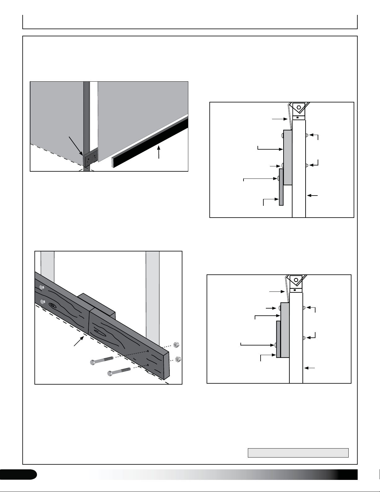
BASEBOARD NOTE
A customer-supplied baseboard and retaining board
are required to attach the drop-down and roll-up side
panels. The baseboard is optional but recommended for a
building with a roll-up side. See the exploded view below.
Optional
End Panel
Baseboard
Ground Level
Drop-Down
Panel
Retaining Board
View shown from outside the shelter.
The baseboard runs the length of the frame at ground
level. The retaining board secures the drop-down panel
to the baseboard. The baseboard and retaining board are
supplied by the customer.
Retaining boards are attached during the drop-down
and roll-up panel installation. The retaining board for the
drop-down panel attaches to the baseboard; the retaining
board for the roll-up panel attaches to the ribbon board.
Secure baseboard and ribbon
board joints between rafters
as shown for best results.
RIBBON BOARD REQUIRED: DROP-DOWN SIDES
A customer-supplied two-piece ribbon board is required
for the installation of the drop-down panel. Consult the
Drop-Down Sides procedure for details regarding the
installation of a two-piece ribbon board. Fasteners are
included. Customer supplies the materials for the ribbon
board.
End View
Corner Cap
2" x 6" Ribbon Board
5/16" x 5"
Carriage
Bolts
FA4652 Wood
Grip Screw
Retaining Board
5/16" Nuts
(FALB32B)
Rafter Leg
or Ground
Post
RIBBON BOARD REQUIRED: ROLL-UP SIDES
A customer-supplied ribbon board and retaining board
are required for the installation of the roll-up panel.
Consult the Roll-Up Sides procedure for details regarding
the installation of these items. Fasteners are included.
End View
Inside of
Shelter
Ground
Level
Outside of
Shelter
Fasteners (5/16" x 5" carriage bolts and FA4652 wood
screws) are included. Depending on board width, use 2
carriage bolts per rafter connection for the baseboard
and ribbon board. Evenly space the wood screws at 24".
Countersink heads if needed.
ATTENTION: A baseboard is not required for buildings with
a roll-up side panel, but installing a baseboard is strongly
recommended. Fasteners are included to attach the boards
to the frame.
Corner Cap
5/16" x 5"
Carriage
Bolts
2" x 6" Ribbon Board
FA4652 Wood
Grip Screw
Retaining Board
5/16" Nuts
(FALB32B)
Rafter Leg
or Ground
Post
Customer supplies the materials for the ribbon board and
retaining board.
DIAGRAMS ARE NOT TO SCALE.
6
Revision date: 02.10.10

Parts Identification
The following graphics and photos will help you identify
the different parts. (Some parts are not shown.)
AS5020 Pulley
103544
Mounting Plate
103496
Gearbox
FA4482B
& FA4484B
Tek Screw
FAG402B
1/2" x 2-1/2" Hex Bolt
FAG361B
3/8" x 2-1/2" Hex Bolt
102921 Neo-
bonded Washer
QH1061
1" Ratchet
FAME09B
1/2" Flat washer
FAME08B
3/8" Flat washer
FALB08B
1/2" Locknut
FALB04B
3/8" Nut
QH1065
2" Ratchet
FAG365B
3/8" x 3-1/2" Hex Bolt
AS1003
Cable Clamp
104189 Turnbuckle
108553
Wafer Head
Screw
AS1083
3/16" Cable
Thimble
102570
Aluminum
Channel (roll-
up sides)
FAG330B
5/16" x 1" Hex Bolt
FAG304B
1/4" x 1" Hex Bolt
Revision date: 02.10.10
FAME07B
5/16" Flat washer
FALB01B
1/4" Zinc Nut
FALF37B
5/16" Locknut
CFG030PINSS01
Splice
FAG340B
5/16" x 3-1/2" Hex Bolt
108500
Mounting Foot
(not used with ground posts)
109023
Repair Tape
108503
Cable Bracket
7

Overview
ClearSpan™
Tall Boy Moo-Tel™
OVERVIEW
This section describes assembling your shelter. See
illustration below to identify main parts of the shelter.
Set the ground posts or mounting feet (if equipped).1.
Locate the required parts for each assembly 2.
procedure.
Assemble the rafters and frame.3.
Anchor the frame. Consult instructions for details.4.
Attach panels (if equipped), and roll-up or drop-down 5.
sides. (Additional purchase required for end panels.)
Attach main cover.6.
Drawing may show a model of a different length. Refer to
Quick Start section located in the back of these instructions
for on-center measurements and post layout.
Interior Rafter
Ridge Purlin
End Rafter
Under Purlin
Cable
Ground
Post
Corner
Customer-Supplied
Baseboards
Strut
Ground Level
8
Cap
On-center
Revision date: 02.10.10
Prepare and Square the Building Site
PREPARE THE BUILDING SITE
A level site is required to accurately and safely construct
the building. Consult the services of a qualified contractor
to properly grade and prepare the site.
Site should slope away from the building to allow water to
properly drain away from the assembled building.
After the site is prepared, mark the location of the frame
corners to square the frame during assembly. Taking
these steps before assembling the shelter saves time and
ensures that the structure is square and positioned as
desired.
The following procedures are suggested methods.
Their use depends on the size of the shelter, shelter
application, the footings (if applicable), and the method
used to anchor the shelter.
When in doubt, consult the services of a qualified
contractor experienced with the construction of similar
structures.
Rafter Mounting Feet
If your frame includes mounting feet, prepare the site and
anchor the feet to the site before assembling the frame.
Use a baseboard placed under the feet to support the foot
base. Read the information on the next page and use the
diagram to layout the position of your building. Once the
string lines are set to mark the location, continue with the
Mounting Feet section.
SQUARE THE SITE: GENERAL STEPS
Identify a corner where a building rafter will be 1.
positioned, drive in a stake, and string a line the exact
width of the building and stake in place. (Width of the
rafter is measured from center-to-center of the rafter
legs.)
After the first corner stake is in place, string a line the 2.
width of the building (center-to-center) and drive the
second corner stake into the ground.
String a line at least as long as the building 90° from 3.
the line between the first and second stakes.
Do not dig holes if your building is equipped with rafter
mounting feet!
Ground Posts
If the frame includes ground posts, set all ground posts
as described within this manual. Width of the shelter
is measured from the center of one ground post to the
center of the remaining ground post. Length is also
measured center-to-center. If your building includes
ground posts, continue with the Setting Ground Post
section.
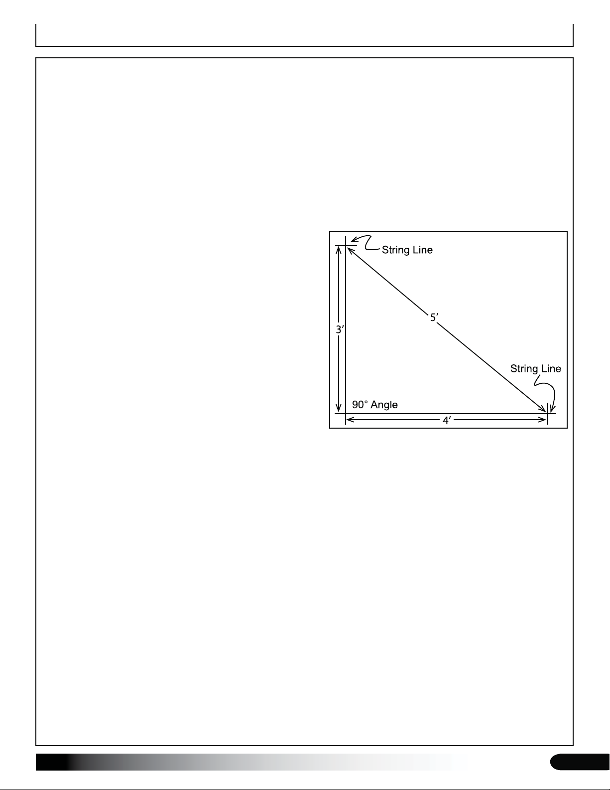
NOTE: A transit can be used to ensure an accurate
90° angle, or the 3-4-5 rule can be used. Refer to
diagram. Using multiples of 3-4-5 such as 6-8-10 or
12-16-20 helps to maintain an accurate 90° angle.
After squaring the position of the building, measure 4.
the length and drive the third corner stake.
Repeat the same step for the last corner stake. 5.
NOTE: The distance measured diagonally between
corner stakes must be equal for the building to be
square.
Revision date: 02.10.10
9
Set the Ground Posts (option)
MARK THE SITE AND DIG POST HOLES
These steps describe marking all post hole locations and digging
the holes. For some sites, it may not be possible to complete the
procedure in this manner. An alternative procedure such as working
from one end of the building toward the other may be necessary.
Determine the best procedure based on the site and other factors
and proceed as needed.
NOTE: Refer to the Quick Start Section located near the back
of these instructions for the Side Profile and related diagrams.
If your building includes mounting feet, complete Step 1 only
of this procedure and continue with the Mounting Feet section.
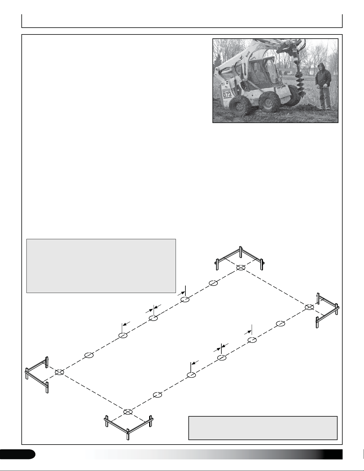
Stake the outline of the building using string line and batter boards. Set batter boards 3' back from the building 1.
corners. Check to ensure that the building layout is square. Cover or panels (if equipped) will not install properly if
the building frame is not square once assembled. (For buildings equipped with rafter mounting feet, stop here and
continue with the Mounting Feet section.)
Consult the diagrams in the Quick Start section to verify the frame length and width dimensions and to accurately 2.
position the ground posts.
Guided by the string line, use a flag or stake to mark each ground post hole location.3.
Move the string line and dig a post hole a minimum of two feet (2') deep or to a depth that is below the geographic 4.
frost line. Consult local building codes. A power auger (8"-12") works best to dig the holes.
After digging all holes, reattach the string line to the batter boards and use it as a guide to set and align the 5.
ground posts.
ATTENTION: Set another string line (not shown) to mark the
uniform height of all main frame ground posts. All posts must
be set at the same height for the frame to assemble properly.
Side wall height–the height of the sidewall from finished
ground level to the top of the ground post–is 72".
Consult the services of a qualified contractor to accurately
layout and set the ground posts.
on-center
on-center
on-center
on-center
10
Drawing may show layout of a different length. Refer to
Quick Start section located in the back of these instructions
for on-center measurements and post layout for your frame.
Revision date: 02.10.10
Set Ground Posts (option)
SET GROUND POSTS
This procedure describes setting the ground posts in
holes, bracing in place, and adding concrete. If your
building includes mounting feet, skip this procedure and
continue with the installation of the mounting feet.
Required parts and equipment:
Ground post (no mounting feet)•
Equipment to level and brace posts•
NOTE: Concrete (customer-supplied) is required to
secure all ground post in the holes. All posts must be set
at the same height for the frame to assemble properly.
Consult the services of a qualified contractor to properly
set posts.
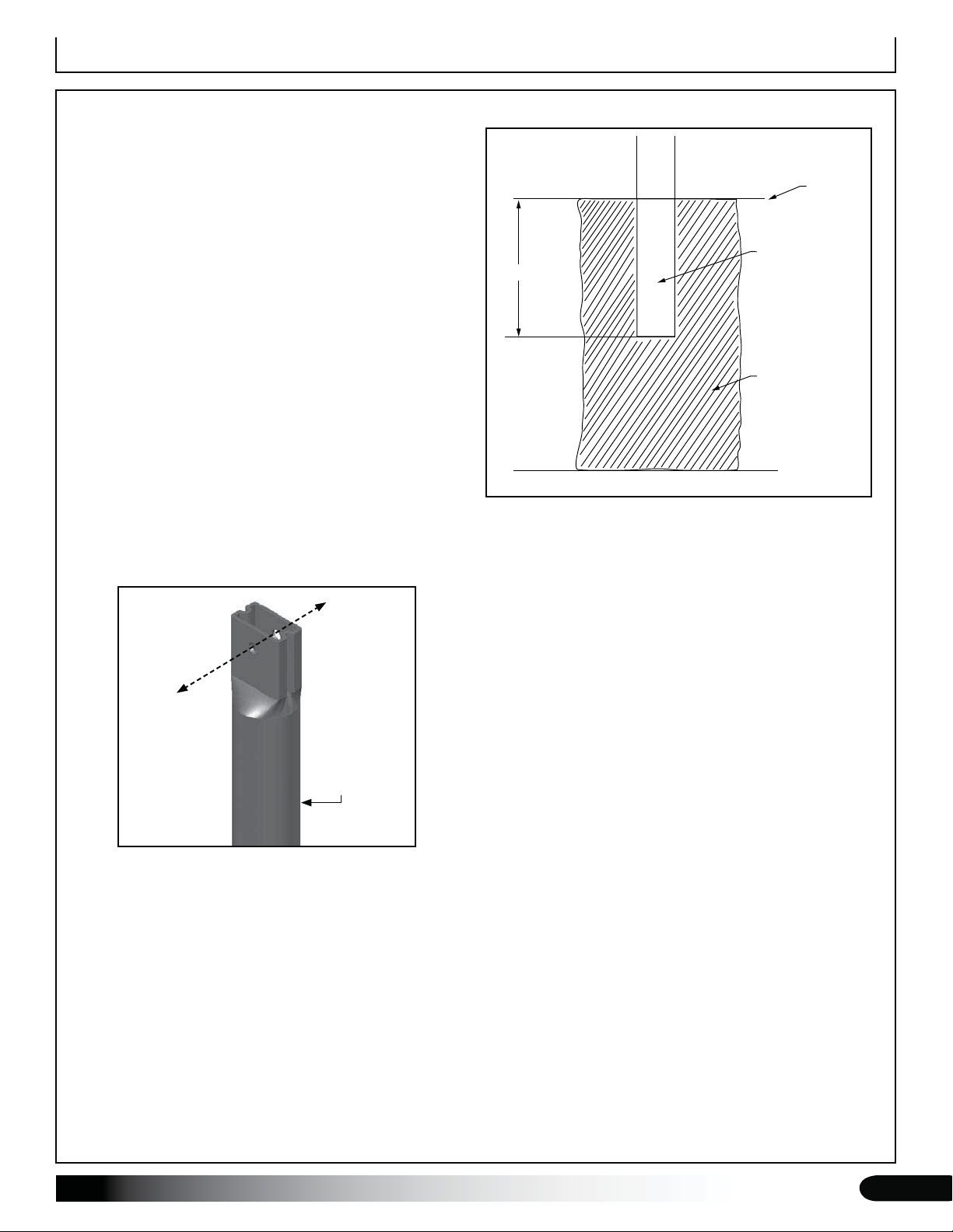
Take one ground post, measure 24" from the plain 1.
end, and mark the location on the pipe. Set all posts
two (2) feet below ground level. See diagram to the
right.
Add concrete to a corner hole, set the first corner 2.
ground post into the hole, and brace in position. Fill
hole so concrete remains below the finished grade.
DIAGRAM SHOWS A TYPICAL POST HOLE
Ground Level
Ground Post
2’ Deep
Concrete
In areas where frost is common, dig each post hole so it
falls below the frost line. Minimum hole depth for all areas
regardless of frost is 24".
Toward
the ends
of the
frame
Toward
the ends
of the
frame
Ground Post
ATTENTION: Position the pre-drilled holes facing
toward the ends of the shelter so they align with the
bolt holes in the rafter sections. Verify that the ground
post is at the correct height.
Check that the corner post is straight (plumb) and 3.
adjust as needed before the concrete sets.
Repeat the above steps to complete the installation of 4.
all ground posts.
Consult local building codes and qualified contractors for
additional details when digging the post holes and setting
the ground posts.
Continue with the rafter assembly.5.
Revision date: 02.10.10
11
Mounting Feet (option)
SETTING THE MOUNTING FEET
In those instances where optional mounting feet have been ordered, secure the feet to a customer-supplied
baseboard prior to attaching the rafter legs and assembling the frame. Customer is responsible for the necessary
baseboards and fasteners used to secure the feet to the site. A baseboard is not needed when the feet are anchored
to a concrete pier, footing, or foundation. Consult the Mounting Feet Layout diagram in the Quick Start section.
ATTENTION: Skip this section if your frame does not include mounting feet.
The following information describes one way to anchor the mounting feet. Consult a knowledgeable construction
professional for suggestions and other safe and acceptable alternatives. Do not assemble the frame without first
securing the mounting feet. Consult the Mounting Feet Layout diagram (Quick Start section) before you begin.
WARNING: Securing the rafter feet to a baseboard as shown does not anchor the shelter. Secure each rafter to
the site after assembly and before attaching the next rafter during the frame assembly steps. Anchor the shelter
as stated in the MUST READ document included with the documentation.
Customer-supplied
baseboards and stakes.
Do not use stake when
setting on concrete.
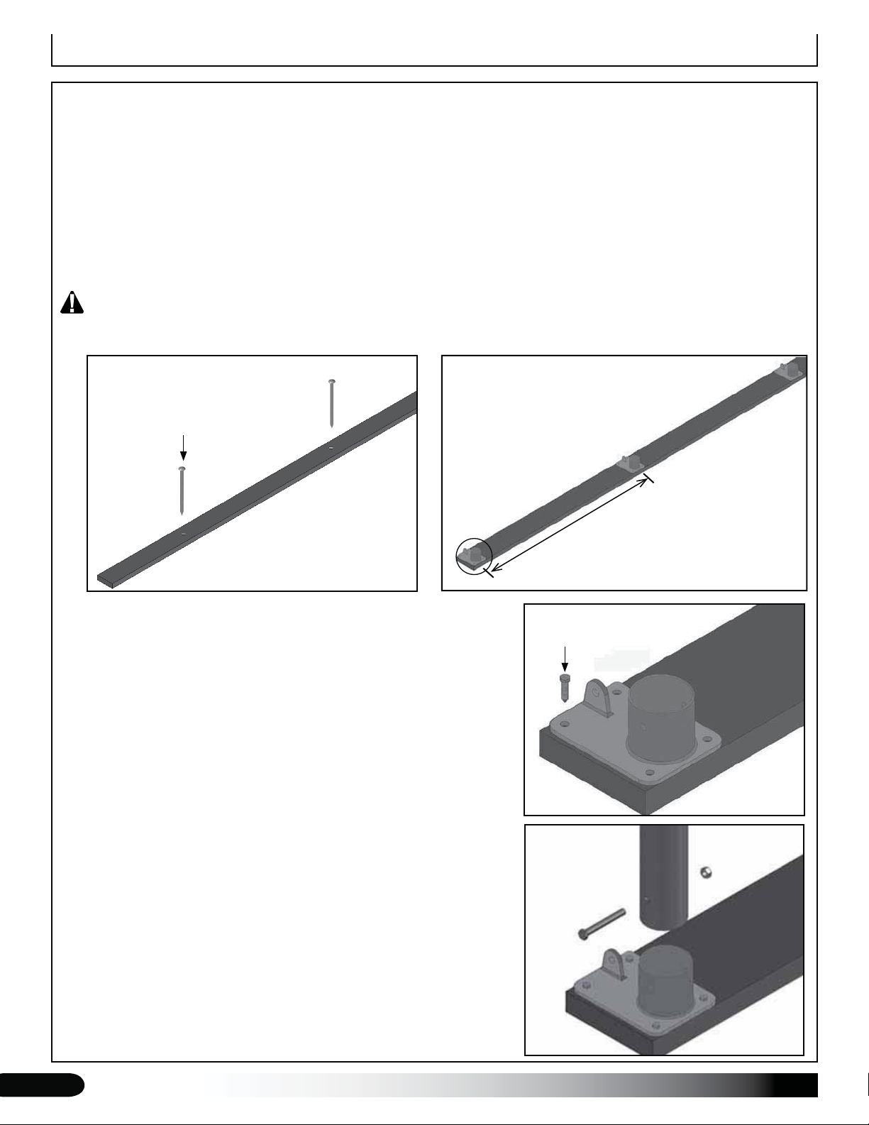
Place the first set of 2" x 8" baseboards on the site at the required 1.
on-center width of the building frame. Baseboards run parallel to
each other. Use the layout instructions to accurately and properly
set the baseboards on the site.
Drive a short length of rebar or similar stake, through a hole 2.
drilled in the boards, into the ground to keep the boards in place.
See diagram above. If mounting on concrete, use wedge anchors
(purchased locally) to secure boards to the site.
NOTE: Rods or stakes will help prevent the boards from shifting
to maintain the on-center width of the building during frame
assembly.
Anchor each mounting foot to the baseboards (on-center) 3.
using the appropriate customer-supplied fasteners. Consult the
diagrams in the Quick Start section for layout dimensions and
details.
Continue with the Rafter Assembly steps that follow. 4.
ATTENTION: The augers for the anchoring system for your
frame can be installed at this time. Consult the ANCHOR THE
ASSEMBLED FRAME section in these instructions for auger
installation suggestions. All anchoring components and hardware
require and additional purchase and are not included. You must
anchor the building as shown in the diagram if mounting feet
are used.
on-center
Customer-supplied
lag screws.
Outside of frame
Secure support
leg to foot before
attaching the
assembled rafter.
See rafter
assembly
steps.
12
Revision date: 02.10.10
Rafter Assembly
RAFTER ASSEMBLY
After setting the ground posts or anchoring the mounting
feet, continue with the rafter assembly.
NOTE: All rafter assemblies consist of two rafter sections
joined by a single splice at the peak. Consult the rafter
diagram in the Quick Start section of these instructions
before and during the rafter assembly process for details.
Assistance is required to assemble the rafters and frame.
Gather the parts:
Rafter sections (30' or 35' wide–2 sections per rafter)•
Rafter splice (#• CFG030PINSS01)
CFG030PINSS01 Spice
3/8" x 2-1/2" bolts, nuts, and flat washers (to secure rafter sections to the splice)•
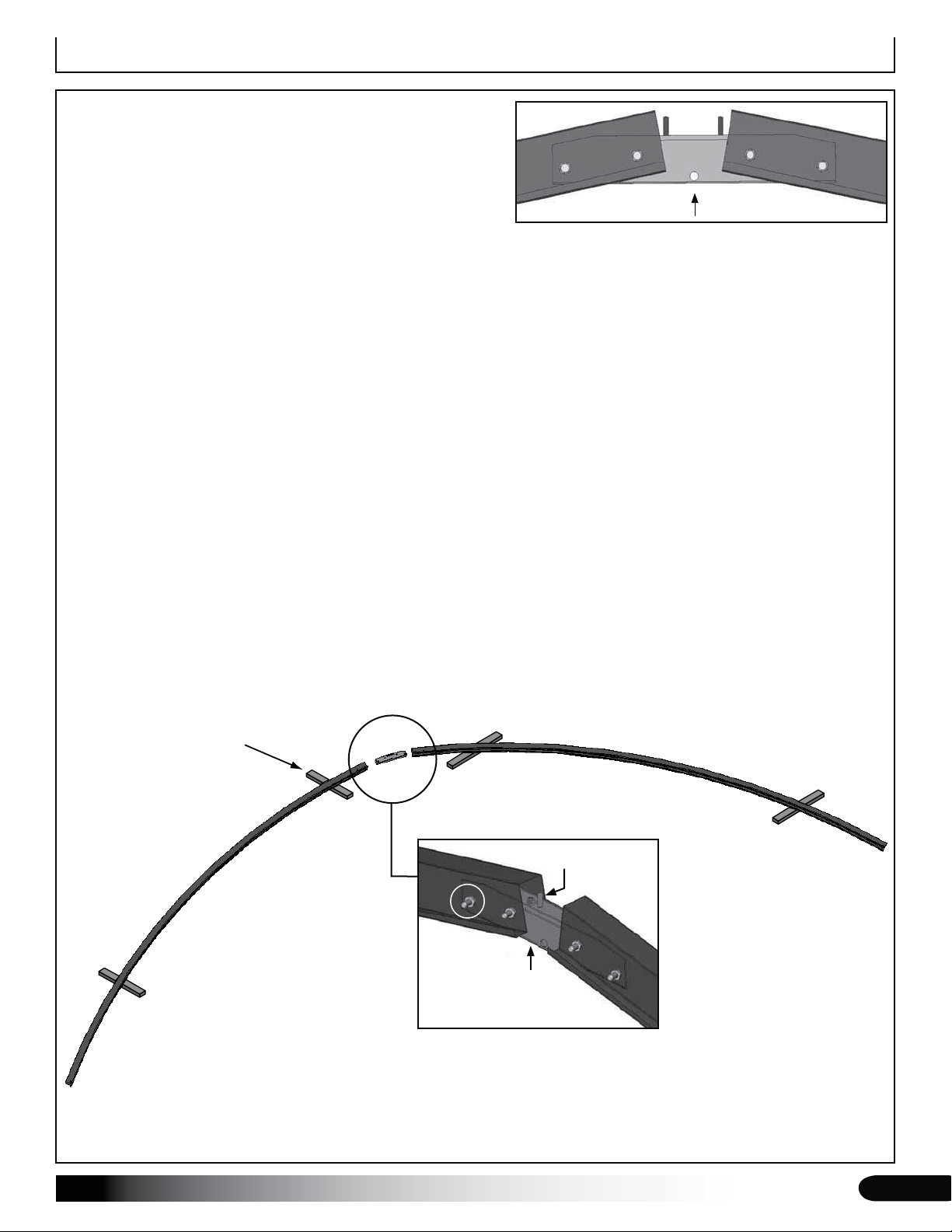
Place two rafter sections on the ground end-to-end. (The end of each section includes the two mounting holes 1.
to secure the splice.) Support the rafter sections with blocks as needed. Consult the diagrams for details.
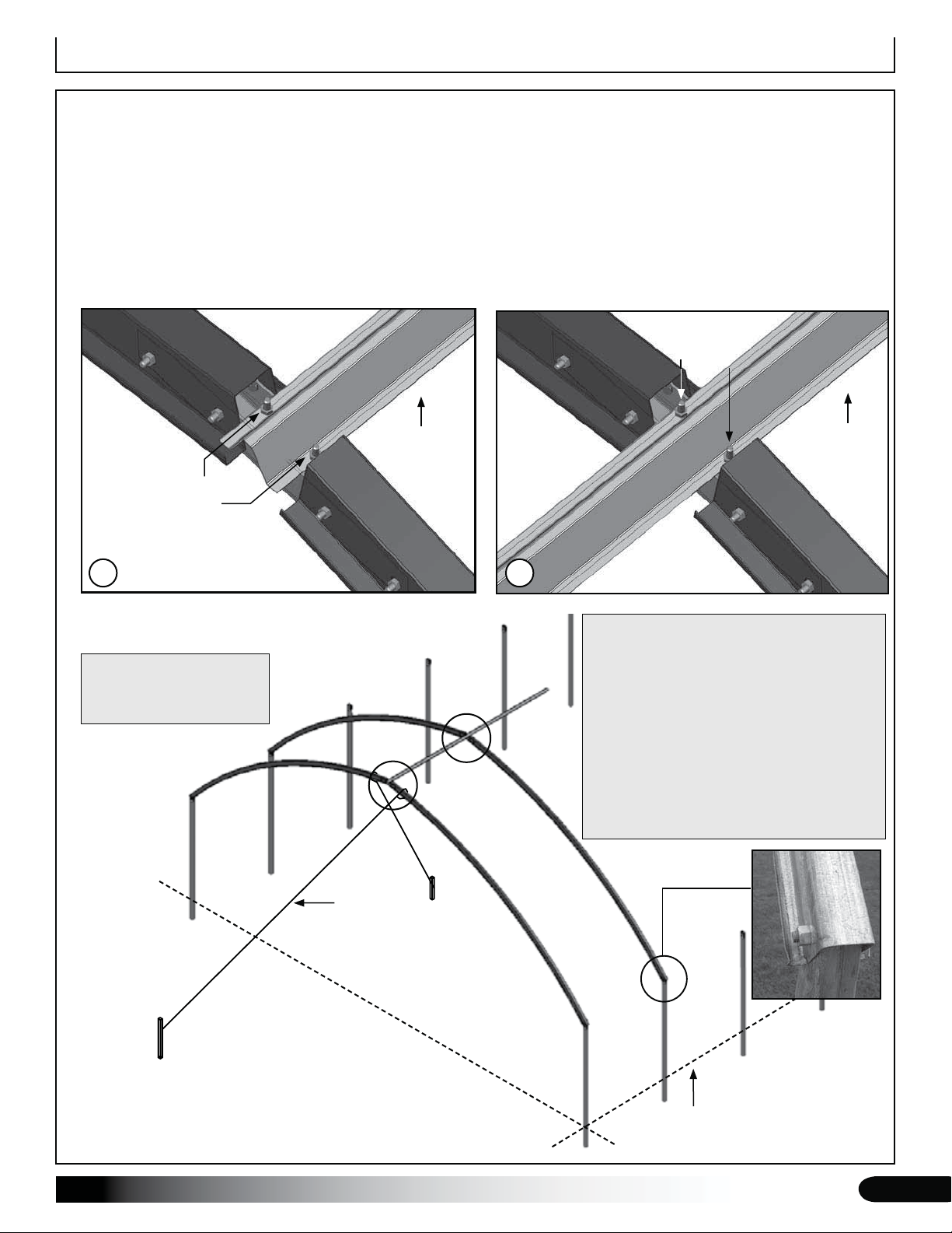
Connect the two rafter sections using a splice, 3/8" x 2-1/2" machine bolts, 3/8" flat washers, and 3/8" nuts. 2.
Position the installed studs of the splice so they point up to accept the top purlins when these are installed. See
the diagram below.
For long frames, it may be best to assemble the individual rafters and set them in place to conserve work
space. To reduce handling, designate assembly areas along the length of the frame and set the individual rafter
sections in those areas to be assembled and connected to the frame.
After assembling some or all of the rafters, continue with the frame assembly. 3.
SUPPORT BLOCKS
Stud
Revision date: 02.10.10
Splice
3/8" x 2 1/2" bolts (FAG361B), 3/8" flat washers
(FAME08B), and 3/8" nuts (FALB04B)
13
Frame Assembly
FRAME ASSEMBLY
Gather the parts:
Assembled rafters and 1/2" x 2 1/2" mounting bolts, nuts, and flat •
washers
Ridge purlins (see Side Profile diagram for your building and for •
purlin identification and correct position) and 1/4" nuts
Under purlins • (see Side Profile diagram for your building for purlin
identification and correct position) with 1/4" x 1" bolts and nuts
108503 angle brackets to mount cables•
108504 eyebolts, 3/8" flat washers, and 3/8" nuts•
Lifts, ladders, assistants, and cable, rope or lumber to secure •
rafters during the assembly process
Complete these steps:
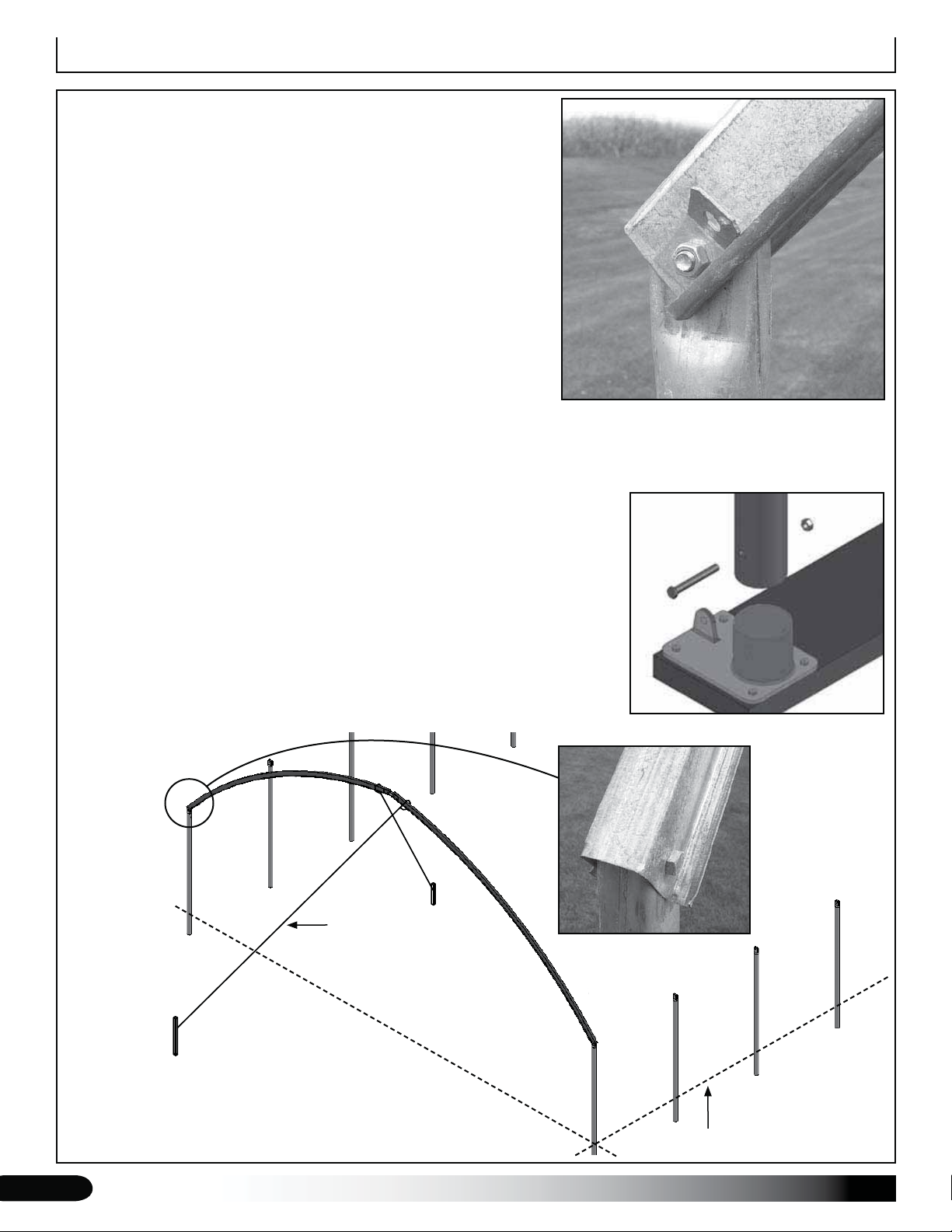
Using ladders and lifts, set an assembled rafter on the first set of ground posts, align the mounting holes, slide a 1.
flat washer onto a 1/2" x 2 1/2" bolt, and insert a bolt into each mounting hole. Position bolt head to the outside of
the frame.
ATTENTION: If mounting feet are used, attach the first set of rafter legs
to the mounted feet and secure with the 3/8" x 3 1/2" bolts and nuts.
Consult the connection diagrams located in the Quick Start section of these
instructions for additional details.
Slide one (1) 108503 angled bracket over each mounting bolt 2. (end rafters
only), add a 1/2" flat washer and nut to each bolt, and tighten. Bracket is to
the inside of the frame and is used later in these instructions to secure the
cable bracing to the frame.
Verify that the end rafter is vertical and not twisted and brace the rafter 3.
using ropes, cables, or lumber staked to the site. Do not remove the end
rafter bracing until the entire frame is assembled.
3/8" Nut
3/8" x 3 1/2"
Bolt
Optional rafter leg with mounting foot.
1/2" x 2-1/2"
Bolt
14
Rope or
Cable
Ground Level
Revision date: 02.10.10
Frame Assembly
FRAME ASSEMBLY (continued)
Move to the next set of ground posts (or mounting feet), attach that rafter (and rafter legs if needed), and brace in 4.
place. As previously described, use the 1/2" bolts to secure the rafter to the tops of the ground posts or rafter legs.
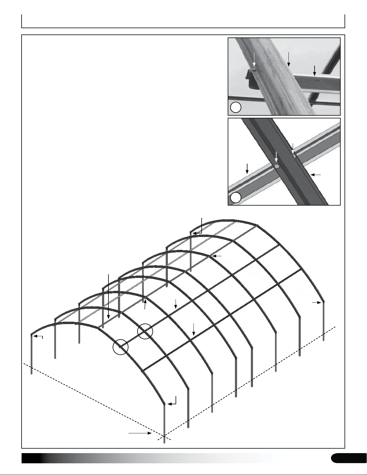
Take the first section of ridge purlin (consult Side Profile diagram for your building length and correct purlin 5.
identification), align the pre-drilled holes with the studs of the rafter splice, and secure to the end rafter (A) and first
interior rafter (B) using 1/4" nuts.
NOTE: If a short purlin spans the first bay, do not secure the purlin to the second rafter until next purlin is added.
Consult the Side Profile diagram for your frame for details.
Splice Studs
1/4" Nuts
A
Example shows a long 12'
purlin in the first bay position.
Different frame lengths may
have a shorter first purlin.
A
Ridge
Purlin
B
Ridge
Purlin
B
NOTE: The 20', 30', and 36' long frames
use a combination of different purlin
lengths during frame assembly.
Consult the Side Profile diagram for your
building length to determine which purlin
to use and where to install that purlin.
Some frame lengths use a 4' or 6' (short)
purlin to span the first bay and to connect
the first two rafters.
Revision date: 02.10.10
Rope or
Cable
Ground Level
15

Frame Assembly
FRAME ASSEMBLY (continued)
Set the next rafter in place, secure it to the ground posts or rafter legs, and brace in place as needed. 6.
Take the next purlin and place the mounting holes over the splice studs and secure with the 1/4" nuts.7.
Take one 108504 eyebolt, FAMA38B lock washer, and a 3/8" nut (FALB04B) and attach the eyebolt to the splice of 8.
the third (3rd) rafter as shown (C). Position the eye of the bolt toward the end rafter for the cable installation.
C
DO NOT secure this end of the ridge
purlin to the rafter at this time. Ridge
purlin is secured to the rafter in the
following steps.
108504 eyebolt, FAMA38B
lock washer, and 3/8" nut
Overlap ridge purlins and secure
in place using 1/4" nuts.
Ridge
Purlin
Diagram above shows how to connect the next purlin at
the same splice. Use one set of 1/4" nuts to secure both
purlins.
16
C
Rope or
Cable
Ground Level
Revision date: 02.10.10
Frame Assembly
FRAME ASSEMBLY (continued)
With the first two bays (3 rafters) assembled, take the 9.
first under purlin and secure it to the rafters using the
1/4" x 1" bolts and 1/4" hex nuts. See diagrams D and
E at the right.
NOTE: The purlin pattern is the same as the ridge
purlin. Consult the Side Profile diagrams for details.
Install and secure the remaining under purlins for the 10.
first bay as previously described and as shown in the
Quick Start section of these instructions.
Repeat the previous steps to assemble the remainder 11.
of the frame.
ATTENTION: Attach the final eyebolt to the splice of
the third (3rd) from the last rafter as described in
Step 8.
When mounting the remaining end rafter, install the
final two (2) angled cable brackets as described in
Steps 1 and 2.
Continue with the installation of the baseboards.12.
(2) 1/4" x 1" bolts
and 1/4" nuts
Purlin
D
(2) 1/4" x 1" bolts
and 1/4" nuts
Purlin
Rafter
E
Cable Bracket
Cable
Bracket
Ridge Purlin
D
Eyebolt
E
Purlin
Cable
Bracket
Eyebolt
Cable
Bracket
Purlin
Revision date: 02.10.10
Ground Level
Frame length of your building may differ from what is shown.
17
Baseboard Installation
BASEBOARD INSTALLATION
Gather the parts:
2" x 6" or 2" x 4" treated or recycled plastic lumber•
(supplied by customer)
5/16" x 5" carriage bolts (FAH325B)•
5/16" nuts (FALB32B)•
The following procedure describes one way to install the
required baseboards. The size and type of the baseboard
you choose may require the use of alternative steps.
When properly installed, baseboard runs the length of the
frame at ground level. The baseboard is supplied by the
customer.
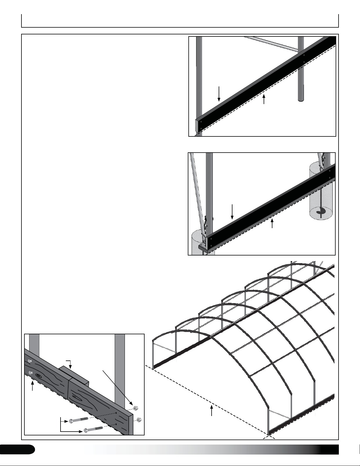
On the outside of the frame, attach the first baseboard
to the rafter using two (2) 5/16" x 5" carriage bolts and
nuts. Countersink heads if needed. Continue adding
baseboards to complete the first run.
Splices are made between posts as shown in the drawing
below. Use a short section of baseboard to secure
separate baseboards at a splice.
Repeat steps to install the second run of baseboards on
the remaining side of the frame.
NOTE: The boards should be at ground level or slightly
into grade to prevent the shelter from sinking and required
to attach the panel's lower edge.
After installing the baseboards, continue with these
instructions.
Baseboard
Ground Level
Ground Posts and Baseboard
Views as seen from the outside. Struts and
anchoring shown are installed in later steps.
Baseboard
Ground Level
Rafter Feet and Baseboard
Ground
Level
Outside of
Shelter
18
Inside of
Shelter
Splice
5/16" x 5"
Carriage Bolts
5/16" Nuts
(FALB32B)
Ground Level
Revision date: 02.10.10
Cable Installation
CABLE ASSEMBLY
Cable assemblies provide diagonal bracing for the building. Each
cable assembly includes the following items:
One (1) length of cable: Measure from point-to-point on the •
frame and cut cable length as needed. Remember to allow
extra to secure the connections and install the clamps.
Turnbuckle (1) and anchor shackle (AS2167) (1)•
Cable thimbles (2) and cable clamps (4) •
Cable Assembly Procedure
Using the diagram below, measure between points A & B, add 1.
12" for connections, and cut two lengths of cable from the
supplied roll to the determined length.
Dead End
Thimble End (Attach thimble end
to the anchor shackle.)
Cable Clamps
Typical Turnbuckle Assembly
Thimble
Thimble
Turnbuckle Jaw
Anchor Shackle
Cable Clamp
Cable
Turnbuckle
Attach turnbuckle jaw to the
cable bracket at the end rafter
connection.
Turnbuckle Jaw
ATTENTION: Always measure before cutting the cable.
B
A
Cable
Measure between Points A & B, add
extra for connections, and cut the
cable to length. All cable sections will
be the same length.
Finish one cable end of each cable (Step 1) using 2.
a thimble and two (2) cable clamps. Use the
diagrams as guides.
Remove the bolt from the anchor shackle and 3.
slide the finished end of each rough cable onto the
shackle. See the diagram at the upper-right corner
of this page.
Secure the anchor shackle to the eyebolt attached 4.
to the peak of the third rafter. See diagrams on the
next page.
Take two turnbuckles and add a thimble to one end of 5.
each. Use adjustable pliers to snap the thimble over
the jaw bolt or remove and reinstall the bolt to add the
thimble.
Open a turnbuckle (Step 5) to its extended/open 6.
position and secure the free end (one without the
thimble) to the cable bracket attached to the end rafter
ground post. (See diagrams on the next page.) Repeat
for the remaining corner of the same end rafter.
Thread the free end of one cable (Step 4) around 7.
the thimble installed in Step 5, pull the cable tight
to remove any slack, and secure the cable to the
turnbuckle using two cable clamps.
Repeat the previous step to attach the remaining 8.
turnbuckle to the free end of the remaining cable.
Check all clamps and bolts of each cable assembly to 9.
ensure they are tight. Trim or tape cable ends.
Repeat the above procedure to install the cables at the 10.
other end of the assembled frame.
With all cables assembled and attached, tighten each 11.
turnbuckle. Do not overtighten.
Revision date: 02.10.10
19
Cable Installation
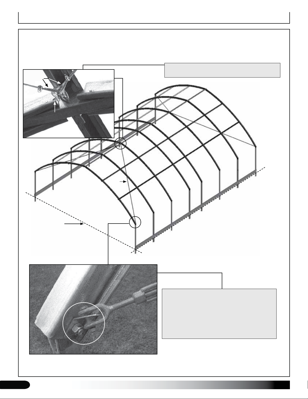
INSTALL AND TIGHTEN ALL CABLES
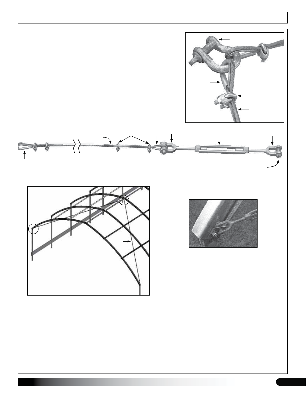
The diagram and inserts below identify the placement and proper way to attach the cable assemblies to the
frame. After attaching all cables to the frame, tighten the turnbuckles. Turnbuckles should be snug and not
overtightened. Shorten cable if you are unable to tighten the turnbuckle to remove cable slack.
Diagram shows the cables attached to the shackle
Thimble
Shackle
and the shackle secured to the eyebolt.
Ground Level
Cable
Frame length and design of your building may
differ from what is shown.
Secure the turnbuckle directly to the cable bracket
attached to each end rafter mounting bolt.
If necessary, use a bar or clamp to slightly bend
the bracket to allow the needed clearance to
install the jaw bolt of the turnbuckle.
20
Actual turnbuckle may differ.
Revision date: 02.10.10

Diagonal Strut Installation
STRUT INSTALLATION
For additional support, attach diagonal struts to the frame between
the end rafter and the first interior rafter at each end. Collect the
needed parts and install the diagonal struts as instructed below.
Required parts and tools:
Frame with 6' rafter spacing use the 105119 (8') strut; frame with •
a 4' rafter spacing use the QH1308 (7') strut.
Secure using FAG340B (5/16" x 3 1/2" bolt), FAME07B flat •
washers, and FALF37B 5/16" locknut
Tape measure, marker, hammer, vise grip, center punch, and drill •
with 3/8" drill bit
Complete these steps:
Using a vise grip (or similar tool) or a vice, bend each flattened 1.
end of the strut as shown in the diagram and photos to the right.
When installed, ends are tight to the frame.
ATTENTION: Verify you have selected the correct strut. Some
frames include struts of different lengths. Consult the diagrams in
the Quick Start section for your building for additional details.
Diagonal Strut
Position strut as shown (lower-right photo) 2. between the end rafter
and first interior rafter. (Adjust position so strut does not interfere
with any other building component.)
Mark the mounting hole locations and drill holes using a 3/8" drill bit.3.
Insert a bolt with washer through the mounting holes and add another washer and locknut.4.
Tighten the nut to secure the strut to the frame.5.
Continue by installing the remaining diagonal struts.6.
A
C
Drill 3/8"
hole.
B
D
Secure with 5/16"
bolt, washers,
and locknut.
Bend strut ends as shown.
Interior
Rafter
A & B
End
Rafter
Diagonal Strut
Diagrams above show how to secure strut to the
assembled frame.
Revision date: 02.10.10
C & D
Diagram above shows strut position as seen
from the inside of the frame.
21
Mounting Foot-to-Rafter Strut Installation
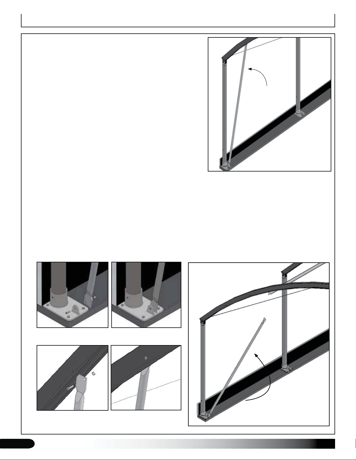
MOUNTING FOOT-TO-RAFTER STRUT INSTALLATION
Frames that include the mounting feet also include an additional
strut running from the foot to the rafter. Complete the steps below
to install the struts.
NOTE: If your building includes ground posts, skip this section and
read ANCHOR THE ASSEMBLED FRAME information on the next
page.
Required parts and tools:
105119 (8') struts•
Secure using FAG330B (5/16" x 1" bolt), FAME07B flat •
washer, and FALF37B 5/16" locknuts
Tape measure, marker, hammer, center punch, and drill with •
3/8" drill bit
Complete these steps:
Take a strut and loosely attach it to the rafter foot using the 5/16" fasteners listed above.1.
Swing the diagonal strut up into position until it reaches the underside of the rafter.2.
Foot-to-Rafter
Strut
Mark the hole location and drill a mounting hole using the 3/8" drill bit.3.
Insert the bolt through the rafter hole and through the mounting hole in the diagonal strut.4.
Add a flat washer and locknut and tighten to secure the strut to the rafter.5.
Return to the lower 5/16" bolt and tighten that locknut.6.
Repeat to attach all remaining struts.7.
STEP 1: Loosely secure strut to foot using 5/16" x 1" bolts,
washers, and locknuts.
STEP 2 & 3: Swing strut up and into
position. Mark the hole location on the
rafter, and drill using a 3/8" drill bit.
STEP 4 & 5: Secure upper end of strut to rafter using the
5/16" x 1" bolt and related washer and nut. Tighten upper and
lower 5/16" nuts.
22
Revision date: 02.10.10
 Loading...