

Page 1

CLEARSPAN™ GREENHOUSES
ClearSpan™
Round Style Clear View Greenhouses
©2011 ClearSpan™
All Rights Reserved. Reproduction
is prohibited without permission.
Revision date: 07.22.11
Photo may show a different but similar model.
STK# DIMENSIONS
106185 20' W x 10' 7" H x 20' L
106186 20' W x 10' 7" H x 24' L
106187 20' W x 10' 7" H x 36' L
106188 20' W x 10' 7" H x 48' L
1
Page 2
CLEARSPAN™ GREENHOUSES
LOCATION
Choosing the proper location is an important step before
you begin to assemble the structure.
The following suggestions and precautions will help you
determine whether your selected location is the best
location.
YOU MUST READ THIS DOCUMENT BEFORE YOU
BEGIN TO ASSEMBLE THE SHELTER.
Thank you for purchasing this ClearSpan™ greenhouse.
When properly assembled and maintained, this product will
provide years of reliable service. These instructions include
helpful hints and important information needed to safely
assemble and properly maintain the greenhouse. Please
read these instructions before you begin.
If you have any questions during the assembly, contact
Customer Service at 1-800-245-9881 for assistance.
SAFETY PRECAUTIONS
Wear eye protection.•
Wear head protection.•
Wear gloves when handling metal tubes.•
Use a portable GFCI (Ground Fault Circuit Interrupter) •
when working with power tools and cords.
Do not climb on the greenhouse or framing during or •
after construction.
Do not occupy the greenhouse during high winds, •
tornadoes, or hurricanes.
Provide adequate ventilation if the structure is •
enclosed.
Do not store hazardous materials in the greenhouse.•
Never erect the structure under power lines.•
Identify whether underground cables and pipes are •
present before preparing the site or anchoring the
structure.
Location should be away from structures that could •
cause snow to drift on or around the building.
Do not position the greenhouse where large loads •
such as snow and ice, large tree branches, or other
overhead obstacles could fall.
Always check local building codes before you begin. •
SITE
After choosing a location, proper preparation of the site is
essential. The following site characteristics will help ensure
the integrity of the structure.
A level site is required• . The site must be level to
properly and safely erect and anchor the structure.
If the site is not level, use footings to provide a secure •
base to assemble the structure. Pre-cast concrete
blocks, pressure-treated wood posts, or poured
footings are all acceptable when properly used. (Some
shelters use ground posts or rafter feet.)
Drainage: Water draining off the structure and from •
areas surrounding the site should drain away from the
site to prevent damage to the site, the structure, and
contents of the structure.
Provide proper ingress and egress to prevent •
entrapment.
ANCHORING INSTRUCTIONS
Prior to assembling this greenhouse, please read the
MUST READ document included with the shipment.
WARNING: The anchor assembly is an integral part
of the greenhouse construction. Improper anchoring
may cause greenhouse instability and failure of the
structure. Failing to anchor the greenhouse properly
will void the manufacturer’s warranty and may cause
serious injury and damage.
2
WARNING: The individuals assembling this structure
are responsible for designing and furnishing all
temporary bracing, shoring and support needed during
the assembly process. For safety reasons, those who
are not familiar with recognized construction methods
and techniques must seek the help of a qualified
contractor.
Revision date: 07.22.11
Page 3

ASSEMBLY PROCEDURE
Following the instructions as presented will help ensure
the proper assembly of your greenhouse. Failing to follow
these steps may result in an improperly assembled and
anchored greenhouse and will void all warranty and
protection the owner is entitled to.
The steps outlining the assembly process are as follows:
Verify that all parts are included in the shipment. Notify 1.
Customer Service for questions or concerns.
Read these instructions, the Must Read document, and 2.
all additional documentation included with the shipment
before you begin assembling the greenhouse.
Gather the tools, bracing, ladders (and lifts), and 3.
assistance needed to assemble the greenhouse.
Check the weather 4. before you install the roof cover
and any panels (if equipped). Do not install covers or
panels on a windy or stormy day.
Re-evaluate the location and site based on the 5.
information and precautions presented in the
documentation included with the shipment.
Prepare the site (if applicable).6.
Assemble the frame components in the order they are 7.
presented in these instructions.
Assemble the frame including the struts (if equipped). 8.
Consult the 9. MUST READ document and properly
anchor the assembled frame.
Install the end wall framing. (End walls are optional 10.
items for some shelter types.)
Install, tighten, and secure the end wall end panels and 11.
doors.
Install, tighten (if applicable), or secure the main cover. 12.
Read the care and maintenance information at the end 13.
of these instructions.
Complete and return all warranty documents as 14.
instructed.
LIST OF WORDS AND PHRASES
CLEARSPAN™ GREENHOUSES
Band Clamp: • Clamp used to connect the end wall
framing to the rafter pipe. In some cases, band
clamps are also used to connect diagonal struts to the
assembled frame.
Clip or Fabric Clip:• A short, half-section piece of
conduit (cut lengthwise) used to secure the end panel
cover to the leg or rafter assembly. The clip or fabric
clip is typically fastened in place using self tapping Tek
screw.
Conduit: • An assembly of pipes used to secure the
main cover and end panels (if equipped). Purlins
and some strut assemblies also consist of connected
pipes to form a conduit. Each pipe joint of a conduit
assembly is secured with a self-tapping Tek screw to
prevent separation. Some conduit assemblies are used
to secure larger end panels and main covers. These
conduits typically consist of sections of PVC tubing
glued at the joints.
Cross Connector: • Any one of the metal brackets
used to "connect" or secure a purlin to a rafter. Crossconnectors are typically pictured on the Pictorial Parts
Guide page or in the Quick Start section (if present).
End Panel: • Fabric or material used to cover the end
wall assemblies. End wall assemblies are optional for
many shelters.
Must Read Document:• This document includes
building and shelter anchoring instructions, steps for
end wall reinforcement, safety precautions, and notices
and warnings. The Must Read document is sent with
all shelters and buildings. If you did not receive a Must
Read document, contact Customer Service to request
one.
On-Center:• Term used to describe a measurement
taken from the vertical center of the rafter or frame
member to the vertical center of another.
Purlin:• The pipe assembly that runs perpendicular to
the rafters or framework that supports the main cover.
Purlins are found on the sides and roof areas of the
assembled frame, are evenly spaced, and typically run
from the front to the back of the shelter.
Plain or Straight Pipe:• A term used to describe a pipe
that has the same diameter or width throughout its
entire length.
Before you begin, it is important to become familiar with the
words and phrases used in this instruction manual.
These words and phrases are common to most
ClearSpan™ shelters and identify the different parts of
the shelter. (Some are used in this document. Others may
not apply to this particular shelter.) These terms describe
the shipped parts and can also be found on the materials
list/spec sheets included with the shipment. To aid in the
assembly, read through the following definitions before you
begin to assemble your shelter.
Revision date: 07.22.11
Strut:• A strut is usually a length of pipe with two
flattened ends and is used for diagonal bracing of the
shelter frame. A strut is typically secured to the frame
work by special brackets and bolts.
Swaged End or Swaged Pipe:• The term “swaged''
refers to the tapered end of the pipe or tube. Swaged
ends of a pipe can be inserted into couplers and the
straight ends of other pipes.
Tek Screw:• A self-tapping fastener used to secure pipe
joints and to fasten brackets to rafters.
3
Page 4

CLEARSPAN™ GREENHOUSES
REQUIRED TOOLS
The following list identifies the main tools needed to
assemble the shelter. Additional tools and supports may be
needed depending on the structure, location, and
application.
SPECIAL NOTE: Baseboards for Frame
These instructions describe installing a baseboard
(recommended) at ground level along each side of the
frame. The baseboard runs from the front to the back of the
frame.
Tape measure or measuring device•
Marker to mark locations on the pipes•
Variable speed drill and impact driver (cordless with •
extra batteries works best)
Metal-cutting saw•
Wrenches and impact socket set, or an adjustable •
wrench
Scissors, utility knife, or tin snips•
Hammers and gloves•
Adjustable pliers and self-locking pliers•
Ladders, work platforms, and other machinery for lifting •
designed to work safely at the height of the building
Rope/cable for temporary rafter bracing during frame •
assembly
UNPACK AND IDENTIFY PARTS
The following steps will ensure that you have all the
necessary parts before you begin to assemble the shelter
frame.
This baseboard is not included with the shipment and must
be supplied by the customer. Treated or recycled plastic
lumber works well for a baseboard.
Use the included 1/4" x 4" (FAH009B) carriage bolts
and the 1/4" zinc nuts (FALB01B) to attach a customersupplied baseboard. Depending on the dimensions of the
baseboard, alternative customer-supplied fasteners may be
needed.
During the installation, align the baseboard with the center
of the end rafter. Do not allow the baseboard to extend
beyond the end rafters at either end of the frame. Doing so
will interfere with the installation of the end wall corrugated
panels.
The baseboard, when installed properly, helps prevent the
ground posts from sinking into the ground when anchored.
Depending on the building, it also provides a surface to
attach struts or other building components.
Consult these instructions or contact Customer Service for
additional information regarding baseboards.
Unpack the contents of the shipment and place where 1.
you can easily inventory the parts. Refer to the Bill of
Materials/Spec Sheets.
Verify that all parts listed on the Bill of Materials/Spec 2.
Sheets are present. If anything is missing or you have
questions, consult the Pictorial Parts Guide and all
diagrams for clarification, or contact Customer Service.
NOTE: At this time, you do not need to open the plastic
bags containing smaller parts such as fasteners or
washers (if equipped).
QUICK START GUIDE
For a quick overview of the building and its components,
consult the information and diagrams in the Quick Start
section near the back of these instructions.
4
Revision date: 07.22.11
Page 5
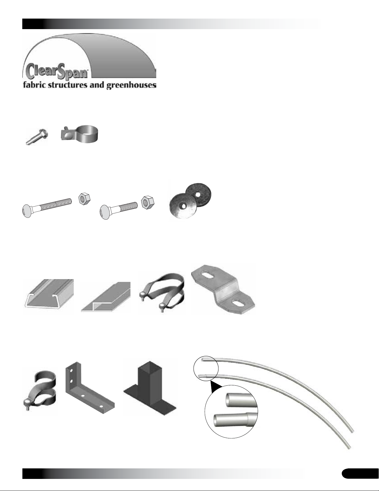
The following graphics and photos will help you identify the
different parts. (Some parts are not shown.)
CLEARSPAN™ GREENHOUSES
FA4482B
Tek Screw
(short)
FAH009B & FALB01B
Carriage Bolt & Hex Nut
102197
Aluminum
U-Channel Profile
QH1402
Band Clamp
104548
End Cap Profile
Doors/Fans/Vents
FAH320B & FALB32B
Carriage Bolt & Hex Nut
102548
Cross Connector
102921
Neo-bonded
Galvanized Washers
104074
Square-to-Round Tube
Connect Bracket
102856
End Clamp
Revision date: 07.22.11
QH1330
Angle Bracket
104624
Square Tube Fitting
Plain
Swaged
Swaged and Plain Rafter Sections
5
Page 6
CLEARSPAN™ GREENHOUSES
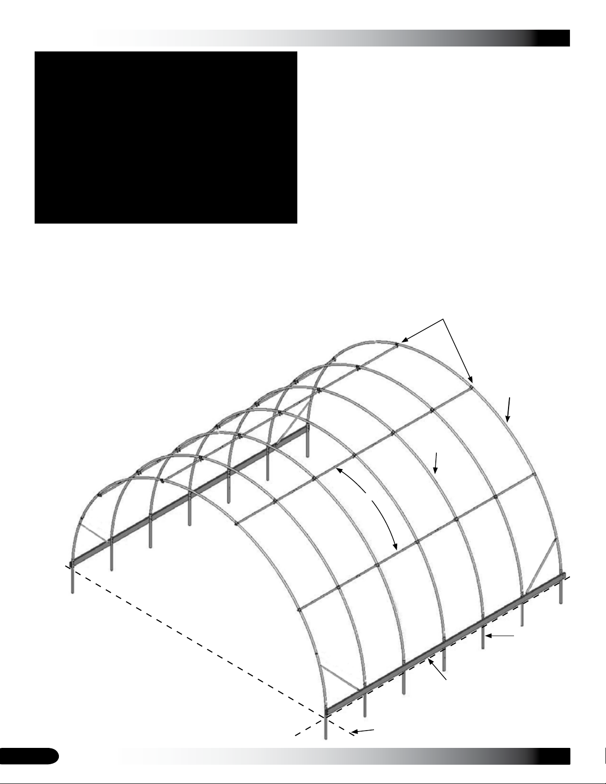
OVERVIEW
This section describes assembling your Round Style
Greenhouse. For details, please see section, Assembling
the Round Style Greenhouse Components. See illustration
below to identify main parts of greenhouse.
Locate the required parts for each assembly procedure.1.
Assemble the rafters and frame.2.
Round Style Clear View
Greenhouse
ATTENTION: Position purlins evenly during the
frame assembly. Use the rafter pipe joints as
guides when installing the end clamps, cross
connectors, and purlins.
Attach customer-supplied baseboards and install struts.3.
Prepare and attach end panels. 4.
Install the polycarbonate roof panels.5.
Assemble and install sliding doors.6.
Interior
Rafter
Purlins
End Rafter
Frame shown may differ slightly from actual frame.
6
Ground
Post
Baseboard is
supplied by
customer.
Ground
Level
Revision date: 07.22.11
Page 7
LAY OUT THE BUILDING SITE
After the site is prepared, lay out the building site.
Taking these steps before assembling the shelter saves
time and ensures that the structure is positioned as
desired.
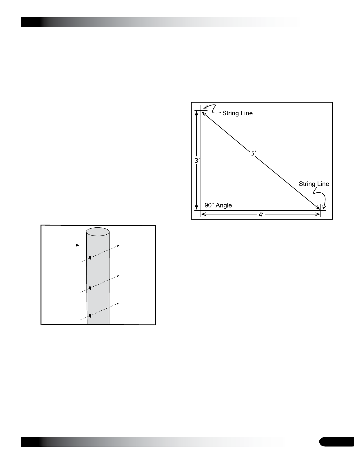
Drive ground posts to the proper depth. Width of the shelter
is measured from the center of one ground post to the
center of the remaining ground post.
SQUARE THE SITE
Gather the parts:
Ground posts•
5/16" x 2-1/2" machine bolts •
5/16" nuts•
Identify a corner where a ground post will be positioned 1.
and drive the first ground post into the ground.
NOTE: Insert the ground post driver into the top of
the ground post to protect the post and drive the post
into the ground. The top of the post will be eleven (11)
inches above the finished grade when properly driven.
Ground
Post
CLEARSPAN™ GREENHOUSES
Use a transit or line level to drive the second corner 3.
post to the same depth as the first ground post.
String a line at least as long as the building from the 4.
first stake at 90°.
NOTE: A transit can be used to ensure an accurate 90°
angle, or the 3-4-5 rule can be used. Refer to diagram.
Using multiples of 3-4-5 such as 6-8-10 or 12-16-20
helps to maintain an accurate 90° angle.
After squaring the position of the building, measure 5.
the length (center-to-center) and drive the next corner
ground post.
Outside of
Shelter
Inside of
Shelter
ATTENTION: Position the pre-drilled holes facing to the
inside/outside of the shelter so they can be aligned with
the bolt holes in the rafter legs.
To align the bolt holes in the ground posts with those
in the rafter after driving the ground posts, insert a
tapered rod or pry bar into a ground post bolt hole and
turn the post using the rod or pry bar.
After the first corner ground post is in place, string a 2.
line the width of the building (center-to-center) and
drive the second ground post into the ground just
enough to hold it in place.
Repeat the same step for the last corner post. 6.
NOTE: The distance measured diagonally between
corner posts must be equal for the building to be
square.
Check all dimensions (and adjust if needed) before 7.
driving the remaining posts to the required height.
After all corner posts are accurately installed, tie a 8.
string line between the tops of the corner ground posts
on the same side of the shelter. The string is used to
identify the tops of all remaining ground posts. The
string must remain tight and level.
Use a tape measure to mark the 48" on-center 9.
locations of the remaining ground posts.
Drive the remaining ground posts into the ground at the 10.
required 48" on-center width and the height identified
by the string.
NOTE: Verify that the holes in the ground posts are in
the proper position and that each post is plumb and
driven to the correct depth. See Step 1 if needed.
Continue with the 11. Rafter Assembly steps that follow.
Revision date: 07.22.11
7
Page 8
CLEARSPAN™ GREENHOUSES
ASSEMBLING THE ROUND STYLE GREENHOUSE
FRAME COMPONENTS
After the site is prepared and an inventory of parts is
complete, continue with the rafter assembly.
NOTE: All rafter assemblies consist of rafter tubes and
purlin clamps. Consult the Front Profile diagram in the
Quick Start section of these instructions before and during
the rafter assembly process.
Assistance is required to assemble the greenhouse frame.
RAFTER ASSEMBLY
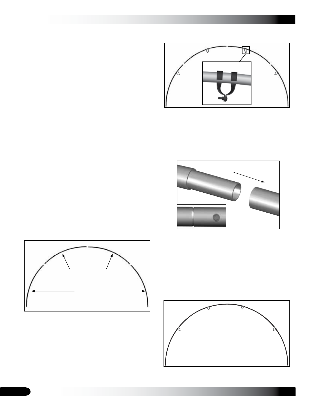
Slide four (4) end purlin clamps (two on each side of 2.
the peak) over the rafter pipes.
Gather the parts:
Rafter pipe (#• 20R1601)
Rafter pipe (#• 20R1602)
Rafter pipe (#• 20R1601D)
End clamps (#• 102856)
Tek screws (#• FA4482B)
Magnetic nut setter 3/8'' x 2-9/16"•
END RAFTER ASSEMBLY
The end rafters include purlin end clamps and band
clamps. Install the purlin end clamps before the different
pipes of the rafters are connected. The band clamps for the
side struts are installed when the two (2) end rafters are set
onto the ground posts.
Select the four (4) pipes needed to assemble the first 1.
end rafter and arrange on a level surface.
(#20R1601)
(#20R1601D)
(#20R1602)
End clamp as seen from outside the assembled rafter.
NOTE: Consult the Front Profile diagram in the Quick
Start section for proper end clamp placement and
position.
After slipping the clamps over the rafter pipes, insert 3.
the swaged end of the rafter pipes into the plain ends
of the pipes to assemble the rafter.
Diagram shows a similar connection.
Once the rafter is assembled, install a Tek screw 4.
through the rafter pipes to secure each joint. See the
diagram above.
IMPORTANT: Verify that you are installing the screw
through the pipe that contains the swaged end of the
adjacent pipe. To prevent damage to the cover and end
panels (if equipped), position the Tek screws so the
heads do not contact the cover when it is installed.
Assembled End Rafter
Repeat steps to assemble the remaining end rafter and 5.
set both end rafters aside.
8
Revision date: 07.22.11
Page 9

RAFTER ASSEMBLY (continued)
INTERIOR RAFTER ASSEMBLY
Complete the following steps for the interior rafters.
CLEARSPAN™ GREENHOUSES
FRAME ASSEMBLY
After all ground posts are driven in place and rafters are
assembled, assemble the frame.
Select the pipes for the first interior rafter assembly and 1.
position these on the ground as shown.
(#20R1601)
(#20R1601D)
(#20R1602)
IMPORTANT: Interior rafters do not use end clamps.
Instead, cross connectors are attached during the
frame assembly.
Insert the swaged ends of the rafter pipes into the plain 2.
ends of the pipes and secure each joint with a Tek
screw.
NOTE: The baseboards (strongly recommended) shown in
the diagrams throughout these instructions are not included
and must be supplied by the customer.
ASSEMBLE AND PRE-MARK THE PURLINS
The following steps describe one way to speed the
assembly process. Pre-marking the purlins ensures that an
accurate spacing of the rafter assemblies is achieved and
maintained during assembly.
Those familiar with the assembly of similar structures
may elect to skip this procedure and continue with the
ASSEMBLE THE FRAME procedure on the next page.
Gather the parts:
Pipe 1.315'' x 75'' swaged (#131S075)•
Pipe 1.315'' x XX'' plain (#131P0XX)•
Marker and tape measure•
NOTE: The purlins are part of the assembled frame and
run perpendicular to the rafter assemblies. Each purlin
consists of 1.315" x 75" (#131S075) swaged pipes (number
is determined by shelter length) and one (1) 1.315" x XX"
(#131P0XX) plain pipe.
The XX" represents the remaining length required to reach
the end of the shelter. Consult the Spec Sheet for part
identification.
NOTE: For longer frames, it may be easier to assemble
a few rafters at a time and then begin to assemble the
frame.
Once rafters are assembled, assemble the frame.3.
Revision date: 07.22.11
Select the required pipe sections for one purlin and 1.
connect these by inserting the swaged ends of the
pipes into the plain ends until the entire purlin is
assembled.
NOTE: Assemble the purlins in a location that is
accessible during the assembly of the frame, but will
not interfere with the process of lifting and setting the
rafters.
Verify that each pipe joint is properly seated. 2.
NOTE: These pipes are separated during the assembly
procedure. Do not fasten them together at this time.
For the 48" rafter spacing, measure forty-eight and 3.
three-quarters inches (48-3/4") from one end of the
assembled purlin and mark the distance on the pipe.
NOTE: This first measurement is three-quarters (3/4)
of an inch longer than the on-center rafter spacing
to account for the length of purlin pipe that extends
through the end purlin clamp of the first end rafter.
9
Page 10
CLEARSPAN™ GREENHOUSES
FRAME ASSEMBLY (continued)
From the location marked in the previous step, 4.
measure forty-eight inches (48") and make another
mark on the assembled purlin.
Secure the leg pipes to the ground posts using the 2.
5/16" x 2 1/2" machine bolts and nuts.
Rafter
Continue to mark the purlin in 48" intervals until all 5.
locations are marked. These marks help to maintain
the 48" on-center rafter spacing of the shelter during
assembly.
Repeat this procedure until all assembled purlins are 6.
marked.
After assembling all rafters and pre-marking the purlins, 7.
assemble the frame.
ASSEMBLE THE FRAME
After all ground posts are driven in place, rafters are
assembled and purlins pre-marked, assemble the frame.
Gather the Parts:
All rafter assemblies and pre-marked purlins•
Band clamps (#• QH1402)
Cross connector (#102548)•
5/16" x 2-1/2" machine bolts and 5/16" nuts •
Lifts, ladders, and assistants•
Band
Clamp
Outside of
Shelter
Inside of
Shelter
Ground
Post
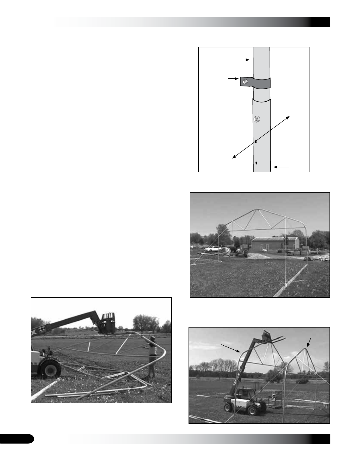
Use rope or cable to brace the rafter in position. 3.
Rope or cable to temporarily brace rafters•
Carefully stand the 1. first end rafter, slide a band clamp
onto each rafter leg, and place the leg pipes in the first
set of ground posts.
Brace the rafter in place to keep it straight. Depending
on the frame size, a lift and additional assistants may
be needed. Consult Quick Start section for details.
Rafter shown differs in design.
Carefully position the first interior rafter in place and 4.
secure the leg pipes to the ground posts.
End Rafter
1st Interior Rafter
Rafter shown differs in design.
ATTENTION: Stand the rafter so the nuts and bolts of
the end clamps are to the inside of the frame.
10
Rafter shown differs in design.
Revision date: 07.22.11
Page 11
FRAME ASSEMBLY (continued)
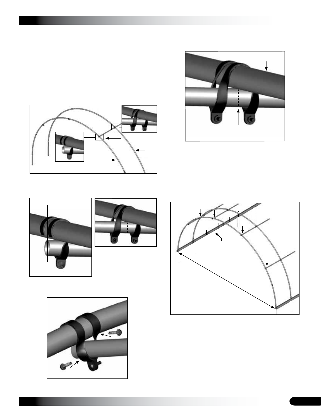
As the second rafter is steadied, remove one section of 5.
pipe from one assembled purlin.
NOTE: Work from the end of the purlin where the
first measurement was taken during the pre-marking
procedure if that procedure was used.
Insert the purlin pipe through an upper end clamp of 6.
the end rafter and through a cross connector placed in
the same position on the interior rafter. Consult Quick
Start section for purlin location per frame.
End Rafter
Align the plain end of the purlin with the center of the 7.
end rafter and rotate the purlin pipe so that the first
mark is visible (near the clamp of the interior rafter).
Do not allow the
purlin to extend
beyond the end
rafter.
Interior
Rafter
CLEARSPAN™ GREENHOUSES
Move to the interior rafter and align the mark on the 10.
purlin with the center of the rafter to maintain the proper
rafter spacing.
Interior Rafter
Purlin
Align mark with
center of rafter.
Verify that the rafter spacing is forty-eight inches (48") 11.
on-center (adjust as needed) and tighten the cross
connector.
Secure the cross connector to the rafter using a Tek 12.
screw. See Quick Start section if needed.
Repeat Steps 6-12 to install the first section of each 13.
purlin assembly for the first two rafters.
End rafter view
Tighten the end clamp and secure it to the rafter with a 8.
Tek screw.
End Rafter
Step 9
Install Tek screw through end clamp and into the purlin 9.
pipe.
Purlin
Interior rafter
Customer-supplied
baseboards: See next
section for installation tips.
20' wide
center-to-center
Choose another interior rafter assembly and set it 14.
in position. DO NOT USE THE REMAINING END
RAFTER.
Secure the rafter legs to the ground posts as previously 15.
described and steady the rafter.
Remove another section of purlin pipe from each pre-16.
marked purlin assembly and attach these to the rafter.
Verify that the distance between the rafters is 48" 17.
center-to-center. Adjust the rafter forward or backward
as needed to maintain this dimension.
Revision date: 07.22.11
11
Page 12
CLEARSPAN™ GREENHOUSES
FRAME ASSEMBLY (continued)
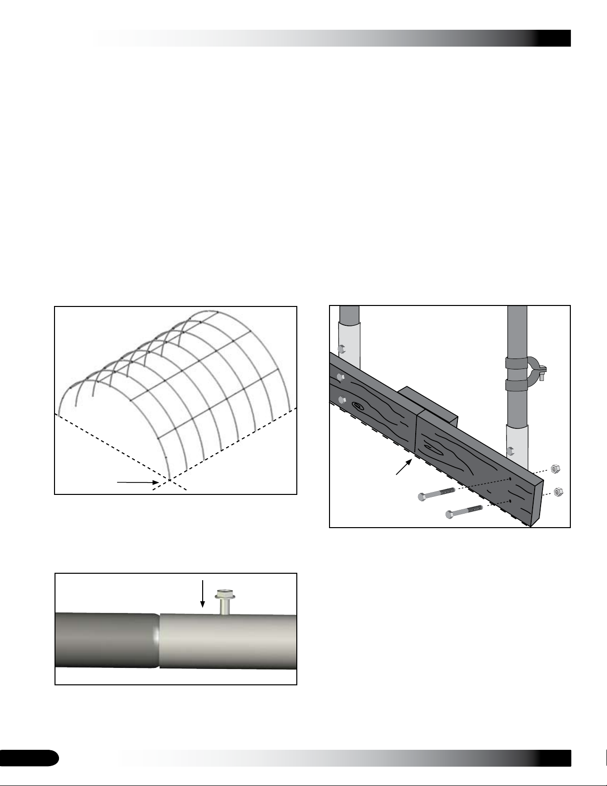
BASEBOARD INSTALLATION (RECOMMENDED)
Secure each purlin pipe joint with a Tek screw. 18.
Repeat the above steps as needed to stand and secure 19.
the remaining interior rafters and purlins to complete
the frame assembly.
Slide a band clamp onto each leg of the remaining 20.
end rafter, secure the rafter to the ground posts, and
attach the purlins to it. Verify that the end clamps are
positioned with the nut and bolt to the inside of the
assembled frame. Refer to the Quick Start section and
previous diagrams if needed.
NOTE: If the last end rafter is plumb and the purlin
extends beyond the end of the rafter, cut the last
section of purlin pipe to the required length.
Typically purlins do not require cutting. Verify that you
have correctly assembled the purlin using the correct
pipes before cutting any pipe to length.
Gather the parts:
Treated or recycled plastic lumber• (supplied by
customer).
1/4" x 4" carriage bolts and nuts (may not work for •
baseboards with a thickness greater than 1-1/2")
NOTE: The following procedure describes one way
to install the recommended baseboards. The size
and type of the baseboard you choose may require
the use of alternative steps. When properly installed,
baseboards run the length of the frame.
On the outside of the frame, attach the first baseboard
to the ground posts using the 1/4" x 4" carriage bolts
and nuts. Continue adding baseboards to complete
the first run. Splices are made between posts as
shown below in the illustration. Use a short section of
baseboard to secure separate baseboards at a splice.
Dashed line shows
ground level.
Frame length may differ from actual frame.
Once all rafters are set and all purlins are in place and 21.
secure, return to each pipe splice of each purlin and
rafter and verify that a Tek screw is installed to secure
the joint. Install a Tek screw if needed.
Inside of
Shelter
Outside of
Shelter
Ground
Level
NOTE: The boards should be at ground level or slightly
into grade to prevent the shelter from sinking and to
create a seal along the bottom. After installing the
baseboards, continue with these instructions.
This baseboard is not included with the shipment and must
be supplied by the customer. Treated or recycled plastic
lumber works well for a baseboard.
The baseboard, when installed properly, helps prevent the
ground posts from sinking into the ground when anchored.
Depending on the building, it also provides a surface to
attach struts or other building components.
Remove any temporary bracing (if needed) and install 22.
the baseboards and side struts.
12
ATTENTION: To prevent interfering with the installation of
the end wall panels, do not allow the end of the baseboard
to extend beyond the end of the end rafter.
Revision date: 07.22.11
Page 13
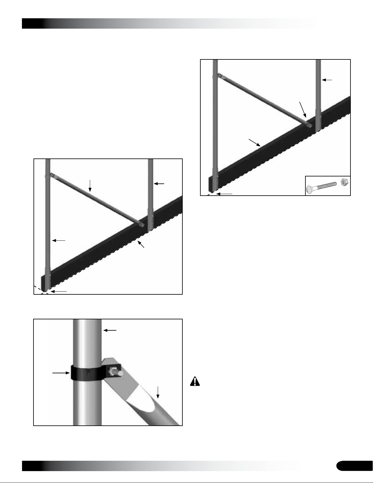
SIDE STRUT INSTALLATION
There are four (4) side struts for the shelter. These struts
are positioned between the end rafters and the first interior
rafter on each side of the shelter.
Complete these steps to install the four (4) side struts:
CLEARSPAN™ GREENHOUSES
Attach the remaining end of the strut to the baseboard 3.
using a lag screw or nut and bolt (not included). See
the diagram that follows for location.
Photo shows the strut attached
to the inside of the customersupplied baseboard.
End
Rafter
Gather the parts:
Struts•
Band clamps (#• QH1402)
Lag screw or nut and bolt (supplied by customer)•
Locate one strut and position it between one end rafter 1.
leg and the leg of the first interior rafter as shown
below.
Strut
End Rafter
Baseboard is required to
secure strut as shown.
Customer supplies the
baseboard.
Ground Level
Attach one end of the strut to the band clamp as shown 2.
in the diagram below.
Attach strut
as shown.
Baseboard
Interior
Rafter
Ground Level
NOTE: A baseboard provides a place to attach each
strut and helps keep the ground posts at the required
depth. The customer is responsible for providing a
baseboard for this frame.
If no baseboard is used, place a band clamp around
the rafter just above the ground post and secure the
lower end of the strut to the band clamp (not shown).
Repeat the above steps to attach the remaining side 4.
struts to the shelter.
After securing the struts, verify that all clamps are 5.
secured with a Tek screw to the rafters.
Continue the next procedure to anchor the assembled 6.
frame.
End Rafter
Band Clamp
Strut
NOTE: Head of bolt on the band clamp must face the
polycarbonate panels.
Revision date: 07.22.11
ANCHOR THE ASSEMBLED FRAME
At this point, anchor the greenhouse frame. Consult the
MUST READ document for anchoring information and
suggestions. Please call customer service at 1-800-2459881 for additional anchoring information.
CAUTION: The anchor assembly is an integral part of
the greenhouse construction. Improper anchoring may
cause instability and failure of the structure to perform
as designed. Failing to anchor the shelter properly
will void the manufacturer’s warranty and may cause
serious injury and damage.
13
Page 14
CLEARSPAN™ GREENHOUSES
END WALL INSTALLATION
The steps to install the end walls for the greenhouse
include the following:
Install end wall framing. (See the diagrams in the Quick 1.
Start section at the back of these instructions. Read the
installing accessories note below.)
Prepare polycarbonate end panels and attach.2.
Assemble doors and attach. 3.
INSTALL END WALL FRAMING (Front and Back)
DO NOT REPOSITION THE END WALL VERTICALS •
USED AT THE SEAM OF TWO (2) POLYCARBONATE
PANELS.
Always consult the installation guides that shipped •
with the accessory for additional precautions,
recommendations, and safety requirements.
Before installing any electrical accessory, consult a •
professional electrician for precautions and additional
assistance.
For gas heaters, a professional, qualified service •
technician must install the unit.
Site variations and different methods for anchoring the
greenhouse may require slight changes to be made to
these instructions. It is the responsibility of the owner/
builder to adapt these instructions as needed to adjust for
these and other differences.
A NOTE ABOUT INSTALLING THE END WALL
FRAMING FOR OPTIONAL HEATERS, VENT FANS, AND
MOTORIZED SHUTTERS (if equipped):
Optional accessories such as heaters, vent fans and
motorized shutter units are typically installed or attached
to the end walls of this greenhouse. Additional horizontal
framing (included) is installed between the vertical end
wall frame tubes to mount these accessories. The spacing
shown for the end wall supports on the end frame diagrams
may be too narrow for the installation of some larger
accessories.
Diagrams do not show framing for the accessories.
When framing the end wall, consult the installation
instructions for the accessories (if equipped), or measure
the width of the accessory to accurately space and position
the end frame tubes.
Consult the panel installation diagrams in the Quick Start
section to identify the verticals that can be moved.
MOVE ONLY THE VERTICAL SUPPORTS LABELED
AS NC (NON-CRITICAL). See Quick Start diagrams.
Before installing any greenhouse accessory, adhere to the
following:
Complete these steps to install the accessory framing:
Based on the installation requirements and precautions 1.
of the accessory, choose a location in the end wall to
mount the accessory, and cut a 1.5" x 1.5" frame tube
to the required length for framing.
Attach these horizontal frame tubes between the 2.
vertical frame tubes of the end wall (at the required
height determined by the installation instructions
included with that accessory) using QH1330 brackets.
INSTALL THE FRONT END WALL FRAME
Refer to the end frame diagrams (Quick Start section).
The materials and parts needed to assemble the end wall
frame include:
Square tube (#102897) & roller assembly (#100356)•
Angle brackets (#QH1330) & band clamp (#QH1402)•
Square tube fitting (#104624)•
Square-to-round tube connect bracket (#104074)•
Carriage bolt (#FAH320) and nut (#FALB32B)•
Tek screws (#• FA4482B)
Locate the square metal tubing for the base tube of the 1.
end wall. The base tube consists of 99" swaged tubes
and one (1) short section cut from a length of square
pipe. See Quick Start section for clarification.
Insert the swaged ends of the tubing into the plain ends 2.
to connect the pieces, measure, and cut to length.
Consult the end frame diagrams before installing the •
accessory horizontal framing.
Move only those verticals labeled as "NC" on the end •
frame diagrams when deciding where to install the
additional horizontal framing for accessories.
Consult the diagrams in the Quick Start section •
showing the polycarbonate panel locations and the
locations of the aluminum trim and profile before
repositioning any end wall vertical.
14
Position this assembled base tube on the ground 3.
between the legs of the end rafter at the front of the
greenhouse and anchor it in place. This base tube will
be directly below and in line with the end rafter.
Revision date: 07.22.11
Page 15
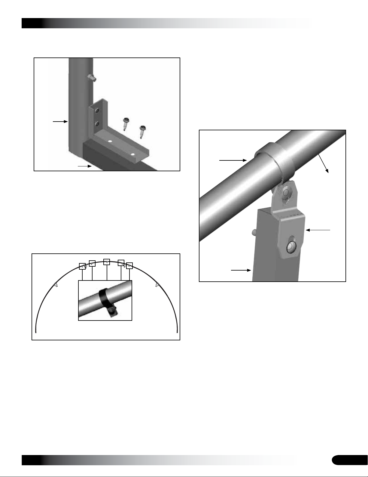
END WALL INSTALLATION (continued)
Secure the base tube between the legs of the end 4.
rafter using an angle bracket and Tek screws.
The bracket shown in this
diagram can be installed with
either its short section (as
shown) or the long section
attached to the ground post.
Ground
Post
Base Tube
CLEARSPAN™ GREENHOUSES
Measure the distance 9. between the top of the base tube
and band clamp (Step 7) to determine the length of the
first vertical section of the door frame tube.
Choose one square tube (#102897), insert the swaged 10.
end of the long tube into the plain end of another tube
and tap with a hammer to properly seat the tubes at the
joint.
On this assembled frame member, mark the length 11.
determined in Step 9 (above) and subtract the amount
needed to account for the square-to-round tube
connect bracket, which is attached to the top of the
frame tube. See the diagram that follows.
End Rafter
On the base tube surface facing the inside of the 5.
greenhouse, install a short Tek screw at each joint and
then locate and mark the center of the base tube.
Consult the End frame diagram (Quick Start section) 6.
and mark the rough opening for the width of the double
door assembly.
Place the band clamps on the end rafter above the 7.
door as shown below. DO NOT TIGHTEN THE BOLTS
AT THIS TIME.
Select the tubing for the two vertical frame supports for 8.
the sides of the double door. Each support includes:
Square tubing (#102897 swaged end): For the •
longer vertical frame members, shorter sections of
tube may need to be cut and added.
One (1) square-to-round tube bracket (#104074)•
Front (or outside)
of the greenhouse
Square-toRound Tube
Connect
Bracket
Vertical Door
Frame Tube
Select a square-to-round tube connect bracket and 12.
attach the bracket to one end of the vertical frame
member. Use a 5/16" drill bit to drill a hole through the
tube and attach the bracket to the tube using a nut and
carriage bolt.
Repeat Steps 9-12 for the remaining vertical frame 13.
member for the door.
With the square-to-round tube connect bracket 14.
attached to the top of each vertical door frame tube,
use the bolt in the band clamp to attach the bracket to
the band clamp. DO NOT TIGHTEN AT THIS TIME.
NOTE: The heads of the bolts for each clamp are to the
outside (or front/back) of the greenhouse. At this point,
the two vertical door frame members should be loosely
attached to the end rafter assembly.
Revision date: 07.22.11
15
Page 16
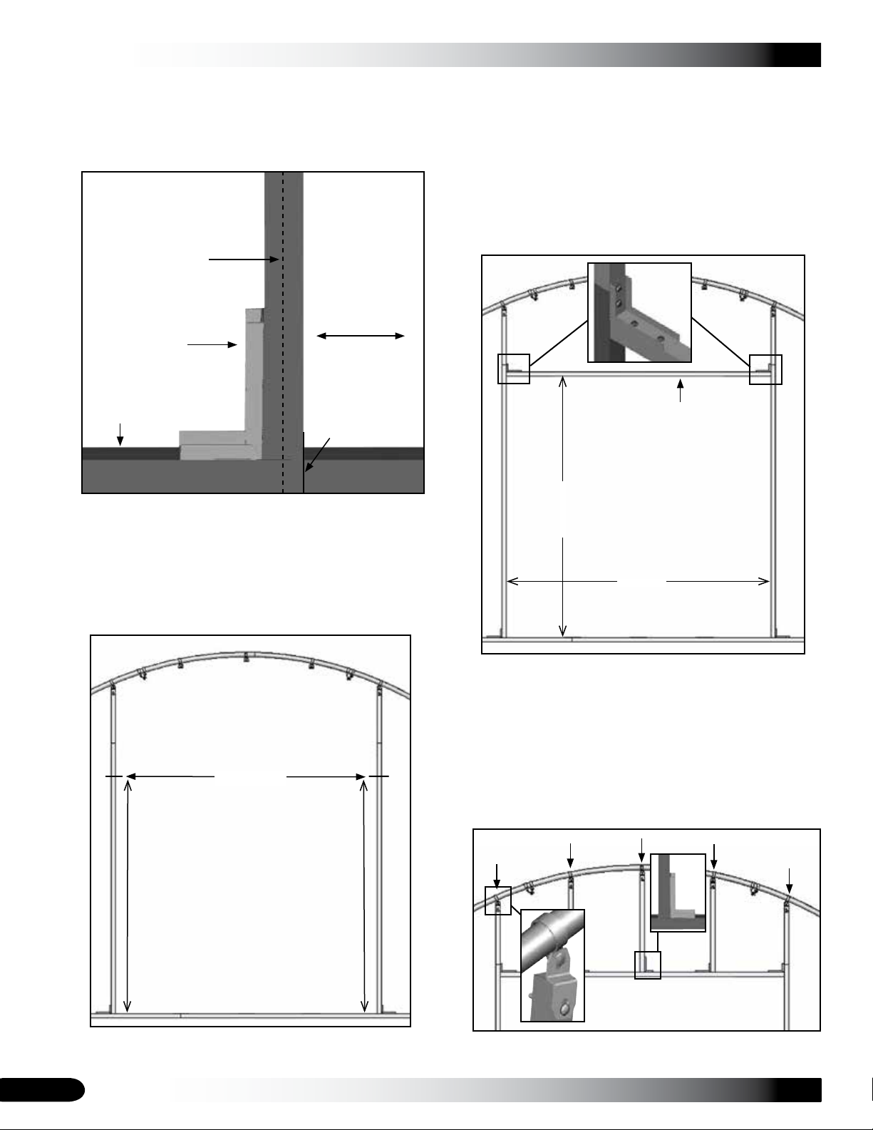
CLEARSPAN™ GREENHOUSES
INSTALL THE END WALL FRAME (continued)
Using the marks on the base tube for the rough 15.
opening for the door, attach the bottom of each vertical
frame member to the base tube using an angle bracket.
Consult the end frame diagram.
Center of Door
Frame Tube
Door Opening
Angle Bracket
Using a level (or other means), verify that one vertical 17.
door frame tube is plumb and tighten the band clamp
bolt to lock the first door frame member in place.
Choose the square tube for the door frame header and 18.
cut the swaged end to the proper length for the width of
the rough door opening.
Using two angle brackets, attach the header tube to 19.
the end wall assembly between the vertical door frame
tubes as shown.
Base Tube
Mark
With the vertical door frame tubes attached at the 16.
bottom and loose at the top, measure each frame
member to locate the height of the rough door opening
and mark the location on the inside of the door frame.
Consult the End Frame diagrams in the Quick Start
section located at the back of these instructions.
Mark Here
Header
89"
Height of rough
door opening
93"
Width
Inside dimensions are shown. Diagrams may show a
different frame used for illustration purposes only.
Verify that both door frame verticals are plumb and 20.
recheck the width of the rough door opening at the top
and bottom. Adjust if needed.
Cut the metal tube for the short, end wall supports 21.
(positioned between the header and the end rafter) and
attach as shown in the following diagram.
89"
Height of rough
door opening
Frame shown may differ from actual frame.
16
89"
Revision date: 07.22.11
Page 17
INSTALL THE END WALL FRAME (continued)
Use the end frame diagram to determine the number of 22.
remaining vertical end frame supports and place one
band clamp on the end rafter for each of the remaining
vertical supports. Use the diagram for the location of
these clamps.
Using the end frame diagrams (Quick Start section), 23.
measure and mark (on the base tube) the locations of
the remaining vertical end wall supports.
Choose the parts for each remaining vertical support 24.
for the end wall framing. Each vertical support consists
of the following parts:
Square tube: Longer verticals may require an •
additional shorter length cut from a longer tube.
One (1) square tube fitting (#104624) to attach the •
support to the base tube of the end wall assembly.
One (1) square-to-round tube connect bracket •
(#104074) to attach the tubing to the band clamp
on the end rafter.
Use the steps presented earlier in these instructions 25.
and the end frame diagrams to measure and cut each
section of square tubing for the remaining vertical
frame members.
ATTENTION: Remember to subtract the amount
needed to account for the square-to-round tube
connect bracket that will be attached to the top of each
remaining frame member.
CLEARSPAN™ GREENHOUSES
With the square-to-round tube connect bracket 27.
attached to the top of the frame member, place a
square tube fitting on the bottom of the frame member.
Align the center of the assembled frame member with 28.
the center mark on the base tube and attach the top of
the frame member to the band clamp on the rafter. Do
not tighten.
Verify that the vertical end wall frame member is plumb 29.
and use the short Tek screws to secure the square tube
fitting to the base tube.
Center Mark
Tighten the top band clamp and30. install a short Tek
screw through the clamp and into the rafter.
Choose a square-to-round tube connect bracket and 26.
attach the bracket to one end of the vertical frame
member. Use a 5/16" drill bit to drill a hole through the
tube and attach the bracket to the tube using a nut and
carriage bolt.
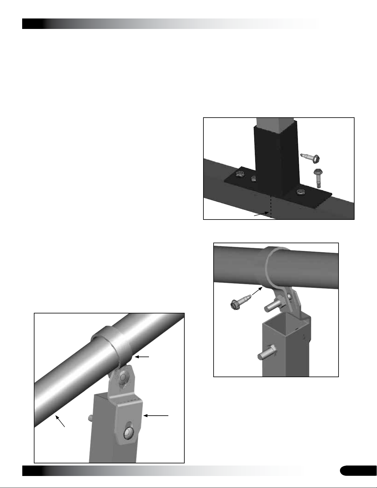
Position all screws, bolts
and clamps so they will
not damage the end wall
panels when panels
are attached to the
end wall frame.
Band Clamp
Square-toRound Tube
Connect
Bracket
End Rafter
Front (or outside)
of the greenhouse
Inside view
of end rafter
Repeat the procedure as needed to assemble and 31.
install the remaining vertical end wall supports.
Return to the bottom of each frame member and install 32.
a short Tek screw through the backside of each tube
fitting to secure the end frame support to the tube
fitting.
Once each end wall is assembled, return to each band 33.
clamp and pipe splice of each base tube and verify that
a Tek screw is installed. Install a Tek screw if needed.
Revision date: 07.22.11
17
Page 18
CLEARSPAN™ GREENHOUSES
INSTALL THE END WALL FRAME (continued)
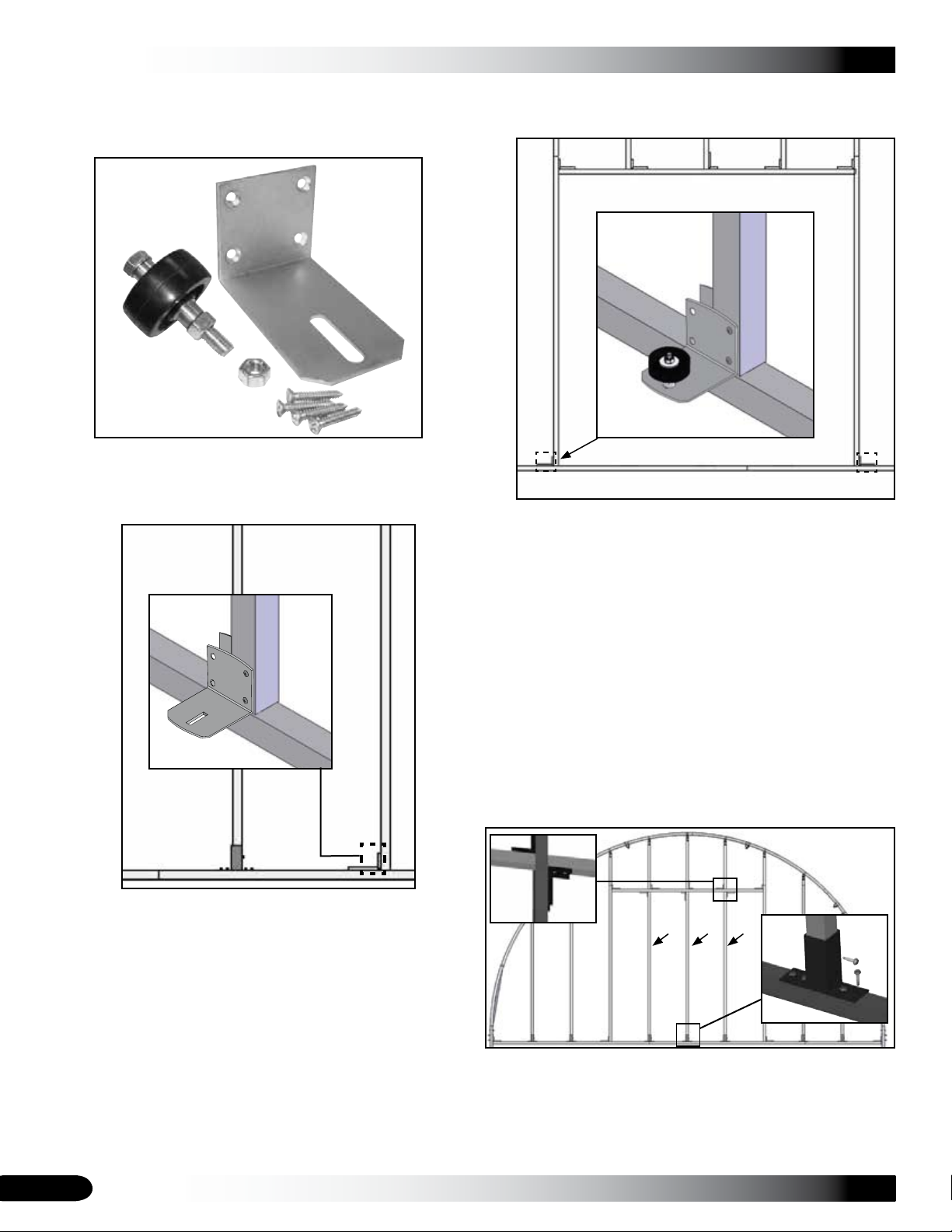
Locate the 100356 lower roller assembly and remove 34.
the roller, bushings, screws, bolt and nuts.
Looking at the rough door opening of the assembled 35.
end wall, secure the angle bracket in the lower-left
corner of the opening as shown below.
Repeat the steps to attach the remaining roller 37.
assembly to the lower-right corner of the rough door
opening. View as seen from outside the frame.
Continue with installing the framing for the back end 38.
wall.
INSTALL THE BACK END WALL FRAME
X
X
NOTE: Use FA4482 Tek screws. Do not use the holes
marked with an X in the photo above.
If using the screws supplied with the roller assembly,
drill two (2) pilot holes into the frame and attach roller
assembly using two (2) screws.
Reattach the roller and related parts to the angled 36.
bracket attached to the end wall frame.
NOTE: Do not tighten the roller assembly at this time. It
is adjusted and tightened when the door is installed.
The end wall framing for the back of the greenhouse is
assembled in the same way as the front end wall.
If the back wall includes the optional double door kit, repeat
the End Wall Installation procedure and install the framing
for the remaining end wall.
CONSULT THE QUICK START SECTION FOR
ADDITIONAL FRAMING INFORMATION.
If the back end wall does not include an optional double
door kit, install vertical frame members in the framed
opening. See the diagram below.
Join and cut the tubes to the required length and attach 1.
to the end wall framing.
Attach the frame support at the top and bottom as 2.
previously described.
18
Continue with installing the end panels.3.
Revision date: 07.22.11
Page 19
END PANEL INSTALLATION
After the end wall framing is attached, the end wall panels
are installed.
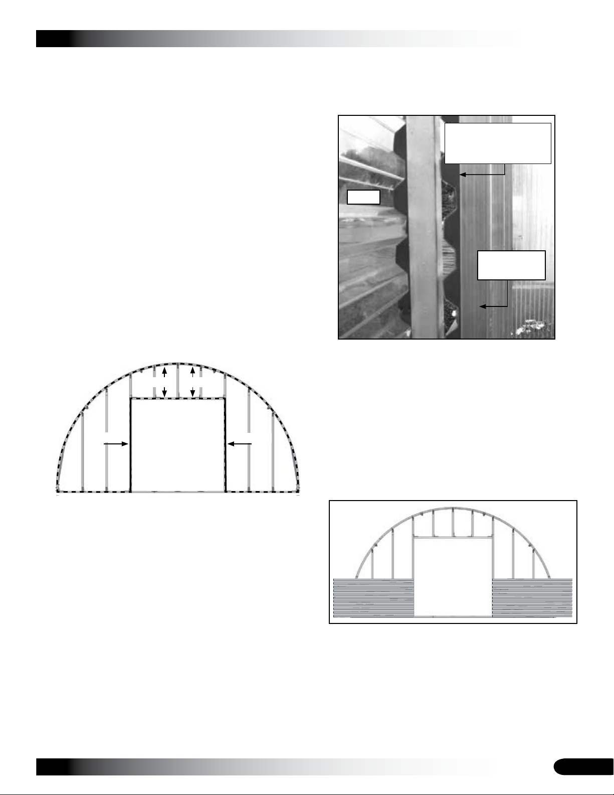
The following procedure describes one way to install the
end panels. This procedure installs the panels so the
corrugated ribs run horizontally.
Complete these steps to install the end panels.
NOTE: End panels overlap each other and are attached to
each frame member of the end wall and to the rafter.
Use Tek screws (#FA4482) and washers (#102921) to
secure all polycarbonate panels to the framing.
ATTENTION: Both end walls are covered using 4' x 8'
panels. Consult the Front and Back End Panel Details
diagrams in the Quick Start section of this document.
Locate the vertical closure foam strips (104710), 1.
remove the plastic film to expose the adhesive, and
attach the strips to the bottom frame member of the
end wall and to the outside edge of the end rafter.
104710104710
CLEARSPAN™ GREENHOUSES
Install a Tek screw and washer to hold the panel and 4.
foam seal in place.
ATTENTION: DO NOT install the screw near the top of
the end panel where the next panel will overlap.
Install foam strip
(104709) under the
corrugated panel.
Door
End Wall
Vertical Tube
Photo shows the foam strip (104709) under the panel
along the edge of the door frame as seen from inside
the greenhouse.
Install the next bottom end panel and foam strip to the 5.
end wall frame on the other side of the door.
104709
Dashed lines show where to attach the vertical foam
closure strips (#104710). The solid lines show where to
install the horizontal closure strips (#104709).
NOTE: The foam stripping regarding the arch of the
rafter is installed on the end wall face of the rafter. It is
used to seal the edges of the end panels.
Choose one 8' corrugated panel, set it in place to one 2.
side of the rough door opening, and secure it to the end
wall frame tube in a few places.
DO NOT attach it along the edges at this time.
ATTENTION: All screws that hold the panels to the
frame are spaced at approximately 24" apart.
Take a section of the horizontal foam stripping (104709) 3.
and install it under the edge of the end panel to seal
the edge along the door frame.
104709
After installing all bottom end panels on each side of 6.
the door, secure the outside end panels to the rafter
using Tek screws and washers.
NOTE: Do not completely secure the panels in place
until the next panel (moving up) is installed.
Panels are not to scale.
CONSULT THE DIAGRAMS IN THE QUICK START
SECTION FOR DETAILED INFORMATION.
Revision date: 07.22.11
19
Page 20
CLEARSPAN™ GREENHOUSES
END PANEL INSTALLATION (continued)
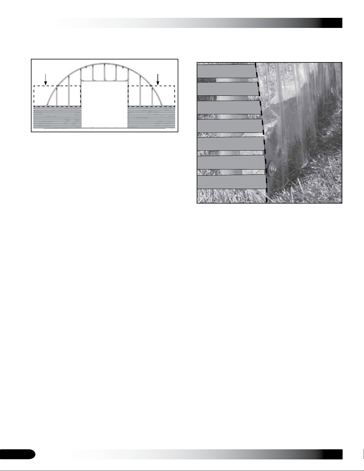
Choose the next 8' panel and overlap the top edge of 7.
the bottom panel with the bottom edge of the top panel.
8' Panel 8' Panel
NOTE: The top panel will overlap the bottom panel by
one rib. (Panels are not to scale.)
Install the horizontal foam strip (104709) to the door 8.
edge of the panel as previously described.
Secure the top panel to the end wall framing as 9.
previously described.
Once the top panel is secured, finish securing the 10.
bottom panels to the end wall framing (as needed) and
add the next top panel.
Repeat the process for the top panel regarding the 11.
other side of the door.
Continue to install the remaining panels until the end 12.
wall is covered.
Once the door end of the greenhouse is covered with 13.
end panels, cut all panels to the width of the end wall
using the rafter as a guide.
ATTENTION: The roof panels can be installed on the
outside of a baseboard as shown in the next photo, or
flush with the top edge of the baseboard (not shown).
If you want to attach the roof panels to the outside of a
baseboard, use the installed baseboard as the outside
edge of the end wall at the bottom when cutting the
lower end wall panels to width. See the photo in the
next column for details. Use the rafter as the outer
edge of the end wall if you install the roof panels flush
to the top of the baseboard.
The gray bars in the photo below represent the
horizontal ribs of the corrugated panels. The dashed
line represents the edge of the roof panel that is
installed in the next procedure.
The roof panels are attached to the outside of the
installed baseboard as shown above. When cutting
the corrugated end panels to the proper width, cut the
panel so that it extends beyond the end rafter to cover
the small area above the installed baseboard.
ATTENTION: Allow the roof panels to extend beyond
the end of the rafters an inch or so to create a drip
edge.
Panels can be installed to the top of the baseboard.
Move to the remaining end wall and repeat the steps to 14.
install the end panels for that wall.
NOTE: The width of the end wall determines how
the end panels are installed. When setting the end
panels in place, the excess end panel material can be
removed, or the next panel can overlap it, depending
on how much panel remains.
End panels are attached to each frame member of the
end wall and to the rafter. Panels must overlap each
other.
CONSULT THE BACK END PANEL DETAILS PAGE IN
THE QUICK START SECTION FOR DETAILS.
20
Revision date: 07.22.11
Page 21
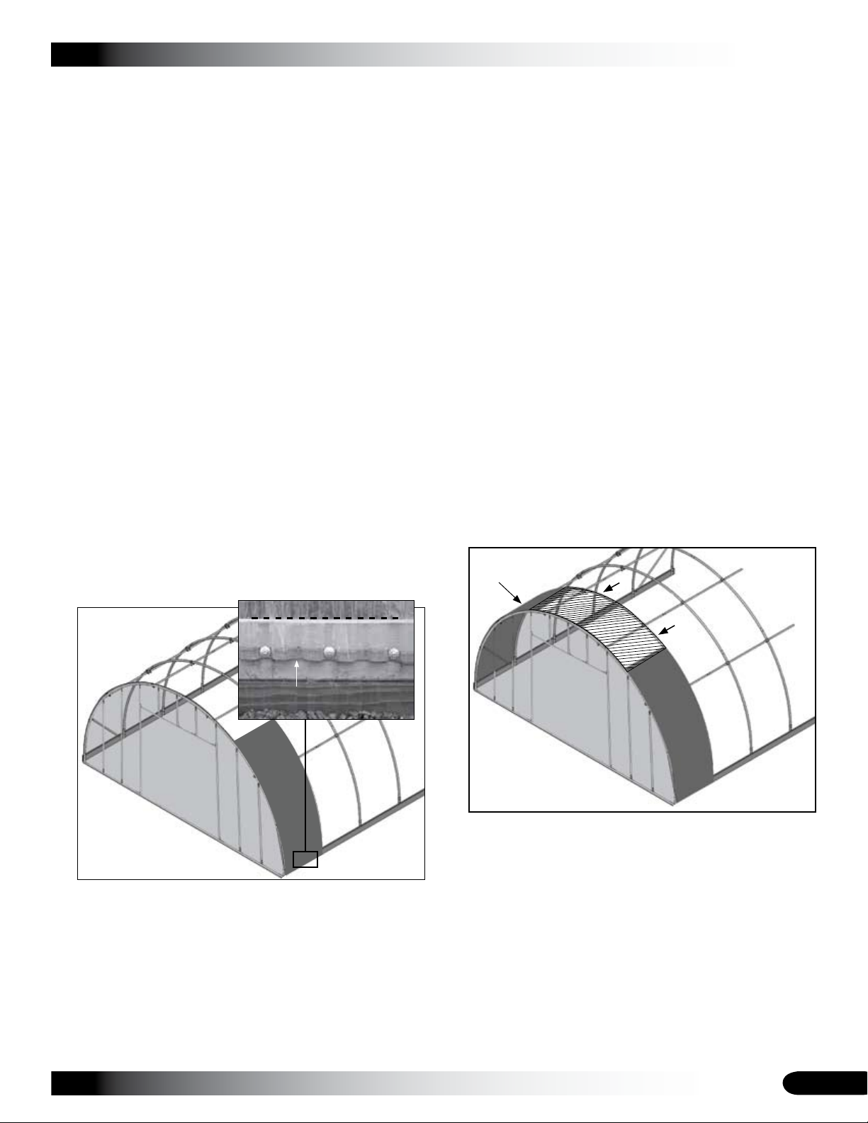
INSTALL THE CORRUGATED ROOF PANELS
The corrugated roof panels are attached to the tops of each
rafter using Tek screws and washers. These panels are
designed to span the 48" on-center rafter spacing, which
allows each panel to overlap the previous panel.
CONSULT THE MAIN COVER DETAILS DIAGRAM IN
THE QUICK START SECTION OF THIS DOCUMENT
FOR ROOF PANEL INSTALLATION DETAILS.
Panels are installed beginning at one end of the
greenhouse and working toward the other end. All panels
are installed between two rafters and over the greenhouse.
The overlap seams are secured before moving to the next
rafter.
REQUIRED PANELS: Use three 4' x 12' panels to cover
the area between same two rafters.
Complete the steps that follow to install the roof panels.
ATTENTION: Tek screws (#FA4482) and washers
(#102921) are used to secure all polycarbonate panels to
the framing.
Choose one 12' corrugated polycarbonate panel and 1.
position it between the end rafter and the first interior
rafter. Start the panel an inch above the lower edge of
the baseboard as shown below.
CLEARSPAN™ GREENHOUSES
Place the panel at the desired height above the ground 2.
and on top of the end rafter. Align panel with the center
of the rafter pipe and attach the panel to the top of the
end rafter and to the baseboard.
ATTENTION: Install Tek screws and washers at 16"
intervals along the panel edges for all roof panels. The
lower and upper ends where different panels overlap
are secured every 12". Be sure to position the panel so
that it reaches the second rafter.
DO NOT attach the first panel to the second rafter at
this time. Attach it to the end rafter only. The next panel
will overlap the previous panel, which is the repeated
pattern for the length of the greenhouse.
DO NOT secure the upper end of the first panel to the
top of the end rafter until the top panel is in position.
Choose another 12' panel and move to the other side 3.
of the frame between the same rafters. Attach the
panel as described.
Center the top 4' x 12' panel on the frame and secure 4.
as previously described. Allow the panel to evenly
overlap the upper ends of the two (2) lower panels to
complete the installation of the first set of panels.
NOTE: To this point, the first run of roof panels (three
Step 3
Panel
Baseboard
104709
Use 104709 strips
to seal the panel-tobaseboard connection.
NOTE: Install a section of the 104709 horizontal
closure strip under the edge of the panel before
attaching the panel to the rafters. See the arrow above.
The horizontal closure strip (104709) can also be
installed flush with the top of the baseboard to prevent
dirt and debris from filling the spaces between the
polycarbonate and the baseboard. (See the dashed
line in the photo above.)
panels in all) should be in place and secured to the top
of the end rafter only.
DO NOT INSTALL FASTENERS ALONG THE INSIDE
Revision date: 07.22.11
21
Page 22
CLEARSPAN™ GREENHOUSES
INSTALL CORRUGATED ROOF PANELS (continued)
EDGE OF ANY PANEL AT THIS TIME. THE NEXT SET
OF PANELS WILL OVERLAP THIS EDGE BEFORE
YOU INSTALL SCREWS AND WASHERS.
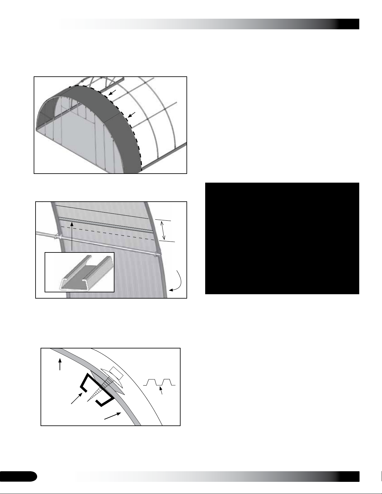
Return to the first seam where two panels overlap and 5.
cut a section of poly-latch U-Channel (#102197) so that
it fits between the rafters.
Upper end of lower panel.
Once the seams for the first run of roof panels are 6.
secured, install the next run of roof panels.
ATTENTION: These panels will overlap the edges
of the installed panels and are secured to the rafter
common to the first set of panels. This is the pattern
throughout the length of the frame.
To more easily reach the rafter to secure this next run
of polycarbonate panels, roll the panel under or over
itself during the installation and unroll the sheet after
securing the edge to the rafter.
Install the horizontal closure strip (104709) between
the panel bottom and the baseboard and continue as
previously described.
Continue installing the corrugated polycarbonate roof 7.
panels and securing the overlap seams as previously
described until all roof panels are installed.
Lower end of upper panel.
U-Channel
(#102197)
Overlap
End
Rafter
NOTE: Position the channel at the seam on the inside
of the greenhouse roof where panels overlap. Install
Tek screws (#FA4482) and washers from the outside,
through the two polycarbonate panels (where they
overlap), and into the poly-latch U-Channel to secure
the seam. Install screws in the valleys of the panels.
Install Tek screws
in the valleys of
the panels.
Polycarbonate
Panel
Valley
U-Channel
Verify that all panels are properly secured and continue 8.
with the ASSEMBLE AND INSTALL SLIDING DOORS
procedure.
Polycarbonate Panel
Secure all overlap seams as you work toward the
other end of the greenhouse. Use four (4) Tek screws
(#FA4482) and four (4) washers for each seam to
secure the roof panels to the U-Channel.
22
Revision date: 07.22.11
Page 23
ASSEMBLE AND INSTALL SLIDING DOORS
CLEARSPAN™ GREENHOUSES
PREPARE THE DOOR FRAMES
The general steps to install the door are as follows:
Assemble the door rollers and attach the brackets to 1.
the door frames.
Assemble each door panel by installing the corrugated 2.
polycarbonate panels and closure strips.
Optional Step: Install door profile (#104548) along door 3.
frame of end wall to cover the gaps created by the
corrugated end wall panels.
Attach the sliding door track to the end wall.4.
Hang the sliding doors in the door track.5.
Install Tek screws (#FA4482) through track to prevent 6.
door from sliding out of the track.
NOTE: The following photos show a door frame without the
polycarbonate panels installed. The installation of the roller
assemblies can occur before or after the panel installation.
If you decide to install the panels before installing the roller
assemblies, you must drill holes through the panel at the
top edge of the door frame to allow the mounting bolts for
the roller assembly to be installed properly.
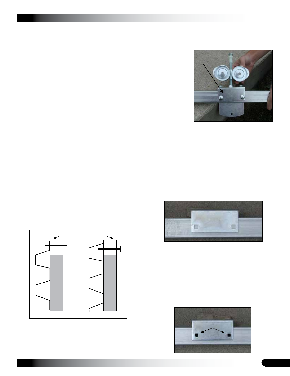
If a rib of the corrugated panel falls where the mounting
bolts are located, nuts of the bolts will fall under the rib.
The roller assembly mounting bolts must be tightened
against the flat surface of the door frame.
Do not install the bolts through a rib of the corrugated
panel.
Locate the two door frames (#102923) and the roller 1.
hardware kits for the top of the door frames.
To prevent
damage to the
end panels,
install the heads
of the carriage
mounting bolts
to the inside of
the door frames.
Photo shows an assembled roller attached to the top of
a door frame. The view is from the inside/backside of
the door. The small angled bracket is installed on the
back of the door or to the inside of the building.
NOTE: Each box includes two roller assemblies for
each door frame.
Position the small angled bracket on the top of the door 2.
frame (with its square holes on the inside surface of the
frame tube) a few inches from the end of the frame (as
desired). Align the holes of the bracket with the center
of the square door frame tube.
Dashed line shows the center of tube.
Small Angled
Bracket
Top of Door Frame
End View of Door
Revision date: 07.22.11
The small angled bracket has square holes to lock the
carriage bolts in place.
The bracket cannot sit tight against the top of the
frame. Space must exist between the frame and the
bracket to allow for the adjusting nut and the bracket
bolts.
Using a 5/16" drill bit, drill the holes through the tube. 3.
The holes must go through the entire tube and must be
straight.
Drill 5/16''
23
Page 24
CLEARSPAN™ GREENHOUSES
ASSEMBLE AND ATTACH SLIDING DOORS (continued)
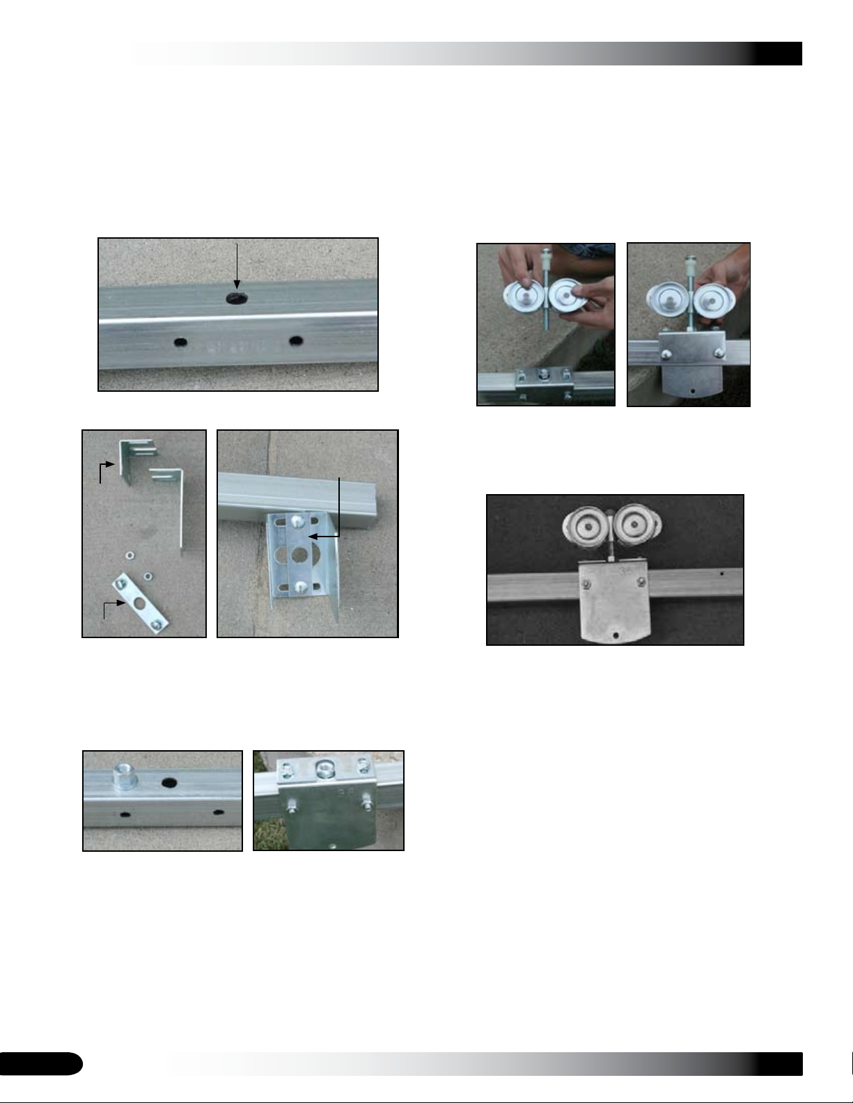
After the holes are drilled, temporarily insert the 4.
carriage bolts through the bracket and tube to hold the
bracket in place and mark the location of the adjusting
bolt hole on the top of the door frame tube.
Using a 1/2" drill bit, drill a hole through the door frame 5.
tube. The hole allows the adjusting bolt of the roller
assembly to extend through the tube if needed.
Assemble the flat plate and brackets as shown below. 6.
Flat Plate is placed on top
of the door frame with bolts
pointing up to receive the
nuts.
Small
Angled
Bracket
Adjust the flat plate and brackets to align the adjusting 8.
nut with the pre-drilled 1/2'' hole and tighten bolts.
NOTE: The adjusting nut must turn freely between
the brackets and the top of the door frame. Tighten all
bolts.
Install the adjusting bolt and roller assembly. Position 9.
the notch of the roller assembly up and away from the
door.
Repeat the steps to assemble and attach the remaining 10.
roller assembly to the door frame. Photo below shows
the attached roller assembly as seen from the outside
or front.
Flat Plate
Do not tighten the small bolts at this time. You will need
to adjust the brackets when the rollers are installed.
Place the adjusting nut on the door frame and set the 7.
assembled brackets and flat plate over the nut.
NOTE: Assembly is shown looking from the front or
outside. Insert the mounting carriage bolts for the
brackets from the back to prevent damage to the
polycarbonate panels on the end wall when the door is
used.
Brackets must be assembled as shown so that the
holes in the brackets are aligned.
After attaching the roller assemblies, turn the door 11.
frame on its side and drill a hole in the bottom of the
frame tube. (This hole will allow water drain from inside
the door frame if it finds its way through the adjusting
hole at the top of the frame.
NOTE: Each box includes two (2) roller assemblies for
each door frame.
Repeat the steps to assemble and attach the remaining 12.
roller assemblies.
24
Revision date: 07.22.11
Page 25
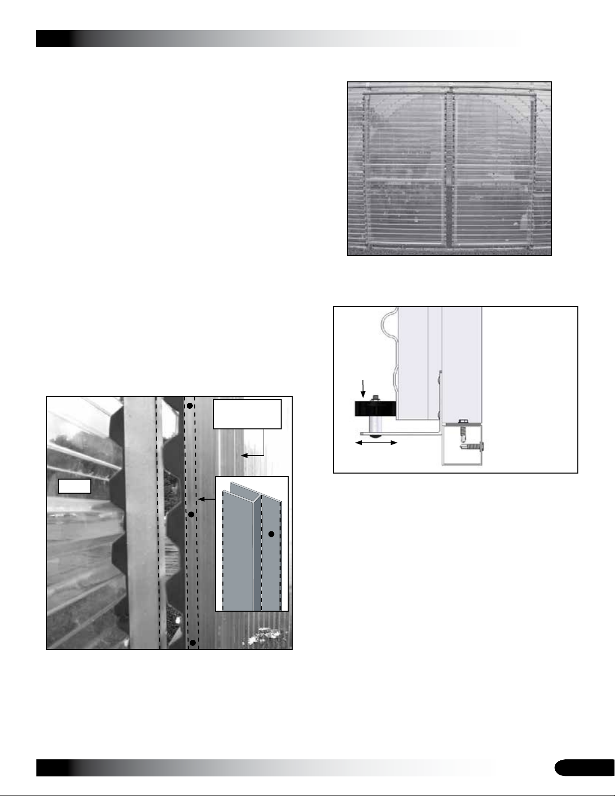
ASSEMBLE AND ATTACH SLIDING DOORS (continued)
ASSEMBLE THE SLIDING DOOR
After attaching the rollers to the top of the doors, install 1.
the corrugated polycarbonate panel on the doors using
Tek screws (#FA4482) and washers (#102921).
NOTE: The horizontal closure strips are used under
the panels along the edges to seal the corrugated
openings when the panels are installed with the ribs in
the horizontal position as shown in the photo (right).
Each door is covered using one 50" x 8' 2" panel. DO
NOT cut 12' panels to cover the doors.
Install the 104548 profile along the end wall door frame 2.
as shown in the following photos.
ATTENTION: The installation of the 104548 profile is
an optional step for those who want to cap the end of
the corrugated end panels at the door opening. Use
Tek screws to secure the profile to the end wall framing.
Photo below shows end wall without installed profile.
Dashed line shows where to install profile to cover
the valleys of corrugated end panels. View is from the
inside of the frame looking at the point where the door
meets the door frame of the end wall.
End Wall
Frame Tube
CLEARSPAN™ GREENHOUSES
Photo below shows the assembled doors and the
corrugated polycarbonate panels.
Using the lower roller assembly as a guide, place one 3.
assembled door into position and rest its bottom edge
on the lower roller assembly as shown below.
Side view of the
door showing the
door frame and
stay roller.
Stay Roller
End
Wall
Frame
Door
Frame
Door
Adjust Stay Roller
as needed.
With the first door in position, use blocks to level the 4.
door and set the second assembled door in place.
Level the second door and temporarily secure both 5.
doors in place so they do not tip to the inside or outside
of the greenhouse.
Using the rollers as guides, mark the location on the 6.
end wall for the sliding door track.
NOTE: Be sure to account for the distance between the
top of the door frame and the roller assembly. You must
be able to adjust the door (up or down) once the track
is installed so that the doors are centered in the rough
door opening.
Use the lower roller assembly as a guide. The final
adjustment for the door will lift the door 1/4" to 1/2" off
the angled brackets of the lower roller assemblies.
Revision date: 07.22.11
25
Page 26
CLEARSPAN™ GREENHOUSES
ASSEMBLE AND ATTACH SLIDING DOORS (continued)
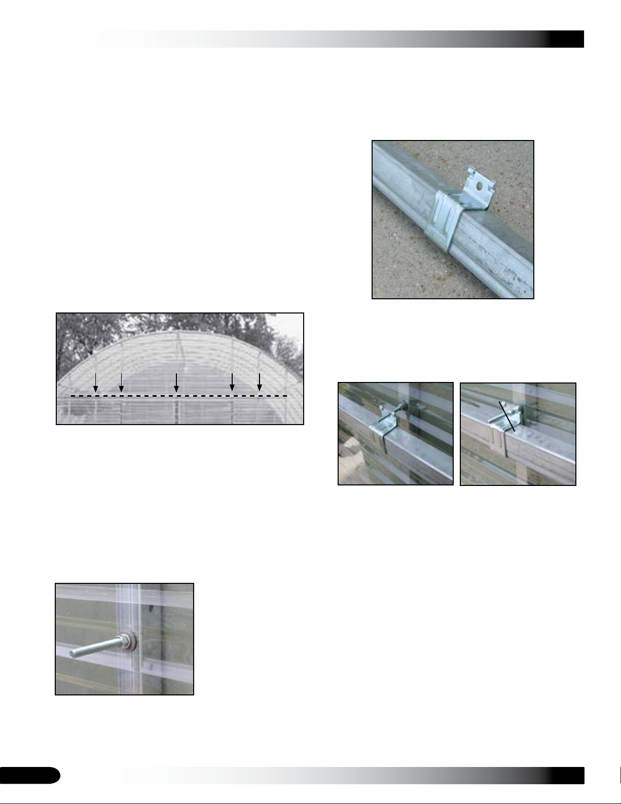
Verify that the marks for the sliding door track are level 7.
and attach the two sections of door track to the end
wall frame.
NOTE: The track must be level for the doors to function
properly.
INSTALL SLIDING DOORS
Complete the following steps to properly attach the sliding
door track mounts to the end wall frame of the greenhouse.
Locate the 3/8" x 4" carriage bolts and related nuts and 1.
washers used to secure the track brackets to the end
wall framing.
After identifying and marking the desired height of the 2.
door track on the end wall, determine the locations of
the track brackets.
Repeat the steps to install the remaining sliding track 5.
mounting bolts. All mounting bolts must be installed at
the same height on the end wall frame so that the track
is level.
After installing the mounting bolts, slide the two track 6.
mounting brackets onto the sliding door track.
Align the brackets with the mounting bolts and install a 7.
flat washer, lock washer, and a nut.
The dashed line above represents the sliding door
track. The arrows show where to attach the track
brackets to the end wall framing.
Drill a 3/8" hole through the corrugated polycarbonate 3.
panel and through the vertical end wall frame tube.
The hole must be level to mount the bracket and track
properly.
Insert a 3/8" carriage bolts through a hole from inside 4.
the building and tap it with a hammer to set it tight
against the end wall frame member.
Install a flat washer,
lock washer and nut to
secure the mounting
bolt to the end wall
frame.
Verify that the track is level and flush to the inside edge 8.
of the end rafter and tighten the 3/8" nuts. The carriage
bolts can be trimmed if desired.
Cut if desired
NOTE: The center track mounting bracket will cover
the joint where the separate track sections meet at the
center of the end wall.
After securing the track to the end wall frame, lift one 9.
door up and into place and insert the rollers into the
track.
Repeat the step to install the second door into the 10.
track.
Slide both doors to the center of the door opening to 11.
the closed position and adjust as needed to level the
doors so they meet evenly at the center.
Adjust the lower stay rollers as needed.12.
26
Revision date: 07.22.11
Page 27
CLEARSPAN™ GREENHOUSES
ASSEMBLE AND ATTACH SLIDING DOORS (continued) SHELTER CARE AND MAINTENANCE
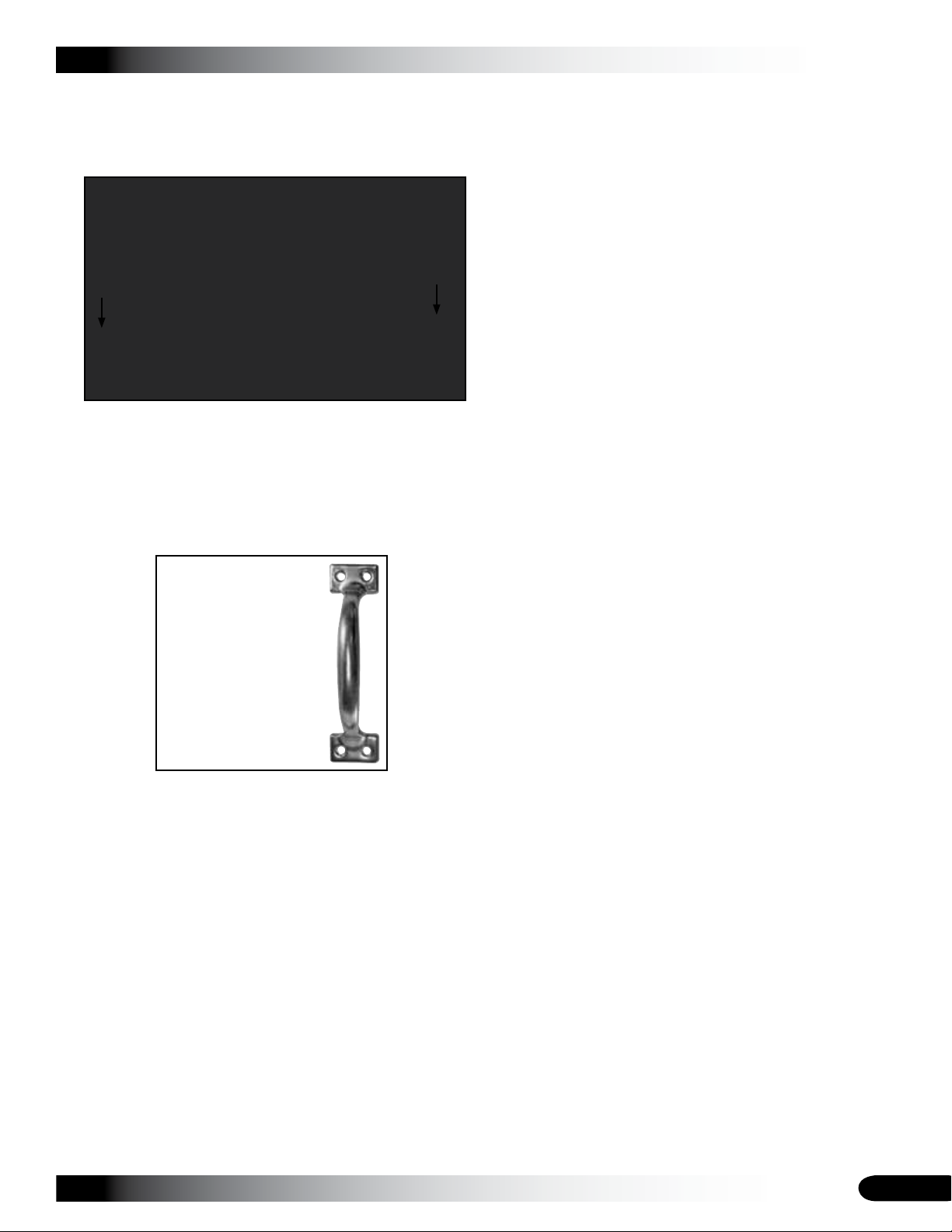
After adjustments are made, slide one door to its open 13.
position and install two Tek screws through the door
track to prevent the door from sliding out of the track.
Arrows show the locations of Tek screws (two at each
end) used as door stops. Tek screws are installed
through the front of the door track.
Repeat the previous step for the remaining door.14.
Install the door handle in the desired location. Door 15.
handle is attached using Tek screws.
Use the FA4482B
Tek screws to secure
handle through the
polycarbonate panel
and into the door
frame.
Proper care and maintenance of the shelter is important.
Check the following items periodically to properly maintain
the shelter:
Regularly check the polycarbonate panels to see •
that these are secure and in good condition. Replace
damaged panels if needed.
Check connections and all fasteners to verify that they •
remain tight.
Do not climb or stand on the greenhouse at anytime. •
(See the ridge cap installation notes.)
Inspect the anchoring system to verify that all •
components remain tight and in good condition.
Remove debris and objects that can accumulate on the •
greenhouse. Use tools that will not damage the cover
when removing debris.
Remove snow to prevent excess accumulation. Use •
tools that will not damage the polycarbonate panels
when removing snow.
Check the contents of the shelter to verify that nothing •
is touching the polycarbonate panels that could cause
damage.
If the greenhouse is moved, inspect all parts and •
connections before it is reassembled.
Depending on the contents, construction of the shelter, •
shelter materials, and shelter location, the potential for
condensation exists. ClearSpan™ offers several items
that can be used to alleviate a condensation condition.
Please contact a ClearSpan™ representative for
additional information.
Continue by reading the 16. CARE AND MAINTENANCE
information that follows.
Revision date: 07.22.11
For replacement or missing parts, call 1-800-245-9881 •
for assistance.
NOTE: With the exception of Truss Arch buildings,
ClearSpan™ shelters and greenhouses do not have any
tested loading criteria.
27
Page 28
CLEARSPAN™ GREENHOUSES
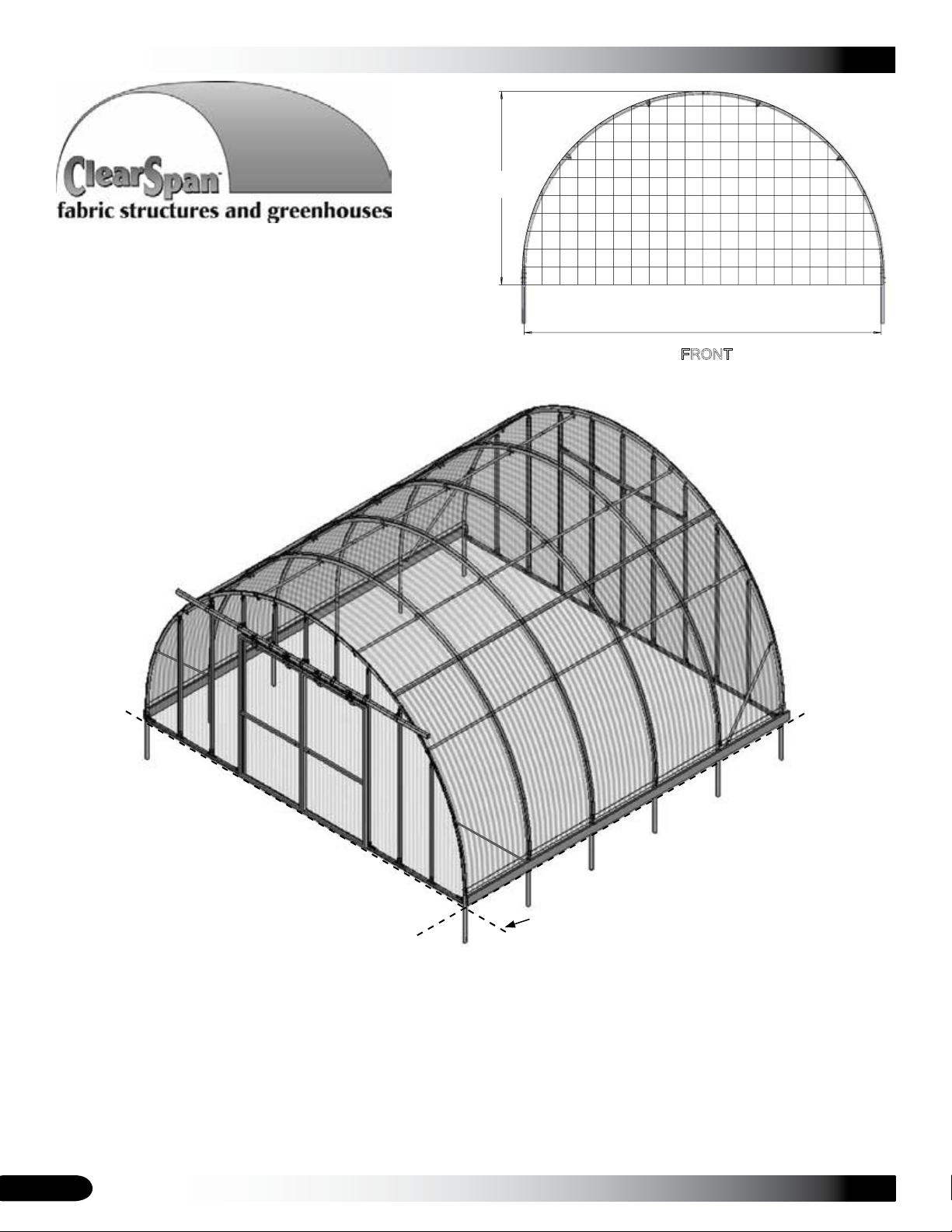
20'-0"
Width
10'-10"
Height
Grid Represents 12" Squares
FRONT
QUICK START GUIDE
20' Round Style Greenhouse
28
Ground Level
Frame shown may differ in length from actual frame.
Revision date: 07.22.11
Page 29
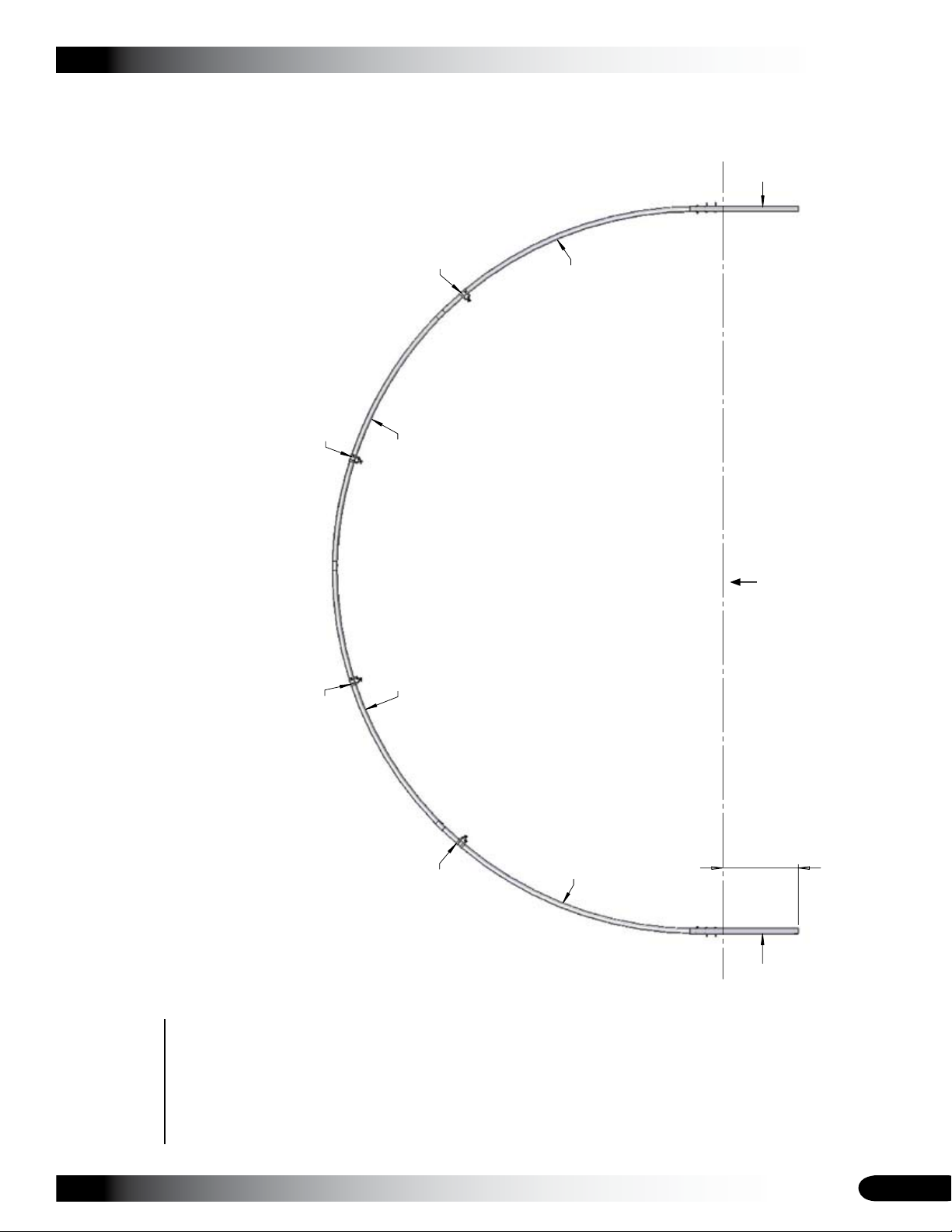
2'-1"
102675
Ground Post
102675
Ground Post
20R1601D
Rafter Pos. 1
20R1601
Rafter Pos. 2
20R1602
Rafter Pos. 3
20R1601D
Rafter Pos. 1
Purlin Connection
See Connection Note
Purlin Connection
See Connection Note
Purlin Connection
See Connection Note
Purlin Connection
See Connection Note
Purlin connected to end rafters using
102856 clamp
Purlin connected to mid rafters using
102548 connector
CLEARSPAN™ GREENHOUSES
FRONT PROFILE
Ground Level
Revision date: 07.22.11
29
Page 30
CLEARSPAN™ GREENHOUSES
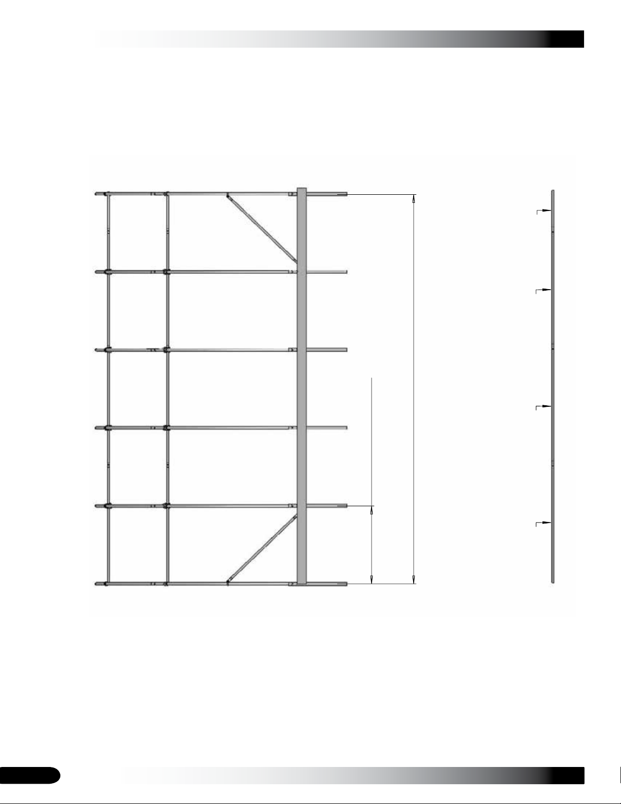
131S075
131S075
131S075
131P0255
Baseboards Supplied
by Customer
Purlin Run
20'-0"
Shelter Length
4'-0" Rafter Spacing
SIDE PROFILE - 106185
30
Revision date: 07.22.11
Page 31
CLEARSPAN™ GREENHOUSES
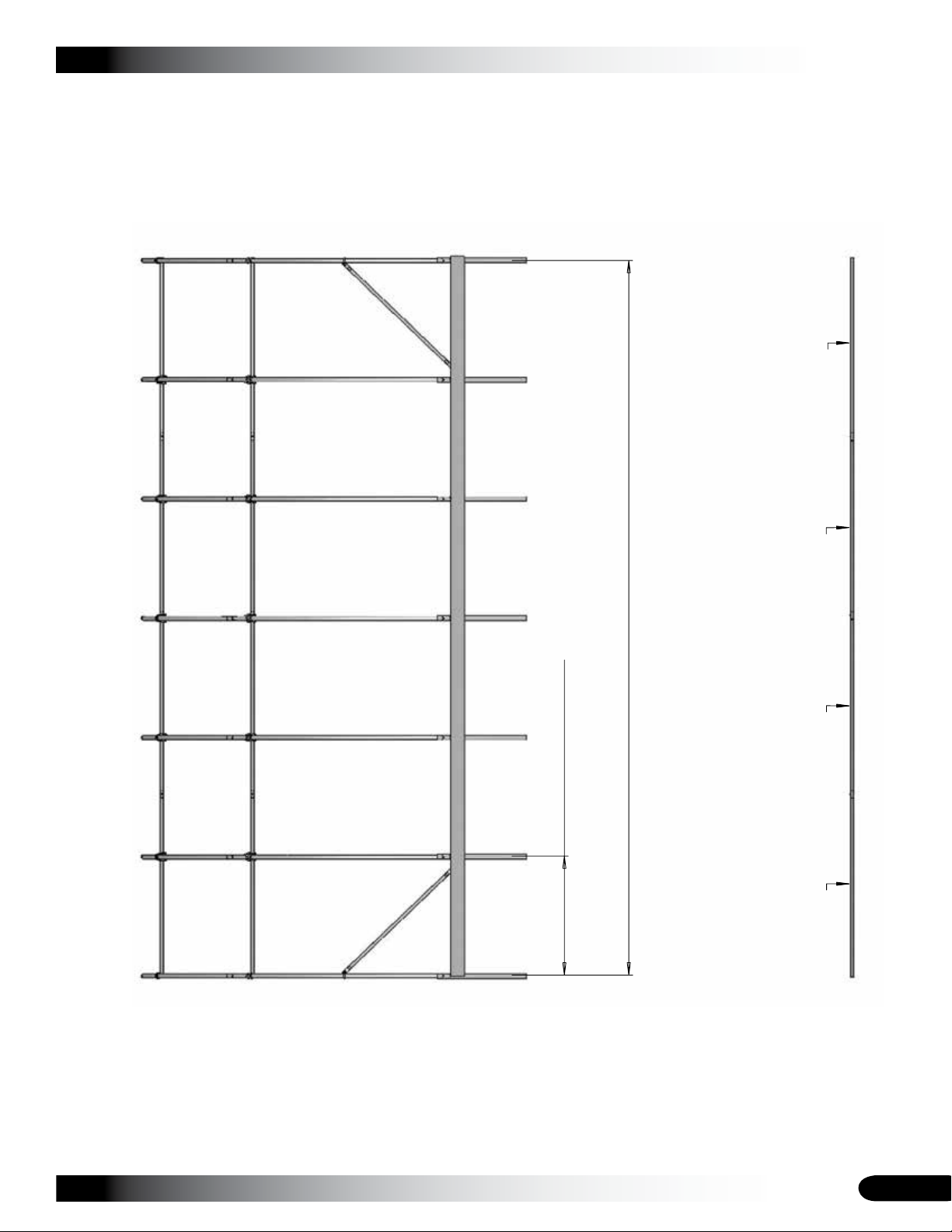
Baseboards Supplied
by Customer
Purlin Run
24'-0"
Shelter Length
4'-0" Rafter Spacing
131S075
131S075
131S075
131P0735
SIDE PROFILE - 106186
Revision date: 07.22.11
31
Page 32
CLEARSPAN™ GREENHOUSES
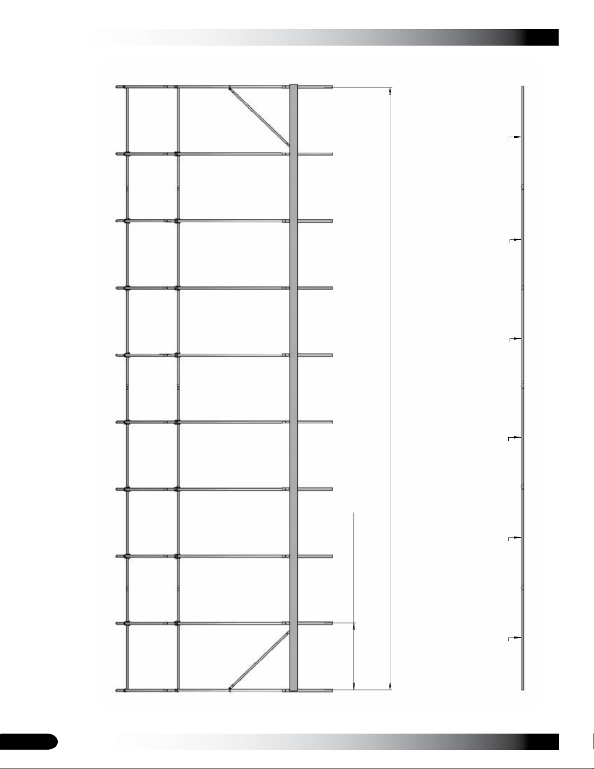
131S075
131S075
131S075
131P0735
131S075 131S075
Baseboards Supplied
by Customer
Purlin Run
36'-0"
Shelter Length
4'-0" Rafter Spacing
SIDE PROFILE - 106187
32
Revision date: 07.22.11
Page 33
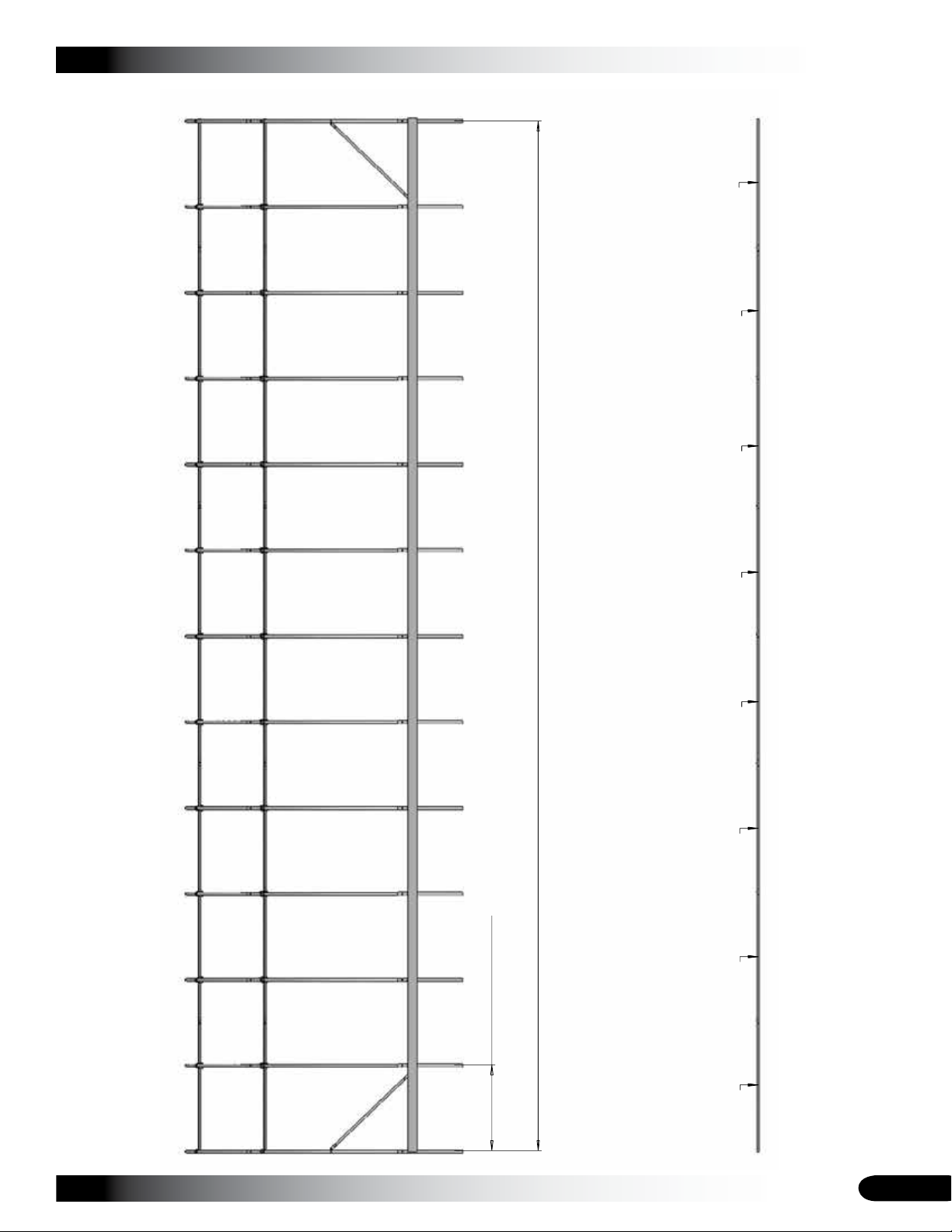
131S075
131S075
131S075 131S075 131S075
131P0735
131S075 131S075
Baseboards Supplied
by Customer
Purlin Run
48'-0"
Shelter Length
4'-0" Rafter Spacing
CLEARSPAN™ GREENHOUSES
SIDE PROFILE - 106188
Revision date: 07.22.11
33
Page 34
CLEARSPAN™ GREENHOUSES
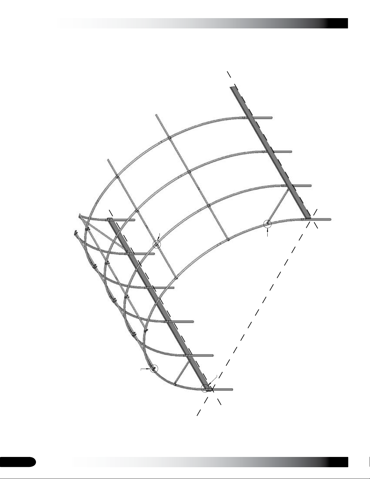
Note: Baseboards are supplied by the customer.
Connection
View 1
Purlin-Mid Rafter
Connection
View 3
Rafter-Strut
Connection
View 2
Rafter - Ground Post
Connection
View 4
CONNECTIONS
Ground Level
34
Revision date: 07.22.11
Page 35
CLEARSPAN™ GREENHOUSES
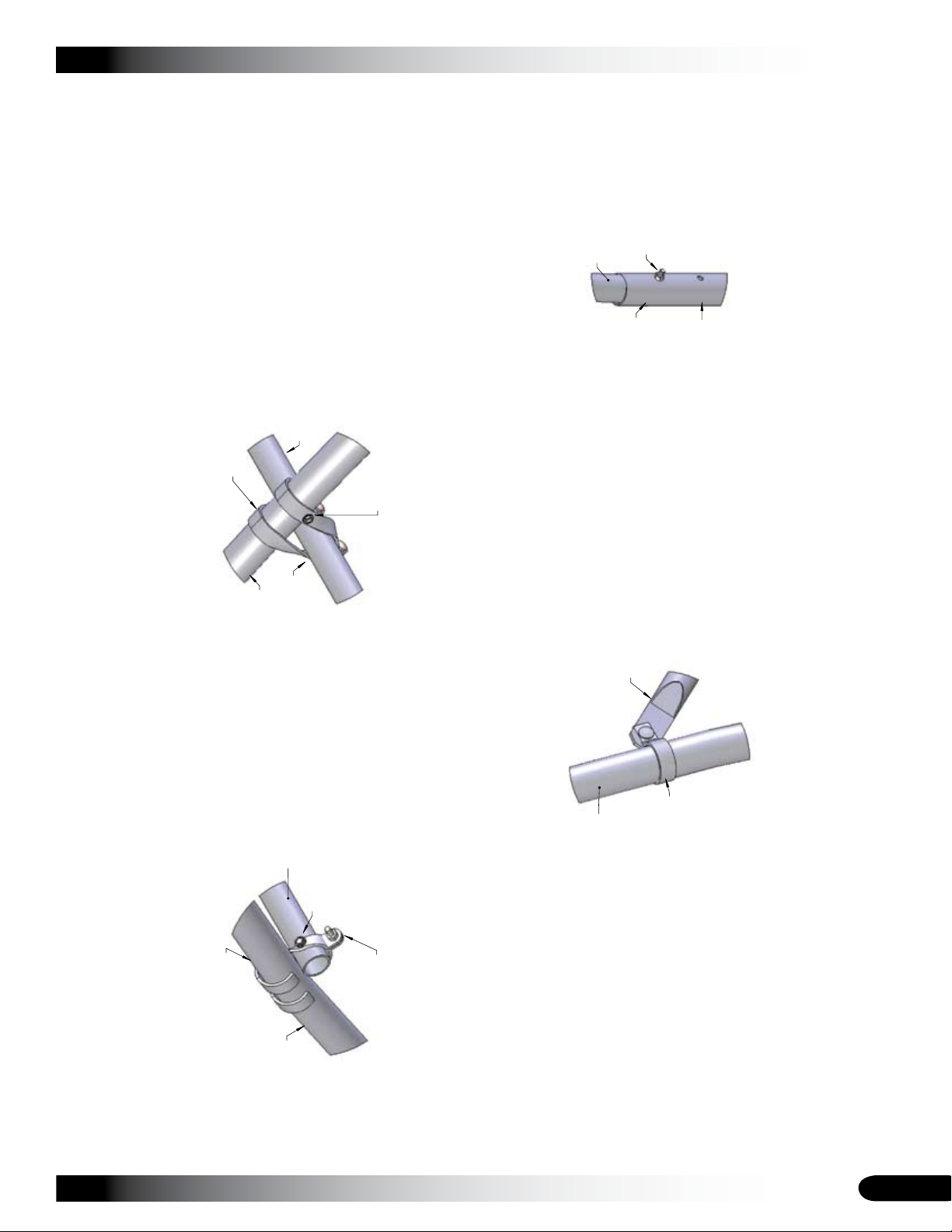
VIEW 1
PURLIN - END RAFTER
Purlin
Purlin End Clamp
Tek Screw
Through clamp into purlin
(*another tek screw used on
back through clamp into rafter)
Tek Screw*
VIEW 2
RAFTER - STRUT
VIEW 4
RAFTER - GROUND POST
Strut
Rafter
1.66 Band Clamp
Ground Post
Rafter
5/16" Nut
5/16"x2 1/2" Bolt
VIEW 3
PURLIN - MID RAFTER
Rafter
Tek Screw
Through clamp into rafter.
(*another tek screw used to
secure clamp to purlin)
Purlin Cross
Connector
Purlin
Tek Screw*
CONNECTION - FRAME DETAILS
Revision date: 07.22.11
35
Page 36
CLEARSPAN™ GREENHOUSES
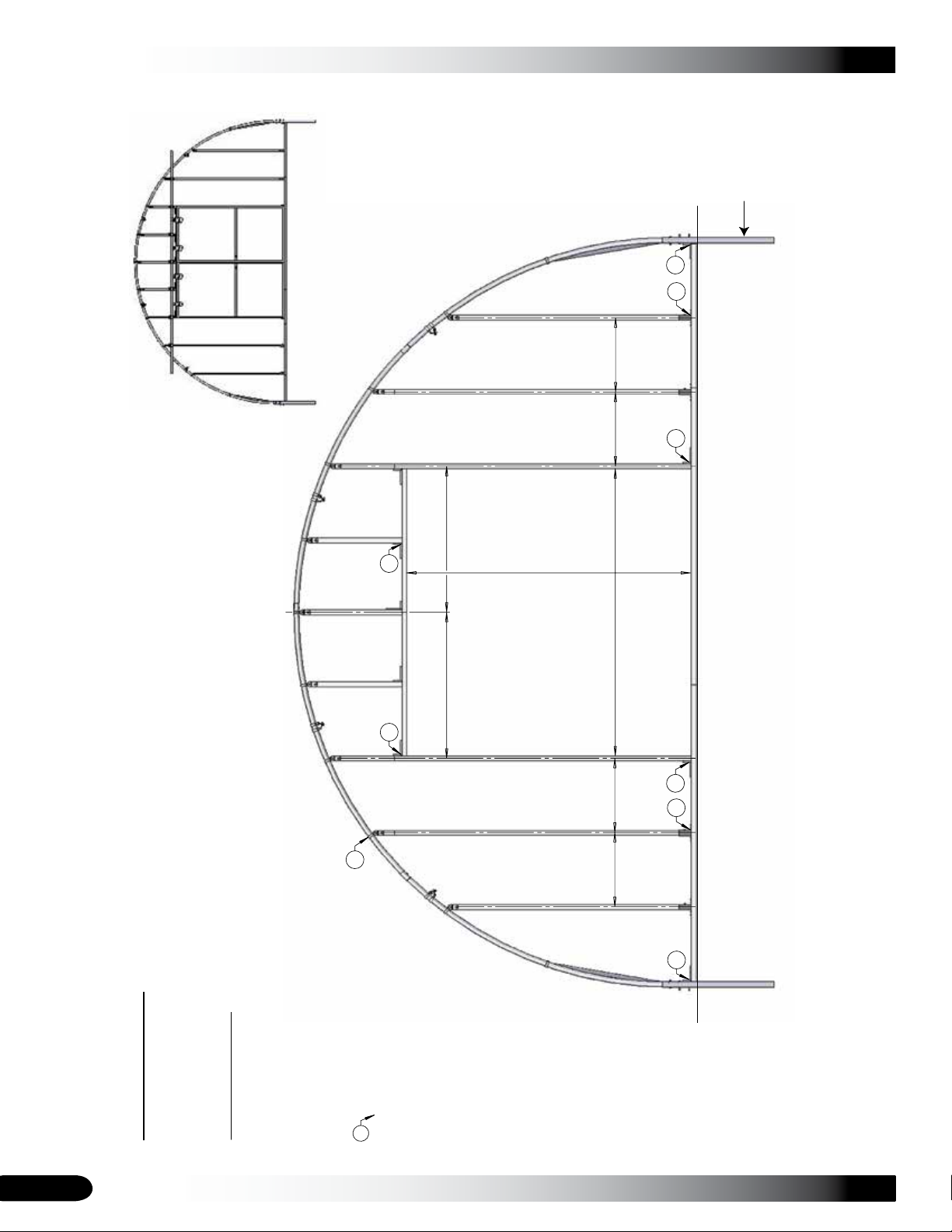
24"
C
L
C
L
24"24"
C
L
47 1/4"
C
L
47 1/4"
C
L
24"
C
L
End Frame Detail Guide
End Framing-Rafter, View 11.
QH1330 Bracket, View 22.
104624 1-Way/Plate, View 33.
S.F.
S.F.
P.C.
P.C.-N.C.
P.C.-N.C.
S.F.-N.C.
S.F.-C.
S.F.-C.
S.F.-N.C.
P.C.-C.
P.C.
P.C.
P.C.-C.
P.C.-N.C.
P.C.
P.C.
1
2
2
2
2
2
2
3
3
Symbol & Abbv. Key
S.F. Swaged, Full Piece
P.C. Plain, Cut from Swaged
N.C. Non Critical Location
C. Critical Location
I.D. Inside Dimension
C
L
Center Line Dimension
Balloon: Number reflects
detail. See Detail Guide.
Note: Balloons only point out several
instances of each detail; applications
may apply elsewhere in assembly.
All end framing tubes are cut from or are full (102897) 1 1/2"x1 1/2" swaged square tubing.
Non critical verticals are spaced 24" on center working outwards from the door. However,
these verticals can be spaced differently for the framing of greenhouse accessories. For
the framing of accessories, check for rough opening and space accordingly.
Critical verticals can not be spaced differently because of door opening or Polycarb attachment.
Height of verticals depends on location. Measure location before cutting materials.
Center of
Shelter
P.C.-N.C.
#
93" I.D.
89" I.D.
Ground Level
Ground Post
View Shown with Door
END FRAME DIAGRAM - FRONT VIEW
36
Revision date: 07.22.11
Page 37
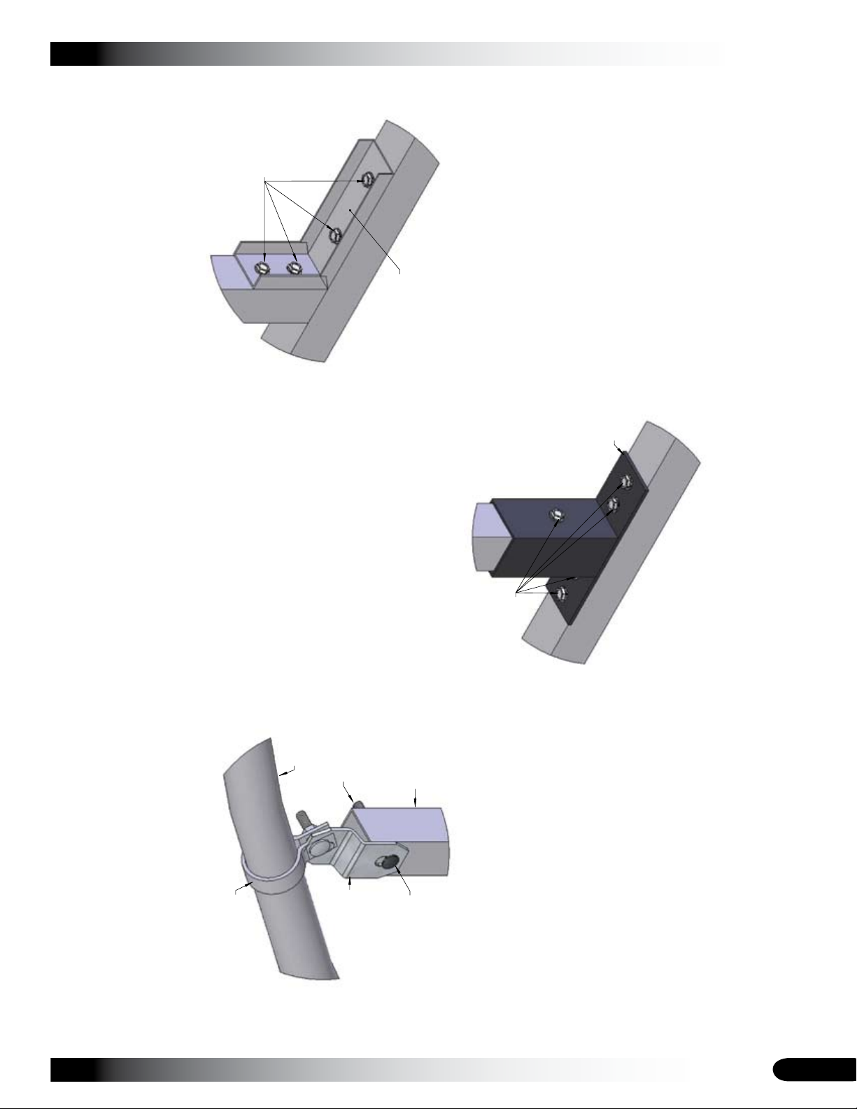
VIEW 1
END FRAME - RAFTER
1.66 Band Clamp
Rafter
104074 Bracket
Vertical Assembly
5/16"x2 1/2"
Carr. Bolt
5/16" Nut
VIEW 2
END FRAME - QH1330
QH1330
Tek Screws
VIEW 3
END FRAME - 104624
104624
Tek Screws
CLEARSPAN™ GREENHOUSES
CONNECTIONS - END FRAMING
Revision date: 07.22.11
37
Page 38
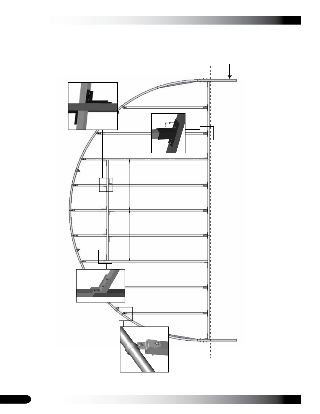
CLEARSPAN™ GREENHOUSES
47 1/2" 47 1/2"
Symbol & Abbv. Key
S.F. Swaged, Full Piece
P.C. Plain, Cut from Swaged
N.C. Non Critical Location
C. Critical Location
C
L
C
L
C
L
Center Line Dimension
All end framing tubes are cut from or are full (102897) 1 1/2"x1 1/2" swaged square tubing.
Non critical verticals are spaced 24" on center working outwards from the door. However,
these verticals can be spaced differently for the framing of greenhouse accessories. For
the framing of accessories, check for rough opening and space accordingly.
Critical verticals can not be spaced differently because of door opening or Polycarb attachment.
Height of verticals depends on location. Measure location before cutting materials.
P.C.-N.C.
P.C.-C.
P.C.-N.C.
Center of
Shelter
Back end framing is the same as the front end framing with
the addition of 3 verticals in the door opening.
Ground Level
Ground Post
END FRAME DIAGRAM - BACK VIEW
38
Revision date: 07.22.11
Page 39
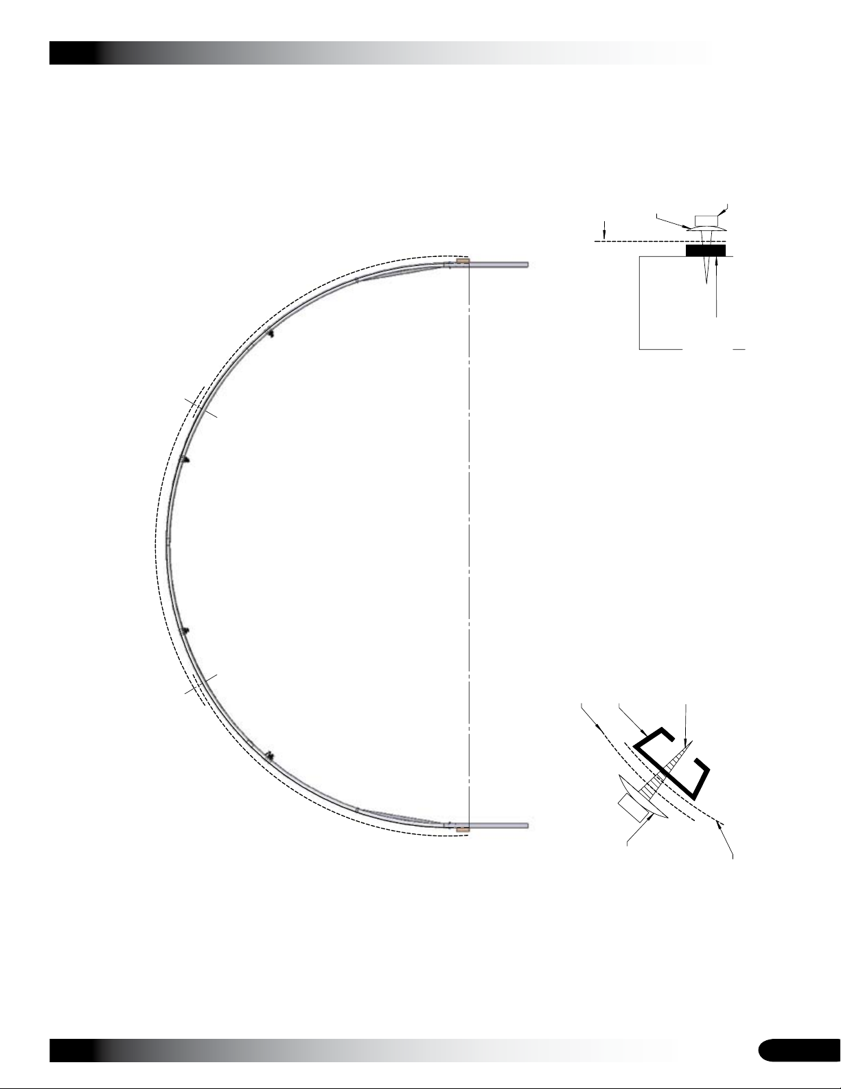
CLEARSPAN™ GREENHOUSES
102197 Trimmed to
fit between rafters
-Used as backing for the Tek
Screw to "bite" creating a
tight seal between sheets.
POLY SPLICE
Upper poly sheet
-Upper sheets always
overlap lower sheets.
Lower poly sheet
-Lower sheets always get
overlapped by upper sheets.
Tek Screw
Neo Bonded Washer
BASE SEAL
Base Board
Corr. Poly Sheet
Neo Bonded
Washer
Tek Screw
104709 Closure Strip
-Creates seal between
Polycarbonate and base board.
4'x 12'
4'x 12' 4'x 12'
Poly
Splice
Poly
Splice
Base
Seal
Base
Seal
MAIN COVER DETAILS
Revision date: 07.22.11
39
Page 40
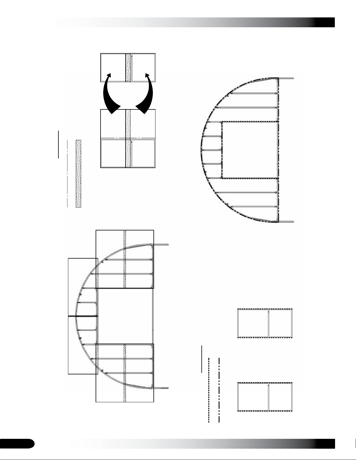
CLEARSPAN™ GREENHOUSES
Front End Frame
Door 1
Door 2
Front End Frame
Door 2
Door 1
Trimmed Poly to be used elsewhere
Area of overlapping sheets
-Upper sheets always overlap lower sheets.
Symbol Key
Symbol Key
104709 - Corr. Closure Strip
104710 - Flat Closure Strip
CORRUGATED POLYCARBONATE LAYOUT
Excess
Excess
POLYCARBONATE CLOSURE STRIP LAYOUT
4'x 8'
4'x 8'
4'x 8'
4'x 8'
4'x 8'
4'x 8'
4'x 8'
4'x 8'
40
POLYCARBONATE PANELS - FRONT VIEW
Revision date: 07.22.11
Page 41
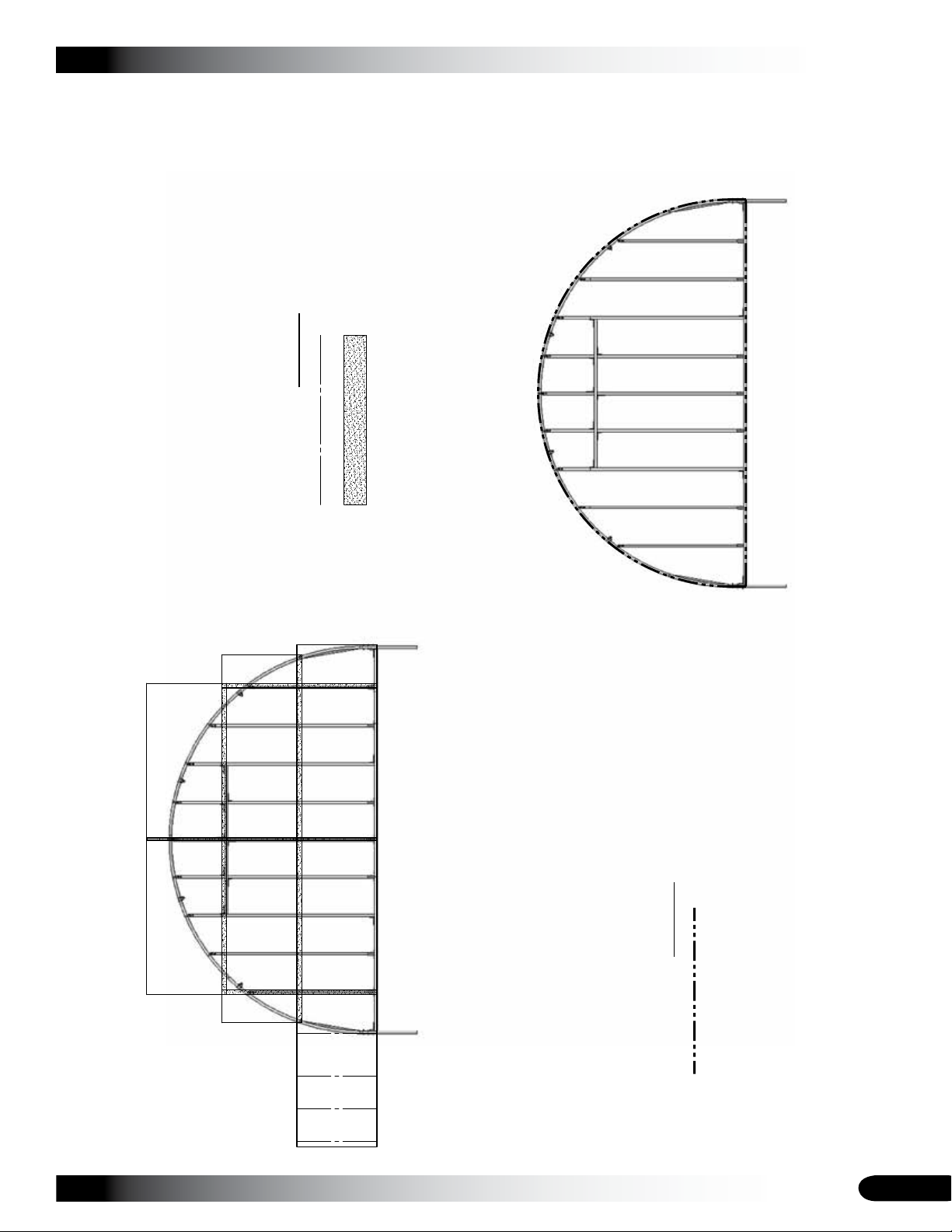
POLYCARBONATE CLOSURE STRIP LAYOUT
CORRUGATED POLYCARBONATE LAYOUT
Excess
A
Use A
Here
Use B
Here
Use C
Here
4'x 8'
4'x 8'
4'x 8'
4'x 8'
4'x 8'
4'x 8'
4'x 8'
Back End Frame
Back End Frame
Trimmed Poly to be used elsewhere
Area of overlapping sheets
-Higher sheets always laps over lower sheets
Symbol Key
Symbol Key
104710 - Flat Closure Strip
Excess B
Excess C
CLEARSPAN™ GREENHOUSES
POLYCARBONATE PANELS - BACK VIEW
Revision date: 07.22.11
41
 Loading...