

CLEARSPAN™ END WALL FRAMING KITS
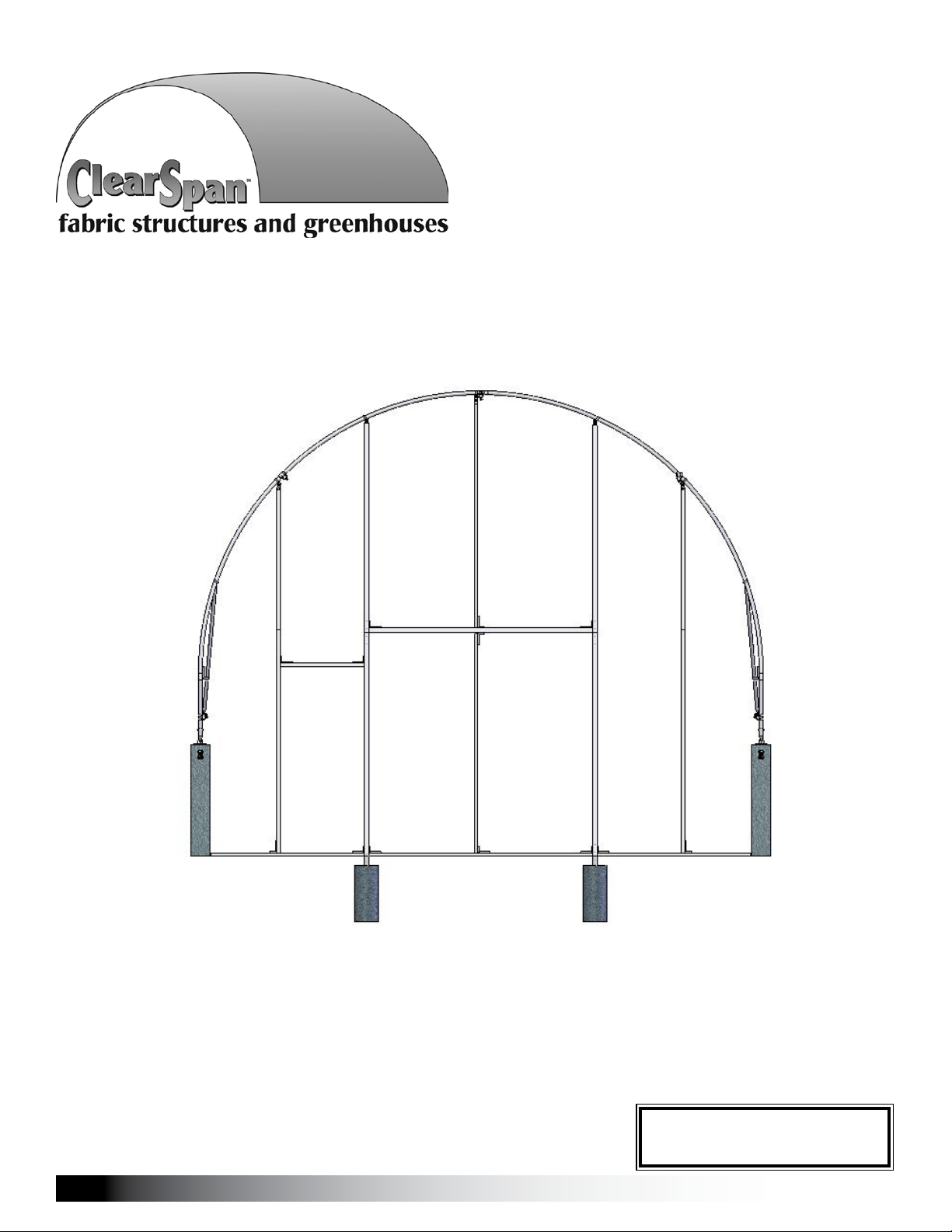
ClearSpan™ End Frame Kit
20' Wide x 16' High
Diagram shows the end frame kit for an end wall without a door. (Door and end panel are
purchased separately.) Rafter and struts shown in the above diagram are not included with kit.
©2010 ClearSpan™
All Rights Reserved. Reproduction
is prohibited without permission.
Revision date: 09.13.10
STK#
106627 End Frame Kit
1

CLEARSPAN™ END WALL FRAMING KITS
ASSEMBLY PROCEDURE
Following the instructions as presented will help ensure the
proper assembly of your end wall. The steps outlining the
assembly process are as follows:
Verify that all parts are included in the shipment. Notify 1.
Customer Service for questions or concerns.
YOU MUST READ THIS DOCUMENT BEFORE YOU
BEGIN TO ASSEMBLE THE END WALL KIT.
Thank you for purchasing this ClearSpan™ End Frame Kit.
When properly assembled and maintained, this product will
provide years of reliable service. These instructions include
helpful hints and important information needed to safely
assemble and properly maintain the end wall. Please read
these instructions before you begin.
If you have any questions during the assembly, contact
Customer Service for assistance.
SAFETY PRECAUTIONS
Wear eye protection.•
Wear head protection.•
Wear gloves when handling metal tubes.•
Use a portable GFCI (Ground Fault Circuit Interrupter) •
when working with power tools and cords.
Do not climb on the shelter or framing during or after •
construction.
Do not occupy the shelter during high winds, •
tornadoes, or hurricanes.
Provide adequate ventilation if the structure is •
enclosed.
Do not store hazardous materials in the shelter.•
Provide proper ingress and egress to prevent •
entrapment.
WARNING: The individuals assembling this end
frame are responsible for designing and furnishing all
temporary bracing, shoring and support needed during
the assembly process. For safety reasons, those who
are not familiar with recognized construction methods
and techniques must seek the help of a qualified
contractor.
Read these instructions, the Must Read document, and 2.
all additional documentation included with the shipment
before you begin assembling the end wall.
Gather the tools, bracing, ladders (and lifts), and 3.
assistance needed to assemble the end frame.
Check the weather 4. before you install the end frame
panel (if equipped). Do not install end panels on a
windy or stormy day.
Assemble the end wall frame. 5.
Read the care and maintenance information at the end 6.
of these instructions.
Complete and return all warranty information as 7.
instructed (if included).
REQUIRED TOOLS
The following list identifies the main tools needed to
assemble the end wall. Additional tools and supports may
be needed depending on the structure, location, and
application.
Tape measure or measuring device•
Fine point marker to mark the location on tubing.•
Variable speed drill and impact driver (cordless with •
extra batteries works best)
Metal file and metal-cutting saw•
Wrenches and impact socket set•
Scissors or utility knife•
Hammers, gloves and eye protection•
Adjustable pliers and self-locking pliers•
Ladders, work platforms, and other machinery for lifting •
designed to work safely at the height of the building
and end wall.
ATTENTION: Consult the services of a qualified,
professional contractor if you are not familiar with the
construction of similar frame structures.
2
Revision date: 09.13.10

UNPACK AND IDENTIFY PARTS
CLEARSPAN™ END WALL FRAMING KITS
The following steps will ensure that you have all the
necessary parts before you begin to assemble the end wall.
Unpack the contents of the shipment and place where 1.
you can easily inventory the parts. Refer to the Bill of
Materials/Spec Sheets.
Verify that all parts listed on the Bill of Materials/Spec 2.
Sheets are present. If anything is missing or you have
questions, consult the parts guide on the next page
and all shelter diagrams for clarification, or contact
customer service.
NOTE: At this time, you do not need to open the plastic
bags containing smaller parts such as fasteners and
clamps.
QUICK START GUIDE
For a quick overview of the end wall and its components,
consult the Quick Start Guide at the back of these
instructions.
Optional End Panel Installation (additional purchase)
In addition to the end frame installation steps, these
instructions describe installing an optional end panel.
(Additional purchase required.)
Space below is reserved for customer notes.
The components used to install the optional end panel are
also described and shown during the procedure. Some
components may differ from what is shown.
Contact your sale representative to purchase an end panel
with end panel installation kit if desired.
ATTENTION: Some of these instructions may not apply
to your end wall and shelter. It is the customer's or
contractor's responsibility to adapt these instructions as
needed during the construction process.
These end wall kits are designed to attach to buildings
with a specific rafter pipe dimension. Differences in
pipe dimensions may require the purchase of additional
components. If you are securing the end frame kit to an
existing structure, verify that you have the required clamps
to complete the installation. May not apply to your building.
Revision date: 09.13.10
3
CLEARSPAN™ END WALL FRAMING KITS
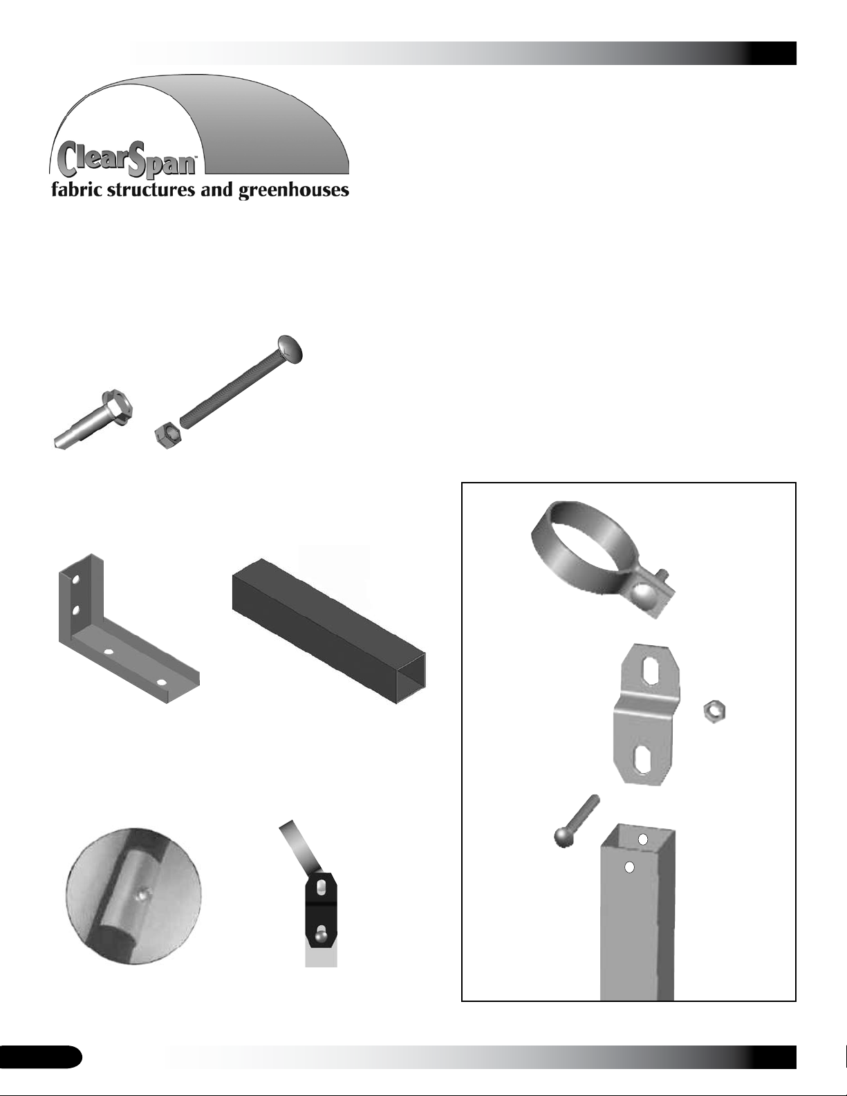
The following graphics and photos will help you identify the
different parts. (Some parts are not shown.)
FA4482B
Tek Screw
QH1330
Angled Bracket
FALB32B & FAH320B
Nut and Carriage Bolt
1.75" x 1.75" Square Tube
104075
Band Clamp
FALB32B
5/16" Nut
104074
FAH320B
2-1/2"
Carriage
Bolt
4
CC6213
Fabric Clip
104074
Square-to-Round Tube
Bracket
End Frame
Square Tube
End Frame-to-Rafter Exploded View
Revision date: 09.13.10
OVERVIEW
This section describes assembling your end frame kit. For
details, please see section "Assembling the End Frame Kit
Components." See illustration below to identify main parts
of end frame kit.
Locate the required parts for each assembly procedure.1.
Prepare and secure posts for the door framing. 2.
(See Front Profile diagrams.)
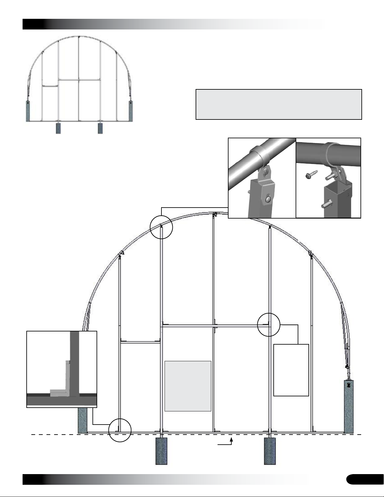
CLEARSPAN™ END WALL FRAMING KITS
ClearSpan™
End Frame Kit
ATTENTION: End frame spacing depends on the door sizes
and may differ from what is shown in these diagrams. Consult
the Front Profile diagrams in the Quick Start section for pipe
identifications and locations.
Assemble and attach all end 3.
framing.
Prepare and attach end 4.
panel (if equipped).
NOTE: Rafter and struts
are not included with kit.
ATTENTION: If
you are installing
an overhead
door, do not
attach framing
within the door
opening.
Secure the band clamp
to the rafter using a Tek
screws as shown.
The 2" x 2"
door frame
tubes are
joined using
a 104075
insert and
Tek screws.
Revision date: 09.13.10
Ground Level
5
CLEARSPAN™ END WALL FRAMING KITS
ASSEMBLING THE END FRAME KIT COMPONENTS
Sample Frame
Consult the end wall diagrams in the Quick Start section of
these instructions before you begin.
ATTENTION: If the main cover is installed, loosen the two
(2) main cover bonnet ratchets at the end of the shelter
where the end wall will be installed. If an end panel is to
be installed, remove the ratchets to install the end panel
frame. The ratchets are reattached after the end frame is
installed.
Assistance is required to assemble the end wall. Lifts
designed to reach the top of the end rafter are also needed.
Consult a qualified construction professional if you are not
familiar with the construction of similar frame structures.
Install the Ground Posts for Door Frame (Jambs)
Ground Level
ATTENTION: If you are installing an overhead door, do not
attach framing within the door opening.
The following steps describe one way to set the ground posts for the door frame tubes.
At ground level, measure 1. between the legs of the end rafter to locate the center of the end wall. Use a plumb line to
identify the center of the overhead rafter and mark that location on the ground as well.
NOTE: Marking the center of the end wall allows multiple measurements to be made as needed.
Using the dimensions on the Front Profile diagrams, locate the positions of the2. door jambs for the door (if equipped).
The width of the door determines the frame dimensions for the door opening. Consult the documentation sent with the
door for the correct spacing of the door jambs.
Dig a 12" diameter hole 3. at the locations found in previous step to a depth that is below the geographic frost line.
Add concrete to the hole. Concrete should remain 1" to 2" below ground level so that it does not interfere with 4.
construction and installation of other end wall components.
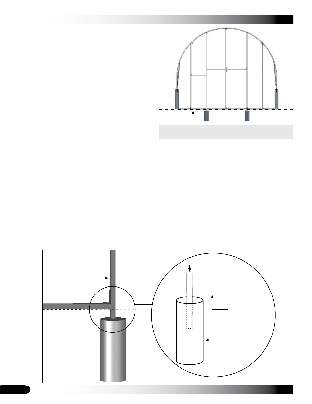
Determine the required width of the door (if equipped) and insert one 1.75" x 1.75" square tube (104075) into the 5.
concrete approximately 8". See diagram below. Repeat the step and verify that the tubes are plumb and the correct
distance apart. End frame diagrams shown in these instructions may show a door opening with different dimensions.
Section of the assembled
End Wall Frame.
*1.75" x 1.75" square
tube (104075): Half in
the concrete and half
exposed.
Ground Level
Concrete
*Not shown to scale.
6
Revision date: 09.13.10

Assemble the End Frame
After the ground posts are set, assemble the remainder of
the end frame.*
Angled Bracket (#QH1330)•
Carriage bolts and nuts and Tek screws (#FA4482B)•
Band clamps and 104074 brackets•
2" x 2" square tube (105328) and 104075 inserts•
1.5" x 1.5" square tube (end wall frame)•
*Refer to the Front Profile diagrams for door framing and
hardware. Diagrams are specific to a 8' x 8' overhead door.
Adjust the dimensions as needed to account for different
door sizes.
Complete the following steps:
Using the dimensions on the Front Profile diagrams (or 1.
for the doors if equipped) and the 2" x 2" square tubing
(105328), related hardware, and connectors, assemble
the door frame of the end wall. Cut tubes to length as
needed.
2" x 2" Tubes
Ground Level
2" x 2" Tubes
NOTE: The dashed lines above show where to install
the 2" x 2" square tubes. Consult the Front Profile
diagram to properly position and connect the brackets.
The lower end of each 2" x 2" main door frame vertical
slides over a 1.75" x 1.75" ground post set in concrete.
Secure the connection by installing Tek screws on the
back or inside surface of the verticals.
Splice the joints of the 2" x 2" tubes using a 104075
(1.75" x 1.75") square tube insert for each splice. Install
Tek screws to secure each splice.
Do not install Tek screws on surfaces where the end
panel (if equipped) or overhead door (if equipped) are
positioned. Consult the installation instructions that
shipped with the door for additional information.
Revision date: 09.13.10
CLEARSPAN™ END WALL FRAMING KITS
After 2" x 2" door framing is installed, repeat steps to 2.
assemble remaining end wall framing using 1.5" x 1.5"
square tubing (102897) and the related connectors.
NOTE: The dashed lines identify the remaining end
frame members to install. These are the 1.5" x 1.5"
square tubes. (Cut tubes to length as needed.)
Secure each tube splice using a Tek screw. Install
the screws in a position that will not interfere with the
installation of additional end frame components, the
end panel (if equipped), or door (if equipped).
Position center vertical between header and peak of
end rafter as needed to avoid conflicts with the clamps
and main frame components attached to the end rafter.
See the Front Profile diagrams for a similar comment.
The end panel (additional purchase required) for this
end wall includes a 12" vertical pocket centered in the
end panel. If installing this end panel, do not install the
center vertical end frame tubes until panel is installed.
The vertical frame tube is slid into a pocket of the end
panel after the panel is partially installed. This frame
tube is then secured to the end frame and end rafter as
shown. See the arrows in the above diagram.
If an overhead door (additional purchase required) is
to be installed, do not install the center vertical and the
base rail within the framed door opening.
After assembling end wall frame (or frames), inspect 3.
frame for sharp edges and bolts that could damage end
panel (if equipped) or main cover when it is pulled back
into place. Tape over or file the sharp edges as needed.
Install the end panel if equipped. 4. (Additional purchase
required for the end panels and doors.)
NOTE: If you are covering the end frame with
something other than an end panel, install that material
now and then secure the main cover of the shelter.
ATTENTION: If attaching end framing to a concrete
base (optional), skip to the Attach End Framing
to Concrete section before installing end panel (if
equipped).
7

CLEARSPAN™ END WALL FRAMING KITS
END PANEL INSTALLATION (if purchased)
The following procedure describes installing an end panel
(additional purchase required). Some steps may not apply
to your (or a custom) end panel.
SPECIAL NOTE: Depending on their locations and the
main shelter design, the ratchets used to secure the main
cover bonnet at the ends of the building may need removed
before the end panel is installed. These ratchets are
reinstalled once the end panel is attached.
If you are installing an overhead door, do not install a
base rail between the door jambs.
The end wall shown in the diagrams that follow may differ
in design and size. The steps to install the basic end panel
are the same despite these obvious differences.
With the lower edge of the end panel in position, 3.
secure the top end of the panel to the backside of the
end rafter using a few fabric clips and Tek screws.
NOTE: These fasteners are used to temporarily hold
the end panel in place while the lower edge is secured
to the base rail.
With the top edge temporarily secured to the end rafter, 4.
move to the bottom of the panel outside the frame.
Stretch and secure the lower panel edge to the base
rail using Tek screws and washers.
Upper
Tube
Required parts include:
End panel and fabric clips•
FA4482B Tek screws•
FAMF01B Washers•
DO NOT ATTEMPT
TO PULL THE END
PANEL INTO POSITION
ON WINDY OR STORMY
DAYS!
Complete these steps to install a typical end panel:
Spread the end panel out on the ground (pocket side 1.
up) and center the end panel as needed.
With the proper lift (or ladders) positioned inside the 2.
frame and with assistance, pull the end panel up and
over the top of the end rafter.
View of end panel
from inside the
frame
NOTE: Square the end panel on the end frame and
verify that the bottom edge is in line with the base rail.
This procedure describes attaching the panel bottom
to the base rail using Tek screws and washers
(FAMF01B) installed from the outside.
The end panel can also be pulled under and secured
to the inside surface of the base rail using the same
fasteners. That installation is not shown.
Lower
Tube
NOTE: Space the fasteners evenly along the base rail
at 16" to 24" intervals.
With the panel secured along the bottom, move to the 5.
upper edge and install the center end frame verticals
in the pocket of the end panel and attach the frame
members to the end wall frame. See the diagram to the
left and in the Quick Start section for locations.
In the diagram (left), the shaded area represents the
center pocket of the end panel. Vertical dashed line
indicates the location of the end frame members as
installed inside the end panel pocket.
NOTE: Trim the pocket material as needed to install
the verticals and attach the frame members to the
end rafter, header, and base rail. DO NOT INSTALL
THE LOWER TUBE IF YOU ARE INSTALLING AN
OVERHEAD DOOR IN THE END WALL.
Loosen the temporary clips (installed in Step 3 above) 6.
and stretch the end panel up and over the end rafter.
Attach the fabric clips to secure the end panel to the 7.
rafter. Evenly space the fabric clips at 24" intervals.
Keep the panel evenly stretched as you go.
NOTE: Use Tek screws and washers to secure the end
panel to the pony wall.
Install doors if equipped (additional purchase required) 8.
or reattach the bonnet ratchets and main cover.
8
Revision date: 09.13.10

CLEARSPAN™ END WALL FRAMING KITS
Cut Door Openings (additional door purchase required)
ATTENTION: For best results and to keep the stretched panel in position, install Tek screws and washers from the outside
around the door frame to secure the end panel to the door jambs and header. (See dashed lines Fig. 1.) Do this before
cutting the opening in the panel. If you do not want to install screws through the panel, continue with Step 1.
These steps describe one way to cut a door opening:
Working from inside the frame, mark a 12" border along 1.
the door jambs and below the header. (Consult the
diagram below.) These 12" flaps are wrapped around
the door framing and secured to the inside of the door
frame once the final diagonal cuts are made.
NOTE: If a base rail is installed between the door
jambs, remove the base rail and continue.
Using the diagram as a guide, cut the end panel to 2.
remove the section that is shaded.
(Can be used for most door installations.)
Cut #1
This portion of the
end panel is wrapped
around and secured
to the door frame.
Figure 1
Example Door Opening
Header
12"
PANEL
When installing a
door, do not install
a base rail in this
location.
Cut #2
Door Jamb
Base
Rail
Make two (2) diagonal cuts in the end panel as shown above (Cut #1 and Cut #2) to create the 12" flaps.3.
Continue with the Secure End Panel to Door Frame instructions that follow.4.
Revision date: 09.13.10
PANEL
12"
Door Jamb
Remove the shaded portion
of the end panel material.
Remove this shaded
portion of the panel.
Ground
Level
View above shows the end panel as seen from inside the frame.
PANEL
12"
Base
Rail
9

CLEARSPAN™ END WALL FRAMING KITS
Secure the End Panel to the End Frame
The frame shown in the following diagrams may differ from the actual frame. Installation steps are the same.
With door openings cut, secure the end panel to the door frame using Tek screws and washers. See diagram below. 1.
NOTE: For the exposed corners of the door frame that remain, cut out a 16" x 16" piece of material from the scrap
end panel material and secure the piece to the exposed corners using Tek screws and washers (if desired).
Secure the end
panel to the inside
surface of the
frame tube using
a Tek screw and
washer.
View shows the
inside surface of
the installed end
panel.
End Panel
Install Tek
screw here
Door Jamb
Inside View
ATTENTION: DO NOT secure the end panel to the inside or backside of the door frame tubes. Some doors kits use
this surface for tracks and brackets. Check the instructions that shipped with the door for additional details.
Repeat the steps to install the end wall and end panel for the remaining end of the building if equipped.2.
Base Rail
Install the door or doors according to the instructions included with those components.3.
After doors are installed according to the door manufacturer's instructions, reattach the bonnet ratchets and cover. 4.
NOTE: The arrows in the above diagram shows where to reattach the end ratchets to secure the bonnet of the main
cover. The ratchets are typically reattached through the end panel and to the end wall base rail. Pull the main cover
bonnet back over the end rafter and use the bonnet straps as a guide to properly position each ratchet.
ATTENTION: If attaching ratchets to a concrete base (optional), skip to the Attach Ratchets to Concrete section on
the following page.
10
Read the care and maintenance information that follows.5.
Revision date: 09.13.10

CLEARSPAN™ END WALL FRAMING KITS
ATTACH END FRAME TO CONCRETE (optional) ATTACH RATCHETS TO CONCRETE (optional)
Additional materials required to secure the end frame base
rail or rails to the concrete base are not included and must
be purchased by customer. Materials and frame shown in
the following diagrams may differ from actual purchases.
Use the following information to determine the size of the
anchor bolt that best applies to your purchase.
Length of Anchor Bolt equals (=):
Thickness of material to be fastened
+plus minimum embedment (see manufacturer recommendation)
+plus 1" for nut and washer application.
Verify base rail is in the correct position. Determine 1.
where to install the first customer-supplied wedge
anchor bolt. Drill a hole through both the base rail and
concrete base according to the anchor bolt size.
Sample
wedge
anchor bolt
Additional materials required to secure ratchets to a
concrete base are not included and must be purchased
by customer. Materials and frame shown in the following
diagrams may differ from actual purchases.
Consult the boxed information to the left to determine the
size of the anchor bolt that best applies to your purchase.
Determine where the first ratchet will be attached and 1.
drill the mounting hole according to the anchor bolt
size.
IMPORTANT: DO NOT over-drill hole. Wedge anchor
bolt will not work properly if hole is too deep.
Insert anchor bolt into drilled hole. Firmly tap with a 2.
hammer to secure wedge anchor into concrete.
NOTE: Depending on wedge anchor bolt, verify that the
washer and securing nut are attached before driving
the anchor bolt into concrete. Striking bolt may cause
thread damage and prevent the nut installation.
Tighten the nut.3.
NOTE: Hole needs to be deep enough that the anchor
bolt will not interfere with ratchet operation.
With ratchet in the open position, insert anchor bolt 2.
through ratchet hole and into mounting hole. Firmly tap
with a hammer to secure wedge anchor into concrete.
Repeat for each anchor bolt until base rail or rails are 4.
adequately secured to the concrete base.
NOTE: Evenly space each anchor bolt approximately
every 4' or so.
Revision date: 09.13.10
NOTE: Depending on wedge anchor bolt, verify that the
washer and securing nut are attached before driving
the anchor bolt into concrete. Striking bolt may cause
thread damage and prevent the nut installation.
Tighten the nut.3.
Test ratchet operation. Cut excess if needed.4.
Repeat for each ratchet.5.
11

CLEARSPAN™ END WALL FRAMING KITS
SHELTER CARE AND MAINTENANCE
Proper care and maintenance of your ClearSpan™ building
is important. Check the following items periodically to
properly maintain your building:
Regularly check the main cover and panels (if •
equipped) to see that these remain tight and in proper
repair.
Check the cable turnbuckles and cable clamps to •
see that these remain tight (if equipped). Tighten as
needed.
Check the cable (if equipped) to verify that it is not worn •
or wearing on a frame member.
Frequently check the anchoring system and all •
components. Replace worn or damaged parts
immediately.
Check all fasteners frequently to verify that these •
remain tight and in good repair.
Do not climb or stand on the building or frame at •
anytime.
Remove debris and objects that may accumulate on •
the shelter. Use tools that will not damage the cover
when removing debris.
Space below is reserved for customer notes.
Remove snow to prevent excess accumulation. Use •
tools that will not damage the cover when removing
snow. Never allow snow to accumulate on the main
cover or to remain against the sides or end panels after
it is removed from the main cover.
Check the contents of the shelter to verify that •
nothing is touching the cover or panels (if equipped)
that could cause damage.
Replace all worn or damaged parts.•
For replacement or missing parts, call 1-800-245-9881 •
for assistance.
NOTE: With the exception of Truss Arch buildings,
ClearSpan™ shelters and greenhouses do not have any
tested loading criteria.
12
Revision date: 09.13.10

QUICK START GUIDE
20' Wide x 16' High End Frame Kit
The end frame kit does not include the rafter, struts,
concrete, or overhead door as shown in the diagram.
CLEARSPAN™ END WALL FRAMING KITS
Customer-supplied
Concrete
End frame shown may differ from the actual end frame. Rough door dimensions depend on the door that will be
installed if equipped. Consult the information that ships with the door to accurately set the rough door framing.
Revision date: 09.13.10
Ground Level
13

CLEARSPAN™ END WALL FRAMING KITS
3'-1 3/4" 4'-1"4'-1" 3'-1 3/4"
2"
*See Note
105328
105328
105328
105328
102897
102897
102897
Shelter
102897
102897
105328
102897
102897
Center of
102897
8'-0"
6'-9 1/2"
102897
102897
FRONT PROFILE (A)
Frame shows dimensions
for an 8' x 8' overhead door.
Actual dimensions may
differ for your end frame if
equipped with a door.
Additional purchase required
for door and attachment
hardware.
Ground Level
The above diagram shows where to install the 2.0" x 2.0" square (105328) tubing and the
1.50" x 1.50" square tubing (102897). These frame tubes are sent in full lengths. Cut the upper
sections to the required length when constructing the end framing. Allow room to install the
band clamps and the square-to-round tube brackets (104074) at the top of each vertical frame
tube.
ATTENTION: SECURE EACH 2" X 2" DOOR FRAME TUBE USING TEK SCREWS AND
THE 1.75" X 1.75" (104075) SQUARE TUBE INSERTS. BE SURE TO INSTALL THE TEK
SCREWS IN A LOCATION THAT WILL NOT INTERFERE WITH THE INSTALLATION OF THE
END PANEL OR OTHER COMPONENTS IF EQUIPPED. CHECK THE DOOR INSTALLATION
INSTRUCTIONS THAT SHIPPED WITH THE DOOR FOR ADDITIONAL DETAILS.
14
The length of this
1.5" x 1.5" tube (both
ends of the base rail)
depends on the width
of the shelter.
Cut to the required
length and secure
using QH1330
brackets and Tek
screws.
If Tek screws do
not work for your
application, purchase
the required fasteners
locally.
Revision date: 09.13.10

Secure the band
clamp to the rafter
as shown.
CLEARSPAN™ END WALL FRAMING KITS
FRONT PROFILE (B)
This location of the main frame purlin connection may not
apply to your building. Install end framing as needed to avoid
conflicts with the components of the main frame.
2" x 2"
104075
2" x 2"
Tek Screws
Position
this header
tube as
needed if
installing a
pedestrian
door.
Tek Screw
QH1330
Splice the
2" x 2"
tubes using
a 104075
insert and
Tek screws.
ATTENTION: The spacing shown above may differ from the spacing of the actual end wall. The spacing of the individual
end frame members and the size of the door opening depends on the door (if equipped). If doors are to be installed, frame
the end wall as needed to accommodate the door or doors. (Additional parts may be required for door installation.)
The verticals installed above and below the door header are installed slightly off-centered to avoid conflicts with the
hardware attached to the end rafter for the main frame of the shelter. Position these as needed to avoid frame component
conflicts.
Revision date: 09.13.10
15

CLEARSPAN™ END WALL FRAMING KITS
DOOR FRAME DIAGRAM: SPECIAL NOTES
Doors are not included with the end frame kit. Additional purchase is required.
ATTENTION: For some doors, the upper brackets are mounted wider than the actual door frame. In those instances, cut a
16" section of stock door frame tubing and mount it to the outside of each vertical door frame using the supplied carriage
bolts and nuts in the locations shown in the diagram below.
Header
END WALL SPECIAL NOTE: If no door is to be
installed in the end wall, attach square tubing using the
#QH1330 brackets in the areas identified by the dashed
lines below.
The end wall base rail provides a place to secure
the ratchets for the end panel horizontal conduit (if
equipped). In addition, the end ratchets used to secure
the main cover bonnet are attached to the base rail.
Use the main cover bonnet straps as guides to properly
position and attach these ratchets.
This tube is
cut from the
remainder
of end wall
framing.
16
Install square tube at the bottom of the door
opening and in the center of the opening
when no door is installed.
Remove these frame tubes to install a door.
Revision date: 09.13.10

Space below is reserved for customer notes.
CLEARSPAN™ END WALL FRAMING KITS
Revision date: 09.13.10
17
 Loading...