

ClearSpan 104137, 104138, 104141, 104139, 104140 User Manual
...
CLEARSPAN™ HIGH TUNNELS AND CANOPIES
ClearSpan™ High Tunnel
Add-A-Bay System
©2009 ClearSpan™
All Rights Reserved. Reproduction
is prohibited without permission.
Revision date: 01.28.09
Photo may show a different but similar model.
STK# DIMENSIONS
104137 52' W x 12' H x 24' L
104138 52' W x 12' H x 48' L
104139 52' W x 12' H x 72' L
104140 52' W x 12' H x 96' L
104141 78' W x 12' H x 24' L
104142 78' W x 12' H x 48' L
104143 78' W x 12' H x 72' L
104144 78' W x 12' H x 96' L
1

CLEARSPAN™ HIGH TUNNELS AND CANOPIES
YOU MUST READ THIS DOCUMENT BEFORE YOU
BEGIN TO ASSEMBLE THE SHELTER.
LOCATION
Choosing the proper location is an important step before
you begin to assemble the structure.
The following suggestions and precautions will help you
determine whether your selected location is the best
location.
• Never erect the structure under power lines.
Thank you for purchasing this ClearSpan™ shelter. When
properly assembled and maintained, this product will
provide years of reliable service. These instructions include
helpful hints and important information needed to safely
assemble and properly maintain the shelter. Please read
these instructions before you begin.
If you have any questions during the assembly, contact
Customer Service for assistance.
SAFETY PRECAUTIONS
• Wear eye protection.
• Wear head protection.
• Wear gloves when handling metal parts.
• Use a portable GFCI (Ground Fault Circuit Interrupter)
when working with power tools and cords.
• Do not climb on the frame during or after construction.
• Do not occupy the structure during high winds,
tornadoes, or hurricanes.
• Provide adequate ventilation if the structure is
enclosed.
• Do not store hazardous materials in the structure.
• Provide proper ingress and egress to prevent
entrapment.
• Identify whether underground cables and pipes are
present before preparing the site or anchoring the
structure.
• Location should be away from structures that could
cause snow to drift on or around the building.
• Do not position the structure where large loads such as
snow and ice, large tree branches, or other overhead
obstacles could fall.
SITE
After choosing a location, proper preparation of the site is
essential. Follow the information below.
• A level site is required. The site must be level to
properly and safely erect and anchor the structure.
• Drainage: Water draining off the structure and from
areas surrounding the site should drain away from the
site to prevent damage to the site, the structure, and
contents of the structure.
WARNING: The individuals assembling this structure
are responsible for designing and furnishing all
temporary bracing, shoring and support needed during
the assembly process. For safety reasons, those who
are not familiar with recognized construction methods
and techniques must seek the help of a qualified
contractor.
2
Revision date: 01.28.09

ASSEMBLY PROCEDURE
Following the instructions as presented will help ensure the
proper assembly of your structure. Failing to follow these
steps may result in an improperly assembled and anchored
structure and will void all warranty and protection the owner
is entitled to.
The steps outlining the assembly process are as follows:
1. Verify that all parts are included in the shipment. Notify
Customer Service for questions or concerns.
2. Read these instructions, and all additional
documentation included with the shipment before you
begin assembling the structure.
3. Gather the tools, bracing, ladders (or lifts), and
assistance needed to assemble the structure.
4. Check the weather before you install the roof cover
and any panels (if equipped). Do not install covers or
panels on a windy or stormy day.
5. Re-evaluate the location and site based on the
information and precautions presented in the
documentation included with the shipment.
6. Prepare the site (if applicable).
7. Assemble the frame components in the order they are
presented in these instructions.
8. Properly connect the assembled frame to the ground
posts.
9. Install, tighten, and secure the end panel and main
cover (if equipped). This applies to covers that stretch
over the frame assembly. Your shelter may include roof
panels or side panels or both.
10. Read the care and maintenance information at the end
of these instructions.
CLEARSPAN™ HIGH TUNNELS AND CANOPIES
• Conduit: An assembly of pipes used to secure the
main cover and end panels (if equipped). Purlins and
some strut assemblies also consist of connected pipes
to form a conduit. Each pipe joint of a conduit assembly
is secured with a self-tapping Tek screw.
• Coupler or Fitting: A part of the frame assembly
where legs, purlins and rafter pipes are inserted and
secured. In most instances, 3-way and 4-way couplers
are used. In some larger applications, couplers are
used to secure the joints of the different rafter sections
during the assembly of the rafters. Some shelters do
not use couplers.
• Foot or Rafter Foot: The part attached to and found
at the base of the rafter or leg of the shelter. Depending
on the shelter, the foot is an optional purchase. Some
shelters do not offer an optional foot. Some use 1-way
connectors or ground posts.
• Must Read Document: This document includes
building and shelter anchoring instructions, steps for
end wall reinforcement, safety precautions, and notices
and warnings. The Must Read document is sent with
all shelters and buildings. If you did not receive a Must
Read document, contact Customer Service to request
one.
• On-Center: Term used to describe a measurement
taken from the vertical center of the rafter or frame
member to the vertical center of another.
• Purlin: The pipe assembly that runs perpendicular to
the rafters or framework that supports the main cover.
Purlins are found on the sides and roof areas of the
assembled frame, are evenly spaced, and typically run
from the front to the back of the shelter.
• Plain or Straight Pipe: A term used to describe a pipe
that has the same diameter or width throughout its
entire length.
11. Complete and return all warranty information as
instructed.
LIST OF WORDS AND PHRASES
Before you begin, it is important to become familiar with the
words and phrases used in this instruction manual.
These words and phrases are common to most
ClearSpan™ shelters and identify the different parts of
the shelter. (Some are used in this document. Others may
not apply to this particular shelter.) These terms describe
the shipped parts and can also be found on the materials
list/spec sheets included with the shipment. To aid in the
assembly, read through the following definitions before you
begin to assemble your shelter.
Revision date: 01.28.09
• Strut: A strut is usually a length of pipe with two
flattened ends and is used for diagonal bracing of the
shelter frame. A strut is typically secured to the frame
work by special brackets and bolts.
• Swaged End or Swaged Pipe: The term “swaged''
refers to the tapered end of the pipe or tube. Swaged
ends of a pipe can be inserted into couplers and the
straight ends of other pipes.
• Tek Screw: A self-tapping fastener used to secure pipe
joints and to fasten brackets to rafters.
3

CLEARSPAN™ HIGH TUNNELS AND CANOPIES
REQUIRED TOOLS
The following list identifies the main tools needed to
assemble the shelter. Additional tools and supports may be
needed depending on the structure, location, and
application.
• Tape measure or measuring device
• Variable speed drill and impact driver (cordless with
extra batteries works best)
• Wrenches or ratchet and socket set (recommended)
• Ropes long enough to reach over the frame (if optional
cover was purchased)
• Hammers and gloves
• Metal file
• Duct tape (supplied by customer)
• Box cutter or utility knife
• Ladders, work platforms, and other machinery for lifting
designed to work safely at the height of the frame
UNPACK AND IDENTIFY PARTS
Space below is reserved for customer notes.
The following steps will ensure that you have all the
necessary parts before you begin to assemble the shelter
frame.
1. Unpack the contents of the shipment and place where
you can easily inventory the parts. Refer to the Bill of
Materials/Spec Sheets.
2. Verify that all parts listed on the Bill of Materials/Spec
Sheets are present. If anything is missing or you have
questions, consult the Pictorial Parts Guide, Quick Start
section and all diagrams for clarification, or contact
Customer Service.
NOTE: At this time, you do not need to open the plastic
bags containing smaller parts such as fasteners or
washers (if equipped).
4
Revision date: 01.28.09
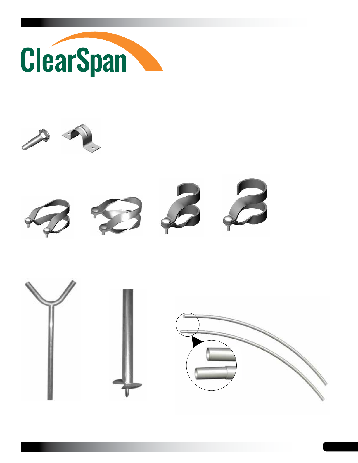
The following graphics and photos will help you identify the
different parts. (Some parts are not shown.)
CLEARSPAN™ HIGH TUNNELS AND CANOPIES
FA4482B
Tek Screw
102547
Cross Connector
QH1070
Pipe Strap
102548
Cross Connector
102856
End Clamp
102857
End Clamp
103296
V-Connector
Revision date: 01.28.09
103297
Ground Post
With Auger
Plain
Swaged
Swaged and Plain Rafter Sections
5

CLEARSPAN™ HIGH TUNNELS AND CANOPIES
OVERVIEW
This section describes assembling your shelter. For details,
please see section; Assembling the Shelter Components.
See illustration below to identify main parts of the shelter.
1. Locate the required parts for each assembly procedure.
2. Assemble the rafters and frame.
3. Anchor the frame.
ClearSpan™ High Tunnel
Add-A-Bay System
4. Attach cover (additional purchase required).
Interior Rafter
End Rafter
Upper Strut
Purlins
Lower Strut
Ground Level
6
Auger Ground Post
Frame shown may vary in length from actual frame.
Revision date: 01.28.09
LAY OUT THE BUILDING SITE
After the site is prepared, lay out the building site.
Taking these steps before assembling the shelter saves
time and ensures that the structure is positioned as
desired.
CLEARSPAN™ HIGH TUNNELS AND CANOPIES
3. After the first corner post is in place, string a line the
width of the first bay section (26' center-to-center) and
drill the second corner post into the ground just enough
to hold it in place.
4. Use a transit or line level to drill the second corner post
to the same depth as the first corner post.
Ground posts must be driven to the proper depth. Width of
the shelter is measured from the center of one ground post
to the center of the remaining ground post.
SQUARE THE SITE
Gather the parts:
• Auger ground posts (#103297)
• V-connectors (#103296)
• 5/16" x 2-1/2" machine bolts and 5/16" nuts
• End Clamp (#102857)
• Customer-supplied post hole digger (if needed)
1. Attach a V-connector to each auger ground post using
a 5/16" x 2-1/2" machine bolt and 5/16" nut.
V-connector
Use the lower hole in
the V-connector and the
upper hole in the auger
ground post to connect
with the nut and bolt.
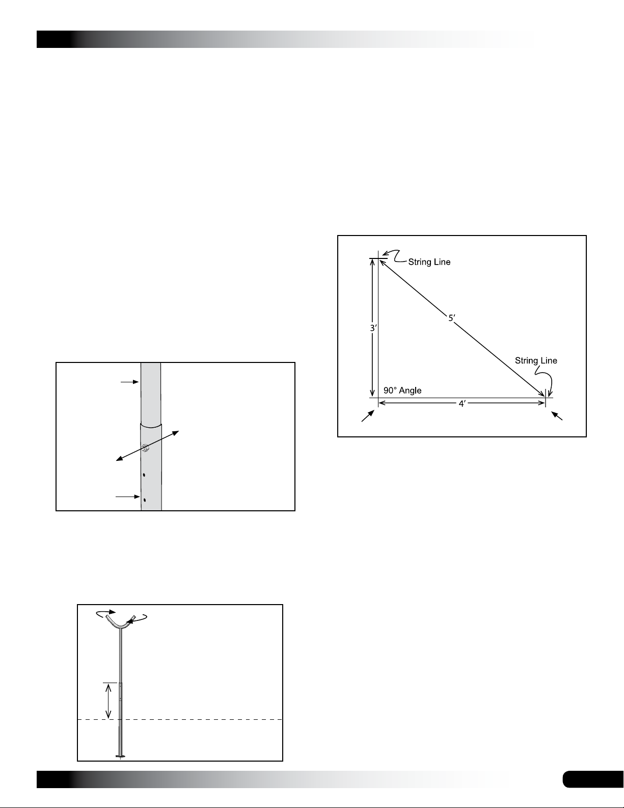
5. String a line at least as long as the building from the
first ground post at 90°.
NOTE: A transit can be used to ensure an accurate 90°
angle, or the 3-4-5 rule can be used. Refer to diagram.
Using multiples of 3-4-5 such as 6-8-10 or 12-16-20
helps to maintain an accurate 90° angle.
shelter length
1st corner 2nd corner
6. After squaring the position of the building, measure the
length and drill the next corner post.
Auger
Ground Post
2. Identify a corner where a ground post will be positioned
and drill the first corner auger ground post into the
ground using the "V" as handles. Use a post hole
digger if needed.
NOTE: The top of the auger ground post will be one (1)
foot above the finished grade when properly driven.
Position the post with the
"V" handles parallel to
the front and back of the
shelter. The "V" section of
the posts will aligned with
1'
the rafters.
Ground Level
7. Repeat the same step for the last corner post.
NOTE: The distance measured diagonally between
corner ground posts must be equal for the building to
be square.
8. Check all dimensions (and adjust if needed) before
drilling the remaining posts to the required height.
9. After all four corner posts are accurately installed, tie a
string line between the tops of the corner ground posts
on the same side of the shelter. The string is used to
identify the tops of all side ground posts. The string
must remain tight and level.
10. Use a tape measure to mark the 72" on-center
locations of the remaining ground posts.
11. Drill the side ground posts into the ground at the
required 72" on-center width and the height identified
by the string.
NOTE: Verify that the holes in the ground posts are in
the proper position and that each post is plumb and at
the correct depth.
Revision date: 01.28.09
7
CLEARSPAN™ HIGH TUNNELS AND CANOPIES
LAY OUT THE BUILDING SITE (CONTINUED)
12. Using the remaining assembled posts, install the
ground posts of the 2nd bay in the same manner as the
previously described. Verify on-center dimensions.
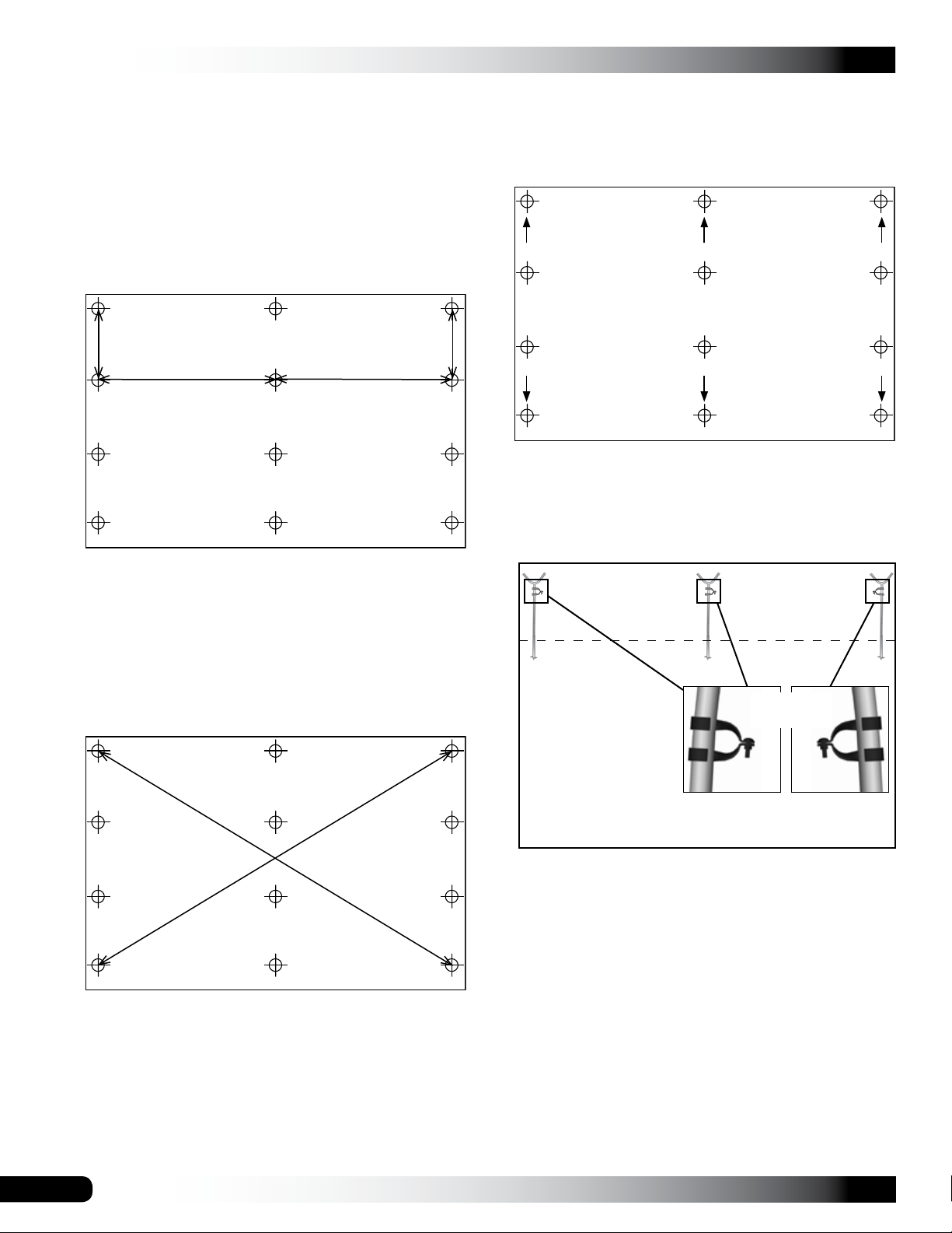
NOTE: The diagrams that follow illustrate an example
of a 2-bay shelter. If you have purchased a 3-bay
shelter, add another row using the same dimensions
shown.
Back End
14. After the ground posts have been set in the correct
position, detach each V-connector along the front and
back ends of the shelter from the ground posts.
Back End
6' on-center
26' on-center 26' on-center
6' on-center
Front End
NOTE: Ground post layout shown above may differ
from your shelter. Diagram used for illustration
purposes only.
13. Verify that the on-center width of the frame is uniform
between the corner ground posts and that the frame is
square.
Front End
15. Slide a 102857 end clamp on each of these posts as
shown below, and reattach the V-connectors to the
ground posts.
Ground Level
Verify that the end
clamps are to the
#102857
End Clamp
inside of the shelter
on each side. The
end clamps on the
middle posts can be
on either side.
NOTE: The frame is square when the two diagonal
measurements are the same.
8
View of the posts and clamps as shown from the
outside when the frame is assembled.
NOTE: Use a piece of duct tape (if desired) to keep the
clamps from sliding.
16. Continue with the Rafter Assembly that follow.
Revision date: 01.28.09
ASSEMBLING THE SHELTER COMPONENTS
NOTE: Assistance is required to assemble the frame.
RAFTER ASSEMBLY
Gather the parts:
• Round rafter (#26R1601)
CLEARSPAN™ HIGH TUNNELS AND CANOPIES
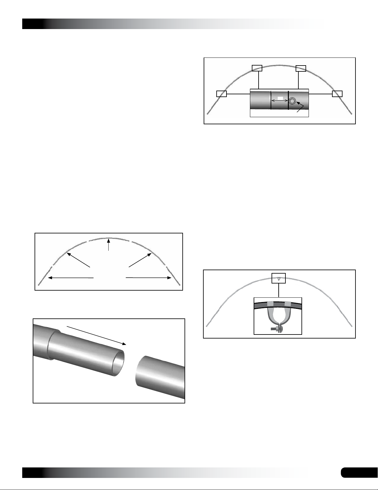
3. With the main rafter pipes seated at each joint and the
rafter positioned on a flat surface, secure the joints with
self-tapping Tek screws.
• Round rafter (#26R1602)
• Round rafter (#166S051)
• End clamp (#102856)
• Tek screws (#FA4482B)
• Nut setter (3/8" x 2-9/16" magnetic)
Rafter Assembly Procedure
Each rafter assembly consists of five (5) rafter pipes: two
(2) swaged pipe sections (#166S051) , two (2) swaged
pipe sections (#26R1601) and one (1) plain pipe section
(#26R1602).
1. Select the five (5) pipes needed to assemble a rafter
and arrange these on a flat surface as shown below for
assembly.
(#26R1602)
(#26R1601)
1˝
Tek screw
ATTENTION: Install the screws so they will not touch
the cover once it is installed (if equipped). This is
typically on the backside of the rafter, which will be the
surface visible from the inside of the shelter once the
frame is assembled.
4. Assemble all the rafters as described and continue with
the steps to complete the end rafters.
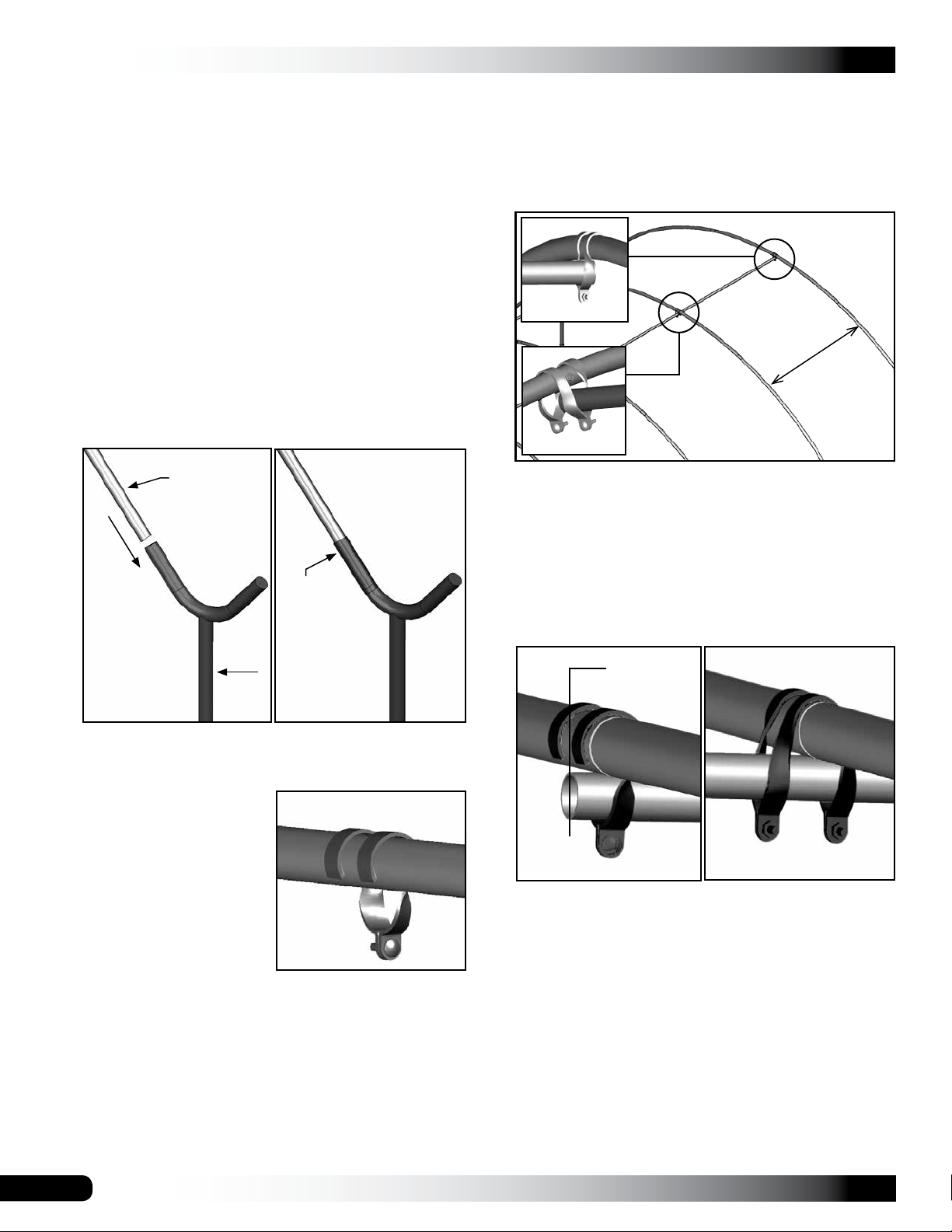
END RAFTER ASSEMBLY
Complete the following steps for the end rafters only. 2-bay
shelters have four (4) end rafters; 3-bay shelters have six
(6) end rafters.
1. Take one of the assembled rafters and place it on a flat
surface.
2. Slide one (1) end clamp onto the rafter in the location
noted below.
(#166S051)
2. Slide the swaged portion of each rafter pipe into the
plain end of the pipe as shown.
View of the clamp as shown from the outside when the
frame is assembled.
NOTE: Do not secure the clamp to the rafter at this
time. These clamps will be repositioned during frame
assembly when the purlin is added.
Use a piece of duct tape (if desired) to keep the clamps
from sliding when the rafter is lifted into position.
3. Repeat the same procedure for the other end rafters.
4. Continue with the Frame Assembly instructions.
Revision date: 01.28.09
9
CLEARSPAN™ HIGH TUNNELS AND CANOPIES
FRAME ASSEMBLY
Gather the parts:
• All rafter assemblies
• Pipe 1.315'' x 75'' swaged (#131S075)
• Pipe 1.315'' x 73.5'' plain (#131P0735)
• End clamps (#102856)
• Cross connectors (#102547 & #102548)
4. Position one (1) cross connector (102548) at the top of
the interior rafter assembly as shown below.
5. Take one (1) swaged 75" purlin section and insert each
through an upper clamp on the end rafter and through
the cross connectors near the top of the interior (or
second) rafter as shown below.
• Pipe straps (#QH1070)
• Lifts, ladders, and assistants
Frame Assembly Procedure
1. Using the proper lifts and with assistance, carefully
stand the first end rafter assembly and place the rafter
into the first set of ground posts.
Rafter
Post
Tek screw
Inside of
Shelter
Outside of
Shelter
#102856
6'
center-to-center
#102548
6. Verify that both rafters are plumb and properly spaced
(6' on center).
7. Tighten the upper cross connector on the interior rafter
and tighten the end clamp near the top of the end rafter
to secure the first purlin pipe.
NOTE: Do not allow the purlin to extend beyond the
end of the end rafter. See diagram below.
Do not allow the
purlin to extend
beyond the end
rafter.
NOTE: Verity that the end clamp is positioned as
shown below.
View of the end rafter and
clamp as shown from the
outside when the frame is
assembled.
Outside
Shelter
2. Verify the rafter is plumb and attach to the ground posts
using Tek screws.
ATTENTION: Install the screws so they will not touch
the cover once it is installed (if equipped).
3. Place an interior rafter assembly into a second set of
posts. Secure the leg pipes to the posts as previously
described.
10
End rafter view
Interior rafter view
Revision date: 01.28.09
 Loading...