

ClearSpan 103702, 103700, 103701 Instruction Manual
Poly Shelters
Note: Photo may be of a different but similar model
(Shown with Optional Expanded Metal Top)
© 2004 ClearSpan
All rights reserved. Reproduction prohibited without written permission.
Rev: 18 Mar 04
TM
Instruction Manual
Greenhouse Bench
SKU #103700 2' Wide x 8' Long
SKU #103701 4' Wide x 8' Long
SKU #103702 6' Wide x 8' Long
Introduction
Thank you for purchasing the ClearSpanTM Greenhouse Bench. We appreciate your patronage. We
hope you enjoy building and utilizing your bench. Please read this entire instruction manual before
starting to assemble your bench. If you require assistance during the construction process you may
call us at 1-888-603-4445.
A Word About Safety
Just as we want you to be pleased with your assembled bench, we donʼt want you to get hurt in the
process of building it! Our suggestions include the following:
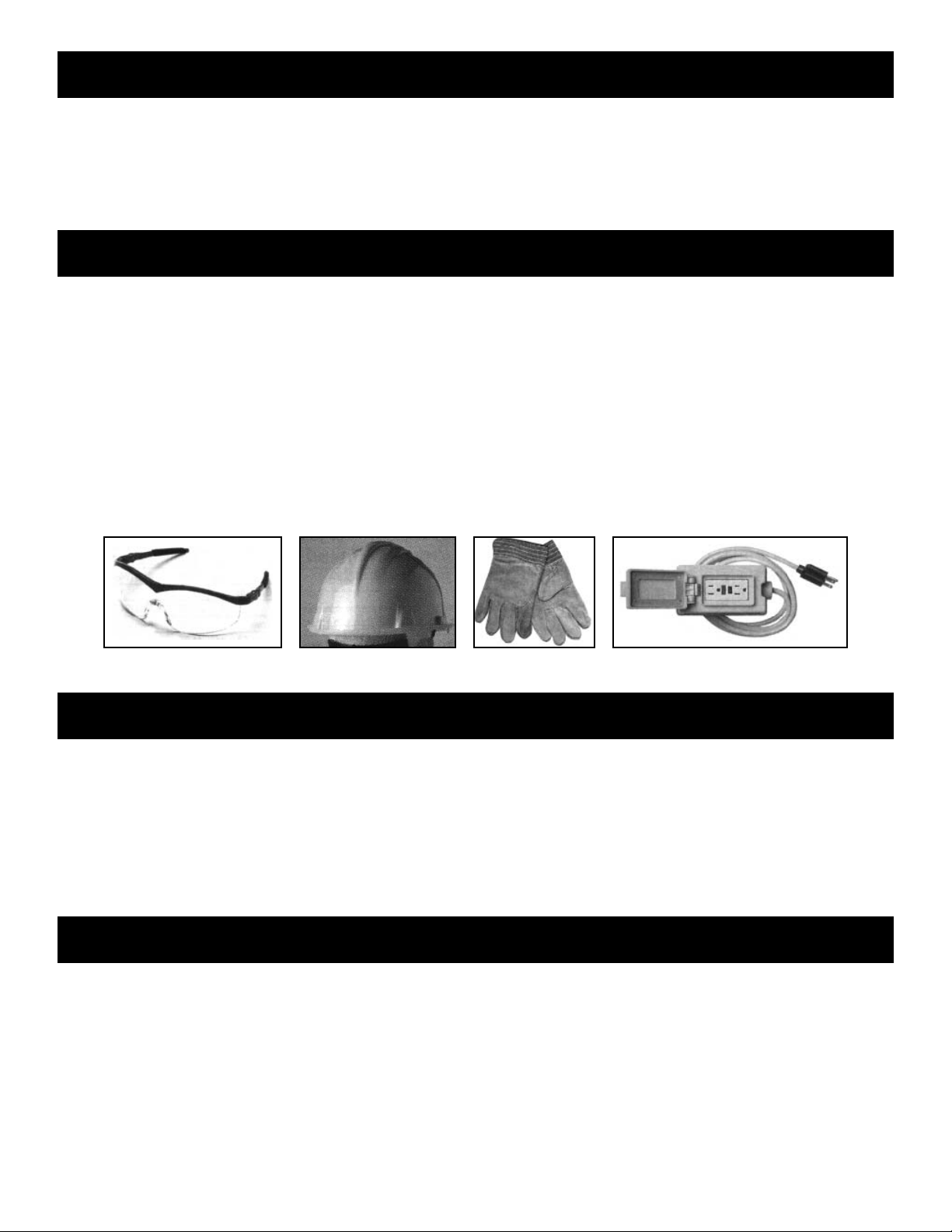
• Wear eye protection when drilling and power-screwing.
• Wear head protection when working with/under heavy parts including metal tubing.
• Wear gloves when handling metal parts due to sharp or rough edges.
• Use a portable GFCI when working with corded power tools.
• Do not climb on the bench or its frame. It is not designed to support human weight.
• If bench is moved after construction, inspect bench thoroughly before reuse.
• Use common sense at all times.
Required Tools
Before you start to build your bench you should assemble the following tools:
• Tape Measure at least as long as your bench
• Fine Point Marker to mark locations during assembly
• Electric Drill/Driver (cordless preferred)
• 5/16" Hex Driver Bit
Unpack & Identify Parts
Before you begin to assemble your bench you should first unpack the contents of your
shipment. During this process you will both verify that you have all the parts required to build your
bench and learn what all of the various parts look like.
Page 2
Parts List - Approximate (see list packed with your kit)
(2) Long extruded aluminum side rails with mitered ends (8' long)
(2) Short extruded aluminum end rails with mitered ends (2', 4', or 6' long depending on model)
(4) Steel legs with attached feet
(4) Galvanized steel tubing cross supports
(4) Galvanized steel split “T” clamps (2 halves with nut and bolt)
(4) Corner splice pieces
(16) Galvanized steel band clamps (with nut and bolt)
(4) Straight aluminum end braces
(4) Twisted aluminum side braces
(1) Package of Tek screws (self-drilling and self tapping)
(1) Expanded metal top (optional)
Bench Assembly
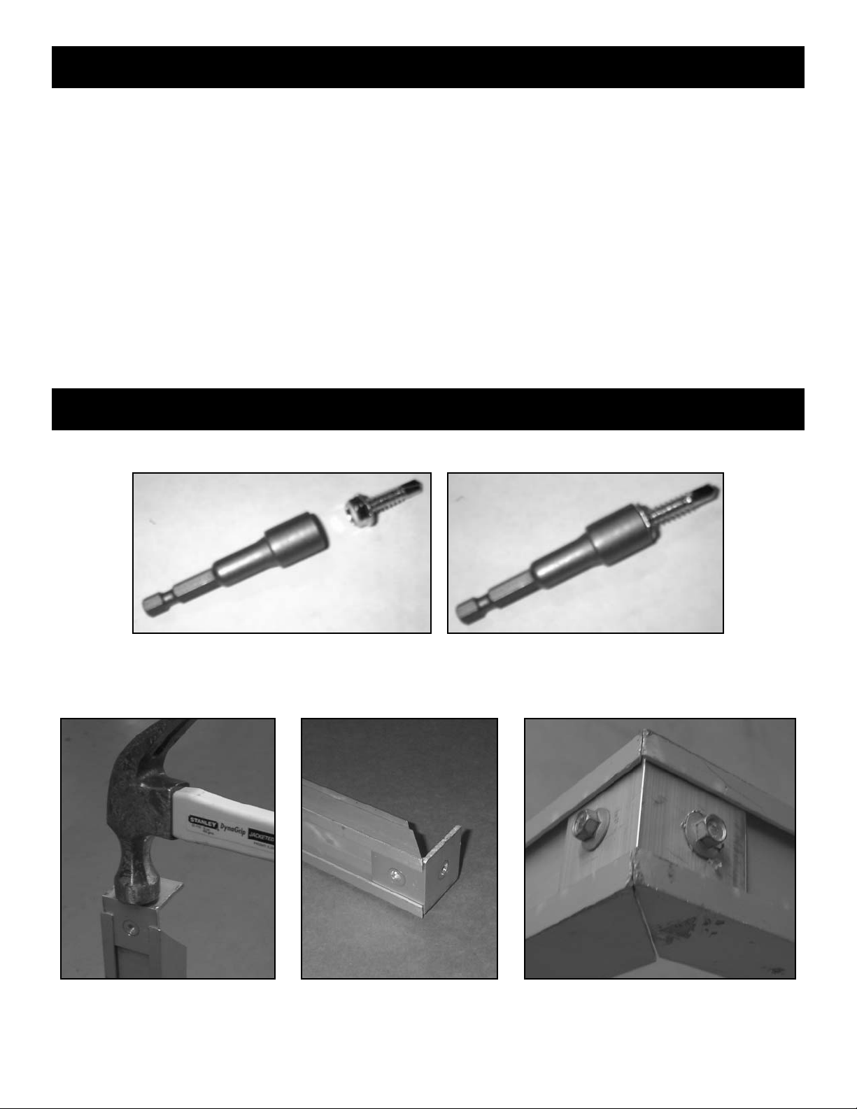
Step 1: Install a 5/16" hex driver bit into the chuck of your drill/driver.
Step 2: Attach (2) short side rails to (1) long end rail to form a U-shaped assembly. Use (1) corner
splice and (2) Tek screws in each corner. Be sure to line up the channels grooves before
inserting the Tek screws. Use a mallet if necessary to tap the splices into the channel grooves.
Page 3
 Loading...