

ClearSpan 103596 User Manual
CLEARSPAN™ END WALL FRAMING KITS
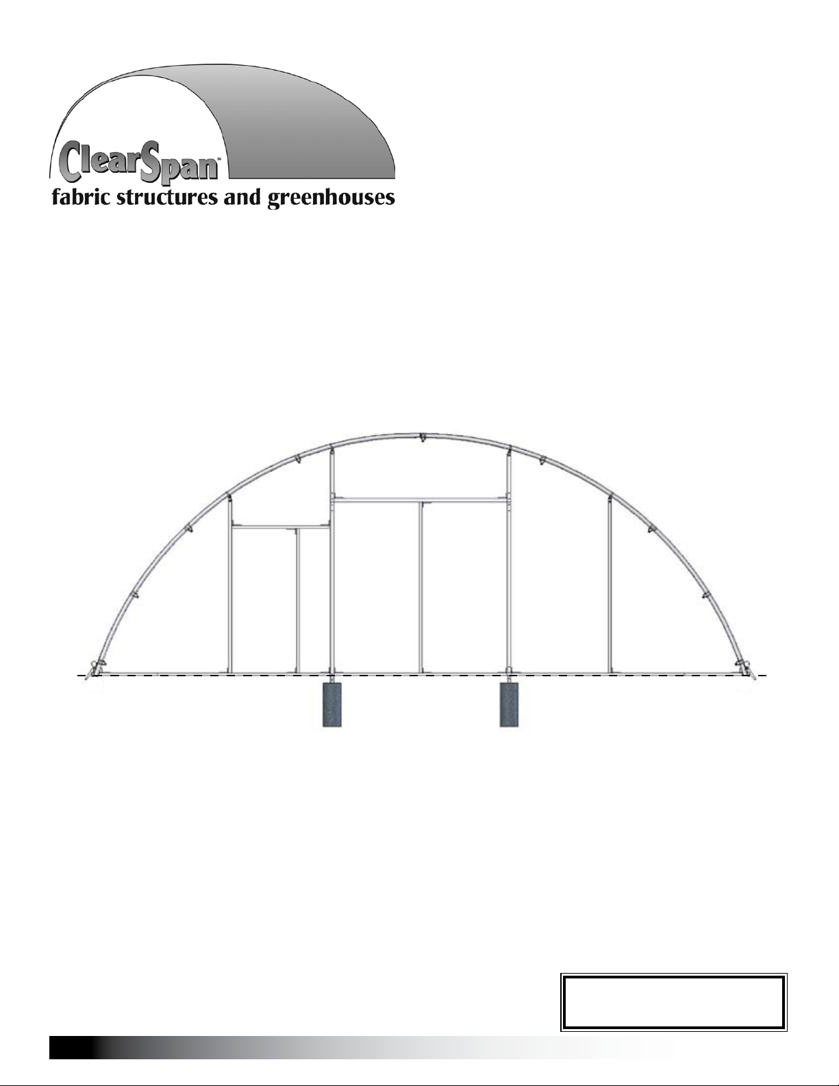
ClearSpan™ End Frame Kit
30' Wide x 11' High
Diagram shows the end frame kit for an end wall without a door. (Door and end panel are purchased
separately.) Rafter and mounting feet shown in the above diagram are not included with kit.
©2010 ClearSpan™
All Rights Reserved. Reproduction
is prohibited without permission.
Revision date: 09.13.10
STK#
103955 End Frame Kit
1

CLEARSPAN™ END WALL FRAMING KITS
ASSEMBLY PROCEDURE
Following the instructions as presented will help ensure the
proper assembly of your end wall. The steps outlining the
assembly process are as follows:
Verify that all parts are included in the shipment. Notify 1.
Customer Service for questions or concerns.
YOU MUST READ THIS DOCUMENT BEFORE YOU
BEGIN TO ASSEMBLE THE END WALL KIT.
Thank you for purchasing this ClearSpan™ End Frame Kit.
When properly assembled and maintained, this product will
provide years of reliable service. These instructions include
helpful hints and important information needed to safely
assemble and properly maintain the end wall. Please read
these instructions before you begin.
If you have any questions during the assembly, contact
Customer Service for assistance.
SAFETY PRECAUTIONS
Wear eye protection.•
Wear head protection.•
Wear gloves when handling metal tubes.•
Use a portable GFCI (Ground Fault Circuit Interrupter) •
when working with power tools and cords.
Do not climb on the shelter or framing during or after •
construction.
Do not occupy the shelter during high winds, •
tornadoes, or hurricanes.
Provide adequate ventilation if the structure is •
enclosed.
Do not store hazardous materials in the shelter.•
Provide proper ingress and egress to prevent •
entrapment.
WARNING: The individuals assembling this end
frame are responsible for designing and furnishing all
temporary bracing, shoring and support needed during
the assembly process. For safety reasons, those who
are not familiar with recognized construction methods
and techniques must seek the help of a qualified
contractor.
Read these instructions, the Must Read document, and 2.
all additional documentation included with the shipment
before you begin assembling the end wall.
Gather the tools, bracing, ladders (and lifts), and 3.
assistance needed to assemble the end frame.
Check the weather 4. before you install the end frame
panel (if equipped). Do not install end panels on a
windy or stormy day.
Assemble the end wall frame. 5.
Read the care and maintenance information at the end 6.
of these instructions.
Complete and return all warranty information as 7.
instructed (if included).
REQUIRED TOOLS
The following list identifies the main tools needed to
assemble the end wall. Additional tools and supports may
be needed depending on the structure, location, and
application.
Tape measure or measuring device•
Fine point marker to mark the location on tubing.•
Variable speed drill and impact driver (cordless with •
extra batteries works best)
Metal file and metal-cutting saw•
Wrenches and impact socket set•
Scissors or utility knife•
Hammers, gloves and eye protection•
Adjustable pliers and self-locking pliers•
Ladders, work platforms, and other machinery for lifting •
designed to work safely at the height of the building
and end wall.
ATTENTION: Consult the services of a qualified,
professional contractor if you are not familiar with the
construction of similar frame structures.
2
Revision date: 09.13.10

UNPACK AND IDENTIFY PARTS
CLEARSPAN™ END WALL FRAMING KITS
The following steps will ensure that you have all the
necessary parts before you begin to assemble the end wall.
Unpack the contents of the shipment and place where 1.
you can easily inventory the parts. Refer to the Bill of
Materials/Spec Sheets.
Verify that all parts listed on the Bill of Materials/Spec 2.
Sheets are present. If anything is missing or you have
questions, consult the parts guide on the next page
and all shelter diagrams for clarification, or contact
customer service.
NOTE: At this time, you do not need to open the plastic
bags containing smaller parts such as fasteners and
clamps.
QUICK START GUIDE
For a quick overview of the end wall and its components,
consult the Quick Start Guide at the back of these
instructions.
Optional End Panel Installation (additional purchase)
In addition to the end frame installation steps, these
instructions describe installing an optional end panel.
(Additional purchase required.)
Space below is reserved for customer notes.
The components used to install the optional end panel are
also described and shown during the procedure. Some
components may differ from what is shown.
Contact your sale representative to purchase an end panel
with end panel installation kit if desired.
ATTENTION: Some of these instructions may not apply
to your end wall and shelter. It is the customer's or
contractor's responsibility to adapt these instructions as
needed during the construction process.
These end wall kits are designed to attach to buildings
with a specific rafter pipe dimension. Differences in
pipe dimensions may require the purchase of additional
components. If you are securing the end frame kit to an
existing structure, verify that you have the required clamps
to complete the installation. May not apply to your building.
Revision date: 09.13.10
3
CLEARSPAN™ END WALL FRAMING KITS
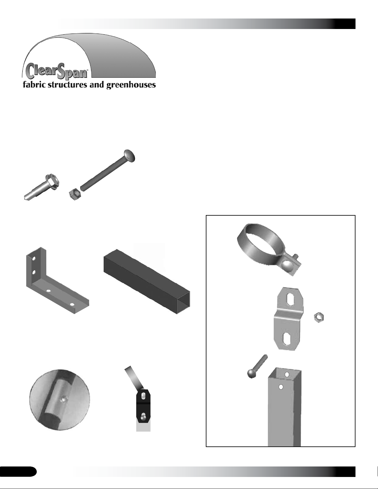
The following graphics and photos will help you identify the
different parts. (Some parts are not shown.)
FA4482B
Tek Screw
QH1330
Angled Bracket
FALB32B & FAH320B
Nut and Carriage Bolt
1.75" x 1.75" Square Tube
104075
Band Clamp
FALB32B
5/16" Nut
104074
FAH320B
2-1/2"
Carriage
Bolt
4
CC6213
Fabric Clip
104074
Square-to-Round Tube
Bracket
End Frame
Square Tube
End Frame-to-Rafter Exploded View
Revision date: 09.13.10

OVERVIEW
This section describes assembling your end frame kit. For
details, please see section "Assembling the End Frame Kit
Components." See illustration below to identify main parts
of end frame kit.
Locate the required parts for each assembly procedure.1.
Prepare and secure posts for the door framing. 2.
(See Front Profile diagrams.)
Assemble and attach all end framing.3.
CLEARSPAN™ END WALL FRAMING KITS
ClearSpan™
End Frame Kit
ATTENTION: End frame spacing depends on the door sizes
and may differ from what is shown in these diagrams. Consult
the Front Profile diagrams in the Quick Start section for pipe
identifications and locations.
Prepare and attach end panel (if equipped). 4.
NOTE: Rafter and struts are not included with kit.
Secure the band clamp
to the rafter using a Tek
screw as shown.
The 2" x 2"
door frame
tubes are
joined using
a 104075
insert and
Tek screws.
ATTENTION: If you are installing an overhead door, do not
attach framing within the door opening.
Revision date: 09.13.10
Ground Level
5
CLEARSPAN™ END WALL FRAMING KITS
ASSEMBLING THE END FRAME KIT COMPONENTS
Consult the end wall diagrams in the Quick Start section of
these instructions before you begin.
ATTENTION: If the main cover is installed, loosen the two
(2) main cover bonnet ratchets at the end of the shelter
where the end wall will be installed. If an end panel is to
be installed, remove the ratchets to install the end panel
frame. The ratchets are reattached after the end frame is
installed.
Assistance is required to assemble the end wall. Lifts
designed to reach the top of the end rafter are also needed.
Consult a qualified construction professional if you are not
familiar with the construction of similar frame structures.
Install the Ground Posts for Door Frame (Jambs)
The following steps describe one way to set the ground posts for the door frame tubes.
At ground level, measure 1. between the legs of the end rafter to locate the center of the end wall. Use a plumb line to
identify the center of the overhead rafter and mark that location on the ground as well.
NOTE: Marking the center of the end wall allows multiple measurements to be made as needed.
Sample Frame
Ground Level
ATTENTION: If you are installing an overhead door, do not
attach framing within the door opening.
Using the dimensions on the Front Profile diagrams, locate the positions of the2. door jambs for the door (if equipped).
The width of the door determines the frame dimensions for the door opening. Consult the documentation sent with the
door for the correct spacing of the door jambs.
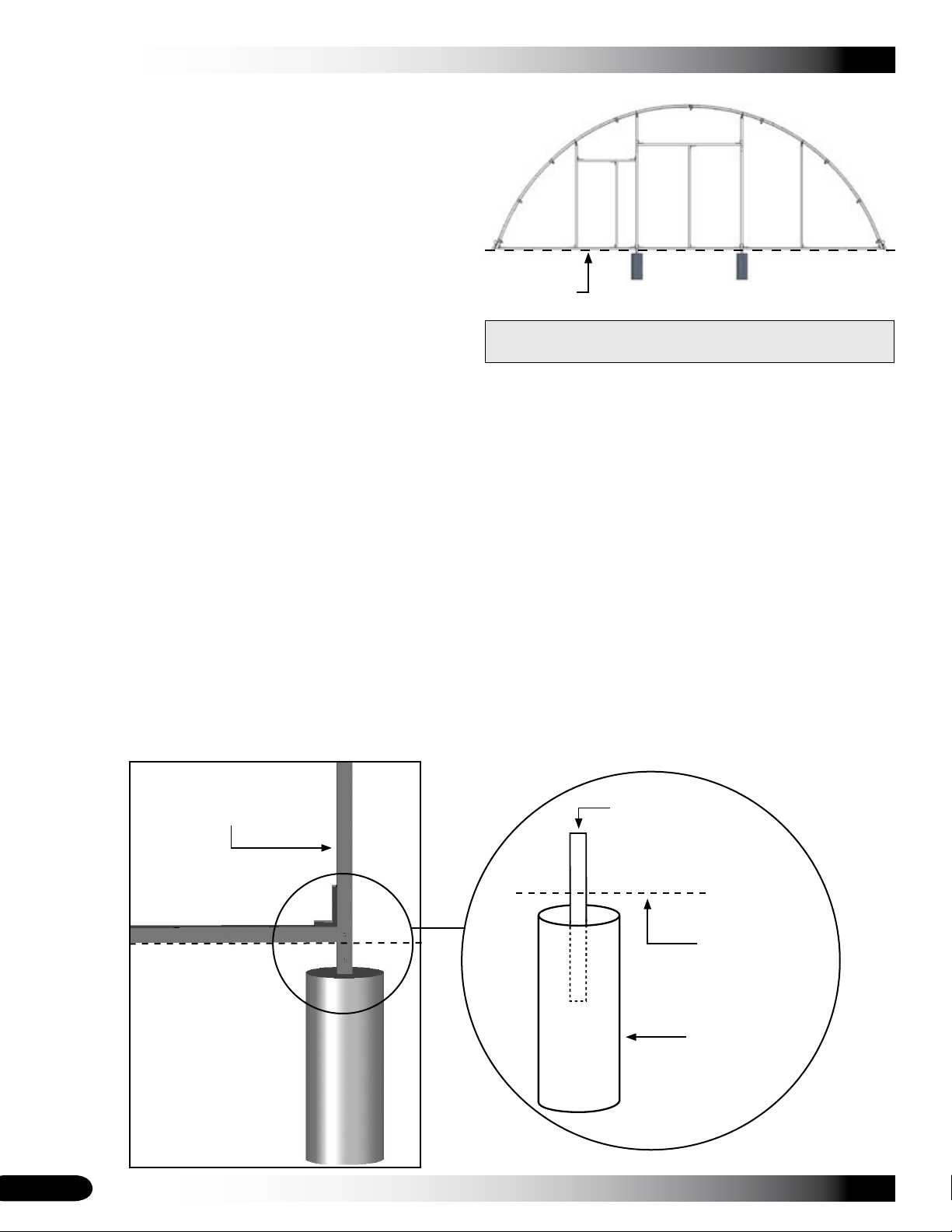
Dig a 12" diameter hole 3. at the locations found in previous step to a depth that is below the geographic frost line.
Add concrete to the hole. Concrete should remain 1" to 2" below ground level so that it does not interfere with 4.
construction and installation of other end wall components.
Determine the required width of the door (if equipped) and insert one 1.75" x 1.75" square tube (104075) into the 5.
concrete approximately 8". See diagram below. Repeat the step and verify that the tubes are plumb and the correct
distance apart. End frame diagrams shown in these instructions may show a door opening with different dimensions.
Section of the assembled
End Wall Frame.
*1.75" x 1.75" square
tube (104075): Half in
the concrete and half
exposed.
Ground Level
Concrete
*Not shown to scale.
6
Revision date: 09.13.10
 Loading...