

Page 1
CONVERGE™ PRO 880
CONVERGE™ SR 1212
Professional Conferencing Systems
|
880T | 880TA | 840T | 8i | TH20
|
SR 1212A
|
INSTALLATION & OPERATION MANUAL
Page 2

TECHNICAL SUPPORT
Telephone 1.800.283.5936
1.801.974.3760
Fax 1.801.977.0087
Email tech.support@clearone.com
Web www.clearone.com
CONVERGE PRO 880/880T/880TA/840T/8i, CONVERGE
SR 1212/SR 1212TA
INSTALLATION & OPERATION MANUAL
CLEARONE PART NO. 800-151-880 (REVISION 3.2) April 2009
© 2009 ClearOne Communications, Inc. All rights reserved. Information in
this document is subject to change without notice. Other product names may
be registered trademarks of their respective owners who do not necessarily
endorse ClearOne or ClearOne’s products in the United States and/or other
countries.
ClearOne Document: 800-151-880 Revision 3.2 April 2009.
Adobe® Flash® Copyright and Trademark Notice
Adobe® Flash® Player. Copyright © 1996 – 2009 Adobe Systems Incorporated.
All Rights Reserved. Adobe and Flash are either trademarks or registered
trademarks in the United States and/or other countries.
Page 3

TABLE OF CONTENTS
CHAPTER 1: INTRODUCTION 1
Converge Pro Product Family Overview. . . . . . . . . . . . . . . . . . . . . . . . . . . . . . . . . . . . . . . . . . . . . . . . . . . . . . 1
Important safety information. . . . . . . . . . . . . . . . . . . . . . . . . . . . . . . . . . . . . . . . . . . . . . . . . . . . . . . . . . . . . . . 4
Converge Pro Product Descriptions. . . . . . . . . . . . . . . . . . . . . . . . . . . . . . . . . . . . . . . . . . . . . . . . . . . . . . . . . 6
Customer Service and Support . . . . . . . . . . . . . . . . . . . . . . . . . . . . . . . . . . . . . . . . . . . . . . . . . . . . . . . . . . . 13
Product Registration . . . . . . . . . . . . . . . . . . . . . . . . . . . . . . . . . . . . . . . . . . . . . . . . . . . . . . . . . . . . . . . . . . . . 13
Warranty Information. . . . . . . . . . . . . . . . . . . . . . . . . . . . . . . . . . . . . . . . . . . . . . . . . . . . . . . . . . . . . . . . . . . . 13
Operating Requirements. . . . . . . . . . . . . . . . . . . . . . . . . . . . . . . . . . . . . . . . . . . . . . . . . . . . . . . . . . . . . . . . . 14
System Requirements. . . . . . . . . . . . . . . . . . . . . . . . . . . . . . . . . . . . . . . . . . . . . . . . . . . . . . . . . . . . . . . . . . . 14
Unpacking. . . . . . . . . . . . . . . . . . . . . . . . . . . . . . . . . . . . . . . . . . . . . . . . . . . . . . . . . . . . . . . . . . . . . . . . . . . . 15
Controls and Connections . . . . . . . . . . . . . . . . . . . . . . . . . . . . . . . . . . . . . . . . . . . . . . . . . . . . . . . . . . . . . . . 23
CHAPTER 2: EXPANSION BUS & LCD PROGRAMMING 30
Expansion Bus . . . . . . . . . . . . . . . . . . . . . . . . . . . . . . . . . . . . . . . . . . . . . . . . . . . . . . . . . . . . . . . . . . . . . . . . 30
Device IDs. . . . . . . . . . . . . . . . . . . . . . . . . . . . . . . . . . . . . . . . . . . . . . . . . . . . . . . . . . . . . . . . . . . . . . . . . . . . 31
LCD Programming Overview . . . . . . . . . . . . . . . . . . . . . . . . . . . . . . . . . . . . . . . . . . . . . . . . . . . . . . . . . . . . . 32
LCD Channels Menu. . . . . . . . . . . . . . . . . . . . . . . . . . . . . . . . . . . . . . . . . . . . . . . . . . . . . . . . . . . . . . . . . . . . 36
LCD Settings Menu. . . . . . . . . . . . . . . . . . . . . . . . . . . . . . . . . . . . . . . . . . . . . . . . . . . . . . . . . . . . . . . . . . . . . 37
LCD Macros Menu . . . . . . . . . . . . . . . . . . . . . . . . . . . . . . . . . . . . . . . . . . . . . . . . . . . . . . . . . . . . . . . . . . . . . 39
LCD Preset Menu . . . . . . . . . . . . . . . . . . . . . . . . . . . . . . . . . . . . . . . . . . . . . . . . . . . . . . . . . . . . . . . . . . . . . . 40
CHAPTER 3: CONVERGE CONSOLE PROGRAMMING 41
Installing Converge Console. . . . . . . . . . . . . . . . . . . . . . . . . . . . . . . . . . . . . . . . . . . . . . . . . . . . . . . . . . . . . . 41
Converge Console Overview . . . . . . . . . . . . . . . . . . . . . . . . . . . . . . . . . . . . . . . . . . . . . . . . . . . . . . . . . . . . . 44
Site File Overview . . . . . . . . . . . . . . . . . . . . . . . . . . . . . . . . . . . . . . . . . . . . . . . . . . . . . . . . . . . . . . . . . . . . . . 49
Connect to a Site . . . . . . . . . . . . . . . . . . . . . . . . . . . . . . . . . . . . . . . . . . . . . . . . . . . . . . . . . . . . . . . . . . . . . . 52
Site Properties. . . . . . . . . . . . . . . . . . . . . . . . . . . . . . . . . . . . . . . . . . . . . . . . . . . . . . . . . . . . . . . . . . . . . . . . . 53
Unit Properties . . . . . . . . . . . . . . . . . . . . . . . . . . . . . . . . . . . . . . . . . . . . . . . . . . . . . . . . . . . . . . . . . . . . . . . . 58
Configuration Mode Overview . . . . . . . . . . . . . . . . . . . . . . . . . . . . . . . . . . . . . . . . . . . . . . . . . . . . . . . . . . . . 64
Unit Tab . . . . . . . . . . . . . . . . . . . . . . . . . . . . . . . . . . . . . . . . . . . . . . . . . . . . . . . . . . . . . . . . . . . . . . . . . . . . . . 65
Channel Tab Overview . . . . . . . . . . . . . . . . . . . . . . . . . . . . . . . . . . . . . . . . . . . . . . . . . . . . . . . . . . . . . . . . . . 77
AEC (Acoustic Echo Cancellation) . . . . . . . . . . . . . . . . . . . . . . . . . . . . . . . . . . . . . . . . . . . . . . . . . . . . . . . . . 81
NC (Noise Cancellation) . . . . . . . . . . . . . . . . . . . . . . . . . . . . . . . . . . . . . . . . . . . . . . . . . . . . . . . . . . . . . . . . . 84
Filters. . . . . . . . . . . . . . . . . . . . . . . . . . . . . . . . . . . . . . . . . . . . . . . . . . . . . . . . . . . . . . . . . . . . . . . . . . . . . . . . 86
AGC/ALC (Automatic Gain Control/Automatic Level Control) Tab . . . . . . . . . . . . . . . . . . . . . . . . . . . . . . . . . 91
Mic Gating. . . . . . . . . . . . . . . . . . . . . . . . . . . . . . . . . . . . . . . . . . . . . . . . . . . . . . . . . . . . . . . . . . . . . . . . . . . . 93
Mic Input Settings . . . . . . . . . . . . . . . . . . . . . . . . . . . . . . . . . . . . . . . . . . . . . . . . . . . . . . . . . . . . . . . . . . . . . . 97
Line Input Settings . . . . . . . . . . . . . . . . . . . . . . . . . . . . . . . . . . . . . . . . . . . . . . . . . . . . . . . . . . . . . . . . . . . . 103
Telco RX Settings . . . . . . . . . . . . . . . . . . . . . . . . . . . . . . . . . . . . . . . . . . . . . . . . . . . . . . . . . . . . . . . . . . . . . 108
Output Settings . . . . . . . . . . . . . . . . . . . . . . . . . . . . . . . . . . . . . . . . . . . . . . . . . . . . . . . . . . . . . . . . . . . . . . . 117
Telco TX Settings. . . . . . . . . . . . . . . . . . . . . . . . . . . . . . . . . . . . . . . . . . . . . . . . . . . . . . . . . . . . . . . . . . . . . . 122
Processing Settings . . . . . . . . . . . . . . . . . . . . . . . . . . . . . . . . . . . . . . . . . . . . . . . . . . . . . . . . . . . . . . . . . . . 128
Fader Settings. . . . . . . . . . . . . . . . . . . . . . . . . . . . . . . . . . . . . . . . . . . . . . . . . . . . . . . . . . . . . . . . . . . . . . . . 136
Matrix Tab . . . . . . . . . . . . . . . . . . . . . . . . . . . . . . . . . . . . . . . . . . . . . . . . . . . . . . . . . . . . . . . . . . . . . . . . . . . 140
AEC Reference/PA Adapt Reference Tab . . . . . . . . . . . . . . . . . . . . . . . . . . . . . . . . . . . . . . . . . . . . . . . . . . . 144
Macro Tab . . . . . . . . . . . . . . . . . . . . . . . . . . . . . . . . . . . . . . . . . . . . . . . . . . . . . . . . . . . . . . . . . . . . . . . . . . . 147
Gating Tab. . . . . . . . . . . . . . . . . . . . . . . . . . . . . . . . . . . . . . . . . . . . . . . . . . . . . . . . . . . . . . . . . . . . . . . . . . . 151
Control Tab . . . . . . . . . . . . . . . . . . . . . . . . . . . . . . . . . . . . . . . . . . . . . . . . . . . . . . . . . . . . . . . . . . . . . . . . . . 154
Page 4

TABLE OF CONTENTS (continued)
String Tab . . . . . . . . . . . . . . . . . . . . . . . . . . . . . . . . . . . . . . . . . . . . . . . . . . . . . . . . . . . . . . . . . . . . . . . . . . . 157
Event Scheduler Tab . . . . . . . . . . . . . . . . . . . . . . . . . . . . . . . . . . . . . . . . . . . . . . . . . . . . . . . . . . . . . . . . . . . 159
Database Tab . . . . . . . . . . . . . . . . . . . . . . . . . . . . . . . . . . . . . . . . . . . . . . . . . . . . . . . . . . . . . . . . . . . . . . . . 161
Optimizing Gain Structure. . . . . . . . . . . . . . . . . . . . . . . . . . . . . . . . . . . . . . . . . . . . . . . . . . . . . . . . . . . . . . . 166
Drag and Drop Configuration . . . . . . . . . . . . . . . . . . . . . . . . . . . . . . . . . . . . . . . . . . . . . . . . . . . . . . . . . . . . 169
Preset Mode . . . . . . . . . . . . . . . . . . . . . . . . . . . . . . . . . . . . . . . . . . . . . . . . . . . . . . . . . . . . . . . . . . . . . . . . . 175
File Menu Overview. . . . . . . . . . . . . . . . . . . . . . . . . . . . . . . . . . . . . . . . . . . . . . . . . . . . . . . . . . . . . . . . . . . . 182
Print Reports . . . . . . . . . . . . . . . . . . . . . . . . . . . . . . . . . . . . . . . . . . . . . . . . . . . . . . . . . . . . . . . . . . . . . . . . . 184
View Menu Overview. . . . . . . . . . . . . . . . . . . . . . . . . . . . . . . . . . . . . . . . . . . . . . . . . . . . . . . . . . . . . . . . . . . 185
Add Menu . . . . . . . . . . . . . . . . . . . . . . . . . . . . . . . . . . . . . . . . . . . . . . . . . . . . . . . . . . . . . . . . . . . . . . . . . . . 187
Connect Menu Overview. . . . . . . . . . . . . . . . . . . . . . . . . . . . . . . . . . . . . . . . . . . . . . . . . . . . . . . . . . . . . . . . 190
Modes Menu Overview . . . . . . . . . . . . . . . . . . . . . . . . . . . . . . . . . . . . . . . . . . . . . . . . . . . . . . . . . . . . . . . . . 191
Services Menu Overview. . . . . . . . . . . . . . . . . . . . . . . . . . . . . . . . . . . . . . . . . . . . . . . . . . . . . . . . . . . . . . . . 192
Dialer. . . . . . . . . . . . . . . . . . . . . . . . . . . . . . . . . . . . . . . . . . . . . . . . . . . . . . . . . . . . . . . . . . . . . . . . . . . . . . . 193
Phonebook . . . . . . . . . . . . . . . . . . . . . . . . . . . . . . . . . . . . . . . . . . . . . . . . . . . . . . . . . . . . . . . . . . . . . . . . . . 195
Label Editor. . . . . . . . . . . . . . . . . . . . . . . . . . . . . . . . . . . . . . . . . . . . . . . . . . . . . . . . . . . . . . . . . . . . . . . . . . 197
Device Log . . . . . . . . . . . . . . . . . . . . . . . . . . . . . . . . . . . . . . . . . . . . . . . . . . . . . . . . . . . . . . . . . . . . . . . . . . 198
Event Log . . . . . . . . . . . . . . . . . . . . . . . . . . . . . . . . . . . . . . . . . . . . . . . . . . . . . . . . . . . . . . . . . . . . . . . . . . . 201
Web Builder. . . . . . . . . . . . . . . . . . . . . . . . . . . . . . . . . . . . . . . . . . . . . . . . . . . . . . . . . . . . . . . . . . . . . . . . . . 203
Firmware Loader. . . . . . . . . . . . . . . . . . . . . . . . . . . . . . . . . . . . . . . . . . . . . . . . . . . . . . . . . . . . . . . . . . . . . . 208
Debug Console. . . . . . . . . . . . . . . . . . . . . . . . . . . . . . . . . . . . . . . . . . . . . . . . . . . . . . . . . . . . . . . . . . . . . . . 210
Execute Presets . . . . . . . . . . . . . . . . . . . . . . . . . . . . . . . . . . . . . . . . . . . . . . . . . . . . . . . . . . . . . . . . . . . . . . 216
APPENDIX A: SERIAL COMMAND GUIDE 218
Type and Device IDs . . . . . . . . . . . . . . . . . . . . . . . . . . . . . . . . . . . . . . . . . . . . . . . . . . . . . . . . . . . . . . . . . . . 218
Conventions . . . . . . . . . . . . . . . . . . . . . . . . . . . . . . . . . . . . . . . . . . . . . . . . . . . . . . . . . . . . . . . . . . . . . . . . . 218
Command Form Description . . . . . . . . . . . . . . . . . . . . . . . . . . . . . . . . . . . . . . . . . . . . . . . . . . . . . . . . . . . . 218
Groups and Channels. . . . . . . . . . . . . . . . . . . . . . . . . . . . . . . . . . . . . . . . . . . . . . . . . . . . . . . . . . . . . . . . . . 219
Meter Type Definitions Table . . . . . . . . . . . . . . . . . . . . . . . . . . . . . . . . . . . . . . . . . . . . . . . . . . . . . . . . . . . . . 220
Serial Commands . . . . . . . . . . . . . . . . . . . . . . . . . . . . . . . . . . . . . . . . . . . . . . . . . . . . . . . . . . . . . . . . . . . . . 227
APPENDIX B: DEFAULT PINOUTS 280
Control/Status Ports . . . . . . . . . . . . . . . . . . . . . . . . . . . . . . . . . . . . . . . . . . . . . . . . . . . . . . . . . . . . . . . . . . . 280
All Models: RS-232 Port . . . . . . . . . . . . . . . . . . . . . . . . . . . . . . . . . . . . . . . . . . . . . . . . . . . . . . . . . . . . . . . . 286
APPENDIX C: FIRMWARE LOADING PROCEDURE 287
APPENDIX C: SPECIFICATIONS 288
Converge Pro 880. . . . . . . . . . . . . . . . . . . . . . . . . . . . . . . . . . . . . . . . . . . . . . . . . . . . . . . . . . . . . . . . . . . . . 288
Converge Pro 880T. . . . . . . . . . . . . . . . . . . . . . . . . . . . . . . . . . . . . . . . . . . . . . . . . . . . . . . . . . . . . . . . . . . . 290
Converge Pro 880TA. . . . . . . . . . . . . . . . . . . . . . . . . . . . . . . . . . . . . . . . . . . . . . . . . . . . . . . . . . . . . . . . . . . 292
Converge Pro 840T . . . . . . . . . . . . . . . . . . . . . . . . . . . . . . . . . . . . . . . . . . . . . . . . . . . . . . . . . . . . . . . . . . . 294
Converge Pro 8i . . . . . . . . . . . . . . . . . . . . . . . . . . . . . . . . . . . . . . . . . . . . . . . . . . . . . . . . . . . . . . . . . . . . . . 296
CONVERGE PRO 8i (continued) . . . . . . . . . . . . . . . . . . . . . . . . . . . . . . . . . . . . . . . . . . . . . . . . . . . . . . . . . 297
Converge Pro TH20 . . . . . . . . . . . . . . . . . . . . . . . . . . . . . . . . . . . . . . . . . . . . . . . . . . . . . . . . . . . . . . . . . . . 298
Converge SR 1212 . . . . . . . . . . . . . . . . . . . . . . . . . . . . . . . . . . . . . . . . . . . . . . . . . . . . . . . . . . . . . . . . . . . . 299
Converge SR 1212A . . . . . . . . . . . . . . . . . . . . . . . . . . . . . . . . . . . . . . . . . . . . . . . . . . . . . . . . . . . . . . . . . . . 301
APPENDIX D: COMPLIANCE 303
FCC Part 15/ICES-003 Compliance . . . . . . . . . . . . . . . . . . . . . . . . . . . . . . . . . . . . . . . . . . . . . . . . . . . . . . . 303
FCC Part 68 Compliance . . . . . . . . . . . . . . . . . . . . . . . . . . . . . . . . . . . . . . . . . . . . . . . . . . . . . . . . . . . . . . . 303
Page 5

TABLE OF CONTENTS (continued)
Electrical Safety Advisory . . . . . . . . . . . . . . . . . . . . . . . . . . . . . . . . . . . . . . . . . . . . . . . . . . . . . . . . . . . . . . . 304
IC COMPLIANCE . . . . . . . . . . . . . . . . . . . . . . . . . . . . . . . . . . . . . . . . . . . . . . . . . . . . . . . . . . . . . . . . . . . . . 304
EUROPEAN COMPLIANCE . . . . . . . . . . . . . . . . . . . . . . . . . . . . . . . . . . . . . . . . . . . . . . . . . . . . . . . . . . . . . 305
EUROPEAN COMPLIANCE . . . . . . . . . . . . . . . . . . . . . . . . . . . . . . . . . . . . . . . . . . . . . . . . . . . . . . . . . . . . . 307
NEW ZEALAND COMPLIANCE . . . . . . . . . . . . . . . . . . . . . . . . . . . . . . . . . . . . . . . . . . . . . . . . . . . . . . . . . . 309
JAPANESE COMPLIANCE . . . . . . . . . . . . . . . . . . . . . . . . . . . . . . . . . . . . . . . . . . . . . . . . . . . . . . . . . . . . . . 309
GLOSSARY 310
Page 6

CHAPTER 1: INTRODUCTION
CONVERGE PRO PRODUCT FAMILY OVERVIEW
Congratulations! You have purchased a ClearOne® Converge™ Pro audio conferencing solution. The Converge Pro
product family represents a revolutionary advance in state-of-the-art audio technology for large-scale conferencing
applications.
ClearOne introduced its first audio conferencing products to the market in 1990 under the brand name Gentner®.
Today, ClearOne has over 80,000 installations worldwide in organizations ranging from the Fortune 1,000 to the
federal government. ClearOne products are used in the most demanding conferencing applications, where they
consistently deliver industry-leading audio quality and unsurpassed reliability.
ClearOne’s proprietary Distributed Echo Cancellation (DEC) technology forms the foundation of the Converge Pro
product family, and provides optimal audio quality for today’s distributed conferencing environments. In addition
to DEC, other ClearOne innovations – including noise cancellation, automatic gain and level control, advanced
microphone gating, adaptive ambient, and ClearEffect™ wideband audio emulation – produce crystal-clear audio
that is equivalent to conference participants being in the same room.
Applications
The Converge Pro product family provides scalable conferencing solutions for any size venue. Some common
applications include:
Boardrooms•
Training rooms •
Courtrooms•
Multimedia rooms•
Distance learning•
Auditoriums•
Houses of worship•
Sound reinforcement•
Large meeting venues•
1
Page 7

Models
The Converge Pro product family includes the following models:
Converge Pro 880•
Converge Pro 880T•
Converge Pro 880TA •
Converge Pro 840T•
Converge Pro TH20•
Converge Pro 8i•
Converge Pro SR1212•
Converge Pro SR1212A•
Common Benefits
Each product in the Converge Pro product family offers the following benefits:
Superior audio quality•
ClearOne’s next generation signal processing algorithms•
Field-proven conferencing technology•
Flexible configuration and expandability•
Improved configuration and management software•
Simplified programming•
Reduced installation times•
Best-in-class processing speed•
ClearOne’s world-class customer service, technical support, and field engineering services•
Common Features
The leading-edge features common to all products in the Converge Pro family include:
USB connector on front panel for easy connectivity with a laptop or PC•
Dual RJ-45 Ethernet ports•
Dual RJ-45 expansion bus ports•
TDM (Time Division Multiplexed) mix/minus audio and control buses•
RS-232 serial port (up to 115,200 bps)•
Dual DB-25 control/status GPIO (General Purpose Input/Output) Ports•
Mini-phoenix audio input/output connectors (color-coded by channel type)•
Differential inputs and outputs•
Feature Enhancements
Converge Pro feature enhancements include:
ClearOne’s next-generation Distributed Echo Cancellation—up to eight discrete digital signal processors •
(DSPs) improve full-duplex performance and remove echo in the most difficult acoustic environments.
New PTT (Push-to-Talk) microphone compatibility provides greater design and configuration flexibility.•
Advanced noise cancellation reduces background noise caused by fans, HVAC systems, and other relatively •
constant background noise sources.
Up to eight independent signal processing blocks, each with 15 user-configurable filters (including all-pass, •
low-pass, high-pass, low-shelving, high-shelving, and parametric), delay, and compression. ClearOne’s
unparalleled processing power enables you to use all of these features simultaneously in any combination,
allowing you to create optimized audio configurations for every environment and application.
Enhanced expansion bus (E-bus) capabilities—connect up to 34 Converge Pro units together and use up to •
2
Page 8

96 microphones and 16 telephone lines in a single Converge Pro installation.
Increased distance between units—up to 200 feet/60.96 meters.•
Graphical, user-configurable routing matrix allows you to route any input channel to any output, processing, •
or fader channel (or combination thereof) on any Converge Pro unit, or across the expansion bus.
Front panel control of mute and gain for all input and output channels.•
Safety mute button on the Console™ software button bar instantly mutes all outputs.•
ClearOne’s DSP (Digital Signal Processing) technology ensures crystal-clear audio between conferencing •
sites.
AEC (Acoustical Echo Cancellation) Enhancements
Smoothing filters to reduce artifacts•
Pre-AEC bypass channels•
Improved AEC adaption and noise suppression algorithms•
Automated Push-to-Talk microphone mode with AEC freezing•
Gain and gating control tracking•
Cross point gain adjustments•
Four fader channels•
Microphone preamp gain control•
7 dB coarse gain and .5 dB fine gain increments for improved microphone gain matching•
AGC (Automatic Gain Control) algorithm•
ALC (Automatic Level Control) algorithm•
Telephone Hybrid Enhancements (880T, 880TA, 840T, TH20)
Custom telephone line settings for international teleconferencing and in-country localization•
Type I & Type II auto-sensing telephone interface (U.S. and E.U.)•
International impedance matching•
Improved TEC (Telco Echo Cancellation) with 31 millisecond tail time•
Continual TEC adaptation to telephone line conditions•
ClearEffect™ wideband audio emulation algorithm•
Digital anti-alias filter minimizes CO switching noise and hum•
ALC (Automatic Level Control) on telco receive channel•
Improved call management and processing•
Adjustable dial tone, DTMF attenuation•
Off-hook DTMF generation•
Robust dial tone detection•
Caller ID & selectable ringers•
Touch-tone dialing capability (44 character dial string)•
Analog telephone line compatibility•
10 W speaker amplifier (880T, 880TA, 840T)•
Custom ring cadence detect•
3
Page 9

IMPORTANT SAFETY INFORMATION
AVIS: RISQUE DE CHOC
ELECTRIQUE - NE PAS OUVRIR
Read all safety information before using this product.
Read these instructions.1.
Keep these instructions.2.
Heed all warnings.3.
Follow all instructions.4.
Do not use this apparatus near water.5.
Clean only with dry cloth.6.
Do not block any ventilation openings. Install in accordance with the manufacturer’s instructions.7.
Do not install near any heat sources such as radiators, heat registers, stoves, or other apparatus (including 8.
amplifiers) that produce heat.
Do not defeat the safety purpose of the polarized or grounding-type plug. A polarized plug has two blades 9.
with one wider than the other. A grounding type plug has two blades and a third grounding prong. The wide
blade or the third prong are provided for your safety. If the provided plug does not fit into your outlet, consult
an electrician for replacement of the obsolete outlet. Apparatet skal tilkoples jordet stikkontakt.
Protect the power cord from being walked on or pinched particularly at plugs, convenience receptacles, and 10.
the point where they exit from the apparatus.
Only use attachments/accessories specified by the manufacturer.11.
Use only with the cart, stand, tripod, bracket, or table specified by the manufacturer, or sold with the 12.
apparatus. When a cart is used, use caution when moving the cart/apparatus combination to avoid injury
from tip-over.
Unplug this apparatus during lightning storms or when unused for long periods of time.13.
Refer all servicing to qualified service personnel. Servicing is required when the apparatus has been 14.
damaged in any way, such as power-supply cord or plug is damaged, liquid has been spilled or objects have
fallen into the apparatus, the apparatus has been exposed to rain or moisture, does not operate normally, or
has been dropped.
Use the mains plug to disconnect the apparatus from the AC mains. The mains plug shall remain readily 15.
operable.
On/Off switch located on the front panel of the Converge Pro 880TA and SR 1212A does NOT disconnect 16.
power from the AC mains.
To completely disconnect unit power from the AC mains, disconnect the unit’s power cord from the mains 17.
socket. To reconnect power, plug the unit’s power cord into the mains socket following all safety instructions
and guidelines.
Caution: Danger of explosion if lithium battery is incorrectly displaced. Replace only with the same or 18.
equivalent type. Battery should only be replaced by qualified personnel and is not intended as a user
serviceable part. Do not expose batteries or battery pack to excessive heat such as prolonged sunlight, fire
or other heat sources.
Never push objects of any kind into this product through cabinet slots as they may touch dangerous voltage 19.
points or short out parts that could result in fire or electric shock.
This product can interfere with electrical equipment such as tape recorders, TV sets, radios, computers and 20.
microwave ovens if placed in close proximity.
Class 2 Wiring 21. IS REQUIRED for these devices. Wiring and install should only be performed by qualified
personnel.
4
Save These Instructions
Page 10

Converge Pro 880TA
The 880TA stands as the new flagship of the Converge Pro line. Re-designed, re-tooled with added power and
functionality, the 880TA also provides industry-leading expansion capabilities. (Add)
Advanced Telephone Conferencing Feature Set
Signal Processing Improvements•
Telephone noise cancellation (receive channel) »
ClearEffect wideband emulation for speech enhancement »
Automatic level control (receive channel) »
Caller ID & selectable ringers »
Custom ring cadence detect »
Advanced Conferencing Feature Set
Enhanced Feedback Canceller•
Multichannel Control on each amplifier•
Next-generation Acoustic Echo Cancellation•
Improved duplex performance »
Push-to-talk microphone compatibility »
Next-generation Noise Cancellation•
Adaptive modeling to room ambient noise conditions »
Pre-AEC routing for sound reinforcement applications•
A maximum processing delay of four (4) milliseconds »
Management Improvements•
Integrated Ethernet and USB connections »
SNMP and HTML remote management agents with SMTP email alerts »
Web-based user and management control consoles »
Event scheduler »
Diagnostic console »
Simplified Configuration Software•
Drag & drop A/V and channel objects »
Selectable Console views—Unit, Matrix, and Channel »
Superior Audio Performance
Next-generation Distributed Echo Cancellation on every microphone input•
First-microphone priority delivers clear audio to the far end•
20Hz – 22kHz bandwidth for full-range audio response•
AGC & ALC to keep all participants’ audio levels balanced and consistent•
Configuration Flexibility
Scalable—link up to 34 Converge Pro units together for up to 96 microphones and 16 telephone lines•
18 expansion busses »
Enhanced expansion bus, featuring 18 mix-minus audio buses for routing between units•
Ten microphone gating groups (four internal & six global) allow separation of microphones into individual •
mixer gating groups for greater configuration flexibility
32 user-programmable presets can each be executed without disturbing other ongoing preset operations•
255 Macros for customized audio control and configuration using a single command•
5
Page 11

CONVERGE PRO PRODUCT DESCRIPTIONS
Converge Pro 880
The successor to the industry-leading XAP® 800. The 880 delivers rich functionality with improved audio
performance, enhanced management, and simplified configuration for audio conferencing and sound reinforcement
applications.
Advanced Conferencing Feature Set
Next-generation Acoustic Echo Cancellation•
Improved duplex performance »
Push-to-talk microphone compatibility »
Next-generation Noise Cancellation•
Adaptive modeling to room ambient noise conditions »
Increased resolution on Microphone Preamp stage•
0 – 56dB in 7dB increments »
Pre-AEC routing for sound reinforcement applications•
A maximum processing delay of four (4) milliseconds »
Management Improvements•
Integrated Ethernet and USB connections »
SNMP and HTML remote management agents with SMTP email alerts »
Web-based user and management control consoles »
Event scheduler »
Diagnostic console »
Simplified Configuration Software•
Drag & drop A/V and channel objects »
Selectable Console views—Unit, Matrix, and Channel »
Expanded serial command set•
Superior Audio Performance
Next-generation Distributed Echo Cancellation on every microphone input•
First-microphone priority delivers clear audio to the far end•
20Hz – 22kHz bandwidth for full-range audio response•
AGC & ALC to keep all participants’ audio levels balanced and consistent•
Configuration Flexibility
Scalable• —link up to 34 Converge Pro units together for up to 96 microphones and 16 telephone lines
Enhanced expansion bus, featuring 18 mix/minus audio buses for routing between units•
Ten microphone gating groups (four internal & six global) allow separation of microphones into individual •
mixer gating groups for greater configuration flexibility
32 user-programmable presets can each be executed without disturbing other ongoing preset operations•
255 Macros for customized audio control and configuration using a single command•
6
Page 12

Converge Pro 880T
The 880T leverages the rich functionality of the Converge Pro 880, and adds a built-in telephone interface and power
amplifier for standalone conferencing applications. The 880T also provides industry-leading expansion capabilities,
allowing you to connect it with other Converge Pro units for complex installations.
Advanced Telephone Conferencing Feature Set
Signal Processing Improvements•
Telephone noise cancellation (receive channel) »
ClearEffect wideband emulation for speech enhancement »
Automatic level control (receive channel) »
Caller ID & selectable ringers »
Advanced Conferencing Feature Set
Next-generation Acoustic Echo Cancellation•
Improved duplex performance »
Push-to-talk microphone compatibility »
Next-generation Noise Cancellation•
Adaptive modeling to room ambient noise conditions »
Increased resolution on Microphone Preamp stage•
0 – 56dB in 7dB increments »
Pre-AEC routing for sound reinforcement applications•
A maximum processing delay of four (4) milliseconds »
Management Improvements•
Integrated Ethernet and USB connections »
SNMP and HTML remote management agents with SMTP email alerts »
Web-based user and management control consoles »
Event scheduler »
Diagnostic console »
Simplified Configuration Software•
Drag & drop A/V and channel objects »
Selectable Console views—Unit, Matrix, and Channel »
Expanded serial command set•
Superior Audio Performance
Next-generation Distributed Echo Cancellation on every microphone input•
First-microphone priority delivers clear audio to the far end•
20Hz – 22kHz bandwidth for full-range audio response•
AGC & ALC to keep all participants’ audio levels balanced and consistent•
Configuration Flexibility
Scalable—link up to 34 Converge Pro units together for up to 96 microphones and 16 telephone lines•
Enhanced expansion bus, featuring 18 mix-minus audio buses for routing between units•
Ten microphone gating groups (four internal & six global) allow separation of microphones into individual •
mixer gating groups for greater configuration flexibility
32 user-programmable presets can each be executed without disturbing other ongoing preset operations•
255 Macros for customized audio control and configuration using a single command•
7
Page 13

Converge Pro 840T
The successor to the industry-leading XAP 400. The 840T provides the same rich feature set as the 880T, complete
with a built-in telephone interface and power amplifier for standalone conferencing applications. For large venues,
the 840T also provides industry-leading expansion capabilities via ClearOne’s expansion bus technology.
Advanced Telephone Conferencing Feature Set
Signal Processing Improvements•
Telephone noise cancellation (receive channel) »
ClearEffect wideband emulation for speech enhancement »
Automatic level control (receive channel) »
Caller ID & selectable ringers »
Advanced Conferencing Feature Set
Next-generation Acoustic Echo Cancellation•
Improved duplex performance »
Push-to-talk microphone compatibility »
Next-generation Noise Cancellation•
Adaptive modeling to room ambient noise conditions »
Increased resolution on Microphone Preamp stage•
0 – 56dB in 7dB increments »
Pre-AEC routing for sound reinforcement applications•
A maximum processing delay of four (4) milliseconds »
Management Improvements•
Integrated Ethernet and USB connections »
SNMP and HTML remote management agents with SMTP email alerts »
Web-based user and management control consoles »
Event scheduler »
Diagnostic console »
Simplified Configuration Software•
Drag & drop A/V and channel objects »
Selectable Console views—Unit, Matrix, and Channel »
Expanded serial command set•
Superior Audio Performance
Next-generation Distributed Echo Cancellation on every microphone input•
First-microphone priority delivers clear audio to the far end•
20Hz – 22kHz bandwidth for full-range audio response•
AGC & ALC to keep all participants’ audio levels balanced and consistent•
Configuration Flexibility
Scalable—link up to 34 Converge Pro units together for up to 96 microphones and 16 telephone lines•
Enhanced expansion bus, featuring 18 mix-minus audio buses for routing between units•
Eight microphone gating groups (four internal & four global) allow separation of microphones into individual •
mixer gating groups for greater configuration flexibility
32 user-programmable presets can each be executed without disturbing other ongoing preset operations•
255 Macros for customized audio control and configuration using a single command•
8
Page 14

Converge Pro 8i
An input-only expansion box for the Converge Pro platform. The 8i delivers new economical configuration flexibility.
It can be added to 880, 840T, and TH20 systems for additional microphone and line inputs, allowing customers to
match the number of inputs and outputs required for specific conferencing and sound reinforcement installations.
Advanced Conferencing Feature Set
Economical Mic/Line only mixer for large configurations where additional output channels are not required•
Next-generation Acoustic Echo Cancellation•
Improved duplex performance »
Push-to-talk microphone compatibility »
Next-generation Noise Cancellation•
Adaptive modeling to room ambient noise conditions »
Increased resolution on Microphone Preamp stage•
0 – 56dB in 7dB increments »
Pre-AEC routing for sound reinforcement applications•
A maximum processing delay of four (4) milliseconds »
Management Improvements•
Integrated Ethernet and USB connections »
SNMP and HTML remote management agents with SMTP email alerts »
Web-based user and management control consoles »
Event scheduler »
Diagnostic console »
Simplified Configuration Software•
Drag & drop A/V and channel objects »
Selectable Console views—Unit, Matrix, and Channel »
Expanded serial command set•
Superior Audio Performance
Next-generation Distributed Echo Cancellation on every microphone input•
First-microphone priority delivers clear audio to the far end•
20Hz – 22kHz bandwidth for full-range audio response•
AGC & ALC to keep all participants’ audio levels balanced and consistent•
Configuration Flexibility
Scalable• —link up to 34 Converge Pro units together for up to 96 microphones and 16 telephone lines
Enhanced expansion bus, featuring 18 mix-minus audio buses for routing between units•
Ten microphone gating groups (four internal & six global) allow separation of microphones into individual •
mixer gating groups for greater configuration flexibility
32 user-programmable presets can each be executed without disturbing other ongoing preset operations•
255 Macros for customized audio control and configuration using a single command•
9
Page 15

Converge Pro TH20
The successor to the industry-leading XAP TH2, the TH20 enables conference call functionality for Converge Pro
installations through the addition of a telephone interface. The TH20 expansion bus allows you to link up to 16
TH20 units together for industry-leading conferencing capability. It also adds two line-level inputs and outputs for
increased system capacity.
Advanced Telephone Conferencing Feature Set
Signal Processing Improvements•
Telephone noise cancellation (receive channel) »
ClearEffect wideband emulation for speech enhancement »
Automatic level control (receive channel) »
Caller ID »
Selectable ringers »
Increased I/O capabilities•
Two line-level inputs and two line-level outputs »
Audio Expansion bus (E-bus) »
Management Improvements•
Integrated Ethernet and USB connections »
SNMP and HTML remote management agents with SMTP email alerts »
Web-based user and management control consoles »
Event scheduler »
Diagnostic console »
Simplified Configuration Software•
Drag & drop A/V and channel objects »
Selectable Console views—Unit, Matrix, and Channel »
Expanded serial command set•
Superior Audio Performance
Next-generation Distributed Echo Cancellation on every microphone input•
20Hz – 22kHz bandwidth for full-range audio response•
AGC on line inputs to keep gain levels balanced and consistent•
Configuration Flexibility
Scalable• —link up to 34 Converge Pro units together for up to 96 microphones and 16 telephone lines
Enhanced expansion bus, featuring 18 mix-minus audio buses for routing between units•
Eight microphone gating groups (four internal & four global) allow separation of microphones into individual •
mixer gating groups for greater configuration flexibility
32 user-programmable presets can each be executed without disturbing other ongoing preset operations•
255 Macros for customized audio control/configuration with single command execution•
10
Page 16

Converge Pro SR 1212A
The SR1212A is a 12x12 digital matrix mixer that is the ideal solution for sound reinforcement and room combining
applications. In addition to improved audio performance, enhanced management, and simplified configuration, the
SR1212 offers industry-leading expansion capabilties to accomodate virtually any size venue.
Advanced Conferencing Feature Set
Increased resolution on Microphone Preamp stage•
0 – 56dB in 7dB increments »
Management Improvements•
Integrated Ethernet and USB connections »
SNMP and HTML remote management agents with SMTP email alerts »
Web-based user and management control consoles »
Event scheduler »
Diagnostic console »
Simplified Configuration Software•
Drag & drop A/V and channel objects »
Selectable Console views—Unit, Matrix, and Channel »
Expanded serial command set•
Superior Audio Performance
First-microphone priority delivers clear audio to the far end•
20Hz – 22kHz bandwidth for full-range audio response•
AGC & ALC to keep all participants’ audio levels balanced and consistent•
Configuration Flexibility
Scalable• —link up to 34 Converge Pro units together for up to 96 microphones and 16 telephone lines
Enhanced expansion bus, featuring 18 mix/minus audio buses for routing between units•
Eight microphone gating groups (four internal & four global) allow separation of microphones into individual •
gating groups
32 user-programmable presets can each be executed without disturbing other ongoing preset operations•
255 Macros for customized audio control and configuration using a single command•
11
Page 17

Converge Pro SR1212
The successor to ClearOne’s PSR1212, the SR1212 is a 12x12 digital matrix mixer that is the ideal solution for
sound reinforcement and room combining applications. In addition to improved audio performance, enhanced
management, and simplified configuration, the SR1212 offers industry-leading expansion capabilties to accomodate
virtually any size venue.
Advanced Conferencing Feature Set
Increased resolution on Microphone Preamp stage•
0 – 56dB in 7dB increments »
Management Improvements•
Integrated Ethernet and USB connections »
SNMP and HTML remote management agents with SMTP email alerts »
Web-based user and management control consoles »
Event scheduler »
Diagnostic console »
Simplified Configuration Software•
Drag & drop A/V and channel objects »
Selectable Console views—Unit, Matrix, and Channel »
Expanded serial command set•
Superior Audio Performance
First-microphone priority delivers clear audio to the far end•
20Hz – 22kHz bandwidth for full-range audio response•
AGC & ALC to keep all participants’ audio levels balanced and consistent•
Configuration Flexibility
Scalable• —link up to 34 Converge Pro units together for up to 96 microphones and 16 telephone lines
Enhanced expansion bus, featuring 18 mix/minus audio buses for routing between units•
Eight microphone gating groups (four internal & four global) allow separation of microphones into individual •
gating groups
32 user-programmable presets can each be executed without disturbing other ongoing preset operations•
255 Macros for customized audio control and configuration using a single command•
12
Page 18

CUSTOMER SERVICE AND SUPPORT
ClearOne is committed to providing best-in-class customer service and support. If you need assistance installing,
configuring, or operating your Converge Pro system, or if you have questions about ClearOne products or services,
please contact us at one of the locations listed below. ClearOne also welcomes your comments and suggestions.
ClearOne on the Web
Corporate Website: www.clearone.com
Sales Email: sales@clearone.com
Tech Support Email: tech.support@clearone.com
North America (Worldwide Headquarters)
ClearOne Communications
Edgewater Corporate Park, South Tower
5225 Wiley Post Way, Suite 500
Salt Lake City, Utah 84116 USA
Telephone: 801-975-7200
Fax: 801-977-0087
Toll-Free: 800-945-7730
Tech Support: 800-283-5936
Latin America
Telephone: 801-975-7200
Fax: 801-977-0087
Sales Email: sales@clearone.com
Tech Support Email: tech.support@clearone.com
EMEA
Telephone: 44 (0) 1189 036 053
Sales Email: sales@clearone.com
Tech Support Email: tech.support@clearone.com
Asia-Pacific/Japan/Oceania
Telephone: 801-303-3388
Sales Email: sales@clearone.com
Tech Support Email: tech.support@clearone.com
PRODUCT REGISTRATION
Register your Converge Pro product(s) online at http://www.clearone.com/support/registration.php?content=main.
Registering your Converge Pro product(s) enables ClearOne to provide you with better technical assistance, and
to notify you of important information regarding your Converge Pro product including available upgrades, technical
bulletins, and new product information.
WARRANTY INFORMATION
ClearOne Communications, Inc. warrants that this Converge Pro product is free of defects in both material and
workmanship. For complete warranty information including length, coverage, and limitations, visit
http://www.clearone.com/support/warranty.php?content=main
13
Page 19

OPERATING REQUIREMENTS
Power
Converge Pro devices automatically accommodate voltages of 100–240 VAC, 50/60 Hz, 15 W.
Telephone
Converge Pro devices operate on a standard analog telephone line and connect to the telephone system with a
standard RJ-11 modular jack. If you do not have an RJ-11 jack where you want to install your Converge Pro, call
your local telephone company for installation. Converge Pro 840T, 880T, 880TA and TH20 can be configured to meet
compliance requirements of different countries via the Console software.
WARNING: The country code must be set correctly in Console to ensure that the unit operates properly
when connected to the telco network, and that it complies with the country’s telco requirements.
Changing this code to a country other than the intended country of operation might cause Converge Pro
devices to be non-compliant.
Equipment Placement
Converge Pro devices are designed for installation in a standard 19-inch equipment rack.
Environmental
Converge Pro devices are designed to operate at ambient unit temperatures between 14° F (-10° C) and 122° F (50° C).
SYSTEM REQUIREMENTS
The Converge Pro Console software minimum system requirements are:
Supported Operating Systems
Windows XP•
Windows 2000•
Windows Vista•
Minimum System Requirements
Processor: 300 MHz Pentium III (or AMD equivalent)•
RAM: 256 Megabytes RAM•
Video: 1024x768 SVGA (16 bit)•
Hard Drive: 40 Megabytes•
Network: 10/100 Mbps Ethernet•
USB Port: Version 1.0•
CD Drive: CD/DVD ROM•
Minimum Software Requirements
Browser: Microsoft Internet Explorer version 4.0 or higher•
Adobe Flash: Version 9.0 or higher•
Java: Sun Microsystems’ Java Runtime Environment version 6.0 or higher•
14
Page 20
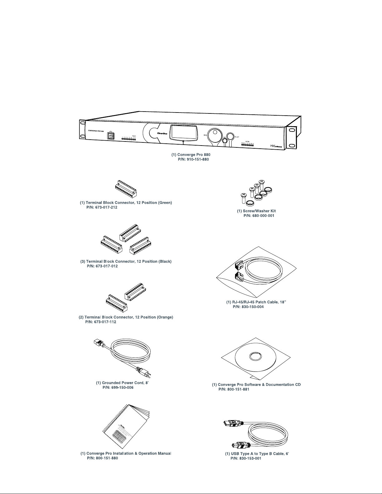
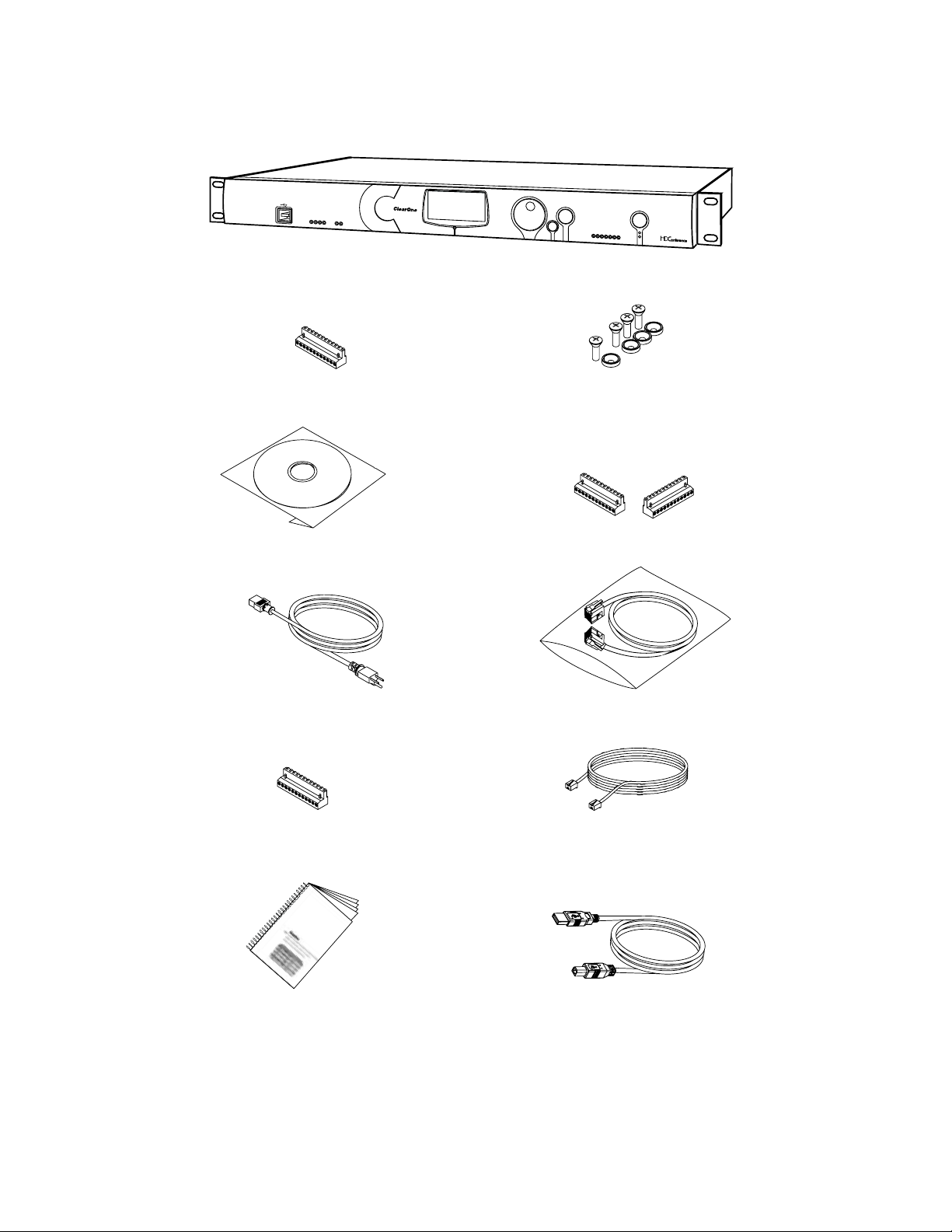
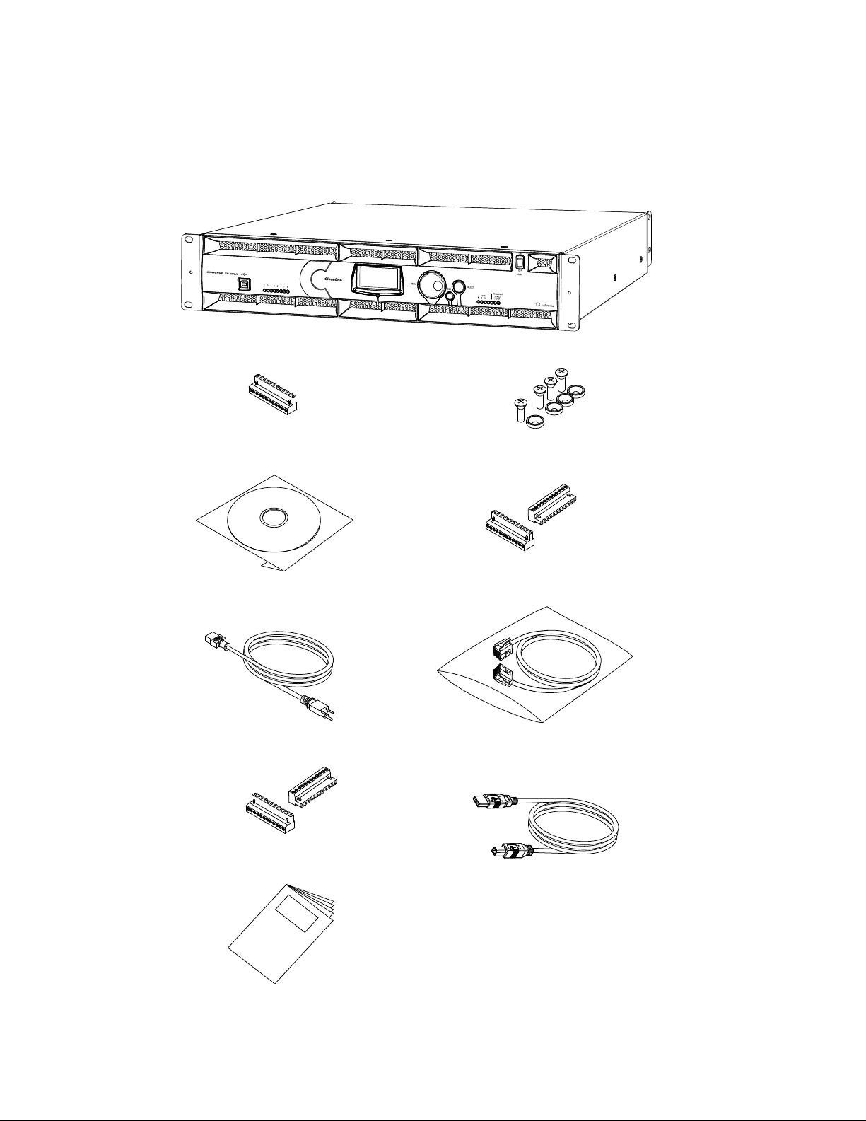
UNPACKING
Use the illustrations below to verify that you received all components for your Converge Pro product. ClearOne is
not responsible for product damage incurred during shipment. Inspect your shipment carefully for obvious signs
of damage. If the shipment appears damaged, retain the original boxes and packing material for inspection by the
carrier, and contact them immediately.
Converge Pro 880 Package Contents
15
Page 21
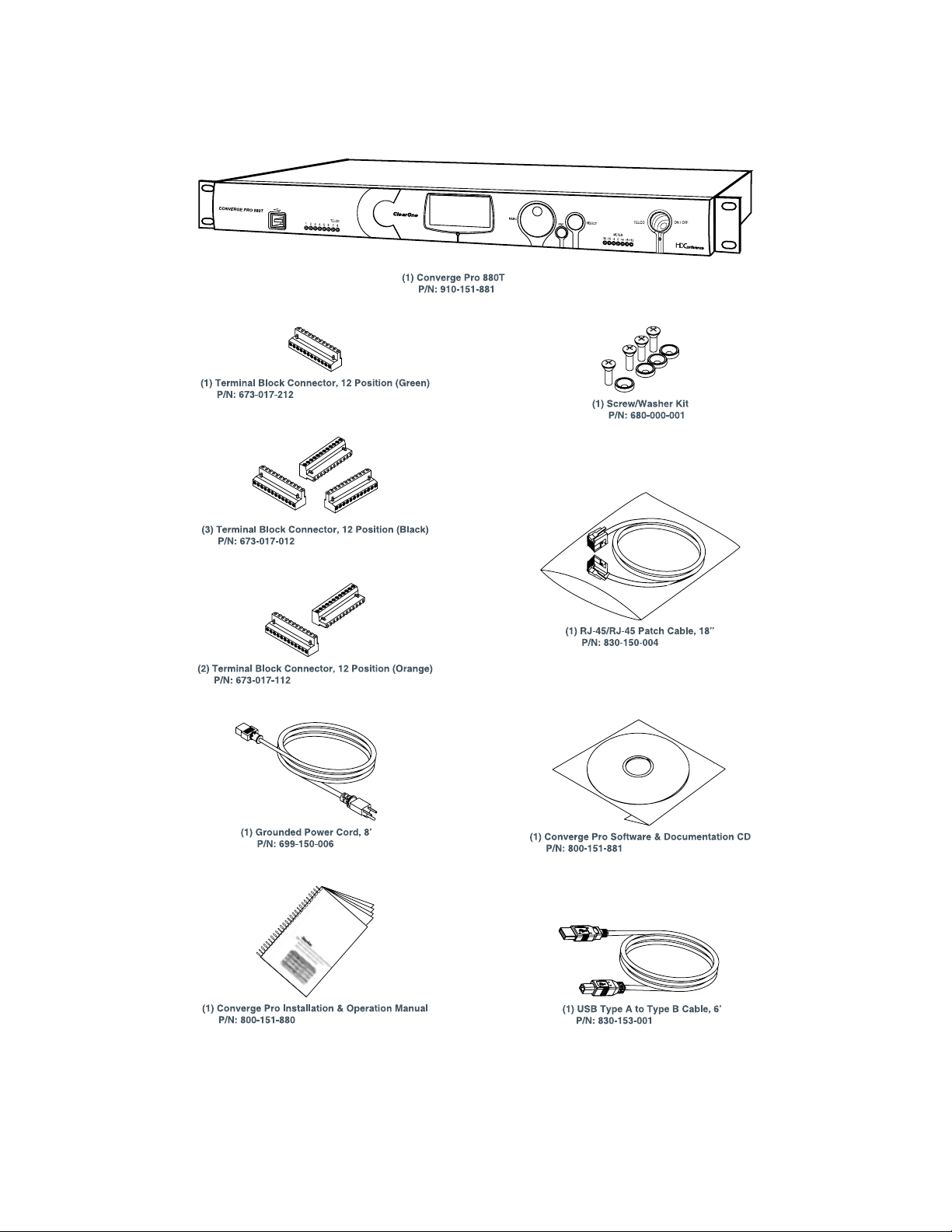
Converge Pro 880T Package Contents
16
Page 22
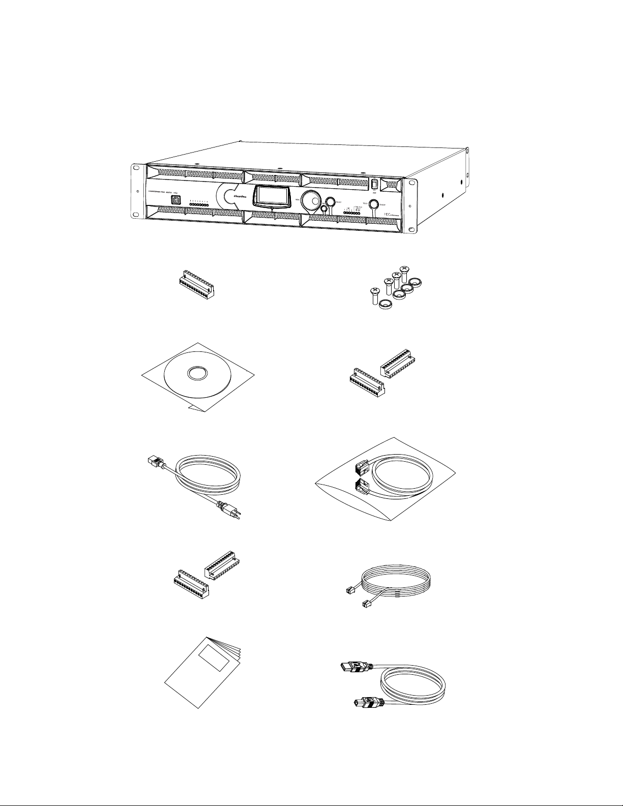
Converge Pro 880TA Package Contents
CABLE ASSEMBLY, RJ45/RJ45 18"
830-150-004 (QTY 1)
CABLE ASSY, TELEPHONE 12FT.
830-000-012 (QTY 1)
MANUAL, CONVERGE 840T
800-151-880 (QTY 1)
CABLE ASSY, USB A-B TYPE 6FT
830-153-001 (QTY 1)
PWR CORD, MOLDED 6' BLK 3 COND
699-150-006 (QTY
1)
CONN, TERM BLOCK/F 12 POS BLACK
673-017-012 (QTY 2)
CONN, TERM BLOCK/F 12 POS ORANGE
673-017-112 (QTY 2)
CONN, TERM BLOCK/F 12 POS GREEN
673-017-212 (QTY 1)
CD, CONVERGE PRO PRODUCT FAMILY
800-151-881 (QTY 1)
SCREW/WASHER ACC KIT, RACK DECOR 4EA BLK
680-000-001 (QTY 1)
Converge Pro 880TA Packing Contents
CONVERGE PRO 880TA (QT Y 1)
17
Page 23
Converge Pro 840T Package Contents
SELECT
TELCO
ON/OFF
MENU
ESC
-30-10 -4 0
+4 +8+12
METER
1234
RX
TX
TELCO
CONVERGE PRO 840T
(1) Converge Pro 840T
P/N: 910-151-840
(1) Installation & Operation Manual
P/N: 800-151-880
(2) Terminal Block Connector, 12 Position (Bla
P/N: 673-017-012
(1) Terminal Block Connector, 12 Position (Orange)
P/N: 673-017-112
(1) Terminal Block Connector, 12 Position (Green)
P/N: 673-017-212
(1) Grounded Power Cord, 8’
P/N: 699-150-006
(1) Software & Documentation CD
P/N: 800-151-881
(1) Screw/Washer Kit
P/N: 680-000-001
(1) RJ-45/RJ-45 Patch Cable, 18”
P/N: 830-150-004
(1) Telephone Cable 12’
P/N:830-000-012
(1) USB Type A to Type B Cable, 6’
P/N: 830-153-001
18
Page 24
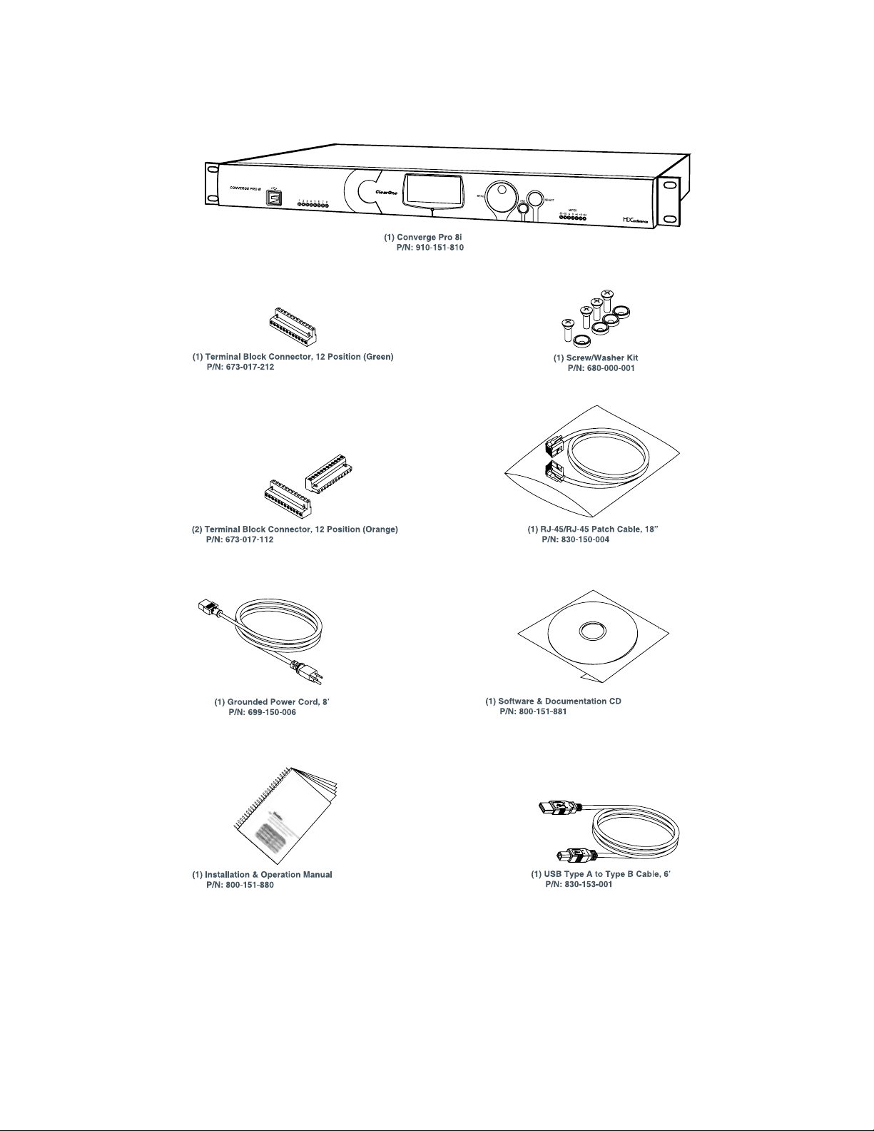
Converge Pro 8i Package Contents
19
Page 25
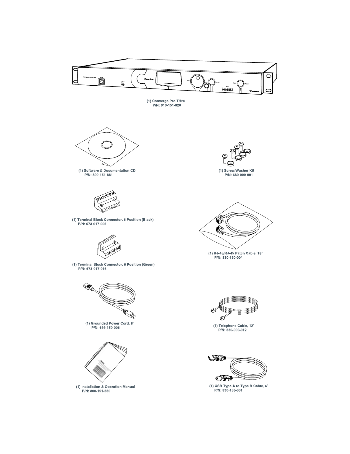
Converge Pro TH20 Package Contents
20
Page 26
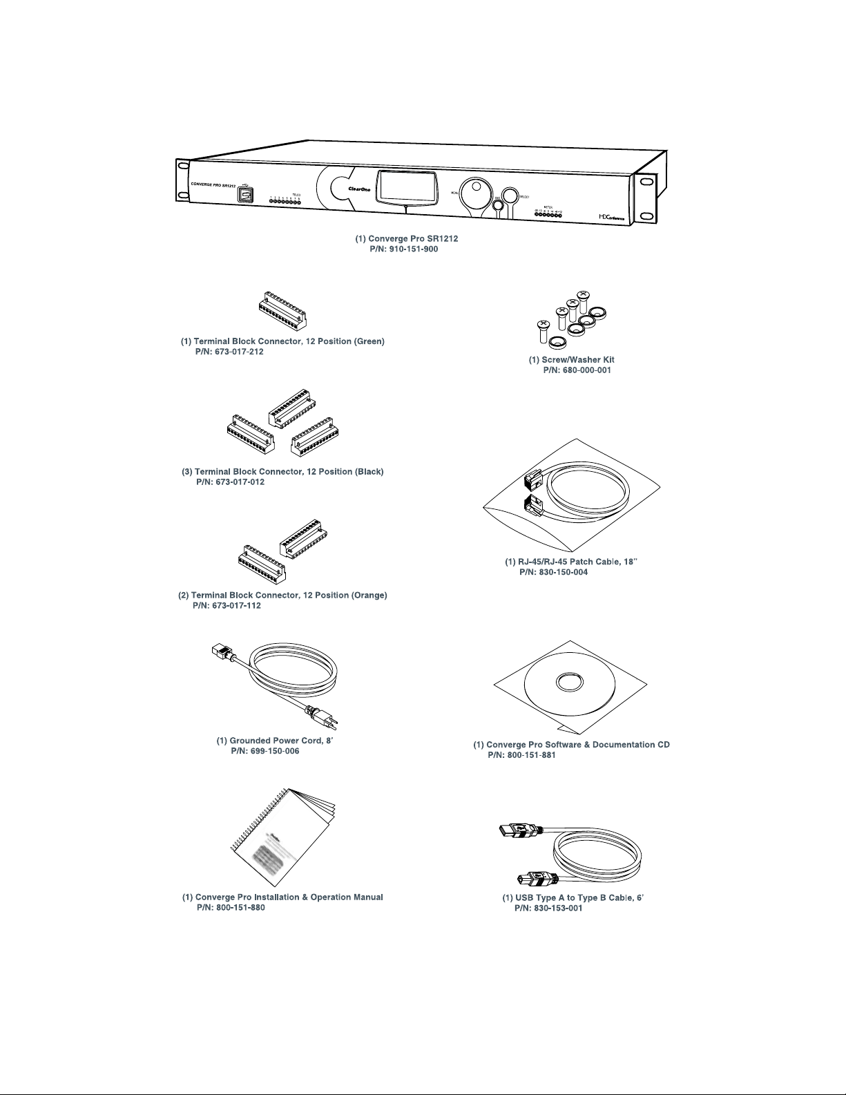
Converge Pro SR1212 Package Contents
21
Page 27
Converge Pro SR1212A Package Contents
CABLE ASSEMBLY, RJ45/RJ45 18"
830-150-004 (QTY 1)
MANUAL, CONVERGE 840T
800-151-880 (QTY 1)
CABLE ASSY, USB A-B TYPE 6FT
830-153-001 (QTY 1)
PWR CORD, MOLDED 6' BLK 3 COND
699-150-006 (QTY
1)
CONN, TERM BLOCK/F 12 POS BLACK
673-017-012 (QTY 2)
CONN, TERM BLOCK/F 12 POS ORANGE
673-017-112 (QTY 2)
CONN, TERM BLOCK/F 12 POS GREEN
673-017-212 (QTY 1)
CD, CONVERGE PRO PRODUCT FAMILY
800-151-881 (QTY 1)
SCREW/WASHER ACC KIT, RACK DECOR 4EA BLK
680-000-001 (QTY 1)
Converge SR 1212A Packing Contents
CONVERGE SR 1212A (QTY 1)
22
Page 28
CONTROLS AND CONNECTIONS
SELECTMENU
ESC
-30 -10 -4 0+4+8+12
METER
12345678
CONVERGE PRO 880
ClearOne
Converge 880
11 : CONVERGE880-77
1.0.00
IPA: 192.168.1.1
ACBDEF G
SELECTMENU
ESC
1 2 3 4 5 6 7 8
A B C D E F
H
I
G
SELECTMENU
ESC
TELCO ON / OFF
-30 -10 -4 0+4+8+12
METER
1234 TX RX
TELCO
CONVERGE PRO 840T
ClearOne
Converge 840T
32: CONVERGE840T-F0
1.0.00
IPA: 192.168.1.2
ACBDEF G
H I
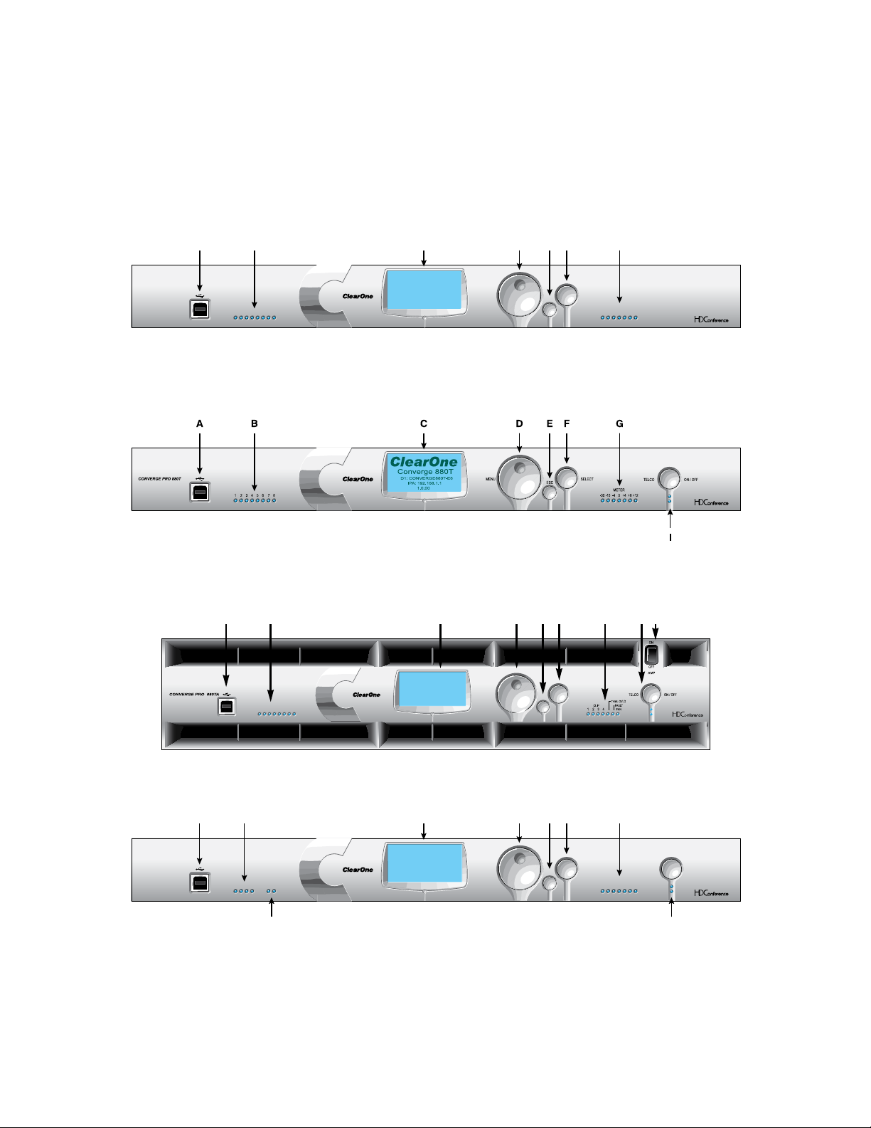
Refer to the following diagrams and descriptions for Converge Pro front panel controls and back panel connectors.
Converge Pro Front Panels
Converge Pro 880 Front Panel
Converge Pro 880T Front Panel
Converge Pro 880TA Front Panel
Converge Pro 840T Front Panel
23
Page 29
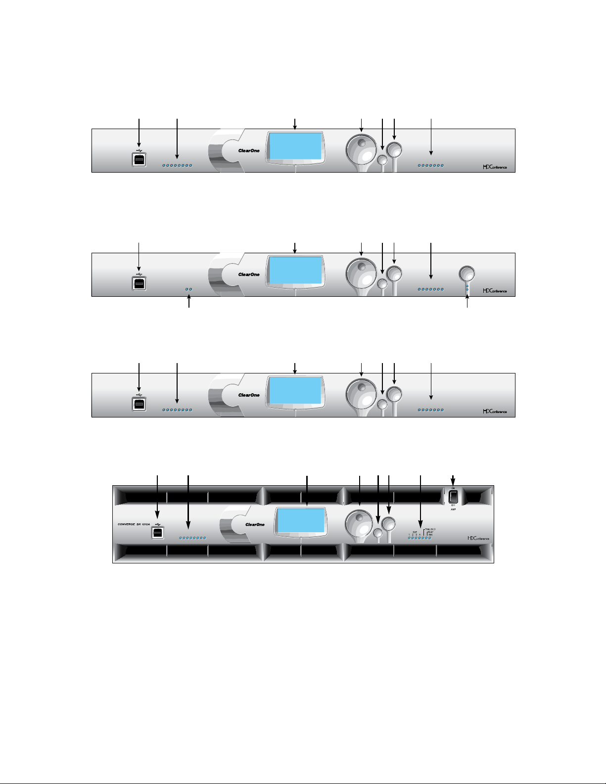
Converge Pro 8i Front Panel
SELECTMENU
ESC
-30 -10 -4 0+4+8 +12
METER
12345678
CONVERGE PRO 8i
ClearOne
Converge 8i
A6: CONVERGE8i-1C
1.0.00
IPA: 192.168.1.4
ACBDEF G
SELECTMENU
ESC
TELCO ON / OFF
-30 -10 -4 0+4+8+12
METER
TX RX
TELCO
CONVERGE PRO TH20
ClearOne
Converge TH20
2F: CONVERGETH20-3A
1.0.00
IPA: 192.168.1.3
ACDEFG
H I
SELECTMENU
ESC
-30 -10 -4 0+4+8 +12
METER
12345678
CONVERGE PRO SR1212
ClearOne
Converge SR1212
G7: CONVERGE880-6F
1.0.00
IPA: 192.168.1.1
ACBDEF G
SELECTMENU
ESC
1 2 3 4 5 6 7 8
A B C D E F G H
Converge Pro TH20 Front Panel
Converge Pro SR1212 Front Panel
Converge Pro SR1212A Front Panel
Converge Pro Front Panel Control Descriptions
USB Type B PortA. : Provides convenient front panel connectivity for laptops and PCs.
Microphone-On LEDsB. : Indicate microphone gate status and mute state.
LCD DisplayC. : Shows model number, unit name, IP address, firmware version, menu pages, menu options,
configuration settings, and parameter values.
Menu DialD. : Navigates the Converge Pro LCD programming menu and enables you to modify basic
configuration settings.
ESC ButtonE. : Returns you to the previous screen on the LCD display.
Select ButtonF. : Displays the Converge Pro LCD programming menu and selects the highlighted option.
24
Page 30

LED Bar MeterG. : Displays the audio level of a selected input, output, processing, or fader channel. Default
meters: 880-Output 12, 880T-Output 12 , 840T-Output 8, 8i-Mic 1, TH20-Telco Tx, SR1212-Output 12.
AMP Fault Indicator• LEDs(880TA, SR 1212A): Indicates amplifier faults:
1-4 indicates clip »
5 indicates thermal overload »
6 indicates fault »
7 indicates fan on/off »
Amplifier On/Off SwitchH. (880TA, SR 1212A): Turns power to the amplifiers on or off.
NOTE (880TA, SR 1212A): This does NOT disconnect power from the AC mains. To disconnect unit
power from the mains, disconnect the unit’s power cord from the mains socket. To reconnect power, plug
the unit’s power cord into the mains socket following all safety instructions and guidelines.
Telco On/Off Button & LEDsI. : The button connects/disconnects the telephone line attached to the device
and the LEDs indicate the connection status of the attached telephone line (840T, TH20, 880T, 880TA).
25
Page 31

Converge Pro Rear Panels
VOLTAGE RANGE 100-240 VAC 2A
FREQUENCY 50Hz / 60Hz
MIC / LINE
1234 1234
LINE IN
LINE OUT
9101112
LINE OUT
9101112
5678 5678
+-
LINK IN
LINK OUT
RS-232
CONTROL / STATUS
A
B
PC
LAN
123457896
LINE IN
LINE OUT
5 6 7 8
1
10
11
2 3 4
6
7
8
9
1 2 3 4 1 2 3 4
5 6 7 8
5 6 7 8
,
R
12
VOLTAGE RANGE 100-240 VAC 2A
FREQUENCY 50Hz / 60Hz
MIC / LINE
1234 1234
LINE INLINE OUT LINE OUT
5678 5678
+-
LINK IN
LINK OUT
RS-232
CONTROL / STATUS
A
B
PC
LAN
TELCO
LINE
SET
123457896
10
11
VOLTAGE RANGE 100-240 VAC 2A
FREQUENCY 50Hz / 60Hz
MIC / LINE
1234
LINE IN
9101112
5678
+-
LINK IN
LINK OUT
RS-232
CONTROL / STATUS
A
B
PC
LAN
1247896
Converge Pro 880 Rear Panel
Converge Pro 880T Rear Panel
Converge Pro 880TA Rear Panel
Converge Pro 840T Rear Panel
Converge Pro 8i Rear Panel
26
Page 32

Converge Pro TH20 Rear Panel
VOLTAGE RANGE 100-240 VAC 2A
FREQUENCY 50Hz / 60Hz
12 12
LINE IN LINE OUT
LINK IN
LINK OUT
RS-232
CONTROL / STATUS
A
B
PC
LAN
TELCO
LINE
SET
1457896
11
VOLTAGE RANGE 100-240 VAC 2A
FREQUENCY 50Hz / 60Hz
MIC / LINE
12341234
LINE IN
LINE OUT
9101112
LINE OUT
9101112
56785678
+-
LINK IN
LINK OUT
RS-232
CONTROL / STATUS
A
B
PC
LAN
123457896
1110
LINE IN
LINE OUT
5 6 7 8
1
10
12
2 3 4 6
7
8
1 2 3 4 1 2 3 4
5 6 7 8
5 6 7 8
9
,
R
Converge Pro SR1212 Rear Panel
Converge Pro SR1212A Rear Panel
Converge Pro Rear Panel Connectors
AC Power1. : IEC connector, 100 – 240VAC auto-adjusting, 50/60Hz.
Warning: This equipment must be connected to an AC mains socket outlet with a protective earthing
connection. The third prong of this connector (ground) is an important safety feature. Do not attempt to
disable this ground connection by using an adaptor or other method.
Mic/Line Inputs2. : Mini-terminal push-on block connector for any combination of microphone and/or line level
inputs. (Converge Pro 880: 8 inputs. Converge Pro 880T: 8 inputs. ConvergePro 880TA: 8 inputs. Converge
Pro 840T: 4 inputs. Converge Pro 8i: 8 inputs. Converge Pro TH20: 0 inputs. Converge SR 1212: 8 inputs.
Converge SR 1212A: 8 inputs.)
Line Outputs3. : Mini-terminal push-on connector for line-level outputs (880, 880T, 880TA, 840T, SR 1212, SR
1212A).
Line Inputs4. : Mini-terminal push-on block connector for line level inputs only. (Converge Pro 880: 4 inputs.
Converge Pro 880T: 4 inputs. Converge Pro 880TA: 4 inputs. Converge Pro 840T: 4 inputs. Converge Pro 8i: 4
inputs. Converge Pro TH20: 2 inputs. Converge SR 1212: 4 inputs. Converge SR 1212A: 4 inputs.)
Line Outputs5. : Mini-terminal push-on block connector for line-level outputs (880, 880T, 840T, TH20, SR1212).
27
Page 33

Link In and Link Out Ports6. : Two RJ-45 E-bus (expansion bus) connectors used to connect
multiple Converge Pro units together to create a site. You can connect up to twelve Converge Pro
840T/880/880T/880TA/8i/SR 1212/SR 1212A units, up to 16 Converge Pro TH20 units, or any combination
thereof, where the total number of microphone inputs does not exceed 96. Maximum cable length is 200 feet
using Category 5 unshielded twisted pair cable.
WARNING: Use the Link In and Link Out ports with Converge Pro Devices ONLY. Connecting
ANY other devices to the Link In and Link Out ports, including ClearOne XAP or PSR1212
products, or Power Over Ethernet (PoE) devices, will result in severe equipment damage.
RS-232 Serial Port7. : Female DB9 connector for connecting to a laptop, computer, or remote control serial
devices (such as AMX and Crestron controllers).
NOTE: Converge Console software cannot connect via the RS-232 port; use USB or Ethernet.
Control/Status A and B Ports8. : Two female DB25 connectors used for GPIO interactions between Converge
Pro devices and external control devices (such as wall switches and push-to-talk microphones). This enables
external devices and controller software to access the Converge Pro command set, including common
functions such as volume control, muting, room combining, and preset changes.
PC and LAN Ethernet Ports9. : Two RJ-45 10/100Mbps auto-sensing Ethernet ports. The LAN port connects
Converge Pro devices to a network. The PC port provides a pass-through network connection for use with a
standard (not crossover) patch cable. The LEDs adjacent to each port indicate connection status and packet
traffic activity.
Speaker Posts (880T, 840T)/Amplifier Terminal Block (880TA, SR1212A)10. :
880T,840T--Twopost/bananaplugconnectorsusedtoconnectanexternalspeaker(4Ω–16Ω).•
Internal power amplifiers eliminate the need for an external power amplifier.
880TA,SR1212A--8speakerterminalsusedtoconnectanexternalspeaker(8Ω).Four,35Watt•
internal power amplifiers eliminate the need for an external power amplifier.
NOTE: To reduce risk of electrical shock and damage to equipment, never connect wiring or
external equipment while the amplifier is power is on. Class 2 wiring is required. Maintain
the correct polarity (+/-) on output connectors. (For example: Channel 1 positive (+)
speaker lead connects to amplifier’s channel 1 positive terminal. Channel 1 negative (-)
speaker lead connects to amplifier’s channel 1 negative terminal. Repeat this procedure
for each channel.
28
Page 34

Telco Line and Telco Set Ports11. : Two RJ-11 connectors telephone ports. The Telco Line port connects an
analog telephone line to Converge Pro devices. The Telco Set port provides a pass-through connection for
telephone handsets (880TA, 880T, 840T, TH20).
NOTE: The Telco Set port is not available for use when the telephone hybrid is off-hook.
Amplifier Terminal Block (880TA, SR 1212A)12. : 12 speaker terminals used to connect an external speaker
(70/100 v). Four, 35 Watt internal power amplifiers eliminate the need for an external power amplifier.
NOTE: To reduce risk of electrical shock and damage to equipment, never connect wiring
or external equipment while the amplifier is power is on. Class 2 wiring is required.
Maintain the correct polarity on output connectors. (For example: Channel 1 70/100V
speaker lead connects to amplifier’s channel 1 70V or 100V terminals. Channel 1 GND
(or Common) speaker lead connects to amplifier’s channel 1 GND terminal. Repeat
this procedure for each channel.
29
Page 35

CHAPTER 2: EXPANSION BUS & LCD PROGRAMMING
VOLTAGE RANGE 100-240 VAC 2A
FREQUENCY 50Hz / 60Hz
MIC / LINE
1234
LINE IN
9101112
5678
+-
LINK IN
LINK OUT
RS-232
CONTROL / STATUS
A
B
PC
LAN
VOLTAGE RANGE 100-240 VAC 2A
FREQUENCY 50Hz / 60Hz
MIC / LINE
12341234
LINE INLINE OUT LINE OUT
5678 5678
+
-
LINK IN
LINK OUT
RS-232
CONTROL / STATUS
A
B
PC
LAN
TELCO
LINE
SET
VOLTAGE RANGE 100-240 VAC 2A
FREQUENCY 50Hz / 60Hz
MIC / LINE
12341234
LINE IN
LINE OUT
9101112
LINE OUT
9101112
56785678
+
-
LINK IN
LINK OUT
RS-232
CONTROL / STATUS
A
B
PC
LAN
VOLTAGE RANGE 100-240 VAC 2A
FREQUENCY 50Hz / 60Hz
12 12
LINE IN LINE OUT
LINK IN
LINK OUT
RS-232
CONTROL / STATUS
A
B
PC
LAN
TELCO
LINE
SET
Converge Pro 840T
Link Out
Link In
Link Out
Link Out
Link In
Link In
Converge Pro TH20Converge Pro 8i
Converge Pro 880
VOLTAGE RANGE 100-240 VAC 2A
FREQUENCY 50Hz / 60Hz
MIC / LINE
1234
LINE IN
9101112
5678
+-
LINK IN
LINK OUT
RS-232
CONTROL / STATUS
A
B
PC
LAN
VOLTAGE RANGE 100-240 VAC 2A
FREQUENCY 50Hz / 60Hz
MIC / LINE
12341234
LINE INLINE OUT LINE OUT
5678 5678
+
-
LINK IN
LINK OUT
RS-232
CONTROL / STATUS
A
B
PC
LAN
TELCO
LINE
SET
VOLTAGE RANGE 100-240 VAC 2A
FREQUENCY 50Hz / 60Hz
MIC / LINE
12341234
LINE IN
LINE OUT
9101112
LINE OUT
9101112
56785678
+
-
LINK IN
LINK OUT
RS-232
CONTROL / STATUS
A
B
PC
LAN
VOLTAGE RANGE 100-240 VAC 2A
FREQUENCY 50Hz / 60Hz
12 12
LINE IN LINE OUT
LINK IN
LINK OUT
RS-232
CONTROL / STATUS
A
B
PC
LAN
TELCO
LINE
SET
Converge Pro 840T
Link Out
Link In
Link Out
Link Out
Link In
Link In
Converge Pro TH20Converge Pro 8i
Converge Pro 880
EXPANSION BUS
The Expansion Bus (E-bus) allows you to connect multiple Converge/Converge-Pro units together to create powerful
audio and conferencing solutions for any size venue. The E-bus is a proprietary digital audio bus that provides
control and audio data links between devices.
Expansion Bus Connections
Using the E-bus Link In and Link Out ports, you can connect up to 34 Converge Pro 880/880T/880TA/840T/8i and
Converge SR 1212/SR 1212A units, and up to 16 Converge Pro TH20 units, where the total number of microphone
inputs does not exceed 96.
Connect units in daisy-chain fashion (as shown below) using the 18” straight-through patch cable included with
each unit (Part # 830-150-004) . For larger distances between units, use CAT 5 twisted pair cable with RJ-45
connectors. The maximum cable length between connected units is 200 feet (61 meters).
Audio and Control Buses
The E-bus allows audio routing between source devices and destination devices on the E-bus network. The E-bus
contains 18 independent digital audio buses labeled I–Z, which can route mic or line inputs in any combination
across the E-bus network. The E-bus also contains eight PA adapt/acoustic echo cancellation reference buses, six
global gating buses, and one control bus.
S-Z Buses: These eight buses are line input mixer buses. They are used to route auxiliary audio, such as from a CD
player or VCR, to and from other units on the network. These buses are also used as mic mixer buses when NOM
count is not required.
I-R Buses: These ten audio buses are generally used for routing microphone audio between Converge/Converge
Pro devices. Information about the number of gated microphones (NOMcount) and other relevant information for the
microphone mixers are tracked for microphones routed to these buses. By default, all microphones are routed to
the O bus.
PA Adapt/Acoustic Echo Cancellation Reference Buses: These buses allow an input from a Converge/
Converge Pro device to reference an output on another linked device for AEC and PA Adaption. See AEC Reference/
PA Adapt Reference and AEC for more information.
Global Gating Groups A-F: These buses are microphone gating groups that support first-mic priority, maximum
number of mics, etc. and work across all linked Converge/Converge Pro devices. Unlike the audio buses, they
contain only mic status and gate parameters. See the Gating and Gating Group topics for more information.
Control Bus: The control bus is an independent channel from the E-bus’s audio channel. This allows control
information to pass even if the units are not using the audio link. All models support the use of the Converge/
Converge Pro serial command set through the control bus.
30
Page 36

DEVICE IDS
CONVERGE MENU
Channels
Settings
PresetsMacros
SETTINGS PA GE 1/2
RS232
Network
DefaultDID
Device IDs provide unique identifiers for all Converge/Converge Pro units that are linked together. After making
E-bus connections between units, you must set a unique Device ID number for all units of the same Device Type in
the network.
Device Types and IDs
Device Types and Device IDs by model are as follows:
Model Device Type Device ID Range
880 1 0-B
TH20 2 0-F
840T 3 0-B
8i A 0-B
880T D 0-B
880TA H 0-B
SR 1212 G 0-B
SR 1212A I 0-B
NOTE: All models ship from the factory with a default DID of 0.
Assigning Device IDs
Use the following procedure to assign device IDs using the front panel controls:
Press the 1. Select button on the front panel. The Converge Menu appears.
Use the 2. Menu Dial to highlight the Settings menu. Press the Select button. The Settings menu appears.
Use the 3. Menu Dial to highlight DID. Press the Select button. The Device ID menu appears.
31
Page 37

DEVICE ID MENU
4
2
3
1
0
5
6
Use the 4. Menu Dial to highlight the desired value. Press the Select button to select it.
CHANGING DID MENU
Change DID to
4?
No
Ye s
SELECTMENU
ESC
1 2 3 4 5 6 7 8
A B C D E F
H
I
G
The 5. Change DID Menu prompt appears. Choose Yes to set the selected DID value, or No to return to the
Device ID menu.
Press 6. Esc until to return to the Settings menu.
Repeat this process for each device on the E-bus network.7.
NOTE: You can also set Device IDs in the Unit Properties screen in Console (when
disconnected). However, DID assignments made in Console must match the DID
assignments made using the front panel.
LCD PROGRAMMING OVERVIEW
LCD Programming allows you to make simple configuration adjustments using front panel controls (shown below).
USB Type B PortA. : Provides convenient front panel connectivity for laptops, computers, and other USB
devices.
Microphone-On LEDsB. : These LEDs indicate microphone gate and mute status.
LCD DisplayC. : Shows model number, unit name, IP address, programming menu pages, menu options,
configuration settings, and parameter values.
Menu DialD. : Navigates the LCD programming menu and enables you to select/modify configuration settings.
ESC ButtonE. : Returns you to the previous screen on the LCD display.
32
Page 38

Select ButtonF. : Displays the LCD programming menu and selects the highlighted option.
CONVERGE MENU
Channels
Settings
PresetsMacros
Channels
Mics
Inputs
Outputs
Process
Faders
Telco Tx
Telco Rx
Pwr Amp
Settings
RS-232
Network
DID
Default
Contrast
Macros
Macros
1-255
Presets
Presets
1-32
ClearOne
Converge 840T
32: CONVERGE840T-F0
1.0.00
IPA: 192.168.1.2
LED Bar MeterG. : Displays the audio level of a selected input, output, processing, or fader channel. Default
meters: 880-Output 12, 880T-Output 12 , 840T-Output 8, 8i-Mic 1, TH20-Telco Tx, SR1212-Output 12.
AMP Fault Indicator• (880TA, SR 1212A): Indicates amplifier faults.
Telco Tx (transmit)/Telco Rx (receive) LEDsH. : Display transmit, receive, and mute status of the connected
telephone line.
Telco On/Off Button & LEDsI. : The button connects/disconnects the telephone line attached to the device;
the LEDs indicate the connection status of the line.
Amplifier On/Off SwitchJ. (880TA, SR 1212A): Turns power to the unit on or off.
In addition to making configuration adjustments from the front panel, you can also run macros and execute presets.
For more information on using front panel controls, see Controls and Connections.
Adjusting LCD Menu Parameters
Use the following procedure to adjust LCD Menu parameters:
Press the 1. Select button to access the Converge Menu.
Scroll to the parameter you want to adjust using the 2. Menu Dial.
Press the 3. Select button to select the parameter. The parameter will stop flashing when selected.
Select the value for the parameter using the 4. Menu Dial.
Press the 5. Select button to save the parameter value. To discard the change and return to the previous menu,
press the Esc button.
NOTE: Use the Console software in Configuration Mode for advanced configuration tasks.
LCD Menu Tree
33
Page 39

As shown above, the main menus on the LCD display are:
Channels•
Settings•
Macros•
Presets•
34
Page 40

LCD Default Display
Model
DeviceType, ID, Name
Firmware Level
IP Address
ClearOne
Converge 840T
32: CONVERGE840T-F0
1.0.00
IPA: 192.168.1.2
CONVERGE MENU
Channels
Settings
PresetsMacros
When you power up a Converge/Converge Pro unit, the LCD display reads Initializing. If an error occurs, contact
ClearOne Technical Support. When initialization is complete, ClearOne Converge[Model Number] appears on
the LCD panel, along with the device type, device ID, device name, IP address, and firmware revision level as shown
below.
To access the LCD menu, press the Select button. The Converge Menu appears as shown below.
Front Panel Lock
Using Console, you can create a PIN code and lock the front panel to prevent unauthorized access to LCD menu
functions. When the lock feature is enabled and the front panel is unlocked, it will automatically re-lock after 3
minutes of inactivity. See the Unit Properties topic for instructions on how to enable the lock feature.
For more information, see the Table of Contents for these related topics:
Macros•
Presets•
Controls and Connections•
Console Configuration Mode•
Mic Input Settings•
Line Input Settings•
Telco RX Settings•
Telco TX Settings •
Processing Settings•
Output Settings•
LCD Channels Menu•
LCD Settings Menu•
LCD Macros Menu•
LCD Presets Menu•
Device IDs•
Unit Properties•
35
Page 41

LCD CHANNELS MENU
CHANNELS PAGE 1/2
Mics
Inputs
ProcessOutputs
Meter
Gain
dB Mute Off
1-Input 1
dB
-50
+0
The LCD Channels Menu allows you to adjust the gain level and turn mute on or off for all channels.
Accessing the Channels Menu
To access the Channels menu, press the Select button on the front panel, use the Menu Dial to select
Channels, and press the Select button.
The Channels menu appears as shown below:
Channels menu options (i.e. channel types) include:
Mics•
Inputs•
Outputs•
Process•
Faders•
Telco Tx •
Telco Rx•
Pwr Amp •
After you select an option, a list of all available channels of that type is displayed. Use the Menu Dial to select the
channel you want to configure and press the Select button. The Channels display appears.
Channel Display
The channel display is identical for every channel type, with the exception of the channel ID and channel label, which
both vary depending on the channel selected.
As shown below, the display includes a peak-level meter, a peak dB reading, a gain level adjustment box, and a
mute selector.
Setting Channel Gain and Mute
The procedure for setting gain and mute is the same for all channel types:
Use the 1. Menu Dial to highlight Gain or Mute
36
Page 42

Press the 2. Select button
SETTINGS PA GE 1/2
RS232
Network
DefaultDID
Select the desired value using the 3. Menu Dial
Press the 4. Select button to set the selected value
Press the 5. Esc button to return to the Channels menu
NOTE: When mute is set to on for a mic input channel, the Microphone-On LED for that channel
illuminates red on the front panel.
For more information, see the Table of Contents for these related topics:
LCD Programming Overview•
LCD Channels Menu•
LCD Settings Menu•
LCD Macros Menu•
LCD Presets Menu•
Controls and Connections•
Mic Input Settings•
Line Input Settings•
Output Settings•
Process Settings•
Fader Settings•
Telco Tx Settings •
Telco Rx Settings •
Pwr Amp•
LCD SETTINGS MENU
The LCD Settings Menu allows you to configure serial port settings and Device IDs, view network IP settings,
change the LCD contrast level, and restore factory default settings for a unit.
Accessing the Settings Menu
To access the Settings menu, press the Select button on the front panel, use the Menu Dial to select Settings,
and press the Select button.
The Settings menu appears as shown below:
Settings menu options include:
RS-232•
Network•
DID•
Default•
Contrast•
37
Page 43

These options are described in the following sections.
RS-232
There are two parameters in the RS-232 menu: Baud Rate and Flow Control. To change these settings, use the
following procedure:
Use the 1. Menu Dial to highlight Baud Rate or Flow Control
Press the 2. Select button
Select the desired value using the 3. Menu Dial
Press the 4. Select button to set the selected value
Press the 5. Esc button to return to the Settings menu
You can also use the Comm tab of the Unit Properties screen to change these settings.
Baud Rate
This parameter allows you to set the baud rate to 9.6kbps, 19.2kbps, 38.4kbps, 57.6kbps, or 115.2kbps. The default
is 57.6 kbps. Select the baud rate you want to use, then press the Select button. A message appears on the LCD
display indicating the change is in progress, and another indicating the change is complete. When finished, the
display returns to the RS-232 sub-menu.
Flow Control (Hardware)
All models use the RTS and CTS pins on the RS-232 port to regulate the transmission and reception of data. You
can enable or disable flow control on the front panel, and set the flow control type in the Unit Properties window in
Console.
If you select On (default) from the front panel LCD menu, select Hardware as the flow control type in the Unit
Properties window. If you disable flow control on the front panel, select None in the Unit Properties window.
When None is selected, the unit ignores flow control, and the relies on the connected external control device to
ensure data is not lost.
NOTE: ClearOne recommends that you leave Flow Control enabled and connect all DB9 pins to
avoid communication errors.
Network
The Network submenu displays the unit name, IP address, Gateway, and Subnet Mask settings for the unit. You
cannot change any of these settings from the Network submenu. Use the Unit Properties screen in Console to
change these settings.
DID
The DID submenu allows you to select a Device ID for the unit. Select the DID you want to use, press the Select
button. Answer Yes to the prompt to change the DID, or No to keep the existing setting.
You can also use the General tab of the Unit Properties screen in Console to change this setting when disconnected
from the unit. However, DID assignments made in Console must match DID assignments made using the front
panel.
Default
Default restores ALL settings to their factory default values. Answer Yes to the prompt to restore default settings, or
No to retain the existing settings.
Contrast
Contrast allows you to change the LCD contrast level. Use the Menu Dial to adjust the contrast level, then press
the Select button to save it.
38
Page 44

For more information, see the Table of Contents for these related topics:
MACRO MENU
1-Gain Adjust 7-8
2-UnProgrammed
3-UnProgrammed
4-UnProgrammed
5-UnProgrammed
6-UnProgrammed
7-UnProgrammed
LCD Programming Overview•
LCD Channels Menu•
LCD Macros Menu•
LCD Presets Menu•
Site Properties•
String Tab•
Unit Properties•
LCD MACROS MENU
The LCD Macros Menu allows you to run macros from the front panel. To record Macros, use the Macro Tab in
Console.
Accessing the Macros Menu
To access the Macros menu, press the Select Button on the front panel, use the Menu Dial to select Macros, and
press the Select Button.
The Macro Menu appears as shown below:
Executing Macros
Use the following procedure to run macros from the front panel LCD display:
You can also run macros using the Macro tab or the Services menu in Console.
For more information, see the Table of Contents for these related topics:
Use the 1. Menu Dial to highlight the macro you want to run
Press the 2. Select button
Answer 3. Yes at the prompt that appears to run the selected macro, or No to cancel.
Press the 4. Esc button to return to the main LCD menu.
LCD Programming Overview•
LCD Settings Menu•
LCD Channels Menu•
LCD Presets Menu•
Macro Tab•
39
Page 45

LCD PRESET MENU
PRESET MENU
1-Combine Room
2-UnProgrammed
3-UnProgrammed
4-UnProgrammed
5-UnProgrammed
6-UnProgrammed
7-UnProgrammed
The LCD Preset Menu allows you to execute presets from the Converge Pro front panel. To create presets, use
Console in Preset Mode.
Accessing the Presets Menu
To access the menu, press the Select button on the front panel, use the Menu Dial to select Presets, and press
the Select Button.
The Preset Menu appears as shown below:
Executing Presets
Use the following procedure to execute presets from the front panel LCD display:
Use the 1. Menu Dial to highlight the preset you want to execute
Press the 2. Select button
Answer 3. Yes at the prompt that appears to run the selected preset, or No to cancel
Press the 4. Esc button to return to the main LCD menu
You can also run presets from the Services menu while Console is in Configuration Mode.
For additional information, refer to the Table of Contents for these related topics:
LCD Programming Overview•
LCD Settings Menu•
LCD Channels Menu•
Preset Mode•
Console Overview•
Services Menu Overview•
Configuration Mode Overview•
40
Page 46

CHAPTER 3: CONVERGE CONSOLE PROGRAMMING
INSTALLING CONVERGE CONSOLE
The Converge Console software is designed for Windows XP and Vista operating systems.
Ensure that all other programs or applications are closed and disconnect any USB cables from all Converge/1.
Converge Pro devices (you will reconnect them later).
Insert the 2. Converge/Converge Pro Installation & Documentation CD into the CD or DVD-ROM drive.
If the Autorun feature is enabled on the PC, the Converge/Converge Pro Installation window opens 3.
automatically. Click the Converge Console Software menu option on the left side of the screen to begin
installation.
If Autorun is not enabled, open » My Computer navigate to the drive holding the Converge/Converge Pro
Installation & Documentation CD. Double-click on the drive icon and launch setup.exe.
When the 4. Converge/Converge Pro Installation & Documentation CD window appears, click the
Converge Console Software menu option on the left side of the screen.
The setup program begins by installing Visual C++ runtime libraries. If prompted, click the 5. Install button
(shown below).
When the libraries complete installation, Setup checks the system for Adobe Flash. If Adobe Flash is not 8.
installed, Setup starts the Flash installation with a dialog (shown below).
Press 9. Yes to install Adobe Flash. Once Flash installs, you will need to repeat this installation procedure
starting at step 6 to complete Console installation.
NOTE: Adobe Flash is required to use Console. Clicking No will abort the Flash and Console.
The 10. Converge Console Setup Wizard appears. Press the Next button and navigate through the License
Agreement and Information screens that appear.
At the 11. Select Installation Folder window, choose the directory where you want to install Console. Press the
Disk Cost button to analyze available and required free space (if needed).
NOTE: ClearOne recommends that you use the default directory when installing Console.
Press the 12. Next button until installation starts.
A Windows unsigned driver warning dialog appears as shown below. Click 13. Continue Anyway (Windows
XP) or Install this driver software anyway (Windows Vista) to proceed copy Converge/Converge Pro USB
drivers onto your system.
41
Page 47

NOTE: If you click STOP Installation (Windows XP) or Don’t install this driver software
(Windows Vista), Windows will terminate USB device driver installation. Console installation
will continue to completion, and Console will function properly over IP. However, you will
not be able to use Console over USB.
Follow the instructions that appear on-screen to complete installation. 14.
When Console installation is complete, the Converge Console 15.
can now start Console over IP by double-clicking the icon, or through the All Programs > ClearOne
Communications > Converge Console program group in the Windows Start menu.
To use a USB connection with Console, connect USB cables between the PC and the Converge/Converge 16.
Pro device.
NOTE: Windows automatically detects the device and begins the USB device driver installation.
This process occurs the first time a new Converge/Converge Pro model is connected to
the system, and once when you switch to a different USB port on the system. If you install
drivers for a model and subsequently connect another model to the system via USB,
Windows will repeat the installation process for the new device type.
When the 17. Found New Hardware Wizard appears, select the No, not this time radio button. Click Next to
begin installation.
icon appears on your desktop. You
42
Page 48

Select the 18. Install the software automatically radio button in the second screen of the wizard (shown
below), then click Next to proceed with installation.
When the Windows unsigned driver warning dialog appears, click 19. Continue Anyway (Windows XP) or
Install this driver software anyway (Windows Vista) to install the drivers.
When the USB driver installation is complete, click 20. Finish to close the wizard.
If you will be using IP to run Console, connect Ethernet cables between your LAN and Converge/Converge 21.
Pro device(s).
The Console software and your Converge/Converge device(s) are now ready for use. If you experience any
problems during installation, contact ClearOne technical support.
43
Page 49

CONVERGE CONSOLE OVERVIEW
The Converge Console software provides a powerful, intuitive interface for configuring and controlling your
Converge/Converge Pro system. While you can use LCD Programming for simple configuration tasks, you must use
Console to configure the advanced settings required to customize units for your application.
Accessing Converge Console
Start Converge Console by double-clicking the desktop icon, or by clicking the Start button in Windows and
selecting All Programs > ClearOne Communications > Converge Console > Converge Console from the
program list.
After Console loads, you can open an existing Site File from the File menu, or create a new site file by selecting
New Site. When a site file is opened, Console displays the Unit Tab as shown below.
Default User ID and Password
Connecting to a site with Console requires a user name and password. The default user name is clearone; the
default password is converge.
NOTE: User names and passwords are not case sensitive. ClearOne recommends that you
record user names and passwords and store them in a secure place. There is no way
to retrieve passwords. If you forget a password, the only way to connect to the device
is to Default the unit.
After connecting, you can add/modify user IDs, change passwords, and set access privileges using the Site
Properties dialog.
Navigating Converge Console
The Console window consists of the components described in the following sections.
44
Page 50

Menu Bar
Menus available on the Menu Bar include:
File•
View•
Add•
Connect•
Modes•
Services•
Help• : Opens the context-sensitive help system; provides software and firmware version information.
Button Bar
Controls on the Button Bar include:
Open Site
Save Site
Connect
Disconnect
Configuration Mode
Preset Mode
Execute Preset
Run Macro
Dialer
Phonebook
Label Editor
Device Log
Debug Console
Web Builder
Firmware Loader
Create Site
Event Log
Safety Mute: Toggles Safety Mute on and off. Safety Mute holds all outputs in a muted state.
Signal Generator LED: Flashes green when the signal generator for any unit in the site is turned on.
Help: Opens the context-sensitive help system; provides software and firmware version information.
45
Page 51

Tab Bar
Tabs available on the Tab Bar include:
Unit•
Channel•
Matrix•
AEC Reference (PA Adapt Reference for SR 1212/SR 1212A)•
Macro•
Gating•
Control•
String•
Event Scheduler•
Database•
Clicking a tab displays the screen for that tab in the Console Center Pane.
Site Pane
In Configuration Mode, the Site Pane contains the Site Selection drop-down list, Site View tab, and Tree View tab.
Right-clicking in either the Site View tab or the Tree View tab brings up a context menu with site, unit, channel, and
reporting options applicable to the selected unit type.
46
Page 52

In Preset Mode, the Site Pane displays the Current Site, Current Unit, Preset Selection list, and the Preset Name,
Description, and Preset Mask entry fields.
Center Pane
The Center Pane displays the screen for the selected Console Tab. As shown above, the default screen is Unit Tab.
47
Page 53

Objects Pane
The Object Pane contains the AV Devices tab, which allows you to select from a list of pre-configured device settings
and apply them instantly to a channel; and the Objects tab, which allows you to select from a list of custom channel
objects and instantly apply them to a specific channel type. AV Devices and channel Objects are stored in the
Database.
Status Bar
The Status Bar displays the current Console Mode, as well as connection status, site information, and unit
information.
The LEDs in the Status Bar indicate current status as follows:
Clear • (no LEDs illuminated): Not connected
Yellow: • Connecting/pending
Green: • Connected
Red: • Off-line
Purple: • Current with error
Console Modes
Console has two modes: Configuration Mode and Preset Mode. Configuration Mode allows you to configure a wide
range of advanced settings for your unit(s). Preset Mode allows you to create presets for specific venues and apply
them instantly to Converge/Converge Pro unit(s).
For additional information, refer to the Table of Contents for these related topics:
LCD Programming•
Site Properties•
Configuration Mode Overview•
Preset Mode Overview•
48
Page 54

SITE FILE OVERVIEW
Site Files allow you to store configuration settings for one or more units for a specific application or venue. Site
files also provide Console with the necessary information to communicate with the Converge/Converge Pro devices
using your PC.
Site files are a powerful tool for creating a library of configuration files for specific applications and room types. For
example, you can create a baseline site file for divided rooms that specifies mic gating, output crosspoints, AEC,
and AGC/ALC, store it on your hard drive, and use the file for other similar installations. This approach allows you to
standardize settings across venues.
NOTE: All units ship with a default site configuration file.
Site files also enable you to create users, set passwords, set unit master/slave control status, set up email
notification, and configure time/local parameters as described in the Site Properties topic.
Accessing Site Files
To open a Site file, select the File menu in Console.
49
Page 55

The File menu appears. Select Open Site as shown below.
The Open dialog appears as shown below.
Locate the site file you want to open and click Open. Console opens the site file, and it appears in the Site
Selection drop-down list in the Site Pane as shown below. Use the Files of type drop-down list to open G-ware
files (.PSR file extension) and convert them to convert G-ware site files to Converge site files.
The selected site file is now available for use. You can open up to four site files simultaneously and switch between
them using the Site Selection drop-down list.
50
Page 56

Saving Site Files
To save the current Site configuration parameters, including any changes made since the active Site file was
opened, click the Save button on the Button Bar, or select Save or Save As from the File menu.
For additional information, refer to the Table of Contents for these related topics:
Create A Site•
Connect to a Site•
Site Properties•
Console Overview•
Configuration Mode Overview•
Channel Tab Overview•
Matrix Tab•
51
Page 57

CONNECT TO A SITE
Connect To a Site
Click the Connect button on the Console Button Bar, or select Connect from the Connect Menu. The
Connect dialog appears as shown below.
Connection options include:
To automatically create a new site file, select the • Create New Document and Connect to Site radio button
To pull data from the unit to the current Site File, select the • Pull Data from Unit to Current Document radio
button (only available if a site file is open)
To push data from the current site file to the unit, select the • Connect to Site and Push Document radio
button (only available if a site file is open the unit is added)
To connect via USB, select the • USB Connection radio button
To connect via IP, select the • IP Connection radio button, and select a unit from the Available Addresses
drop-down list (or enter an IP address in the Enter Address entry box)
Press the Connect button to connect to the site or Cancel to close the dialog.
NOTE: The default login user name is ClearOne. The default password is Converge. User
names and passwords are not case sensitive.
Disconnect from a Site
To disconnect from a site, press the Disconnect button on the Console Button Bar, or select Disconnect from
the Connect menu. Answer Yes to the Confirm dialog that appears, or No to cancel.
52
Page 58
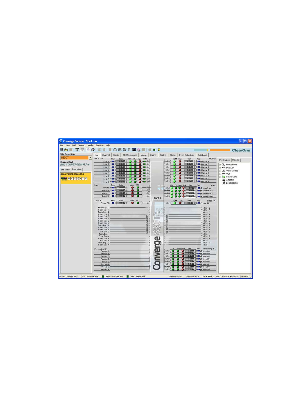
For additional information, refer to the Table of Contents for these related topics:
Site File Overview•
Site Properties•
Unit Communication (IP) Settings•
SITE PROPERTIES
Site Files are created and modified using the Site Properties window in Console. Site files contain all information
about a particular installation including properties for all units in a site. For more information, see the Site File
Overview topic.
Accessing Site Properties
To access the Site Properties window, select the File menu in Console, or right-click anywhere in the Site View or
Tree View panes and select Site Properties from the shortcut menu.
The File menu appears. Select Site Properties as shown below.
53
Page 59

The Site Properties window appears with the General tab selected.
Create A New Site
To create a new site, select New Site from the File menu or by clicking the New Site button on the Console
Button Bar. The Site Properties window appears.
NOTE: You must have administrator privileges to connect to units with Console, and to modify
user names and passwords. User names and passwords are not case sensitive.
Site Properties are described in the following sections.
Site Properties: General Tab
The General tab of the Site Properties window displays Site file information as shown above. Enter a site name, file
54
Page 60

author, and site description in the Site Info section of the tab. Press OK to save the changes, Cancel to close the
Site Properties window, or click on the Management or Time/Local tabs to continue site configuration.
Site Properties: Management Tab
The Management tab (shown below) enables you to configure SNMP parameters, email notification settings, as
well as user names and passwords.
Control Master Unit
All units in the site appear in the Control Master unit list. Selecting a Control Master unit designates that unit to
control the SNMP interactions for the entire site across IP-based networks. To use SNMP, the Control Master unit(s)
must be connected to the LAN via IP.
All other units in the site are Control Slave units. Control Slave units report events to the Control Master Unit for
SNMP reporting and SMTP email notifications.
Serial Control interactions and Audio Control interactions are not affected by a unit’s Control Master designation.
NOTE: All units are Control Slave units by default.
SNMP
In the SNMP section, enter the SNMP settings for the site. The Control Master nit uses this information to
communicate SNMP events, including events reported by Control Slave nits.
NOTE: The Installation & Documentation CD contains SNMP MIB files for each device type for
use with third-party SNMP management software.
Email Notifications
In the Email Notifications section, enter the SMTP Server address in the SMTP Server Address field and the IP
address of the server that will receive email notifications in the SMTP Server IP Address field. The recipient’s email
address in the Email Address field.
55
Page 61

User name/Passwords
In the User name/Passwords section, click the button for the user type that you want to create. The Name/
Password dialog appears as shown below.
NOTE: The default user name is clearone. The default password is converge. User names and
passwords are not case sensitive.
User access privilege levels are as follows:
Administrator• : Full Console and web portal access.
Manager• : Web access to Dialer, Maintenance, Registration, About, and Help pages.
User• : Web access to the Dialer, Registration, About, and Help pages.
Enter the appropriate user information and press OK to save the user information, or Cancel to return to the Site
Properties dialog.
Site Properties: Time/Local Tab
The Time/Local tab enables you to configure time settings and specify location information as shown below. As
shown below, you can set the date and time manually, synchronize the time with a PC, or use network time servers.
56
Page 62

In the Time section of the tab, select Local Time or Network Time for the clock synchronization source.
When Local Time is selected, the Apply button is activated; pressing it updates the date and time on all units in the
current site.
When Network Time is selected, you must enter the IP address(es) for the time synchronization server(s). The date
and time is updated for all units in the site when you press the OK button, and it is automatically synchronized with
the specified server(s).
Enter location information in the Location section of the tab (optional). Press OK to save the site file, or Cancel to
close the Site Properties window.
For additional information, refer to the Table of Contents for these related topics:
Site File Overview•
Connect To A Site•
Unit Properties•
Configuration Mode Overview•
57
Page 63

UNIT PROPERTIES
Unit Properties define properties for a specific Converge/Converge Pro unit. Unit Properties enable you to
configure general unit settings such as name, and telephone country code, as well as IP and serial communication
settings. Properties that apply to all units in a site are configured using Site Properties.
Accessing Unit Properties
To access the Unit Properties window, right click the unit you want to configure in either the Site View tab or the
Tree View tab of the Site Pane in Console.
The Site/Unit menu appears. Select Unit Properties as shown below.
The Unit Properties window appears as shown below.
58
Page 64

Add A New Unit
To add a unit to a Site, right-click in either the Site View tab or the Tree View tab of the Site View pane, or select
the unit type you want to add from the Add menu on the Menu Bar as shown below.
The Unit Properties window appears. Unit Properties settings are described in the following sections.
Unit Properties: General Tab
The Unit ID and MAC Address for the selected unit are automatically displayed at the top of the Info section of the
tab. When connected, the firmware version, dictionary version, and DSP date versions are displayed in the Versions
section at the bottom of the tab (when connected). These settings cannot be modified.
Device Name
Enter a descriptive name in the Device Name field. Device names are used as network identifier on NetBIOS
networks. They must start with a letter and can contain both letters and numbers, with a maximum length of 15
59
Page 65

characters. No special characters are allowed except for “-”.
SELECTMENU
ESC
TELCOON / OFF
-30-10 -4 0+4+8+12
METER
1234 TXRX
TELCO
CONVERGE PRO 840T
SELECTMENU
ESC
TELCOON / OFF
-30-10 -4 0+4+8+12
METER
1234 TXRX
TELCO
CONVERGE PRO 840T
SELECTMENU
ESC
TELCOON / OFF
-30-10 -4 0+4+8+12
METER
TXRX
TELCO
CONVERGE PRO TH20
SELECTMENU
ESC
-30-10 -4 0+4+8+12
METER
12345678
TELCO
CONVERGE PRO 880
SELECTMENU
ESC
-30-10 -4 0+4+8+12
METER
12345678
TELCO
CONVERGE PRO 880
Slave
Slave
Master
Slave
Master
Converge Pro 840T
Converge Pro TH20
Link Out
Link In
Link Out
Link In
Link Out
Link In
Link Out
Link In
Audio flow is stopped
RS-232
control
device
Converge Pro 880
Converge Pro 880
Converge Pro 840T
X
Audio flow is stopped
X
Device ID
Select a Device ID from the Device ID drop-down list.
Device IDs ensure that Console synchronizes with the proper unit when there are multiple units of the same type in
a site. Therefore, each unit of the same type in a site must have a unique Device ID assigned using the front panel
LCD Settings menu. All units ship from the factory with a default DID of 0.
Device Types and Device IDs by model are as follows:
Model Device Type Device ID
880 1 0-B
TH20 2 0-F
840T 3 0-B
8i A 0-B
880T D 0-B
880TA H 0-B
SR 1212 G 0-B
SR 1212A I 0-B
For example, if there are two Converge Pro 880s and one 840T in a site, the 880s must have unique DIDs. They
could be assigned DIDs of 0 and 1 respectively, while the 840T could be assigned a DID of 0 without any conflicts.
NOTE: You must disconnect from the site in order to set the Device ID. Press the Disconnect
button on the Button Bar.
NOTE: The DID specified in Console MUST match the DID set for that unit in the LCD Settings
Menu. Otherwise when you reconnect to the site, Console will correctly recognize the unit
with the correct DID, but it also adds a duplicate unit with the incorrect DID.
Audio Master
Select Slave (default) or Master from the Audio Master drop down list. Audio Master units ignore audio from
upstream units in a site as shown in the sample stack below.
60
Page 66

This prevents audio from being received from units above the master unit in a site. For example, you can configure
a site with multiple units for a room-combining application where all units act together when three smaller rooms are
combined into a larger room. When the rooms are divided again, the audio from one room will not be available in
the other two rooms due to the Audio Master configuration.
In graphic above, the third unit in the network is an Audio Master with an RS-232 control device attached. Audio
from the first and second units in the network does not pass beyond the second unit. Likewise the second Audio
Master unit in the network does not pass audio from the unit before it. Sites can use multiple RS-232 devices, which
you can connect to any unit regardless of Control Slave or Master designations.
Serial control is not affected by Audio Master or Slave designations. Global serial control of the site is maintained by
the unit connected to a control device through its RS-232 port, in this case the third unit in the stack, which is also
designated as the first Audio Master in the network.
NOTE: A master unit is not required for Converge/Converge Pro sites, and in most installations,
all units will be slaves. Also, SNMP Control is not affected by Audio Master designations.
For information about the Link In and Link Out connections used to build sites, see Controls & Connections.
Room
Enter a descriptive name for the room in the Room field.
Default Meter & Channel
Select an input, output, or processing channel to be the Default Meter on the front panel LED Meter when a
channel is not specifically selected.
Front Panel Mode & PIN (Front Panel Lock/Unlock)
Select Lock in the Front Panel Mode field to lock the front panel LCD of the unit and require a PIN code to unlock
it. Enter the unlock code in the Front Panel Pin field. Select Unlock in the Front Panel Mode field to leave the
front panel LCD unlocked.
Telephone Country Code
Select the appropriate Telephone Country Code for your installation (880TA, 880T, 840T, TH20 models only).
61
Page 67

Unit Properties: Comm (Communications) Tab
The Comm tab contains IP protocol selection and address settings, as well as serial port configuration settings as
shown below.
IP Settings
If you want to use DHCP (Dynamic Host Configuration Protocol), select the DHCP checkbox. (Selecting DHCP
disables the remaining IP settings.) Otherwise, enter the IP Address, Subnet, and Gateway information, and DNS
(Domain Name Server) addresses for your installation. The default is Use DHCP.
IP Filters
Use IP Filters to enter specific IP addresses that will be allowed to connect to the selected unit. You can specify
a range of IP addresses by using zeros. For example, entering 192.168.105.0 will allow any IP addresses in the
192.168.105.1 to 192.168.105.254 range to access the unit.
Serial Port Settings
Select the Serial Port settings (Baud Rate and Flow Control) that are appropriate for your installation. Serial
Echo enables and disables echo on the serial port. The default for Baud Rate is 57600. The default for Flow Control
is Hardware. The default for Serial Echo is On.
When you are finished configuring unit properties, click OK to save the changes, or Cancel to close the Unit
Properties window.
AMX Duet Mode
Sets a beacon to signify the device is AMX compatible and looks for new or updated modules on the AMX Web Site.
If new or updated modules are available, the user will be prompted to download the module.
62
Page 68

For additional information, refer to the Table of Contents for these related topics:
LCD Programming Overview•
LCD Settings Menu•
Site File Overview•
Site Properties•
Connect To A Site•
Preset Mode Overview•
Controls & Connections•
Serial Control•
SNMP Control•
63
Page 69

CONFIGURATION MODE OVERVIEW
Converge Console has two modes: Configuration Mode (default) and Preset Mode. Configuration Mode enables
you to perform advanced configuration of devices to customize them to your specific application.
Accessing Configuration Mode
Console automatically starts in Configuration Mode with the Unit tab displayed as shown below.
You can switch between modes by clicking on the Mode buttons on the Button Bar. For a description of
the Console screen components while in Configuration Mode, see Navigating Converge Console.
Configuration Mode Tabs
Console has ten tabs on the Tab Bar that provide specific configuration options while in Configuration Mode:
Unit•
Channel•
Matrix•
AEC Reference/PA Adapt Reference Tab•
Macro•
Gating•
Control•
String•
Event Scheduler•
Database•
These tabs are described in the following sections.
64
Page 70

UNIT TAB
The Unit Tab shows a detailed block diagram for the unit selected in the site pane. The diagram shows the path
of the audio signal based on the current unit configuration, and provides a graphical explanation of each stage of
audio processing.
Accessing the Unit Tab
Console automatically starts in Configuration Mode. When you load a site file, Console displays the Unit tab by
default as shown below. To switch to the Unit tab from any other tab, click the Unit tab on the Tab Bar.
NOTE: The Unit tab shown above is for an 880AT with the Tree View tab selected in the Site
Pane. All units that are connected and belong to the site also appear in the Tree View
tab. The Unit tab display for other Converge/Converge Pro unit types will vary from that
shown, depending on the number of inputs, outputs, telco connections, etc. for the model
selected.
Unit Tab Functionality
The graphical elements shown in the block diagram of the Unit tab provide shortcuts to the basic configuration
settings for each channel type. For full configuration control of a channel, use the Channel tab.
For all channels in the Unit tab display, the blue Pres (Audio Presence) LEDs illuminate to indicate the presence of
audio on the channel. For Mic Input Channels, the green Gate LEDs illuminate to indicate that the Mic is gated on.
The following sections describe the configuration setting shortcuts available in the Unit tab.
65
Page 71

Input Channel Settings
Pointing to an input channel on the left side of the screen highlights it in orange, and shows the routing for the
channel in white on the right side of the screen (shown above). Clicking the channel selects it and displays the
routing to other units in the site by channel type in the site pane (shown below).
Set the desired Gain settings for the Input channel using the Gain Arrows to the right of the Gain Display. Toggle
AEC (Acoustic Echo Cancellation), NC (Noise Cancellation), and Mute on and off by clicking the associated
LED Buttons.
To access the full set of configuration settings for the channel, click on the Magnifying Glass icon located next to
the channel.
Output Channel Settings
Pointing to an output channel on the right side of the screen highlights it in orange, and shows the routing for the
channel in white on the left side of the screen (shown above). Clicking the channel selects it and displays the routing
to other units in the site by channel type in the Site Pane (shown below).
Set the desired Gain settings for the output channel using the Gain Arrows to the right of the Gain Display. Toggle
NOM (Number of Open Mics/Constant Level), and Mute on and off by clicking the associated LED Buttons.
To access the full set of configuration settings for the channel, click on the Magnifying Glass icon located next to
the channel.
66
Page 72

Processing Channel Settings
Pointing to a processing channel in the Matrix section of the screen highlights it in orange, and shows the routing for
the channel in white (shown above). Clicking the channel selects it and displays the routing to other units in the site
by channel type in the Site Pane (shown below).
Set the desired Gain settings for the processing channel using the Gain Arrows to the right of the Gain Display.
Toggle Del (Delay), Comp (Compression), and Mute on and off by clicking the associated LED Buttons.
To access the full set of configuration settings for the channel, click on the Magnifying Glass icon located next to
the channel.
67
Page 73

Fader Channel Settings
NOTE: The Converge Pro 880TA and Converge SR 1212A do not have fader settings.
Pointing to a fader channel in the Matrix section of the screen highlights it in orange, and shows the routing for the
channel in white (shown above). Clicking the channel selects it and displays the routing to other units in the site by
channel type in the Site Pane (shown below).
Set the desired gain settings for the fader channel using the Gain Arrows to the right of the Gain Display. Toggle
mute on and off by clicking the associated Mute LED Button.
To access the full set of configuration settings for the channel, click on the Magnifying Glass icon located next to
the channel.
68
Page 74

Expansion Audio RX and TX
Pointing to an Expansion RX or Expansion TX channel in the Matrix section of the screen highlights it in orange.
Clicking the channel selects it and shows the Input (TX channels only), Output (RX channels only), Processing,
Expansion, and Fader channel routing (white highlights) for the selected channel as shown above.
Power Amp Channels (Converge Pro 880TA and SR 1212A)
The Converge Pro 880TA and SR 1212A units are equipped with four 35 watt amplifiers capable of running in either
8 ohm or 70/100 volt modes. Each amplifier operates independently to provide maximum flexibility.
69
Page 75

Click the Channel Tab and refer to the Matrix Row. The four Power Amp channels are listed after the Outputs -- click
any of the Power Amp channels to access the available options.
Options for the selected Power Amp appear below the Matrix row.
IMPED• : Selects the Power Amplifier’s impendence. Options are 8 ohm and 70/100 volt.
Sound Mask• : Launches the Sound Mask pane.
70
Page 76

Sound Masking » is an Amplifier Out only feature consisting of three modes:
Off1. : Disables the feature
Voice2. : Masking operates only in the range usually used when the target audio is vocal.
Wideband3. : Masking operates throughout the audible range of the unit.
Filter• : Filters selected from the Power Amp channel are only applied to the amplifier. Otherwise they
operate in any combination consistent with the Processing channel filters.
71
Page 77

Feedback: • Launches the Feedback window.
This feature allows you to reduce feedback through a simple configuration window.•
Enable Feedback Cancellation1. : Enables or Disables the feature.
Automatic Setup2. : Creates notch filters based on your choice of Feedback Cancellation settings.
Target Gain Before Feedback » : Set your desired dB rating. The unit slowly increases dB,
adding notch filters at detected feedback frequencies until it either reaches the target level
or reaches the number of Fixed Filters (specified in the Filter Settings - Number of Fixed
Filters). The system detects feedback through an open mic while levels are increased. If the
target is reached without using the specified number of fixed filters, the remaining “slots” are
used as Dynamic Filters to be applied as the environment changes.
Feedback Controls » :
Reset Feedback Eliminator• : Clicking Reset clears all settings related to this feature.
Reset Dynamic Nodes• : Clicking Reset only clears dynamic filters; Fixed Filters remain
in place.
Status » : Reports the number of Fixed and Dynamic nodes. A total of 16 nodes can be used,
regardless of type.
Node Report• : Creates a text report listing existing node details.
Feedback Eliminator Settings » :
72
Filter Settings• : Filters are applied according to the specifications the user sets.
Page 78

Number of Fixed Filters » : Up to 16 Fixed Filters are applied. If the specified
number of filters are not required, they become Dynamic Filters.
Filter Bandwidth » : Bandwidth is determined by the specified Q factor. A lower Q creates a
filter that works across a wider frequency range. A higher Q utilizes a narrower range.
Filter Depth Mode » :
Locked re-uses filters. A replacement filter, with new settings and increased filter depth is •
applied in place of an existing filter.
Unlocked adds a new filter at a specific frequency. No filters are replaced, so this setting •
will count against the total number of filters available.
Mode Settings » : Voice and Music presets are available to fine-tune the feedback eliminator.
NOTE: Voice Mode is the more aggressive setting.
Enable Ringing Elimination » : Allows the Feedback Cancellation to attempt to suppress
ringing.
NOTE: This setting adjusts slowly to eliminate ringing.
Click Close to close the window once the Setup Complete indicator has switched from yellow (in 3.
process) to green (setup complete).
Noise Gate: • This feature reduces buzz and hum from the amp when the system is on but not in use.
73
Page 79

Enable Noise Gate1. : Enables or Disables the feature.
Mode » :
Adaptive• : Actively monitors the noise floor of the environment and determines when to enable
gating.
Manual• : User sets Threshold.
Timer » : Time before the Amp begins gating.
NOTE: The Noise Floor must be at the Threshold Level for the duration set in the Timer in order
to enable the Noise Gate.
Filter » :
None• : No filtering is applied to noise.
High Pass• : A High Pass filter is applied to noise before threshold reading.
Low Pass• : A Low Pass filter is applied to suppress noise before threshold reading.
High/Low Pass• : High and Low Pass filtering is applied to noise before threshold reading.
Compressor• : Allows the user to enable compression on an amp channel based on configurable parameters.
With a few exceptions (noted below) this feature operates identically to the Processing Compressors.
Delay Mode » : Enabling Delay Mode sets a timed delay after which the Compressor activates. Timing
74
Page 80

ranges from 0 to 20ms.
Note: Groups do not interact with Processor channels.
Mute• : Mutes the specific Power Amp channel.
Polarity• : Reverses the amplifier’s output polarity.
EQ Filter• : Adjusts specific frequency bands within a +/-12db range.
Enable EQ Filter » : Enables or disables the EQ.
Limiter• : Establishes a ceiling level for the amplifier output.
Enable Limiter » : Limits the output to the Threshold/Max Level specified by the user.
Enable Soft Clipper » : Softens the clipping effect at Threshold/Max level to prevent damage to
external equipment.
Note: Both settings can be active simultaneously.
75
Page 81

Multichannel Control• : Multichannel Control is only available on amplifier channels. Each of the 4 amplifiers
can be assigned to one of two Multichannel groups. When amplifier channels are assigned to a Multichannel
group, Mute and Gain for the group are controlled from a single point.
NOTE: Mutiple PA Channel Selections cannot be applied to both groups simultaneously. If you assign
PA 1 and 3 to Multichannel Group1, those amplifiers cannot be assigned to Multichannel Group 2 without
removing them from the first group.
Volume• : Indicates the volume level assigned to the Multichannel Group
PA Channel Selection• : Each box represents a PA Channel. Check the box you wish to assign to the
corresponding Multichannel Group.
Mute• : Mutes the Multichannel Group
Enable Adaptive Volume• : When enabled the level of the PA Channel will adjust based on the Noise
Floor “heard” by the selected reference microphone. As the level of noise changes, the output level
adjusts according to the selected PA Gain to Ambient Change Ratio. For example, if the rate is set to 2:1
the amplifier level will adjust by 2 dB for every 1 dB in noise for increase. The gain applied is governed by
the Maximum Gain setting. Before any gain is applied the noise floor heard by the mic must be equal to or
greater than the Adaptive Gain setting.
For more information, refer to the Table of Contents for these related topics:
AEC (Auto Echo Cancellation)•
NC (Noise Cancellation)•
Configuration Mode•
Channel Tab•
Matrix Tab•
Processing Settings•
Fader Settings•
76
Page 82

CHANNEL TAB OVERVIEW
The Channel section of Console makes the full set configuration controls available for a given channel, from input
to processing to output. The type of channel selected in the Tree View tab of the Current Unit pane determines the
contents of the Channel pane in the center of Console.
The channels available in the Tree View tab are:
Mic Input Channels•
Line Input Channels•
Telco Rx Channel •
Output Channels•
Telco Tx Channel •
Processing Channels•
Fader Channels•
Accessing Channel Tab
Selecting a channel in the Tree View tab displays the Channel Tab for that channel. For example, the channel tab for
a mic channel is shown below:
Channel Configuration Controls
As shown above, the configuration settings for a channel are displayed as controls (buttons, sliders, check-boxes,
selection lists, text entry boxes) in the Channel pane. Use the text entry boxes to assign custom names. Use the
drop-down lists to select from a list of configuration values. Use the sliders to set a discrete value for channel
configuration parameters.
Some buttons, such as the PPWR (Phantom Power) button shown above, toggle features on and off.
77
Page 83

Other buttons, including AEC (Acoustic Echo Cancellation), NC (Noise Cancellation),
Filter, AGC (Automatic Gain Control), ALC (Automatic Level Control), shown above, bring up the Channel Property
Configuration screen shown below.
Channel Property Configuration Screen
The Channel Property Configuration screen is used to configure Mic Input, Line Input, and Processing channels. The
tabs available in this screen change depending on the type of channel selected in the Tree View pane of Console.
Meters
In addition to the configuration controls available in the Channel pane, there are meters showing signal levels in real
time at each stage of signal processing The meters shown change with the type of channel selected. For example,
the meters for Mic Input channels are shown below:
NOTE: All meters in Console are peak-level meters.
Channel Routing Matrix
The channel routing matrix of the Channel pane shows the associated Matrix row and routing configuration for the
channel selected in the Tree View tab of the Current Unit pane. The channel routing matrix of the Channel pane for a
Mic Input channel is shown below.
78
Page 84

Use the routing legend to determine the current cross-point configuration of the selected input channel. As shown in
the example above, Input 1 is non-gated and cross pointed by default to Output 1. It is also gated and cross pointed
by default to Outputs 5-7, Telco TX, and Exp Bus O.
Clicking a cross point box selects it, clicking it a second time sets the cross point, as indicated by a colored box.
The dB level for set cross points is shown numerically in the box. To adjust cross point gain/attenuation, right-click
on a cross point box and select Cross Point from the shortcut menu as shown below.
The Cross Point Attenuation slider appears as shown below. Move the slider or use the selector box to set the
gain/attenuation level in dB. The range is from -60 to +12dB in .5dB increments. The default is 0dB.
NOTE: Changes are automatically saved when you close the slider.
In the channel routing matrix section of the Channel pane, pressing the channel button underneath an Output,
Process, or Fader cross point box (shown above) displays the signal flow diagram and configuration controls for
that channel (shown below).
79
Page 85

This display is identical to that shown on the Channel Tab when the channel is selected in the Tree View pane.
NOTE: Changes to channel configuration settings made in the channel routing matrix apply
globally to the channel. For example, changing the label (name) from “Output 1” to
“Ceiling Speakers” changes the name of the output channel in the Tree View pane, and
everywhere else the label appears in Console.
For additional information, refer to the Table of Contents for these related topics:
Mic Input Channels•
Line Input Channels•
Telco Rx Channel •
Output Channels•
Telco Tx Channel •
Processing Channels•
Fader Channels•
AEC (Acoustic Echo Cancellation)•
NC (Noise Cancellation), Filter•
AGC (Automatic Gain Control)•
ALC (Automatic Level Control)•
Mic Gating•
Filters•
Site Pane•
Objects Pane•
80
Page 86

AEC (ACOUSTIC ECHO CANCELLATION)
AEC (Acoustic Echo Cancellation) reduces or removes acoustical echo from an input signal, thereby improving
audio clarity. Converge Pro devices perform AEC using the full bandwidth (20hz to 22kHz) of the signal.
.
AEC uses a reference source to perform AEC based on the acoustic characteristics and dynamics of a specific
room. Use the AEC Reference/PA Adapt Reference tab to set up these references.
Accessing AEC
With the Channel tab selected on the Tab Bar, select the desired Mic Input channel on the Tree View tab in the
Site Pane, and press the AEC button (located just below the Pre Gain meter).
The Channel Property Configuration screen appears with the AEC tab selected (see below).
81
Page 87

The AEC tab shows a signal flow diagram for AEC, and has the following features: Enable AEC, PA Adapt and
AEC Reference, NLP (Non-linear Processing), and PTT (Push-to-Talk) mode. These features are described in the
following sections.
Enable AEC Checkbox
Select the checkbox to enable AEC.
PA Adapt and AEC Reference Button
This button displays the expansion bus output channel currently used as the AEC reference for the selected
channel. Clicking the button closes the Channel Property Configuration window and opens the AEC
Reference tab in the center pane of Console.
NLP (Non-Linear Processing) Radio Buttons
NLP increases the power of echo cancellation for difficult acoustical environments. NLP features four settings: Soft,
Medium, Aggressive, Off. The default is soft.
NOTE: Use NLP with care. There are corresponding trade-offs associated with NLP, including
suppression and half-duplex operation.
The AEC tab also includes meters for Echo Return Loss (ERL), Echo Return Loss Enhancement (ERLE), and
Total Echo Reduction (ERL + ERLE).
ERL (Echo Return Loss) Meter
Shows the coupling between the reference signal and the input to the echo canceller—the difference of the two
levels. This is an average meter that updates when a receive-only signal is present.
ERLE (Echo Return Loss Enhancement) Meter
Shows the loss through the echo cancellation and non-linear processing chain—the difference of the two levels.
This is an average meter that updates when a receive-only signal is present.
82
Page 88

ERL + ERLE Meter
Shows the total ERL and ERLE reduction. This is an average meter that updates only when a receive -only signal is
present.
PTT (Push to Talk) Mode
Select the Enable Push to Talk Mode checkbox to enable PTT. PTT notifies AEC when a microphone is switched
off, and freezes AEC convergence until the microphone is switched back on. As a result, PTT helps prevent AEC
divergence and improves overall AEC performance with push to talk microphones.
When the microphone is off, set the PTT Threshold slider to the level of the Pre-Gain Meter for the channel.
For additional information, refer to the Table of Contents for these related topics:
AEC Reference/PA Adapt Reference Tab•
AGC/ALC (Automatic Gain Control/Automatic Level Control)•
NC (Noise Cancellation)•
Mic Gating•
Filters•
Line Input Settings•
Mic Input Settings •
83
Page 89

NC (NOISE CANCELLATION)
NC (Noise Cancellation) is a process in which ambient (background) noise is removed from an input signal, with
no noticeable degradation in signal quality. NC is available on Mic Input (excluding SR 1212 and SR 1212A) and
Telco Rx channels.
Accessing NC
With the Channel tab selected in the Center Pane, select the desired Mic Input channel on the Tree View tab in
the Site Pane, and press the NC button (located just below the Coarse Gain slider).
The Channel Property Configuration screen appears with the NC tab selected as shown below.
84
Page 90

Configuring Noise Cancellation
Select the Enable Noise Canceller checkbox to enable NC for the channel. Adjust the Cancellation Depth slider
to the dB setting which provides the best combination of low noise and maximum speech clarity. The cancellation
depth can also be set using the arrow buttons or by entering a value directly in the field. The attenuation depth can
be set in 1dB increments from 6dB to 15dB. The default is 6dB. The default NC is Off.
For additional information, refer to the Table of Contents for these related topics:
Channel Tab Overview•
AEC (Acoustic Echo Cancellation)•
AGC/ALC (Automatic Gain Control/Automatic Level Control)•
Mic Gating•
Filters•
Mic Input Settings•
Telco RX Settings (TH20, 840T, 880, 880T, 880TA)•
85
Page 91

FILTERS
Filters enable you to shape the audio signals from Mic Input channels for improved audio quality.
There are four configurable filter types available:
All Pass•
High Pass•
Low Pass•
Notch•
PEQ (Parametric Equalizer)•
Accessing Filters
With the Channel tab selected on the Tab Bar, select the desired input channel on the Tree View tab in the Site
Pane, and press the Filter button (located just below the Post Gain meter).
The Channel Property Configuration screen appears with the Filter tab selected as shown below.
86
Page 92

The following sections describe how to configure and activate input channel filters.
Active Filter
Use the Active Filter drop-down list to select among active filters. Selecting a filter highlights its node on the graph
and displays its current settings. You can configure up to four active filters per input channel.
NOTE: There are no filters configured by default. Press the Add Filter button to create a filter for
the input channel. When you add a filter, it appears in the Active Filter drop-down list,
and on the active filter graph.
In graph view, you can click on a filter node and drag it to the desired location on the graph. The setting fields
immediately reflect changes made by dragging filter nodes.
87
Page 93

Filter Nodes
In graph view, you can click on a filter node and drag it to the desired location on the graph. The setting fields
immediately reflect changes made by dragging filter nodes.
Filter node colors represent the following:
Green• : The filter node is selected and active. Dragging a green node changes the gain setting for PEQ filters
and the frequency for all filter types.
Grey• : The filter node is selected but not active.
White• : The filter node is not selected and not active.
Black• : Dragging a black filter node changes bandwidth settings for Notch and PEQ filter types.
Adding Filters
To add additional filters, click the Add Filter button. The number of remaining available filters for the channel is
shown under Filters Remaining.
Filter Types
Use the Type drop-down list to select from the following input filters:
All Pass• . Frequency range is 20.00Hz to 20.00kHz. All pass changes the phase of the audio signal at the set
frequency.
High Pass.• Selectable frequency cutoff is 20.00Hz to 20.00kHz. Rolloff is 12dB/octave. Level is fixed at 0dB.
Low Pass.• Selectable frequency cutoff is 20.00Hz to 20.00kHz. Rolloff is 12dB/octave. Level is fixed at 0dB.
Notch• . Center frequency range is 20.00Hz to 20.00kHz. Bandwidth is from .05 to 5.00 octaves in .01 octave
increments. Level is fixed at -80dB.
PEQ • (Parametric Equalizer). Center frequency range is 20Hz to 20kHz with resolution to 1Hz or 4 places
(whichever is larger). Bandwidth is .05 to 5 octaves in .01 octave increments. Level range is -15 to +15dB in
0.5dB increments.
Frequency (Available for all filter types)
Use the Frequency selector box to set the center frequency (in Hertz) for the filter you are configuring. Range is
from 20Hz to 20kHz in 1Hz increments. The default is 1kHz.
Gain (Available for PEQ filters only)
Use the Gain selector box to set the gain value for the filter you are configuring. Range is from -15 to 15dB. The
default is 0dB.
Q (Available for Notch and PEQ filters only)
Use the Q (Quality Factor) selector box to select the ratio of the center frequency divided by the bandwidth. Q is
the inverse of bandwidth, and the two parameters are linked. Therefore changing the Q value also changes the
bandwidth value. Range is from .18 to 28.85.
Bandwidth (Available for Notch and PEQ filters only)
Use the Bandwidth selector box to set the difference between the upper and lower points of a filter’s audio
passband. Bandwidth is the inverse of Q, and the two parameters are linked. Hence changing the bandwidth value
also changes the Q value. The range is .05 to 5.00 octaves.
Bypass (Available for all filter types)
Use the Bypass checkbox to bypass the currently selected active filter. This feature allows you to configure different
filters and save them for future use without having to recreate them.
88
Page 94

Phase
Press the Phase button to display the phase relationship of the graphed frequency response (appears as a grey
line on the active filter graph). The phase scale appears on the right vertical axis of the graph.
Bypass All
Press the Bypass All button to bypass all filters for the selected input channel. The filters are grayed out in graph
view, and the bypass status is shown as on in table view.
89
Page 95

Add Filter
Press the Add Filter button to create a filter for the input channel. When you add a filter, it appears in the Active
Filter drop-down list, and on the active filter graph. You can configure up to four active filters per input channel. The
number of remaining available filters for the channel is shown under Filters Remaining.
Remove Filter
Press the Remove Filter button to remove the filter currently selected in the Active Filter drop-down list. Removing a
filter increments the Filters Remaining by one.
Table View
Press the Table View button to toggle the display between graph view and table view. Table view displays filter
settings in table format for all filters configured for the input channel. Clicking on a row in table view selects the filter,
displays the current settings for that filter, and allows you to edit the values in the setting fields. Changes made in
the setting fields are immediately reflected in the table.
For additional information, refer to the Table of Contents for these related topics:
Channel Tab Overview•
AEC (Acoustic Echo Cancellation)•
AGC/ALC (Automatic Gain Control/Automatic Level Control)•
NC (Noise Cancellation)•
Mic Gating•
Mic Input Settings•
90
Page 96

AGC/ALC (AUTOMATIC GAIN CONTROL/AUTOMATIC LEVEL CONTROL) TAB
AGC/ALC enables AGC or ALC and allows you to configure AGC settings for the selected input channel. Either
AGC or ALC can be enabled—you cannot use them both at the same time.
AGC keeps an input signal at a target gain level that you select, and is generally used for Line Input channels.
ALC automatically keeps an input signal at a constant level, and is generally used to keep speech levels constant on
Mic Input channels.
Accessing AGC/ALC
With the Channel tab selected on the Tab Bar, select the desired Mic input channel on the Tree View tab in the
Site Pane, and press either the AGC or ALC button (located just below the Post Gain meter).
The Channel Property Configuration screen appears with the AGC/ALC tab selected as shown below:
91
Page 97

Use the AGC/ALC radio buttons to select Off, ALC, or AGC. The default is Off. ALC is performed automatically;
there are no user-configurable settings for ALC.
NOTE: AGC occurs after gain and filter settings in the audio signal path.
The configuration controls for AGC are described in the following sections.
Maximum Gain Slider
Set the Target Level first, then set the Maximum Gain that you want the AGC to apply to the signal. Maximum
Gain is set using an RMS (Root Mean Square) level, which is the average magnitude of the audio signal over time.
Maximum Gain range is 0 to 18dB in 1dB steps. The default value is 6dB.
Target Level Slider
Target Level (RMS) sets dB level for AGC to maintain. Target Level range is from -30 to 20dB in 1dB steps. The
default target level is 0dB.
Active Gain Meter
The Active Gain Meter displays the gain adjustment being applied to the channel by AGC.
Response Time Slider
Response Time sets the amount of time (in milliseconds) over which the level is averaged before AGC is activated
or deactivated.
Threshold Slider
Threshold sets the dB level at which AGC engages. The Threshold is set using an RMS (Root Mean Square) level,
which is the average magnitude of the audio signal over time.
NOTE: Setting the Threshold above the background noise level will prevent AGC from amplifying
background noise.
For additional information, refer to the Table of Contents for these related topics:
Channel Tab Overview•
AEC (Acoustic Echo Cancellation)•
NC (Noise Cancellation)•
Mic Gating•
Filters•
Line Input Settings•
Mic Input Settings•
92
Page 98

MIC GATING
The Gate button on the Channel tab enables you to configure gating control for individual Mic Input channels, and
assign them to Gating Groups. There are two types of gating for Mic Input channels: Auto Gating and Manual
Gating.
For more information about Gating Groups, see the Gating Tab section.
Accessing Channel Gating Configurations
With the Channel tab selected on the Tab Bar, select the desired Mic Input channel on the Tree View tab in the
Site Pane, and press the Gate button (located just below the Post Process meter).
The Channel Property Configuration screen appears with the Gating tab selected.
Use the radio buttons to select Auto Gating, Manual On or Manual Off, which are described in the sections
below.
93
Page 99

Gating Settings: Auto Gating
The upper section of the Gate Settings section of the screen contains the gating controls for Auto Gating as shown
below.
Auto Gating: Settings
Gate Ratio• : Specifies how much louder than the ambient level the audio level must be before the channel
automatically gates on. The gate ratio range is from 0 to 50dB. The default is 15dB.
Hold Time• : Determines how long the channel stays gated on after the audio falls below the Gate Ratio
threshold. The hold time range is from .1 to 8.0 seconds. The default is .3 seconds.
Off Attenuation• : Sets the amount of level reduction applied to a channel when it is gated off. The range is
from 0 to 60dB. The default is 12dB.
Decay Rate• : Determines how fast a channel gates off after the Hold Time expires. The default is Medium.
NOTE: Changing Hold Time, Off Attenuation, and Decay Rate also changes the same settings
under Manual Gating.
Auto Gating: Ambient Tracking
Adaptive Ambient• : Adjusts the ambient reference level as noise and room conditions change. When
Adaptive Ambient is on, the mic channel monitors the ambient noise level on the input and adjusts the
ambient level reference automatically. This means that the gate threshold level automatically increases or
decreases based on background noise. The default is On.
Manual• : When Adaptive Ambient is set to Manual, the input will use the fixed ambient level you specify in
the Ambient Level field as its gating reference.
Auto Gating: Processing Functions
Chairman Override• : Provides gating priority for this mic input over any other mic input within the same
gating control (mixer) group. When a mic with Chairman Override enabled gates on, all mics which do not
have Chairman Override enabled will gate off. The default is Off.
PA Adaptive Mode• : Uses the audio level on a specified output as the new ambient level when audio is
present at the power amplifier. This prevents loudspeaker audio from gating on the mic while still allowing
people in the room to gate on microphones when they speak (provided that their voices are louder than
the loudspeaker audio). For example, you might decide to play background music from a CD player during
a presentation. PA Adaptive Mode allows you to use the output routed from the CD player as the ambient
reference to prevent the CD player’s audio from gating on microphones. The default is on.
PA Adapt and AEC Reference• : When PA Adaptive Mode is selected, you must define the output that will
be used as the reference source for PA adaptation and Acoustic Echo Cancellation (AEC). Select a source
in the PA Adapt and AEC Reference drop-down list. You can use any one of the outputs, expansion bus
references, virtual references, or speaker output channels as the reference.
Gate Settings: Manual Gating
The lower section of the Gate Settings section of the screen contains gating configuration controls for Manual
Gating as shown below.
94
Page 100

Manual Gating: Manual On/Manual Off
Select the Manual On radio button to gate the channel on, or Manual Off to gate the channel off. Off gating
behavior is controlled by the settings described in the next section.
Manual Gating: Settings
Hold Time• : Determines how long the channel stays gated on after the channel is manually gated off. The
hold time range is from .1 to 8.0 seconds. The default is .3 seconds.
Off Attenuation• : Sets the amount of level reduction applied to a channel when it is manually gated off. The
range is from 0 to 50dB. The default is 12dB.
Decay Rate• : Determines how fast a channel gates off after the Hold Time expires. The default is Medium.
NOTE: Changing Hold Time, Off Attenuation, and Decay Rate also changes the same settings
under Auto Gating.
Both Auto Gating and Manual Gating are affected by Gating Group membership as described in the next section.
Gating Groups
In addition to specifying gating characteristics for each Mic Input channel, you can assign the channel to a
Gating Group for greater flexibility and control. When inputs are assigned to a gating group, the gating information
from the inputs is used to control how the entire mixer behaves. Gating Groups are created and defined using the
Gating Tab on the Tab Bar in Console.
The 880, 880T, 880TA 840T, 8i, SR 1212 and SR 1212A feature four internal gating groups (Internal 1–4) and four
global gating groups across the expansion bus (Global A–F). Mic Inputs can only be used in one gating group at
a time. If an input is not assigned to a gating group, that mic’s gating properties are independent, and they have no
effect on any gating group. When gating groups span two or more units (global gating groups), the settings must be
the same for each unit attached to the global gating group.
NOTE: Input channels can be assigned to one and only one Gating Group at a time.
Mic Inputs are routed to Global Group A by default. To assign a gating group, select an Internal or Global radio
button in the Gating Group section of the screen, or select None to have the Mic Input gate independently of any
gating group.
Post Gate Meter
The Post Gate Meter displays the audio level of the selected channel after Auto or Manual Gating settings are
applied. Meter range is from -30 to +20dB.
95
 Loading...