

Page 1

Perfect Communication through Technology, Service, and Education.
TM
Installation & Operation Manual
Telephone Hybrid
XAP TH1
Page 2

TECHNICAL SUPPORT: 1.800.283.5936 (USA) OR 1.801.974.3760
XAP TH1 Telephone Interface Installation and Operation Manual
Gentner Part No. 800-152-401
June 2001 (Rev. 1.0)
©2001 Gentner Communications Corporation. All rights reserved. No part of this manual may be reproduced in any
form or by any means without written permission from Gentner Communications Corporation. Printed in the United
States of America. Gentner Communications Corporation reserves specification privileges. Information in this
manual is subject to change without notice.
Page 3

TECHNICAL SUPPORT: 1.800.283.5936 (USA) OR 1.801.974.3760
iii
Introduction . . . . . . . . . . . . . . . . . . . . . . . . . . . . .1
Congratulations . . . . . . . . . . . . . . . . . . . . . . . . . . . . . . . . . . . . . . . . . . . . . . . . . . . . . . .1
Product Registration . . . . . . . . . . . . . . . . . . . . . . . . . . . . . . . . . . . . . . . . . . . . . . . . . .2
Technical Support . . . . . . . . . . . . . . . . . . . . . . . . . . . . . . . . . . . . . . . . . . . . . . . . . . . . .2
Features . . . . . . . . . . . . . . . . . . . . . . . . . . . . . . . . . . . . . . . . . . . . . . . . . . . . . . . . . . . . . .3
Unpacking . . . . . . . . . . . . . . . . . . . . . . . . . . . . . . . . . . . . . . . . . . . . . . . . . . . . . . . . . . . .3
Controls and Connections . . . . . . . . . . . . . . . . . . . . . . . . . . . . . . . . . . . . . . . . . . . . .4
Front View . . . . . . . . . . . . . . . . . . . . . . . . . . . . . . . . . . . . . . . . . . . . . . . . . . . . . . . .4
Rear View . . . . . . . . . . . . . . . . . . . . . . . . . . . . . . . . . . . . . . . . . . . . . . . . . . . . . . . .4
Touch-Tone Dialing . . . . . . . . . . . . . . . . . . . . . . . . . . . . . . . . . . . . . . . . . . . . . . .5
Before You Install . . . . . . . . . . . . . . . . . . . . . . . . . . . . . . . . . . . . . . . . . . . . . . . . . . . . .6
Power Requirements . . . . . . . . . . . . . . . . . . . . . . . . . . . . . . . . . . . . . . . . . . . . .6
Installation & Operation . . . . . . . . . . . . . . . . . . . .7
Installation . . . . . . . . . . . . . . . . . . . . . . . . . . . . . . . . . . . . . . . . . . . . . . . . . . . . . . . . . . . .7
Connecting the Unit . . . . . . . . . . . . . . . . . . . . . . . . . . . . . . . . . . . . . . . . . . . . . .8
Connecting Power . . . . . . . . . . . . . . . . . . . . . . . . . . . . . . . . . . . . . . . . . . . . . . .8
DIP Switch Settings . . . . . . . . . . . . . . . . . . . . . . . . . . . . . . . . . . . . . . . . . . . . . . . . . . .9
DIP Switch 1, Noise Burst/Auto-Adapt . . . . . . . . . . . . . . . . . . . . . . . . . . . . . .9
DIP Switch 2, 6dB Receive Boost . . . . . . . . . . . . . . . . . . . . . . . . . . . . . . . . . .9
DIP Switch 3, Receive Automatic Gain Control . . . . . . . . . . . . . . . . . . . . .10
DIP Switch 4, Auto-Answer . . . . . . . . . . . . . . . . . . . . . . . . . . . . . . . . . . . . . . . .10
DIP Switch 5, Auto-Disconnect . . . . . . . . . . . . . . . . . . . . . . . . . . . . . . . . . . . .10
DIP Switch 6, Call Progression/Loop . . . . . . . . . . . . . . . . . . . . . . . . . . . . . . .10
DIP Switch 7, Receive Reduction . . . . . . . . . . . . . . . . . . . . . . . . . . . . . . . . . .11
Calibration . . . . . . . . . . . . . . . . . . . . . . . . . . . . . . . . . . . . . . . . . . . . . . . . . . . . . . . . . . . .11
Noise-Burst Adapt . . . . . . . . . . . . . . . . . . . . . . . . . . . . . . . . . . . . . . . . . . . . . . . .11
Auto-Adapt . . . . . . . . . . . . . . . . . . . . . . . . . . . . . . . . . . . . . . . . . . . . . . . . . . . . . . .12
Transmit Level Adjustment . . . . . . . . . . . . . . . . . . . . . . . . . . . . . . . . . . . . . . . .12
Receive Level Adjustment . . . . . . . . . . . . . . . . . . . . . . . . . . . . . . . . . . . . . . . . .12
Operating Your XAP TH1 . . . . . . . . . . . . . . . . . . . . . . . . . . . . . . . . . . . . . . . . . . . . . .13
Answering a Call . . . . . . . . . . . . . . . . . . . . . . . . . . . . . . . . . . . . . . . . . . . . . . . . . .13
Making a Call . . . . . . . . . . . . . . . . . . . . . . . . . . . . . . . . . . . . . . . . . . . . . . . . . . . .13
Disconnecting a Call . . . . . . . . . . . . . . . . . . . . . . . . . . . . . . . . . . . . . . . . . . . . . .13
Remote Connector (DB25) Option . . . . . . . . . . . . . . . . . . . . . . . . . . . . . . . .14
Custom Controller (RS-232) Option . . . . . . . . . . . . . . . . . . . . . . . . . . . . . . . .14
When Not in Use . . . . . . . . . . . . . . . . . . . . . . . . . . . . . . . . . . . . . . . . . . . . . . . . . .14
able of Contents
T
Page 4

TECHNICAL SUPPORT: 1.800.283.5936 (USA) OR 1.801.974.3760
iv
Appendix A . . . . . . . . . . . . . . . . . . . . . . . . . . . . . .15
Serial Commands . . . . . . . . . . . . . . . . . . . . . . . . . . . . . . . . . . . . . . . . . . . . . . . . . . . . .15
Command Structure . . . . . . . . . . . . . . . . . . . . . . . . . . . . . . . . . . . . . . . . . . . . . .15
Conventions . . . . . . . . . . . . . . . . . . . . . . . . . . . . . . . . . . . . . . . . . . . . . . . . . . . . . .16
AA . . . . . . . . . . . . . . . . . . . . . . . . . . . . . . . . . . . . . . . . . . . . . . . . . . . . . . . . . . . . . . .16
DIAL . . . . . . . . . . . . . . . . . . . . . . . . . . . . . . . . . . . . . . . . . . . . . . . . . . . . . . . . . . . . .17
HOOK . . . . . . . . . . . . . . . . . . . . . . . . . . . . . . . . . . . . . . . . . . . . . . . . . . . . . . . . . . .17
HOOKD . . . . . . . . . . . . . . . . . . . . . . . . . . . . . . . . . . . . . . . . . . . . . . . . . . . . . . . . . .18
LVL . . . . . . . . . . . . . . . . . . . . . . . . . . . . . . . . . . . . . . . . . . . . . . . . . . . . . . . . . . . . . .18
MUTE . . . . . . . . . . . . . . . . . . . . . . . . . . . . . . . . . . . . . . . . . . . . . . . . . . . . . . . . . . . .19
NULL . . . . . . . . . . . . . . . . . . . . . . . . . . . . . . . . . . . . . . . . . . . . . . . . . . . . . . . . . . . .19
RING . . . . . . . . . . . . . . . . . . . . . . . . . . . . . . . . . . . . . . . . . . . . . . . . . . . . . . . . . . . . .19
RINGEN . . . . . . . . . . . . . . . . . . . . . . . . . . . . . . . . . . . . . . . . . . . . . . . . . . . . . . . . . .20
TE . . . . . . . . . . . . . . . . . . . . . . . . . . . . . . . . . . . . . . . . . . . . . . . . . . . . . . . . . . . . . . . .20
TERL . . . . . . . . . . . . . . . . . . . . . . . . . . . . . . . . . . . . . . . . . . . . . . . . . . . . . . . . . . . . .21
TERLE . . . . . . . . . . . . . . . . . . . . . . . . . . . . . . . . . . . . . . . . . . . . . . . . . . . . . . . . . . . .21
VER . . . . . . . . . . . . . . . . . . . . . . . . . . . . . . . . . . . . . . . . . . . . . . . . . . . . . . . . . . . . . .21
Appendix B . . . . . . . . . . . . . . . . . . . . . . . . . . . . . .23
Pinouts . . . . . . . . . . . . . . . . . . . . . . . . . . . . . . . . . . . . . . . . . . . . . . . . . . . . . . . . . . . . . . .23
Remote Connector Pinout . . . . . . . . . . . . . . . . . . . . . . . . . . . . . . . . . . . . . . . .23
RS-232 Com Port . . . . . . . . . . . . . . . . . . . . . . . . . . . . . . . . . . . . . . . . . . . . . . . . .23
Set Connector Pinout . . . . . . . . . . . . . . . . . . . . . . . . . . . . . . . . . . . . . . . . . . . . .24
Line Connector Pinout . . . . . . . . . . . . . . . . . . . . . . . . . . . . . . . . . . . . . . . . . . . .24
Appendix C . . . . . . . . . . . . . . . . . . . . . . . . . . . . . .25
Specifications . . . . . . . . . . . . . . . . . . . . . . . . . . . . . . . . . . . . . . . . . . . . . . . . . . . . . . . . .25
Warranty . . . . . . . . . . . . . . . . . . . . . . . . . . . . . . . . . . . . . . . . . . . . . . . . . . . . . . . . . . . . . .27
Compliance . . . . . . . . . . . . . . . . . . . . . . . . . . . . . . . . . . . . . . . . . . . . . . . . . . . . . . . . . .28
FCC Part 15 Compliance . . . . . . . . . . . . . . . . . . . . . . . . . . . . . . . . . . . . . . . . . .28
FCC Part 68 Compliance . . . . . . . . . . . . . . . . . . . . . . . . . . . . . . . . . . . . . . . . . .29
IC Compliance . . . . . . . . . . . . . . . . . . . . . . . . . . . . . . . . . . . . . . . . . . . . . . . . . . .30
Safety Information . . . . . . . . . . . . . . . . . . . . . . . . . . . . . . . . . . . . . . . . . . . . . . . .30
European Compliance . . . . . . . . . . . . . . . . . . . . . . . . . . . . . . . . . . . . . . . . . . . .30
Block Diagram . . . . . . . . . . . . . . . . . . . . . . . . . . . . . . . . . . . . . . . . . . . . . . . . . . . . . . . .32
Page 5

TECHNICAL SUPPORT: 1.800.283.5936 (USA) OR 1.801.974.3760
1
Introduction
Congratulations
INTRODUCTION •
1
Congratulations on purchasing the XAP TH1 telephone interface. The
XAP TH1 uses the latest digital technology to maintain the highest
possible audio quality. The XAP TH1 is designed to function as a standalone product or as an accessory to the XAP 800 (echo cancelling,
audio processing, microphone mixing matrix) to add telephone lines
into audioconferences.
The XAP TH1 is a single-line digital hybrid which uses digital-signal
processing (DSP) to separate the transmit and receive audio,
eliminating distortion, weak signals, and feedback. It continually filters
low and high frequency noise to provide pure sound.
This manual explains how to install, set up and operate the XAP TH1 in a
step-by-step format. It also supplies instructions on how to resolve
technical problems, should any arise.
Page 6

TECHNICAL SUPPORT: 1.800.283.5936 (USA) OR 1.801.974.3760
2
INTRODUCTION • TECHNICAL SUPPORT
If you need any additional information on how to install, set up or
operate your system, please contact us at one of the locations noted
below. We welcome and encourage your comments so we can
continue to improve our products and serve your needs.
Gentner Communications Corporation
1825 Research Way, Salt Lake City, UT 84119
Telephone: 1.800.283.5936(USA) or 1.801.974.3760
Fax: 1.801.977.0087
E-mail: tech2@gentner.com
Web site: www.gentner.com
Sales and Customer Service
Telephone: 1.800.945.7730 (USA) or 1.801.975.7200
Fax: 1.800.933.5107 (USA) or 1.801.977.0087
E-mail: products@gentner.com
Gentner Communications EuMEA GmbH
Leonhardstr. 16-18, D-90443 Nuremberg, Germany
Telephone: +49 911 955159-0
Fax: +49 911 955159-10
E-mail: sales@gentner.com
Technical
Support
Product
Registration
Please register your XAP TH1 online by visiting Gentner Technical Support
at www.gentner.com. When your product is properly registered, Gentner
Communications is better able to serve you should you require technical
assistance. Registration information is also used to notify you of upgrades
and new product information.
Page 7

TECHNICAL SUPPORT: 1.800.283.5936 (USA) OR 1.801.974.3760
3
INTRODUCTION • UNPACKING
Ensure that the following items (See Figure 1, below) were received with
your shipment:
Unpacking
Gentner Communications
is not responsible for prod-
uct damage incurred during shipment. You must make
claims directly with the carrier.
Inspect your shipment carefully for
obvious signs of damage. If the
shipment appears to be damaged,
retain the original boxes and packing material for inspection by the
carrier. Contact your carrier immediately.
!
Transmit
Receive
Figure 1. Equipment diagram
Features
Gentner’s 100% digital signal processing (DSP) technology ensures
crystal-clear audio with the deepest, most reliable hybrid null.
Easy to install and operate
Touch-tone dialing capability (40 character dial string)
Simultaneous two-wire/four-wire operation within a XAP 800 system
Continual adaptation to telephone line conditions
Full-time telco echo cancellation with 31 millisecond tail time
Conference up to 16 callers (with 16 XAP TH1s) within a XAP 800
system
Selectable caller automatic gain control (AGC)
Remote control via rear-panel connection
Digital anti-alias filter to minimize hum and Central Office switching
noise
Compatible with any analog telephone system
Program and operate with a connected PC or any other type of
serial remote control device
d
XAP TH1
Transmit
Receive
Transmit
Receive
XAP TH1
8' Power Cord
PART 699-150-006
12' Telephone Cable
PART 830-000-012
HAP T 1
On Off
Push-on Blocks (2)
PART 673-016-003
XAP TH1 Manual
PART 800-152-401
Telephone Hybri
Page 8
TECHNICAL SUPPORT: 1.800.283.5936 (USA) OR 1.801.974.3760
4
INTRODUCTION • CONTROLS AND CONNECTIONS
Front View
The XAP TH1 front-panel controls (see Figure 2, above) perform the
following functions:
1. Transmit LED This bicolor LED indicates the audio levels being
transmitted from the room to the telephone line.
2. Receive LED This bicolor LED indicates the audio level the room is
receiving from the telephone line.
3. On LED This bicolor LED indicates the hybrid’s ON state. The LED
will illuminate green when the hybrid is in the ON state.
4. Off LED This bicolor LED indicates the hybrid’s OFF state. The LED
will illuminate red when the hybrid is in the OFF state.
5. On The ON button (momentary) connects the hybrid to the
telephone line (dependent upon DIP switch settings) and
automatically adapts the hybrid to the line. Pressing and holding
the ON button for more than a half-second while the hybrid is active
will readapt the hybrid.
6. Off The OFF switch (momentary) disconnects the hybrid from the
telephone line and mutes all audio.
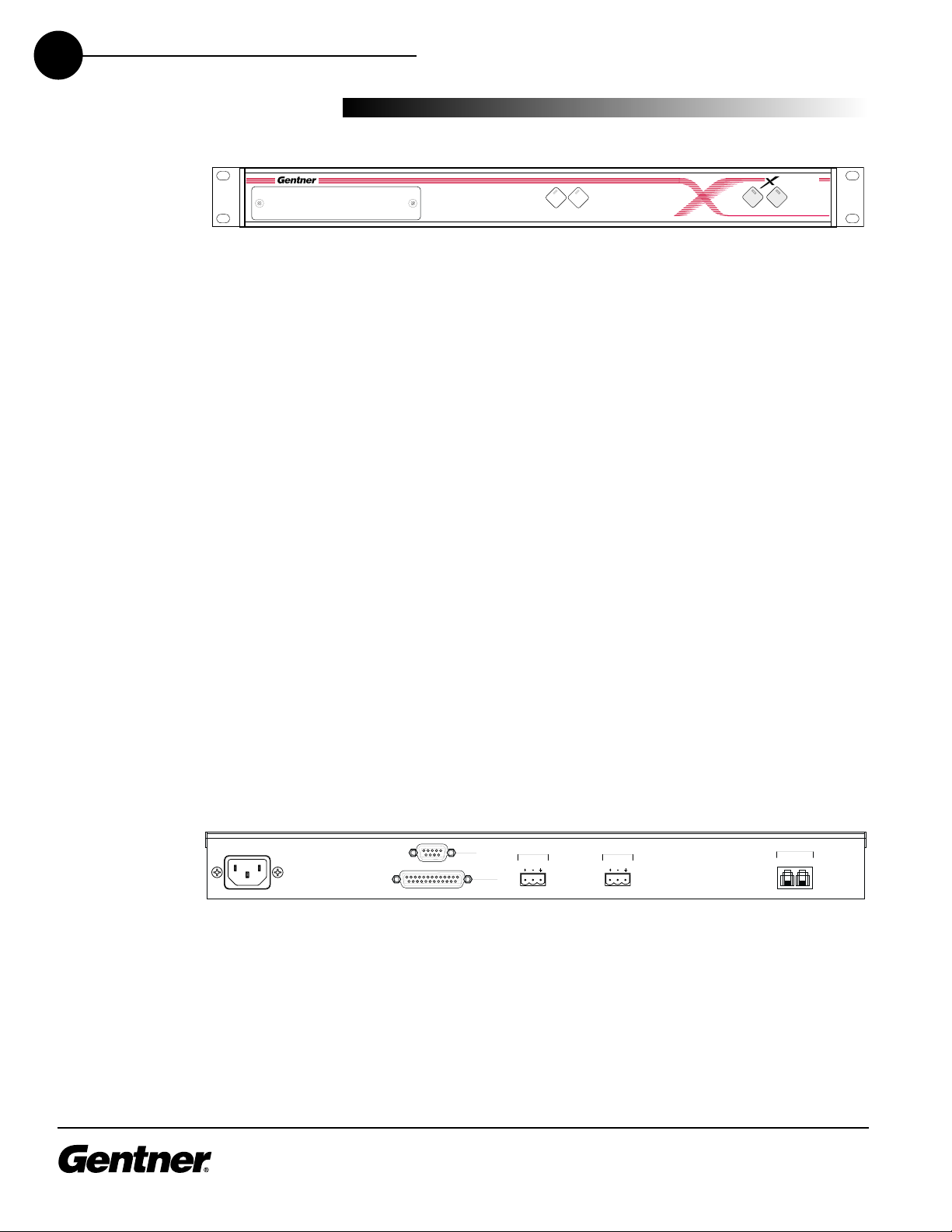
Rear View
The XAP TH1 back-panel connectors (see Figure 3, above) perform the
following functions:
1. Power The AC power cord input is a NEMA type connector allowing
100–240VAC, 50/60Hz.
Transmit
Receive
Controls and
Connections
Figure 2. XAP TH1 front-panel controls
Figure 3. XAP TH1 back-panel connectors
Transmit
Transmit
Receive
Receive
On Off
HAP 1T
VOLTAGE RANGE 100V - 240V 2A
FREQUENCY 50Hz / 60Hz
RS-232
REMOTE
TRANSMIT
INPUT
RECEIVE
OUTPUT
TELCO
LINE SET
Page 9

TECHNICAL SUPPORT: 1.800.283.5936 (USA) OR 1.801.974.3760
5
INTRODUCTION
• CONTROLS AND CONNECTIONS
2. RS-232 This female DB9 serial port provides connection between
the XAP TH1 and a PC or custom remote control.
3. Remote This DB25 connector provides control and status of the
XAP TH1. See Appendix B for pinouts.
4. Transmit Input This Phoenix™ connection provides a non-gated
electronically balanced line level input. The nominal input level is 0
dBu. This line input is mutable. The default setting is off (not muted).
5. Receive Output This Phoenix connection provides a balanced line
level output. The nominal output level is 0 dBm. The outputs adjust
for line imbalances and maintain a constant output level. This line
output is mutable. The default setting is off (not muted).
6. Line This RJ-11 connector provides connection of a standard
analog telephone line to the hybrid.
7. Set This RJ-11 connector allows connection to a standard telephone
set. Tip and ring from the phone line are present at this connector
when the hybrid is in its Off state. Tip and ring from the phone line
are not present at this point when the hybrid is in its On state.
Touch-Tone Dialing
Through the RS-232 (and serial commands), the XAP TH1’s touch-tone
(DTMF) dialing capability can be accessed. This allows outbound calls to
be initiated by the XAP TH1 without requiring an external dialer or
telephone set. This feature continues to function after connection,
enabling the user to issue tones for voice mail/pager interaction. See
Serial Commands on page 15.
Page 10

TECHNICAL SUPPORT: 1.800.283.5936 (USA) OR 1.801.974.3760
6
INTRODUCTION • BEFORE YOU INSTALL
Power Requirements
The XAP TH1 automatically accommodates voltage requirements of
100–240VAC, 50/60Hz, 15W.
Telephone Line Requirements
The XAP TH1 model operates on a standard analog telephone line and
connects to the telephone system with a standard RJ-11C modular jack.
If you do not have an RJ-11C jack where you want to install your XAP
TH1, call your telephone company for installation.
Equipment Placement
The XAP TH1 models are designed for installation into a standard 19inch equipment rack. You can also purchase side panels for desktop
placement.
Before You
Install
Page 11
TECHNICAL SUPPORT: 1.800.283.5936 (USA) OR 1.801.974.3760
2
The XAP TH1 is designed for easy installation and setup. All necessary
interface connections are made through rear-panel connectors. This
makes for easy installation.
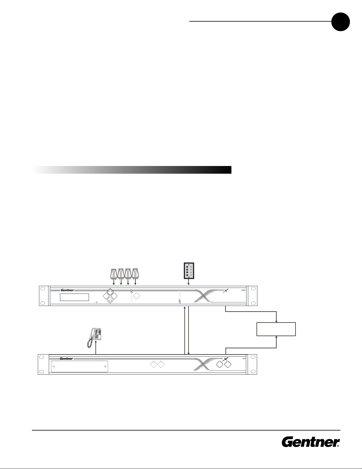
The following block diagram (see Figure 4, below) shows the XAP TH1
when installation is complete in a XAP 800 system.
Installation &
Operation
Installation
INSTALLATION & OPERATION
• INSTALLATION
7
+8
+4
0
-4
-10
-30
Mic On
Figure 4. System diagram
Typical Installation in XAP 800 System
Transmit Receive
Control
Panel
(optional)
1
2
3
4
5
6
7
8
Receive
Output
Transmit
Input
XAP 800
XAP TH1
Microphones
EscEnter
Telephone
Set
Inputs
+12
+8
+4
Meter
0
-4
-10
-30
On Off
0A P 8 0
RS-232
Panja, Crestron, or
other controller
RS-232
HA P T 1
Page 12

TECHNICAL SUPPORT: 1.800.283.5936 (USA) OR 1.801.974.3760
8
INSTALLATION & OPERATION
• INSTALLATION
Connecting the Unit
Refer to XAP TH1 back-panel connections (See Figure 5, below) for a
description and placement of each of the connections you will be
making. Each connector is numbered for easy identification. To install
your XAP TH1, follow these step-by-step instructions:
1. Plug your telephone line from the wall jack into the RJ-11C Line jack
[6].
2. Plug your telephone set into the RJ-11C Set jack [7].
3. If you are using a remote control device (Crestron, Panja AMX, etc.),
connect via the RS-232 port [2]. You can also connect to a PC using
this port.
4. If you are using a remote control for parallel control and hybrid
status, plug it into the DB25 Remote connector [3].
5. Wire the XAP TH1 to the XAP 800 using the provided three-terminal
Phoenix push-on connectors. These connectors are designed for
easy wiring; simply insert the desired wire into the appropriate
connector opening and tighten down the top screw.
Transmit Input Audio connected to the Transmit Input [4] will
be sent down the telephone line.
Receive Output Audio from the Receive Output [5] (telephone
participant audio) is passed to the XAP 800 for further routing
and distribution. See Figure 4 on page 7.
Connecting Power
The power input [1] will operate at any level between 100–240VAC,
50–60Hz, 15W (typical). Plug in the XAP TH1 to complete the hardware
installation.
Figure 6. RJ-11C telephone-line connector
Figure 7. Phoenix push-on connector
Figure 5. XAP TH1 back-panel connectors
The three terminals in the
Phoenix connector corre-
spond with the back-panel
audio contacts (from left to right):
+(positive), –(negative), and
(ground).
✍
VOLTAGE RANGE 100V - 240V 2A
FREQUENCY 50Hz / 60Hz
2
RS-232
REMOTE
TRANSMIT
INPUT
RECEIVE
OUTPUT
TELCO
LINE SET
1
–
+
Ground
Negative
Positive
3
4
5
7
6
Page 13

Figure 8. DIP Switch Settings
TECHNICAL SUPPORT: 1.800.283.5936 (USA) OR 1.801.974.3760
9
INSTALLATION & OPERATION • DIP SWITCH SETTINGS
The XAP TH1 has a variety of operational features configurable through
DIP switch settings, including noise burst/auto-adapt, receive AGC
control, auto-answer, auto-disconnect, call progression/loop, and
receive reduction. Default settings (as shipped from the factory) are
denoted by an asterisk “*”.
DIP Switch 1, Noise Burst/Auto-Adapt
In some applications, it may be desirable to adapt the hybrid with a
white-noise burst, rather than allowing the hybrid to adapt automatically
to line conditions. To enable this feature, DIP switch 1 behind the digital
hybrid’s front panel is used to enable/disable the noise burst (Table 1,
below).
Table 1. Noise Burst Auto-Adapt DIP Switch Settings
DIP Switch P
osition Description
1 ON (UP) Burst adapt
1* OFF (DOWN) Auto-adapt
DIP Switch 2, 6dB Receive Boost
In some applications, it may be desirable to increase the receive audio
by 6dB. To enable this feature, DIP switch 2 behind the digital hybrid’s
front panel is used to enable/disable the 6dB receive boost (Table 2,
below).
Table 2. 6dB Receive Boost DIP Switch Settings
DIP Switch Position Description
2 ON (UP) 6dB Receive audio boost enabled
2* OFF (DOWN) 6dB Receive audio boost disabled
DIP Switch
Settings
3 Receive AGC
4 Auto Answer
5 Auto Disconnect
2 Receive Boost
1 Burst Adapt
7 Receive Reduction
6 Call Progression
8–12 No function
Page 14

TECHNICAL SUPPORT: 1.800.283.5936 (USA) OR 1.801.974.3760
10
INSTALLATION & OPERATION
• DIP SWITCH SETTINGS
DIP Switch 3, Receive Automatic Gain Control
DIP switch 3 behind the digital hybrid’s front access panel enables/
disables the AGC function in the firmware (Table 3, below).
Table 3. Receive AGC DIP Switch Settings
DIP Switch Position Description
3* ON (UP) Receive AGC enabled
3 OFF (DOWN) Receive AGC disabled
DIP Switch 4, Auto-Answer
DIP switch 4 behind the XAP TH1’s front access panel enables/disables
auto-answer (Table 4, below).
Table 4. Auto-Answer DIP Switch Settings
DIP Switch Position Description
4 ON (UP) Auto-answer enabled
4* OFF (DOWN) Auto-answer disabled (follows
the serial command)
DIP Switch 5, Auto-Disconnect
DIP switch 5 behind the XAP TH1’s front access panel enables/disables
auto-disconnect (Table 5, below).
Table 5. Auto-Disconnect DIP Switch Settings
DIP Switch P
osition Description
5* ON (UP) Auto-disconnect enabled
5 OFF (DOWN) Auto-disconnect disabled
DIP Switch 6, Call Progression/Loop
DIP switch 6 selects either loop drop or call-progress mode. Callprogress mode will disconnect the line upon detection of a valid callprogress signal (Table 6, below). Call progress will detect reorder tone
and busy signal for the U.S., Canada, United Kingdom, France, and
Germany.
Table 6. Call Progression/Loop DIP Switch Settings
DIP Switch
P
osition Description
6 ON (UP) Call progression enabled
6* OFF (DOWN) Loop drop enabled
To issue the AA (autoanswer) serial command to
toggle auto-answer, DIP
switch 4 must be OFF (DOWN).
✍
In order for the settings on
DIP Switch 6 to function,
DIP Switch 5 must be ON
(UP). Auto-disconnect must be
enabled before either Call
Progression or Loop Drop are applicable.
✍
Page 15

TECHNICAL SUPPORT: 1.800.283.5936 (USA) OR 1.801.974.3760
11
DIP Switch 7, Receive Reduction
In some applications, it may be necessary to duck the receive audio
coming in through the telephone line when transmit audio is present. To
serve this purpose, DIP switch 7 is designated to duck the receive audio
by -6dB, if active (Table 7, below).
Table 7. Receive Reduction DIP Switch Settings
DIP Switch Position Description
7 ON (UP) Receive reduction enabled
7* OFF (DOWN) Receive reduction disabled
INSTALLATION & OPERATION
• CALIBRATION
The following information will help you make adjustments to optimize
your system performance. Verify all components and all connections.
Ensure that proper power is supplied to the XAP TH1 and that the unit is
OFF (the red OFF LED [4] will be lit; see Figure 9, below). If the green
ON LED [3] is lit, press the OFF button [6].
There are two calibration methods for the XAP TH1: noise burst and
auto-adapt. Which procedure is used depends on whether you have DIP
switch 1 ON (UP) for noise-burst adapt, or DIP switch 1 OFF (DOWN) for
auto-adapt. Either will suffice to calibrate the XAP TH1. The difference is
the application and/or personal preference. Some applications are not
suited for a .75-second noise burst, and may require the gradual
adaptation over time.
Noise-Burst Adapt
If DIP switch 1 is ON (UP), have someone call the XAP TH1 from another
location. Answer the line by pressing the ON button [5]. (If the autoanswer feature is active, the unit will answer the call after one complete
ring.)
The caller will hear a short white noise burst (it will sound like static) and
a short beep. This automatically adapts the XAP TH1 to the telephone
line.
Transmit
Receive
Calibration
Figure 9. XAP TH1 front-panel controls
Some echo and ringing may
be heard while the XAP TH1
is calibrating. Disregard it
and continue with calibration until
the end of the procedure. The echo
and ringing will disappear.
✍
12
Transmit
Receive
Transmit
Receive
3
HAP T 1
On Off
5
4
6
Page 16

TECHNICAL SUPPORT: 1.800.283.5936 (USA) OR 1.801.974.3760
12
INSTALLATION & OPERATION • CALIBRATION
Auto-Adapt
If DIP switch 1 is OFF (DOWN), call someone and continue to talk while
the system adapts over time. Once complete, the XAP TH1 will be fully
calibrated and ready for use.
Conclude your conversation and press the OFF button [6]. (If the autodisconnect feature is active, and the distant location hangs up, the XAP
TH1 will disconnect upon sensing loop drop or call-progress tones,
depending on the position of DIP switch 6.)
Transmit Level Adjustment
Someone in the local room should speak into the microphone at a
normal distance, in a normal voice. The party at the distant location
should not speak during the transmit adjustment. Adjust the XAP 800
output that is connected to the XAP TH1 TRANSMIT input to nominal 0
reaching peaks of +4dB to +8dB. The XAP TH1 TRANSMIT LED [1]
should be solid green while the person is speaking and extinguish when
the person stops. Refer to your XAP 800 manual for more information.
Receive Level Adjustment
Someone in the distant location should speak into the microphone at a
normal distance, in a normal voice; the local room should maintain
silence. Adjust the XAP 800 input that is connected to the XAP TH1
RECEIVE output to to nominal 0 reaching peaks of +4dB to +8dB. The
XAP TH1 RECEIVE LED [2] should be solid green while the person is
speaking and extinguish when the person stops.
Calibration is now complete.
XAP TH1 transmit and
receive audio level
adjustments are made via
the XAP 800. Nominal transmit and
receive level for the XAP TH1 is
0dB.
✍
Page 17

TECHNICAL SUPPORT: 1.800.283.5936 (USA) OR 1.801.974.3760
13
INSTALLATION & OPERATION
• OPERATING YOUR XAP TH1
Easy-to-access front-panel controls make operation of the XAP TH1
simple. Figure 10 (below) shows each front panel LED and button by
number.
Answering a Call
An incoming call will ring on the telephone set connected to the XAP
TH1 and flash the ON LED. You can answer the call in one of two ways:
Press the ON button [5] on either the front panel or from your
remote control. This will route the call through the XAP TH1 to the
XAP 800. The green ON LED [3] will light. The red OFF LED [4] will
extinguish. Upon connection, the XAP TH1 automatically (if DIP
switch is set to Off) adjusts to the line conditions.
Answer the call by picking up the telephone handset and talking to
your party over the telephone.
Making a Call
Call the party normally, using your handset. After the other party has
answered, route the call through the XAP TH1 by pressing the ON
button [5]. The ON LED [3] will light and the XAP TH1 will take control of
the call, disabling the telephone set. You may now safely hang up the
handset without disconnecting your call. When the conversation is
complete, press the OFF button [6] to disconnect the call.
If using RS-232 touch tone, it is not necessary to hit the ON button [5].
When using the DIAL serial port command, the XAP TH1 automatically
engages the hybrid. See Serial Commands, page 15.
Disconnecting a Call
If the call is routed through the XAP TH1 (the ON LED [3] will glow),
press the OFF button [6] (OFF LED [4] will glow, ON LED [3] will
extinguish).
If your call is through the handset only (the red OFF LED [4] will be lit),
hang up when the conversation is complete.
Operating
Your XAP TH1
Transmit
Receive
Figure 10. XAP TH1 front-panel controls
If auto-answer is enabled
(DIP switch 4), the XAP TH1
will answer after the first
complete ring.
✍
If auto-disconnect is
enabled (DIP switch 5), the
XAP TH1 will disconnect
upon sensing loop drop or callprogress tones (depending on the
position of DIP switch 6).
✍
12
Transmit
Receive
Transmit
Receive
3
HAP T 1
On Off
5
4
6
Page 18

TECHNICAL SUPPORT: 1.800.283.5936 (USA) OR 1.801.974.3760
14
INSTALLATION & OPERATION
• OPERATING YOUR XAP TH1
Remote Connector (DB25) Option
A customer-supplied remote control or contact-closure switch can be
used to perform three functions: mute on/off, system on, and system off.
For pinouts, see Connector Pinouts, page 23.
Custom Controller (RS-232) Option
The XAP products are designed to function with custom serial control
systems such as Crestron and Panja (AMX). The controller is connected
to the XAP TH1 RS-232 port. Via the custom controller, the XAP TH1 can
be turned on or off; transmit and receive audio can be muted; DTMF
tones can be generated (See Serial Commands, Page 15); telephone
hybrid can be renulled; input and output can be metered; and ERL and
ERLE can be read.
When Not in Use
The XAP TH1 is inactive when the red OFF LED [4] is lit.
Page 19

TECHNICAL SUPPORT: 1.800.283.5936 (USA) OR 1.801.974.3760
A
The XAP TH1 accepts serial commands via the RS-232 serial port. The
RS-232 serial port default protocol is 9,600, 8 bits, 1 stop bit, no parity.
The commands in this section pertain only to the XAP TH1.
Command Structure
The structure of serial commands is as follows:
The command, then any additional options in the order that they appear
in the command descriptions on the following pages.
Example: A command to enable auto-answer on the XAP TH1 would
have the command line: AA 1. In this command line, AA=command,
1=on state). If a command calls for a “null” value, leave a blank in the
command line (e.g. “AA” would return the current state of auto-answer
on the TH1).
Commands can use uppercase or lowercase letters. Return values
always use uppercase letters. In order for a command to be recognized
by the serial port, the command must be terminated by a carriage
return.
Appendix A
Serial Commands
APPENDIX A • SERIAL COMMANDS
15
Page 20

TECHNICAL SUPPORT: 1.800.283.5936 (USA) OR 1.801.974.3760
16
APPENDIX A • SERIAL COMMANDS
Conventions
The following typographic conventions are used to set off parameters
and explain their function in command strings.
Convention
Example Description
< > <X> Mandatory parameters
[ ] [X] Optional parameters
– 1–8 Range between the values
, 4,7,9 List of available values
bold AA Command
AA
This command activates and deactivates the auto-answer feature.
AA <X>
Explanation: <X> is the action (i.e. auto-answer enable, auto-answer
disable, current state).
X=0 Parameter disables auto-answer
X=1 Parameter enables auto-answer
X=2 Parameter to toggle the state from one state to
the other (regardless of current state)
X= Null Parameter to report back the current state
This serial command only
functions if DIP switch 4 is
OFF (DOWN).
✍
XAP TH1 Serial Commands
Command Function Command Function
AA Auto-answer RING Ring acknowledgement
DIAL Dial touch-tones
HOOK Send hook-flash to the line
HOOKD Set hook- flash duration TERL Return telephone ERL
LVL Return transmit/receive level TERLE Return telephone ERLE
MUTE Control/report mute status* VER Return current version of software
NULL Renulls XAP TH1 to telephone line
* applied to a specific channel
RINGEN .Changes or reports the state of ring indication
TE
Control/report the connect state of the unit
Page 21

TECHNICAL SUPPORT: 1.800.283.5936 (USA) OR 1.801.974.3760
17
APPENDIX A • SERIAL COMMANDS
DIAL
DTMF tones can be generated through the XAP TH1. This capability
remains active after a call is placed, so tones can be issued for use with
voice mail and pagers.
If the XAP TH1 is not connected when this command is issued, the unit
will connect to the line first, then dial the tone(s).
DIAL <STRING>
Explanation: <STRING> is any valid combination of touch tone
characters. A comma indicates a two-second pause. STRING has a
maximum length of 40 characters. Valid characters are: 0 through 9, #, *
and ,
Return Values: DIAL returns the dialed string of numbers. The string is
returned after the command has been completed (i.e. dialed all the
touch tones).
Example: The following command dials the number (801) 975-7200.
A 9 and a pause is generated to get an outside line on a PBX.
The number to be dialed: DIAL 9,8019757200
The following is returned out the serial port: DIAL 9,8019757200
HOOK
This command sends a momentary interruption in line seizure (hook
flash) to the telephone line. This command is write only.
HOOK
Return Values: If hook flash succeeded, the following is returned out
the serial port: HOOK
Example:
The following command request hook flash: HOOK
The following is returned out the serial port: HOOK
Page 22

TECHNICAL SUPPORT: 1.800.283.5936 (USA) OR 1.801.974.3760
18
APPENDIX A • SERIAL COMMANDS
HOOKD
This command changes or reports the hook-flash duration of the unit.
HOOKD <X>
Explanation: <X> is the action (i.e. hook-flash duration, current state)
X=0 Parameter to set hook-flash duration to 50 ms
X=1 Parameter to set hook-flash duration to 90 ms
X=2 Parameter to set hook-flash duration to 100 ms
X=3 Parameter to set hook-flash duration to 110 ms
X=4 Parameter to set hook-flash duration to 250 ms
X=5 Parameter to set hook-flash duration to 300 ms
X=6 Parameter to set hook-flash duration to 400 ms
X=7 Parameter to set hook-flash duration to 500 ms
X=8 Parameter to set hook-flash duration to 600 ms
X=9 Parameter to set hook-flash duration to 700 ms
X=Null Parameter to report back the current state.
Return Values: The command will return the hook-flash duration of the
unit in the same format as the command. HOOKD <X>
Example: The following command requests hook-flash duration:
HOOKD
The following is returned out the serial port: HOOKD 4
LVL
This command reports back the transmit or receive level for a unit.
LVL <CH>
Explanation: <CH> is which parameter to be measured.
CH= RXIN Parameter for level from the telephone line
CH=RXOUT Parameter for level from the XAP TH1
CH=TXIN Parameter for level into the XAP TH1
CH=TXOUT Parameter for level to the telephone line
Return Values: LVL will return the output level of the line channel in the
same format as the command.
Example: If is current level for RXIN channel is -20dBu, the following is
returned out the serial port:
LVL RXIN -20
Page 23

TECHNICAL SUPPORT: 1.800.283.5936 (USA) OR 1.801.974.3760
19
APPENDIX A • SERIAL COMMANDS
MUTE
This command controls or reports the mute status of a channel.
MUTE <CH> <X>
Explanation:
<CH> is the channel(s) to be muted/unmuted.
CH=T Parameter to apply to the transmit channel
CH=R Parameter to apply to the receive channel
CH=* Parameter to apply to both channels
<X> is the action (i.e. mute, unmute, report the mute state).
X=0 Set mute to off
X=1 Set mute to on (mute the selected channel)
X=2 Parameter to toggle the state from one state to
the other (regardless of current state)
X=NULL Report the current state of mute for the
selected channel
Return Values: MUTE returns the mute status in the same format as the
command.
Example: If current state of mute for channel T is muted, the following
is returned out the serial port: MUTE T 1
If current state of mute for channel T is unmuted, the following is
returned out the serial port: MUTE T 0
NULL
This command sends a short noise burst down the telephone line and
forces the XAP TH1 to adapt to the telephone line. This command is
write only.
NULL
Return Values: If the renull succeeded, the following is returned out
the serial port: NULL
RING
When the XAP TH1 receives a valid ring from the telephone line, the XAP
TH1 will respond.
RING
Page 24

TECHNICAL SUPPORT: 1.800.283.5936 (USA) OR 1.801.974.3760
20
APPENDIX A • SERIAL COMMANDS
RINGEN
This command changes or reports back the state of the ring indication.
RINGEN <X>
Explanation: <X> is the action (i.e. which ring indication, current state)
X=0 Parameter to set the state to OFF
X=1 Parameter to set the state to ON
X=2 Parameter to toggle the state from one state to
the other (regardless of current state)
X= Null Parameter to report back the current state.
Return Values: The command will return the updated condition of the
ring indication in the same format as the command.
TE
Controls and reports the connection status of the unit.
TE <X>
Explanation: <X> is the action (e.g. connect, disconnect, current state)
X=0 Parameter to set the unit to disconnect from
the line
X=1 Parameter to set the unit to connect to the line
X=2 Parameter to toggle the state from one state to
the other (regardless of current state)
X= Null Parameter to report back the current state.
Return Values: If the current connect state is ON, the following is
returned out the serial port: TE 1
If the current connect state is OFF, the following is returned out the
serial port: TE 0
Example:
The following connects the unit to the telephone line: TE 1
The following is returned out the serial port: TE 1
The following reports the connection state of the unit: TE
The following is returned out the serial port: TE 1
Page 25

TECHNICAL SUPPORT: 1.800.283.5936 (USA) OR 1.801.974.3760
APPENDIX A • SERIAL COMMANDS
21
TERL
This command reports back the telephone echo return loss (ERL) for
the XAP TH1 in dB. This is a read-only parameter.
TERL
Return Values: If the current TERL level for the telephone canceller is
10 dB, the following is returned out the serial port:
TERL 10
TERLE
This command reports back the telephone echo return loss enhancement (ERLE) for the XAP TH1 in dB. This is a read-only parameter.
TERLE
Return Values: If the current TERLE level for the telephone canceller is
20dB, the following is returned out the serial port:
TERLE 20
VER
This command returns current version of software. This version is unique
to a released version of software. This command is read only.
VER
Return Values: VER returns the version of software (a major version
number followed by a period and a minor version number).
Example: The following command requests the version number: VER
The following is returned out the serial port: VER 1.0
Page 26

TECHNICAL SUPPORT: 1.800.283.5936 (USA) OR 1.801.974.3760
22
Page 27

TECHNICAL SUPPORT: 1.800.283.5936 (USA) OR 1.801.974.3760
B
Remote Connector Pinout
Pin Description
Pin Description
1 Remote ON * 14 ON indication **
2 Remote OFF * 15 OFF indication **
3 N/C 16 N/C
4 N/C 17 N/C
5 Switch/Indicator Common 18 Switch/Indicator Common
6 Transmit Presence Indicator ** 19 N/C
7 Receive Presence Indicator ** 20 N/C
8 N/C 21 Switch/Indicator Common
9 Unbalanced Transmit Audio Input (0dBu nominal) 22 Audio Common
10 Unbalanced Receive Audio Output (0dBu nominal) 23 Audio Common
11 N/C 24 Audio Common
12 N/C 25 Switch/Indicator Common
13 Audio Common
* Remote control provided via contact closure to Switch/Indicator Common
** Remote indicators provided via open collector outputs to Indicator Common (<15V, <39mA)
RS-232 Com Port
Pin Description Pin Description
1 Not used 6 Not used
2 TXD 7 Not used
3 RXD 8 Not used
4 Not used 9 Not used
5 Ground
Appendix B
APPENDIX B • PINOUTS
23
Pinouts
Page 28

TECHNICAL SUPPORT: 1.800.283.5936 (USA) OR 1.801.974.3760
24
APPENDIX B • PINOUTS
Set Connector Pinout
Pin Description Pin Description
1 To pin 6 of SET RJ-11C 4 Tip
2 To pin 5 of SET 5 To pin 2 of LINE
3 Ring 6 To pin 1 of LINE RJ-11C
Line Connector Pinout
Pin Description Pin Description
1 To pin 6 of LINE RJ-11C 4 Ring
2 To pin 5 of LINE 5 To pin 2 of SET
3 Tip 6 To pin 1 of SET RJ-11C
Page 29

TECHNICAL SUPPORT: 1.800.283.5936 (USA) OR 1.801.974.3760
C
DIMENSIONS
17"/43.2cmW x 1.75"/4.5cmH x
8"/25.4cmD
WEIGHT
7 lb/3.18 kg (dry)
12 lb/5.4 kg (shipping)
REAR PANEL CONNECTORS
POWER: IEC Type
Auto-adjusting power module from
100–240 VAC, 50/60Hz, 15W (typical)
REMOTE: DB25 female connector.
Remote Transmit Input:
0dBu nominal, unbalanced 10kOhm
impedance
Remote Receive:
0dBu nominal, unbalanced, 50 Ohm
impedance
Control Inputs:
Remotely activate functions with a
momentary switch closure to ground
Status Outputs:
Remotely check the status outputs.
Status outputs are open collector out
puts rated at 30VDC and 40mA maximum.
RS-232:DB9 female
9600, 8 bits, 1 stop bit, no parity
TRANSMIT INPUT:
Push-on terminal block with slotted setscrew connectors contacts provided at
terminal block at +20dBm maximum input,
0dBu nominal level, balanced bridging
>20kOhm impedance
RECEIVE OUTPUT:
Push-on terminal block with slotted setscrew connectors contacts provided at
terminal block at +20dBm maximum input,
0dBu nominal level, <50 Ohm impedance
TELCO LINE: RJ-11 connector
POTS (plain old telephone service)
telephone line or analog extension from a
PBX. A-Lead Supervision provided
TELCO SET: RJ-11 connector
A-Lead Supervision provided
FRONT PANEL CONNECTORS
CONTROLS:
On Button
Off Button
STATUS LEDS:
Transmit Audio Presence
Receive Audio Presence
Appendix C
Specifications
APPENDIX C• SPECIFICATIONS
25
Page 30

TECHNICAL SUPPORT: 1.800.283.5936 (USA) OR 1.801.974.3760
26
TELEPHONE TRANSMIT
Nominal send input of 0dBu referenced to
-15dBu onto the telephone line.
FREQUENCY RESPONSE:
±1dB from 250Hz to 3.3kHz (AGC disabled)
SIGNAL-TO-NOISE RATIO:
>56dB reference to 0dBu at -15dBm on
the telephone line
RECEIVE AUDIO DISTORTION
<.3%
TELEPHONE RECEIVE
Nominal phone line level of -15dBu
referenced to caller output of 0dBu
FREQUENCY RESPONSE:
±1dB from 250Hz to 3.3kHz (AGC disabled)
SIGNAL-TO-NOISE RATIO:
>56dB reference to 0dBu at -15dBm on
the telephone line
RECEIVE AUDIO DISTORTION
<.3%
ECHO CANCELLATION
NULL: 55dB nominal
TAIL TIME: 31ms
OPERATING TEMPERATURE
32–100˚ F / 0–38˚ C
HUMIDITY
0–80 percent
All specifications are subject to change
without notice.
APPENDIX C • SPECIFICATIONS
Page 31

TECHNICAL SUPPORT: 1.800.283.5936 (USA) OR 1.801.974.3760
27
APPENDIX C • WARRANTY
Gentner Communications Corporation (Manufacturer) warrants that this
product is free of defects in both materials and workmanship. Should
any part of this equipment be defective, the Manufacturer agrees, at its
option, to:
A. Repair or replace any defective part free of charge (except
transportation charges) for a period of one year from the date of the
original purchase, provided the owner returns the equipment to the
Manufacturer at the address set forth below. No charge will be made for
parts or labor during this period;
B. Furnish replacement for any defective parts in the equipment for a
period of one year from the date of original purchase. Replacement
parts shall be furnished without charge, except labor and transportation.
This Warranty excludes assembled products not manufactured by the
Manufacturer whether or not they are incorporated in a Manufacturer
product or sold under a Manufacturer part or model number.
THIS WARRANTY IS VOID IF:
A. The equipment has been damaged by negligence, accident, act of
God, or mishandling, or has not been operated in accordance with the
procedures described in the operating and technical instructions; or,
B. The equipment has been altered or repaired by other than the
Manufacturer or an authorized service representative of the
Manufacturer; or,
C. Adaptations or accessories other than those manufactured or
provided by the Manufacturer have been made or attached to the
equipment which, in the determination of the Manufacturer, shall have
affected the performance, safety or reliability of the equipment; or,
D. The equipment’s original serial number has been modified or
removed.
NO OTHER WARRANTY, EXPRESS OR IMPLIED, INCLUDING
WARRANT Y OF MERCHANTABILITY OR FITNESS FOR ANY PARTICULAR
USE, APPLIES TO THE EQUIPMENT, nor is any person or company
authorized to assume any warranty for the Manufacturer or any other
liability in connection with the sale of the Manufacturer's products.
Manufacturer does not assume any responsibility for consequential
Warranty
Page 32

TECHNICAL SUPPORT: 1.800.283.5936 (USA) OR 1.801.974.3760
28
APPENDIX C • WARRANTY
damages, expenses, or loss of revenue or property, inconvenience, or
interruption in operation experienced by the customer due to a
malfunction in the purchased equipment. No warranty service
performed on any product shall extend the applicable warranty period.
In case of unsatisfactory operation, the purchaser shall promptly notify
the Manufacturer at the address set forth below in writing, giving full
particulars as to the defects or unsatisfactory operation. Upon receipt of
such notice, the Manufacturer will give instructions respecting the
shipment of the equipment, or such other matters as it elects to honor
this warranty as above provided. This warranty does not cover damage
to the equipment during shipping and the Manufacturer assumes no
responsibility for such damage. All shipping costs shall be paid by the
customer.
This warranty extends only to the original purchaser and is not
assignable or transferable.
Gentner Communications Corporation, 1825 Research Way, Salt
Lake City, Utah 84119
FCC Part 15 Compliance
This equipment has been tested and found to comply with the limits for
a Class A digital device, pursuant to Part 15 of the FCC rules. These
limits are designed to provide reasonable protection against harmful
interference when the equipment is operated in a commercial
environment. This equipment generates, uses, and can radiate radio
frequency energy and, if not installed and used in accordance with the
instruction manual, may cause harmful interference to radio
communications. Operation of this equipment in a residential area is
likely to cause harmful interference, in which case the user will be
required to correct the interference at his/her own expense.
Changes or modifications not expressly approved by Gentner
Communications Corporation could void the user’s authority to operate
the equipment.
Compliance
Page 33

TECHNICAL SUPPORT: 1.800.283.5936 (USA) OR 1.801.974.3760
29
APPENDIX C • COMPLIANCE
FCC Part 68 Compliance
FCC Registration Number: FBIUSA-43110-BR-T
Ringer Equivalence Number (REN): 0.6B
A label containing, among other information, the FCC registration
number and Ringer Equivalence Number (REN) for this equipment is
prominently posted on the top plate, near the rear of the equipment. If
requested, this information must be provided to your telephone
company.USOC Jacks: This device uses RJ-11C and RJ21X terminal
jacks.
The REN is used to determine the quantity of devices which may be
connected to the telephone line. Excessive RENs on the telephone line
may result in the devices not ringing in response to an incoming call. In
most, but not all areas, the sum of the RENs should not exceed five (5).
To be certain of the number of devices that may be connected to the
line, as determined by the total RENs, contact the telephone company
to obtain the maximum RENs for the calling area.
If this equipment causes harm to the telephone network, the telephone
company will notify you in advance that temporary discontinuance of
service may be required. If advance notice is not practical, the
telephone company will notify the customer as soon as possible. Also,
you will be advised of your right to file a complaint with the FCC if you
believe it is necessary.
The telephone company may make changes in its facilities, equipment,
operations, or procedures that could affect the operation of the
equipment. If this happens, the telephone company will provide
advance notice for you to make the necessary modifications in order to
maintain uninterrupted service.
If you experience problems with this equipment, contact Gentner
Communications Corporation, 1825 Research Way, Salt Lake City, Utah
84119, or by phone at (801) 975-7200 for repair and warranty
information. If the trouble is causing harm to the telephone network, the
telephone company may request you remove the equipment from the
network until the problem is resolved.
No user serviceable parts are contained in this product. If damage or
malfunction occurs, contact Gentner Communications for instructions
on its repair or return.
This equipment cannot be used on telephone company provided coin
service. Connection to Party Line Service is subject to state tariffs.
Page 34

TECHNICAL SUPPORT: 1.800.283.5936 (USA) OR 1.801.974.3760
30
APPENDIX C • COMPLIANCE
IC Compliance
Ringer Equivalence Number (REN): 0.6B
IC Certification Number: 1970 11504 A
NOTICE: The Industry of Canada label identifies certified equipment.
This certification means that the equipment meets certain telecommunications network protective operational and safety requirements. The
Department does not guarantee the equipment will operate to the
user's satisfaction.
Before installing this equipment, users should ensure that it is permissible to be connected to the facilities of the local telecommunications
company. The equipment must also be installed using an acceptable
method of connection. In some cases, the company's inside wiring
associated with a single line individual service may be extended by
means of a certified connector assembly (telephone extension cord).
The customer should be aware that compliance with the above conditions may not prevent degradation of service in some situations.
Repairs to certified equipment should be made by an authorized
Canadian maintenance facility designated by Gentner
Communications. Any repairs or alterations made by the user to this
equipment, or equipment malfunctions, may give the
telecommunications company cause to request the user to disconnect
the equipment.
Users should ensure for their own protection that the electrical ground
connections of the power utility, telephone lines and internal metallic
water pipe system, if present, are connected together. This precaution
may be particularly important in rural areas.
Safety Information
CAUTION: Users should not attempt to make such connections
themselves, but should contact the appropriate electrical inspection
authority, or electrician, as appropriate.
European Compliance
This equipment has been approved in accordance with Council
Decision 98/482/EC for pan-European single terminal connection to
the public switched telephone network (PSTN). However, due to differences between the individual PSTNs provided in different countries, the
approval does not, of itself, give an unconditionally assurance of successful operation on every PSTN network termination point. In the event
of problems, you should contact your equipment supplier in the first
instance.
Page 35

TECHNICAL SUPPORT: 1.800.283.5936 (USA) OR 1.801.974.3760
31
APPENDIX C • COMPLIANCE
Gentner Communications Corporation of 1825 Research way, Salt Lake
City, Utah 84119, U.S.A. declares that this equipment is designed to be
compatible with the following networks: Austria, Belgium, Denmark,
Finland, France, Germany, Greece, Iceland, Ireland, Italy, Liechtenstein,
Luxembourg, The Netherlands, Norway, Portugal, Spain, Sweden,
Switzerland, and United Kingdom.
This equipment complies with the requirements of the EU
guidelines:
89/336/EEC “Electromagnetic Compatibility”
73/23/EEC “Electrical operating material for use within spe-
cific voltage limits”
1999/5/EC “Radio Equipment and Telecommunications
Equipment”
Conformity of the equipment with the above guidelines is attested by
the CE mark.
Page 36

TECHNICAL SUPPORT: 1.800.283.5936 (USA) OR 1.801.974.3760
APPENDIX C • BLOCK DIAGRAM
32
UNBALANCED
UNBALANCED
RS–232
 Loading...