

Page 1

XAP™ 400 Audio Conferencing System
Installation & Operation Manual
Page 2

ii
2002 ClearOne Communications, Inc. All
©
rights reser ved. No part of this document
may be reproduced in any form or by any
means without w ritten permission from
learOne Communications. Printed in the
C
United States of America. ClearOne
Communications reserves specific privileges.
nformation in this document is subject to
I
change without notice.
XAP 400 Installation and
Operation Manual
ClearOne Part No. 800-151201 July 2002 (Rev. 2.1)
Technical Services Group ~ 1-800-283-5936 (USA) ~ 1-801-974-3760
Page 3

XAP 400 Installation and Operation Manual
Table of Contents
CHAPTER 1: Introduction . . . . . . . . . . . . . . . . . . . . . . . . . .1
Features . . . . . . . . . . . . . . . . . . . . . . . . . . . . . . . . . . . . . . . . . . . . . . . . . . . .1
Professional Services Group . . . . . . . . . . . . . . . . . . . . . . . . . . . . . . . . . . . . .2
Product registration . . . . . . . . . . . . . . . . . . . . . . . . . . . . . . . . . . . . .3
Product returns . . . . . . . . . . . . . . . . . . . . . . . . . . . . . . . . . . . . . . . . .3
Unpacking . . . . . . . . . . . . . . . . . . . . . . . . . . . . . . . . . . . . . . . . . . . . . . . . . .3
Controls and Connections . . . . . . . . . . . . . . . . . . . . . . . . . . . . . . . . . . . . . . .4
Front panel . . . . . . . . . . . . . . . . . . . . . . . . . . . . . . . . . . . . . . . . . . . .4
Rear panel . . . . . . . . . . . . . . . . . . . . . . . . . . . . . . . . . . . . . . . . . . . .5
iii
Networking . . . . . . . . . . . . . . . . . . . . . . . . . . . . . . . . . . . . . . . . . . . . . . . . . .6
Expansion bus . . . . . . . . . . . . . . . . . . . . . . . . . . . . . . . . . . . . . . . . .6
Operational Requirements . . . . . . . . . . . . . . . . . . . . . . . . . . . . . . . . . . . . . . .7
Power . . . . . . . . . . . . . . . . . . . . . . . . . . . . . . . . . . . . . . . . . . . . . . .7
Telephone line . . . . . . . . . . . . . . . . . . . . . . . . . . . . . . . . . . . . . . . . .7
Equipment placement . . . . . . . . . . . . . . . . . . . . . . . . . . . . . . . . . . . .8
Environmental . . . . . . . . . . . . . . . . . . . . . . . . . . . . . . . . . . . . . . . . .8
CHAPTER 2: Installation . . . . . . . . . . . . . . . . . . . . . . . . . . .9
Hardware Setup . . . . . . . . . . . . . . . . . . . . . . . . . . . . . . . . . . . . . . . . . . . . . .9
To connect the unit . . . . . . . . . . . . . . . . . . . . . . . . . . . . . . . . . . . . . .10
Networking Units . . . . . . . . . . . . . . . . . . . . . . . . . . . . . . . . . . . . . . . . . . . . .11
Expansion bus connections . . . . . . . . . . . . . . . . . . . . . . . . . . . . . . . . .11
Device IDs . . . . . . . . . . . . . . . . . . . . . . . . . . . . . . . . . . . . . . . . . . . .12
Mixer mode . . . . . . . . . . . . . . . . . . . . . . . . . . . . . . . . . . . . . . . . . . .12
LCD Programming . . . . . . . . . . . . . . . . . . . . . . . . . . . . . . . . . . . . . . . . . . . .13
LCD menu tree . . . . . . . . . . . . . . . . . . . . . . . . . . . . . . . . . . . . . . . . .13
System menu . . . . . . . . . . . . . . . . . . . . . . . . . . . . . . . . . . . . . . . . . . .14
RS-232 menu . . . . . . . . . . . . . . . . . . . . . . . . . . . . . . . . . . . . . . . . . .15
Meter menu . . . . . . . . . . . . . . . . . . . . . . . . . . . . . . . . . . . . . . . . . . .16
Inputs menu . . . . . . . . . . . . . . . . . . . . . . . . . . . . . . . . . . . . . . . . . . .18
Outputs menu . . . . . . . . . . . . . . . . . . . . . . . . . . . . . . . . . . . . . . . . . .18
Technical Services Group ~ 1-800-283-5936 (USA) ~ 1-801-974-3760
Page 4

iv
CHAPTER 3: System Configuration . . . . . . . . . . . . . . . . . . .21
G-Ware Requirements . . . . . . . . . . . . . . . . . . . . . . . . . . . . . . . . . . . . . . . . . .21
Creating floppy disk copies . . . . . . . . . . . . . . . . . . . . . . . . . . . . . . . .22
Installing G-Ware . . . . . . . . . . . . . . . . . . . . . . . . . . . . . . . . . . . . . . . . . . . . .22
Site Setup . . . . . . . . . . . . . . . . . . . . . . . . . . . . . . . . . . . . . . . . . . . . . . . . . . .23
Creating a new site . . . . . . . . . . . . . . . . . . . . . . . . . . . . . . . . . . . . . .23
Adding a XAP 400 . . . . . . . . . . . . . . . . . . . . . . . . . . . . . . . . . . . . . .24
Configuring Unit Properties . . . . . . . . . . . . . . . . . . . . . . . . . . . . . . . .25
G-Ware Screens . . . . . . . . . . . . . . . . . . . . . . . . . . . . . . . . . . . . . . . . . . . . . .27
Flow Screen . . . . . . . . . . . . . . . . . . . . . . . . . . . . . . . . . . . . . . . . . . .27
Matrix Screen . . . . . . . . . . . . . . . . . . . . . . . . . . . . . . . . . . . . . . . . . .27
Audio Routing . . . . . . . . . . . . . . . . . . . . . . . . . . . . . . . . . . . . . . . . . . . . . . . .30
Expansion bus O—Z routing . . . . . . . . . . . . . . . . . . . . . . . . . . . . . . . .30
Process A—D routing . . . . . . . . . . . . . . . . . . . . . . . . . . . . . . . . . . . . .30
Cross point attenuation . . . . . . . . . . . . . . . . . . . . . . . . . . . . . . . . . . .30
Matrix report . . . . . . . . . . . . . . . . . . . . . . . . . . . . . . . . . . . . . . . . . .31
Inputs and outputs . . . . . . . . . . . . . . . . . . . . . . . . . . . . . . . . . . . . . . . . . . . .32
Inputs 1—4 . . . . . . . . . . . . . . . . . . . . . . . . . . . . . . . . . . . . . . . . . . . .32
Inputs 5—8 . . . . . . . . . . . . . . . . . . . . . . . . . . . . . . . . . . . . . . . . . . . .44
Outputs 1—9 . . . . . . . . . . . . . . . . . . . . . . . . . . . . . . . . . . . . . . . . . . .46
Expansion Buses . . . . . . . . . . . . . . . . . . . . . . . . . . . . . . . . . . . . . . . . . . . . . .48
From Expansion Bus O—Z . . . . . . . . . . . . . . . . . . . . . . . . . . . . . . . . .48
To Expansion Bus O—Z . . . . . . . . . . . . . . . . . . . . . . . . . . . . . . . . . . .48
Processing . . . . . . . . . . . . . . . . . . . . . . . . . . . . . . . . . . . . . . . . . . . . . . . . . .49
Processing A—D . . . . . . . . . . . . . . . . . . . . . . . . . . . . . . . . . . . . . . . . .49
Telco Setup . . . . . . . . . . . . . . . . . . . . . . . . . . . . . . . . . . . . . . . . . . . . . . . . . .55
To configure telco settings . . . . . . . . . . . . . . . . . . . . . . . . . . . . . . . . .55
Telco Transmit and Receive . . . . . . . . . . . . . . . . . . . . . . . . . . . . . . . . . . . . . .57
Telco Transmit . . . . . . . . . . . . . . . . . . . . . . . . . . . . . . . . . . . . . . . . . .57
Telco Receive . . . . . . . . . . . . . . . . . . . . . . . . . . . . . . . . . . . . . . . . . . .58
CHAPTER 4: Advanced Configuration . . . . . . . . . . . . . . . . .59
Presets . . . . . . . . . . . . . . . . . . . . . . . . . . . . . . . . . . . . . . . . . . . . . . . . . . . . .59
Overview . . . . . . . . . . . . . . . . . . . . . . . . . . . . . . . . . . . . . . . . . . . . . .59
Creating Presets . . . . . . . . . . . . . . . . . . . . . . . . . . . . . . . . . . . . . . . .59
Running presets . . . . . . . . . . . . . . . . . . . . . . . . . . . . . . . . . . . . . . . . .64
Technical Services Group ~ 1-800-283-5936 (USA) ~ 1-801-974-3760
Page 5

Running multiple presets simultaneously . . . . . . . . . . . . . . . . . . . . . .64
Macros . . . . . . . . . . . . . . . . . . . . . . . . . . . . . . . . . . . . . . . . . . . . . . . . . . . . .67
Creating macros . . . . . . . . . . . . . . . . . . . . . . . . . . . . . . . . . . . . . . . .67
Editing macros . . . . . . . . . . . . . . . . . . . . . . . . . . . . . . . . . . . . . . . . . .69
Running macros . . . . . . . . . . . . . . . . . . . . . . . . . . . . . . . . . . . . . . . . .70
CHAPTER 5: Operation . . . . . . . . . . . . . . . . . . . . . . . . . . . .71
Using the XAP 400 . . . . . . . . . . . . . . . . . . . . . . . . . . . . . . . . . . . . . . . . . . .71
To answer a call . . . . . . . . . . . . . . . . . . . . . . . . . . . . . . . . . . . . . . . .71
To make and disconnect a call . . . . . . . . . . . . . . . . . . . . . . . . . . . . .71
Using the Dial interface . . . . . . . . . . . . . . . . . . . . . . . . . . . . . . . . . . . . . . . .72
To make and disconnect a call . . . . . . . . . . . . . . . . . . . . . . . . . . . . . .72
To dial multiple numbers . . . . . . . . . . . . . . . . . . . . . . . . . . . . . . . . . .72
To mute . . . . . . . . . . . . . . . . . . . . . . . . . . . . . . . . . . . . . . . . . . . . . . .72
v
Touch-tone dialing . . . . . . . . . . . . . . . . . . . . . . . . . . . . . . . . . . . . . . .73
Utilities . . . . . . . . . . . . . . . . . . . . . . . . . . . . . . . . . . . . . . . . . . . . . . . . . . . .74
Signal Generator . . . . . . . . . . . . . . . . . . . . . . . . . . . . . . . . . . . . . . . .74
Document Compare Utility . . . . . . . . . . . . . . . . . . . . . . . . . . . . . . . .75
Print Reports . . . . . . . . . . . . . . . . . . . . . . . . . . . . . . . . . . . . . . . . . .78
Copy and paste settings . . . . . . . . . . . . . . . . . . . . . . . . . . . . . . . . . . .78
GFirm Firmware Upgrade . . . . . . . . . . . . . . . . . . . . . . . . . . . . . . . . .79
G-Ware Switcher . . . . . . . . . . . . . . . . . . . . . . . . . . . . . . . . . . . . . . . .81
Message Log . . . . . . . . . . . . . . . . . . . . . . . . . . . . . . . . . . . . . . . . . . .82
Monitoring views . . . . . . . . . . . . . . . . . . . . . . . . . . . . . . . . . . . . . . . . . . . . .83
Gate View . . . . . . . . . . . . . . . . . . . . . . . . . . . . . . . . . . . . . . . . . . . . .83
Meter Views . . . . . . . . . . . . . . . . . . . . . . . . . . . . . . . . . . . . . . . . . . .83
Telco meters . . . . . . . . . . . . . . . . . . . . . . . . . . . . . . . . . . . . . . . . . . .84
CHAPTER 6: Control . . . . . . . . . . . . . . . . . . . . . . . . . . . . .87
GPIO Builder . . . . . . . . . . . . . . . . . . . . . . . . . . . . . . . . . . . . . . . . . . . . . . . .87
Control/Status A . . . . . . . . . . . . . . . . . . . . . . . . . . . . . . . . . . . . . . . .87
Remote Builder . . . . . . . . . . . . . . . . . . . . . . . . . . . . . . . . . . . . . . . . . . . . . . .88
XAP IR Remote . . . . . . . . . . . . . . . . . . . . . . . . . . . . . . . . . . . . . . . .88
ClearOne Control Panels . . . . . . . . . . . . . . . . . . . . . . . . . . . . . . . . . .89
RS-232 Port . . . . . . . . . . . . . . . . . . . . . . . . . . . . . . . . . . . . . . . . . . . . . . . . .92
Remote modem access . . . . . . . . . . . . . . . . . . . . . . . . . . . . . . . . . . . .92
Technical Services Group ~ 1-800-283-5936 (USA) ~ 1-801-974-3760
Page 6

vi
Serial commands . . . . . . . . . . . . . . . . . . . . . . . . . . . . . . . . . . . . . . . .92
Command strings . . . . . . . . . . . . . . . . . . . . . . . . . . . . . . . . . . . . . . . .93
APPENDICES . . . . . . . . . . . . . . . . . . . . . . . . . . . . . . . . . .95
Appendix A: Specifications . . . . . . . . . . . . . . . . . . . . . . . . . . . . . . . . . . . . . .95
Appendix B: Pinouts . . . . . . . . . . . . . . . . . . . . . . . . . . . . . . . . . . . . . . . . . . .97
Appendix C: Control Panel . . . . . . . . . . . . . . . . . . . . . . . . . . . . . . . . . . . . . .101
Appendix D: Accessories . . . . . . . . . . . . . . . . . . . . . . . . . . . . . . . . . . . . . . . .103
Appendix E: Serial Commands . . . . . . . . . . . . . . . . . . . . . . . . . . . . . . . . . . .104
Appendix F: Warranty . . . . . . . . . . . . . . . . . . . . . . . . . . . . . . . . . . . . . . . . .146
Appendix G: Compliance . . . . . . . . . . . . . . . . . . . . . . . . . . . . . . . . . . . . . . . .148
Glossary . . . . . . . . . . . . . . . . . . . . . . . . . . . . . . . . . . . . . . . . . . . . . . . . . . . .152
Index . . . . . . . . . . . . . . . . . . . . . . . . . . . . . . . . . . . . . . . . . . . . . . . . . . . . . .162
Technical Services Group ~ 1-800-283-5936 (USA) ~ 1-801-974-3760
Page 7

CHAPTER 1: Introduction
CHAPTER 1: Introduction
Congratulations on purchasing the XAP™ 400 Audio Conferencing System. The
XAP 400 combines a highly advanced eight-by-eight digital matrix mixer that
®
features Gentner
processing with a single-line digital telephone hybrid. This combination provides the
highest quality audio for a variety of audio and video conferencing applications–all
in a single one-rack unit.
Distributed Echo Cancellation®, noise cancellation, and audio
Features
• Gentner Distributed Echo Cancellation–four microphone/line echo
cancellers remove echo in even the most difficult environments.
• EC Reference summing enables the XAP 400 to reference various signals for
an echo cancellation reference without requiring a dedicated output.
• Noise cancellation reduces background noise such as that caused by fans or
air conditioning.
• Four independent processing blocks, each with 15 filters, delay, and
compressors, provide pinpoint audio configuration.
• Four mic/line inputs, four line inputs, and eight outputs.
• Enhanced expansion bus provides network capabilities. Eight XAP 400s or
XAP 800s can be networked for up to 64 microphone inputs.
• Fully configurable matrix which allows you to route any input to any output
or combination of outputs.
• Front panel control of mute and gain on inputs and outputs.
• Safety mute button on the toolbar that mutes all outputs if feedback occurs
during the configuration process.
• ClearOne’s 100% digital signal processing (DSP) technology ensures
crystal-clear audio with the deepest, most reliable hybrid null.
• International configuration of telephone hybrid setting
• Built-in telephone interface with:
~ Telco noise cancellation
~ Touch-tone dialing capability (40 character dial string)
~ Full-time telco echo cancellation with 31 millisecond tail time
Technical Services Group ~ 1-800-283-5936 (USA) ~ 1-801-974-3760
Page 8

2
Introduction ~ Professional Services Group
~ Selectable caller automatic level control (ALC)
~ Adjustable dial tone, DTMF attenuation
~ Continual adaptation to telephone line conditions
~ Digital anti-alias filter minimizes hum and Central Office switching noise
~ Analog telephone line compatibility
• 10W speaker amp output.
• Program and operate with a connected PC or any other type of serial remote
control device via expansion bus or RS-232 port.
Professional Services Group
If you need any additional information on how to install, set up, or operate your
system, please contact us at one of the locations listed below. We welcome and
encourage your comments so we can continue to improve our products and serve
your needs.
ClearOne Communications ~ 1825 Research Way ~ Salt Lake City, Utah 84119
Technical Support
Telephone: 1.800.283.5936(USA) or 1.801.974.3760
Fax: 1.801.977.0087
E-mail: tech.support@clearone.com
Web site: www.clearone.com
Sales and Customer Service
Telephone: 1.800.945.7730 (USA) or 1.801.975.7200
Fax: 1.800.933.5107 (USA) or 1.801.977.0087
E-mail: sales@clearone.com
ClearOne Communications EuMEA GmbH
Leonhardstr. 16-18, D-90443 Nuremberg, Germany
Telephone: +49 911 955159-0
Fax: +49 911 955159-10
E-mail: global@clearone.com
Technical Services Group ~ 1-800-283-5936 (USA) ~ 1-801-974-3760
Page 9
Introduction ~ Unpacking
Product registration
Please register your XAP 400 online by visiting ClearOne Technical Support at
www.clearone.com.
Communications is better able to serve you should you require technical assistance.
Registration information is also used to notify you of upgrades and new product
information.
When your product is properly registered, ClearOne
Product returns
All product returns require a return authorization (RA) number. Please contact
ClearOne Technical Support before attempting to return your XAP 400 unit.
Unpacking
3
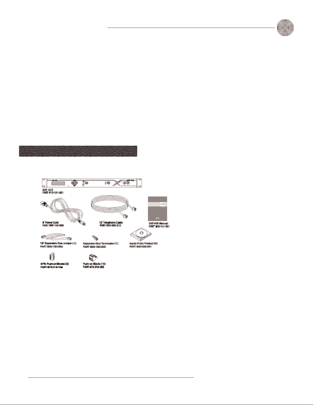
Ensure that the following items were received with your shipment:
Figure 1.1. Equipment included with XAP 400 unit
ClearOne is not responsible
!
You must make claims directly with
the carrier. Inspect your shipment
carefully for obvious signs of
damage. If the shipment appears to
be damaged, retain the original
boxes and packing material for
inspection by the carrier. Contact
your carrier immediately.
for product damage
incurred during shipment.
Technical Services Group ~ 1-800-283-5936 (USA) ~ 1-801-974-3760
Page 10
4
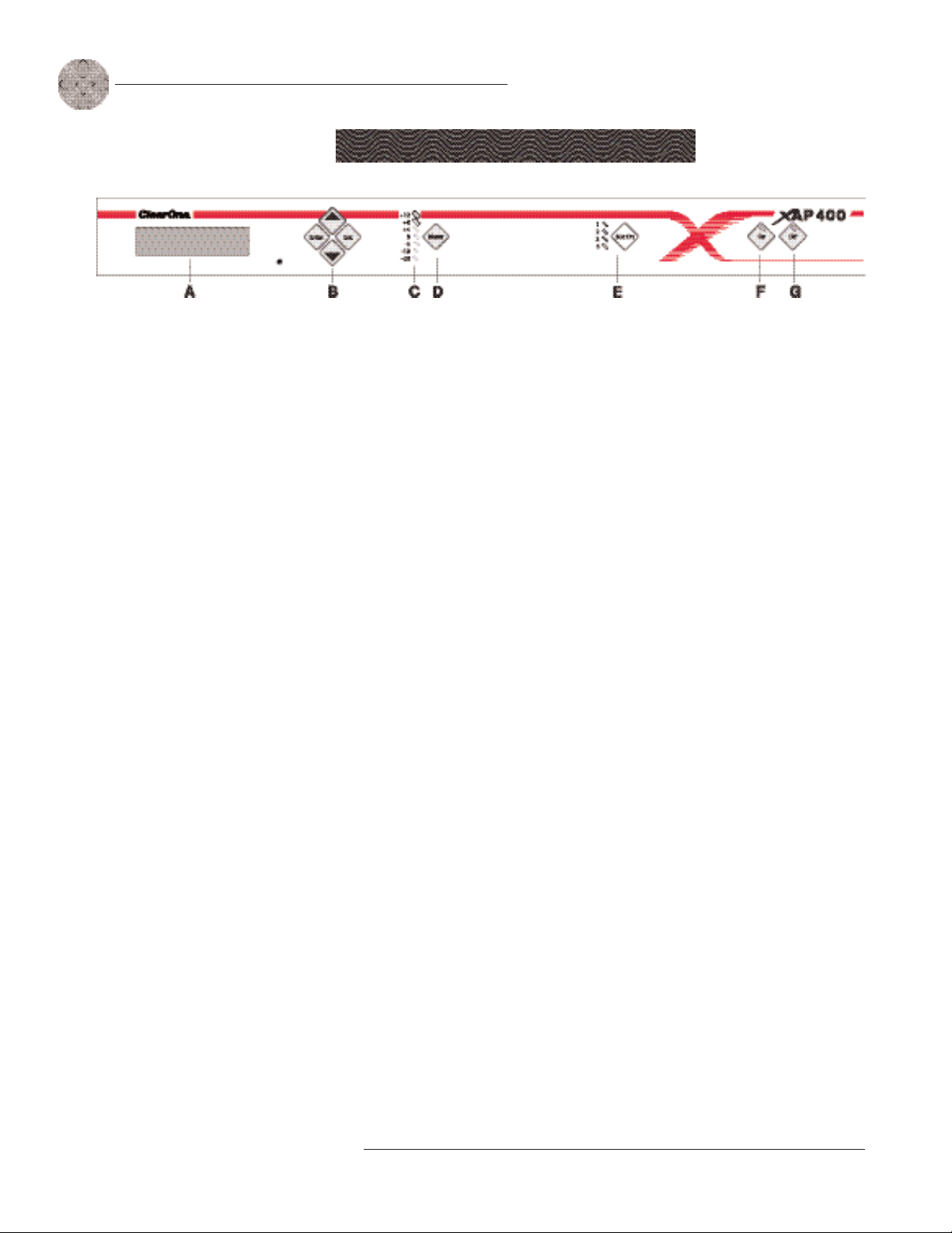
Figure 1.2. XAP 400 front-panel controls
Introduction ~ Controls and Connections
Controls and Connections
Front panel
The XAP 400 front-panel controls perform the following functions:
A. LCD. The LCD is used for numeric display of audio levels, gain readouts,
and limited set-up and programming functions. See page 13.
B. Enter//ESC. These buttons are used to navigate the XAP 400’s menu
system.
C. LED Meter. The LED bar meter is displays the audio level of a selected
input, output, or processing channel of the XAP 400. The audio level of
Output 8 is displayed by default. See page 16.
D. Meter. The Meter button takes you directly to the Meter branch of the XAP
400’s LCD programming tree. See page 16.
E. Mic On LED. These LEDs indicate microphone gate status.
F. On LED/button. The bicolor LED on the button illuminates green when the
hybrid is on. The On button connects the XAP 400 to the telephone line and
automatically adapts the hybrid to the line. Pressing and holding the On
button for more than a half-second while the hybrid is active will readapt
the hybrid to the telephone line.
G. Off LED/button. The bicolor LED on the button illuminates red when the
hybrid is off. The Off button disconnects the hybrid from the telephone line.
Technical Services Group ~ 1-800-283-5936 (USA) ~ 1-801-974-3760
Page 11
Introduction ~ Controls and Connections
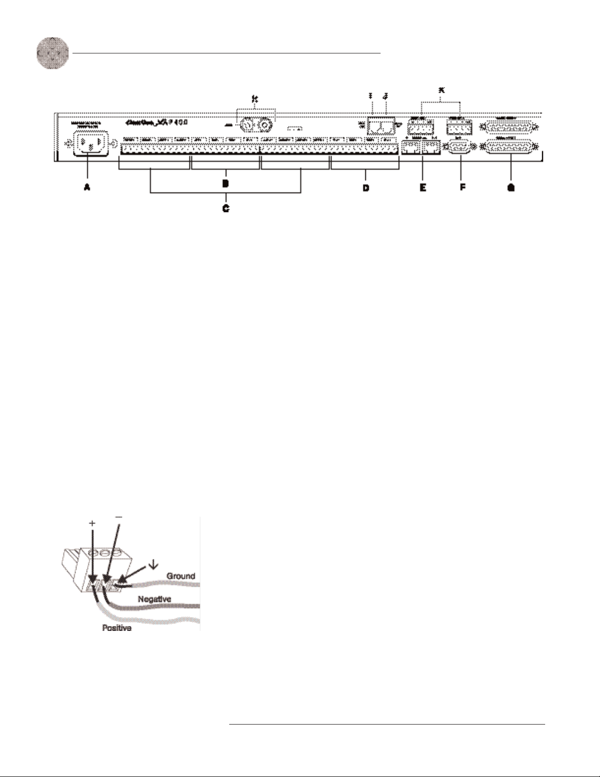
Rear panel
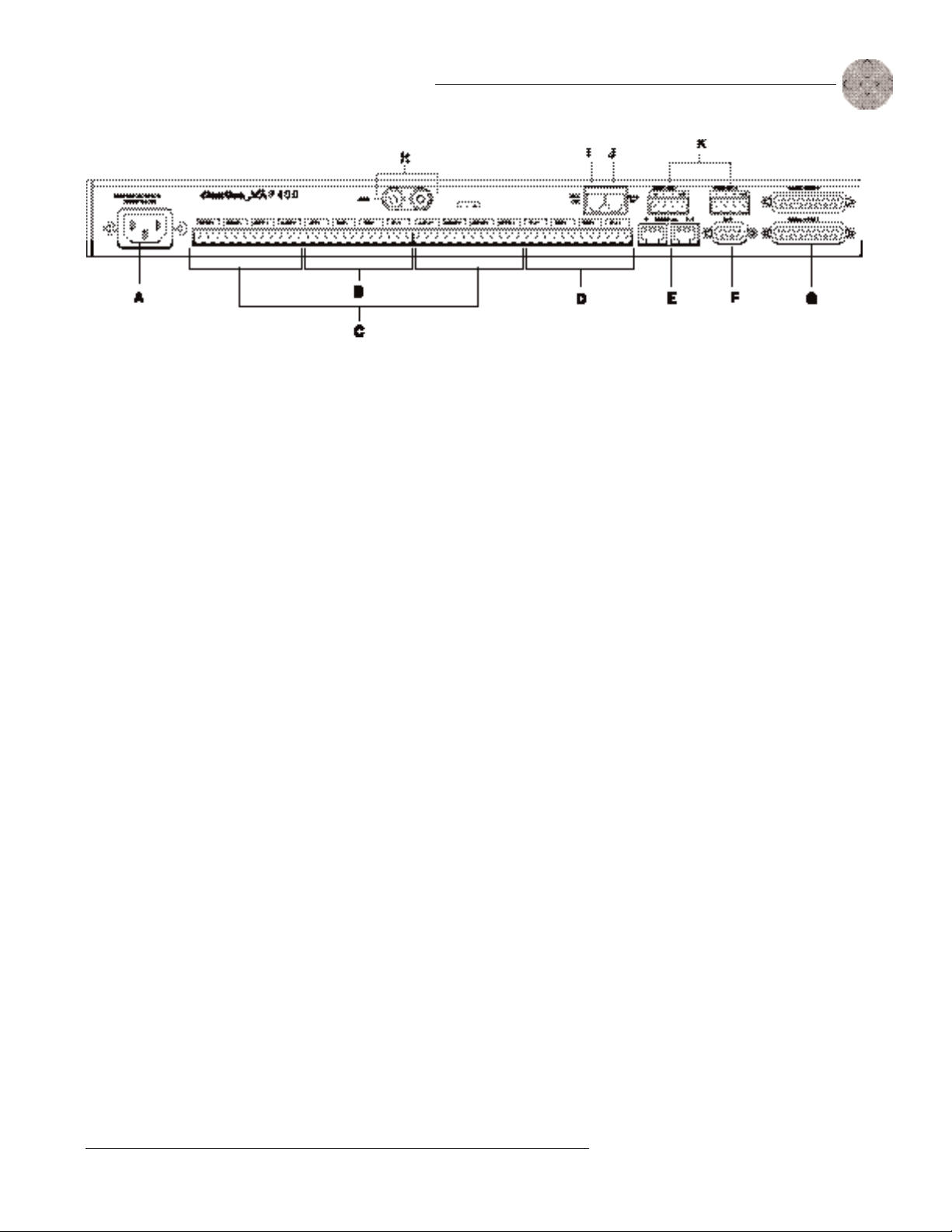
The XAP 400 rear-panel connectors perform the following functions:
A. Power. The AC power cord input is a IEC type connector allowing
100—240VAC, 50/60Hz.
B. Inputs 1—4. These Phoenix-type connection blocks are for mic and/or line
level inputs.
5
Figure 1.3. XAP 400 rear-panel connectors
C. Outputs 1—8. These Phoenix-type connection blocks are for line level
outputs that may be configured for any combination of gated and non-gated
inputs, as well as a mix of mic and line level inputs.
D. Inputs 5—8. These Phoenix-type connection blocks are for line level inputs.
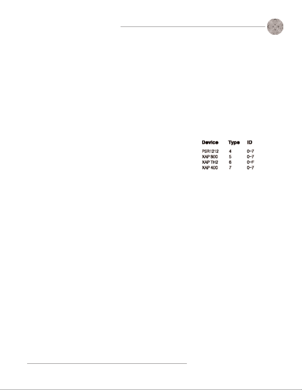
E. Expansion Bus In, Out. This RJ-45 connector is used to connect XAP
units. G-Ware is capable of accessing and controlling an expansion bus
network of up to eight XAP 400/800/PSR1212 units and 16 XAP TH2
units, where the total number of microphone inputs does not exceed 64. The
expansion bus supports a distance of up to 80 feet between each connected
XAP 400/800 or PSR1212.
F. RS-232. This female DB9 serial port connects the XAP 400 to a PC, modem,
or other custom remote controller. For serial commands, see page 104.
G. Control/Status Ports A and B. These two female DB25 connectors are for
general purpose input/output (GPIO) control of custom or unique control
devices. The control devices access the command set for the XAP 400 and
can be used for common functions such as volume control, muting, preset
changes, room combining, etc. Devices can be connected to either port.
For instructions on how to program the control and status pins, see the
GPIO section on page 87. The default settings allow control and status of
inputs, outputs, volume, and presets. These pins are active low. For pinout
and default information, see Appendix B.
Technical Services Group ~ 1-800-283-5936 (USA) ~ 1-801-974-3760
Page 12

6
Introduction ~ Networking
H. Speaker. This is a 10W power amp connector. A 4—16ž speaker can be
directly connected to the XAP 400, eliminating the need for an external
power amplifier.
I. Telco Line. This RJ-11 connector provides connection of a standard analog
telephone line to the hybrid.
J. Telco Set. This RJ-11 connector allows connection to a standard telephone
set. Tip and ring from the phone line are present at this connector when the
hybrid is off. Tip and ring from the phone line are not present at this point
when the hybrid is on.
K. RS-485 Remote Panel A/B Port. These four-pin Phoenix connector ports
allow you to control the XAP 400 with the ClearOne Control Panel or XAP
IR Remote.
Power is supplied through the RS-485 ports to the remote Control Panels
from the XAP 400. This power is limited to a total of 300mA at 15 volts
for each connector. Over-current protection is provided on the +15V pins to
prevent damage in the event of shorting. External power can be provided to
control devices when more current is required. See page 102 for maximum
cable run distances when using ClearOne Control Panels.
The latency or propagation
delay is <1ms.
Networking
Expansion bus
The digital mix-minus expansion bus (RJ-45 LAN) is used to connect up to eight
XAP 800/400s and 16 XAP TH2 units, where the total number of microphone
inputs does not exceed 64. The maximum distance between interconnected XAP
800/400 or PSR1212 units is 80 feet (24 meters). Connecting a XAP TH2 must not
increase the cable length between two PSR1212s, XAP 800s and/or XAP 400s
beyond 80 feet. ClearOne recommends that category five twisted-pair (10BaseT
LAN) cable be used.
The expansion bus (E-bus) allows audio routing between destinations on the
E-bus network. The E-bus contains 12 independent digital audio buses labeled O—Z
which can route mic or line level inputs in any combination across the E-bus
network. The O—Z buses are divided into two groups (O—R and S—Z) based on their
capabilities and default settings. The E-bus also contains four PA adapt/acoustic
echo cancellation reference buses, four global gating buses, and one control bus.
• O—R buses. These four audio buses are defaulted as the mic mix buses; they
can communicate the NOM count and mic mixing parameters across the
Technical Services Group ~ 1-800-283-5936 (USA) ~ 1-801-974-3760
Page 13

Introduction ~ Operational Requirements
network to other XAP 400s. All gated mics are routed to the 0-bus by default.
• S—Z buses. These eight buses are defaulted as auxiliary mix buses. They
are used to route auxiliary audio, such as from a CD player or VCR, to and
from other units on the network. These buses are also used as mic mix buses
when NOM count is not required.
• PA Adapt/Acoustic Echo Cancellation Reference buses. These buses
allow an input from a XAP 400 to reference an output on another linked
XAP 400/800. See PA Adapt and AEC Reference on page 33 for more
information.
• Global Gating Groups A-D buses. These mix-minus buses are defined as
microphone gating groups which support first-mic priority, maximum
number of mics, etc. and work across all linked XAP 400/800s. Unlike the
audio buses, they contain only mic status and gate parameters. See page 41
for more information about gating groups.
• Control bus. The control bus is an independent channel from the E-bus’s
audio channel; it uses a different pair of wires on the same E-bus cable. This
allows control information to pass even if the units are not using the audio
7
Operational Requirements
Power
The XAP 400 automatically accommodates voltage requirements of 100—240VAC,
50/60Hz, 15W.
Telephone line
The XAP 400 model operates on a standard analog telephone line and connects to
the telephone system with a standard RJ-11C modular jack. If you do not have an
RJ-11C jack where you want to install your XAP 400, call your telephone company
for installation.
The XAP 400 can be configured to meet compliance requirements of different
countries via the G-Ware software. See page 25.
Warning: The country code
!
unit operates properly when
connected to the telco network and
that it complies with the country’s
telco requirements. Changing this
code to a country other than the
intended country of operation might
cause the XAP 400 to be noncompliant.
must be set correctly in
G-Ware to ensure that the
Technical Services Group ~ 1-800-283-5936 (USA) ~ 1-801-974-3760
Page 14

8
Introduction ~ Operational Requirements
Equipment placement
The XAP 400 models are designed for installation in a standard 19-inch equipment
rack. You can also purchase side panels for desktop placement. See Appendix D for a
list of accessories.
Environmental
The XAP 400 can be safely operated in a room with varying temperatures between
32 °F/0 °C and 110 °F/43 °C.
Technical Services Group ~ 1-800-283-5936 (USA) ~ 1-801-974-3760
Page 15
CHAPTER 2 : I n s t a l l a t i o n
The XAP 400 is designed for easy installation and setup. All connections are made
through rear-panel connectors. This chapter provides instructions on installing the
units and making initial connections, creating an expansion bus (E-bus) network,
assigning device ID numbers, selecting the mixer mode, and using the LCD menu.
Hardware Setup
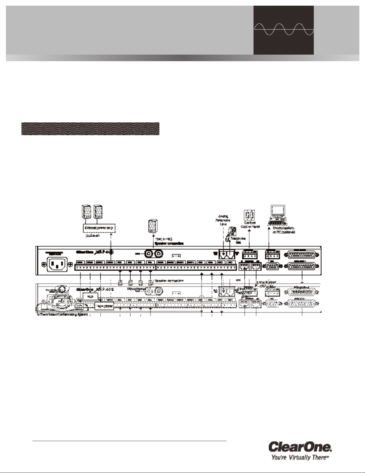
The diagram below illustrates the typical connections that are made for a single-unit
XAP 400 system. The default routing settings in the G-Ware Matrix Screen allow
the XAP 400 to work out of the box for this type of installation.
Technical Services Group ~ 1-800-283-5936 (USA) ~ 1-801-974-3760
Figure 2.1. XAP 400 installation diagram
Page 16
10
Figure 2.2. XAP 400 rear-panel connectors
Installation ~ Hardware Setup
To connect the unit
1. Place the unit in a standard 19-inch rack and attach it securely.
2. Connect your telephone line from the wall jack to the RJ-11C Line jack [I].
3. Plug your telephone set into the RJ-11C Set jack [J].
4. If you are using a custom controller for control and status, plug it into the
DB25 Control/Status A or B port [G].
The three terminals in
the Phoenix connector
correspond with the rearpanel audio contacts (from left to
right): + (positive), — (negative),
and
(ground).
Figure 2.3. Phoenix push-on connector
If you are using an external RS-232 controller, connect it to the
RS-232 port [F].
5. Wire the inputs and outputs to the XAP 400 using the provided three-
terminal Phoenix push-on connectors. These connectors are designed for
easy wiring; simply insert the desired wire into the appropriate connector
opening and tighten down the top screw.
• Inputs 1—4 [B] Mic or line level inputs
• Inputs 5—8 [D] Line level inputs only
• Outputs 1—8 [C] Line level outputs
6. If you are using a ClearOne Remote Panel, wire it to the RS-485 port [K]
using the provided four-terminal Phoenix push-on connectors.
7. Connect the speaker wire to the + (red) and — (black) binding post
connectors. A 4—16ž speaker can be directly connected to the XAP 400,
eliminating the need for an external power amplifier.
8. Plug in the XAP 400 to complete the installation. The power output [A] will
operate at any level between 100—240VAC and 50—60Hz.
If you are installing only one XAP 400 and are not connecting it to any other XAP
or PSR1212 units, you have completed the hardware installation.
Technical Services Group ~ 1-800-283-5936 (USA) ~ 1-801-974-3760
Page 17
Installation ~ Networking Units
Networking Units
Expansion bus connections
Using the Expansion Bus ports (RJ-45), you can connect up to eight XAP 800/400s
and 16 XAP TH2 units, where the total number of microphone inputs does not
exceed 64. Make connections between units in daisy-chain fashion using the short
RJ-45 jumper. If your units are further apart, use category five twisted-pair cable.
The maximum distance between interconnected XAP 800/400 or PSR1212
units is 80 feet (24 meters). Expansion bus cable length is calculated between
XAP 800s/400s and PSR1212s. The cable connecting a XAP TH2 to the network
is included in the cable length between the XAP 800 or XAP 400. For example, if
the cable from the XAP 400 to the XAP TH2 is 50 feet and the cable from the
XAP TH2 to the XAP 800 is 50 feet, then the total length between the XAP 400
and XAP 800 is 100 feet which is beyond the maximum 80-foot limit.
11
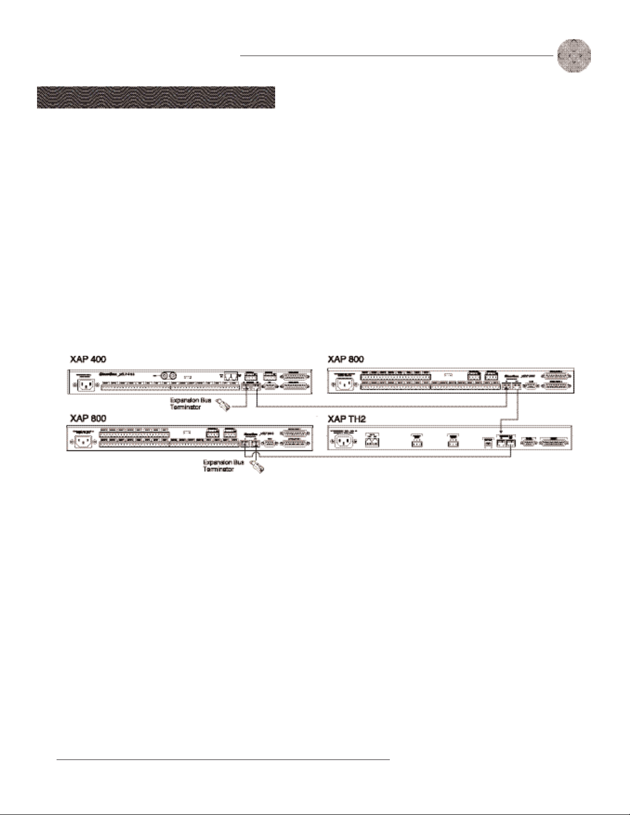
To create an expansion bus network
1. Plug the expansion bus terminator in the Expansion Bus In connector of
the first unit in the network.
2. Connect the RJ-45 jumper cable (or Cat 5 twisted pair cable) to the
Expansion Bus Out connector of the first unit in the network and
Expansion Bus In connector of the second unit. Continue connecting units
in the same fashion.
3. Plug the expansion bus terminator in the Expansion Bus Out connector on
the final unit to complete the network connections.
If the E-bus network is not connected properly, the front panel LEDs will
flash on the units that are physically connected to the network. To correct
the problem, check for broken connections and reconnect the expansion bus
cables.
Technical Services Group ~ 1-800-283-5936 (USA) ~ 1-801-974-3760
Figure 2.4. E-bus connection diagram
ClearOne recommends that
the first unit in your E-bus
network be a XAP 400 or
XAP 800 rather than a XAP TH2.
RS-232 system-wide control can be provided by any
unit in the network.
Page 18
12
Installation ~ Networking Units
If the same device ID is
assigned to more than one
unit on the E-Bus network,
the Meter LED “+12” will flash
red, the Mic LED “2” will flash
green, and the Off LED will flash
red on the affected units. To correct
the problem, change the device ID
on one of the conflicting units.
You can also use G-Ware
to select a mixer mode.
See page 25.
Device IDs
Once your expansion bus connections are made (and if you have more than one
XAP 400 at a site), you need to set up a unique expansion bus device ID number–a
network address–for each XAP 400 on the network. As shipped from the factory,
all XAP 400s default as device ID 0.
To assign device IDs
1.
Press the front-panel
System
2. Press
3. Press
Device ID is visible, press
in the Unit Properties window of G-Ware software see page 25.)
4. Repeat this process for each XAP 400 on the expansion bus network.
menu is visible.
Enter
, then scroll through the menu until
Enter
, then scroll through the eight (0—7) options. When the desired
Enter
button, then scroll through the menu until the
Device ID
Enter
to select it. (You can also set the Device ID
is visible.
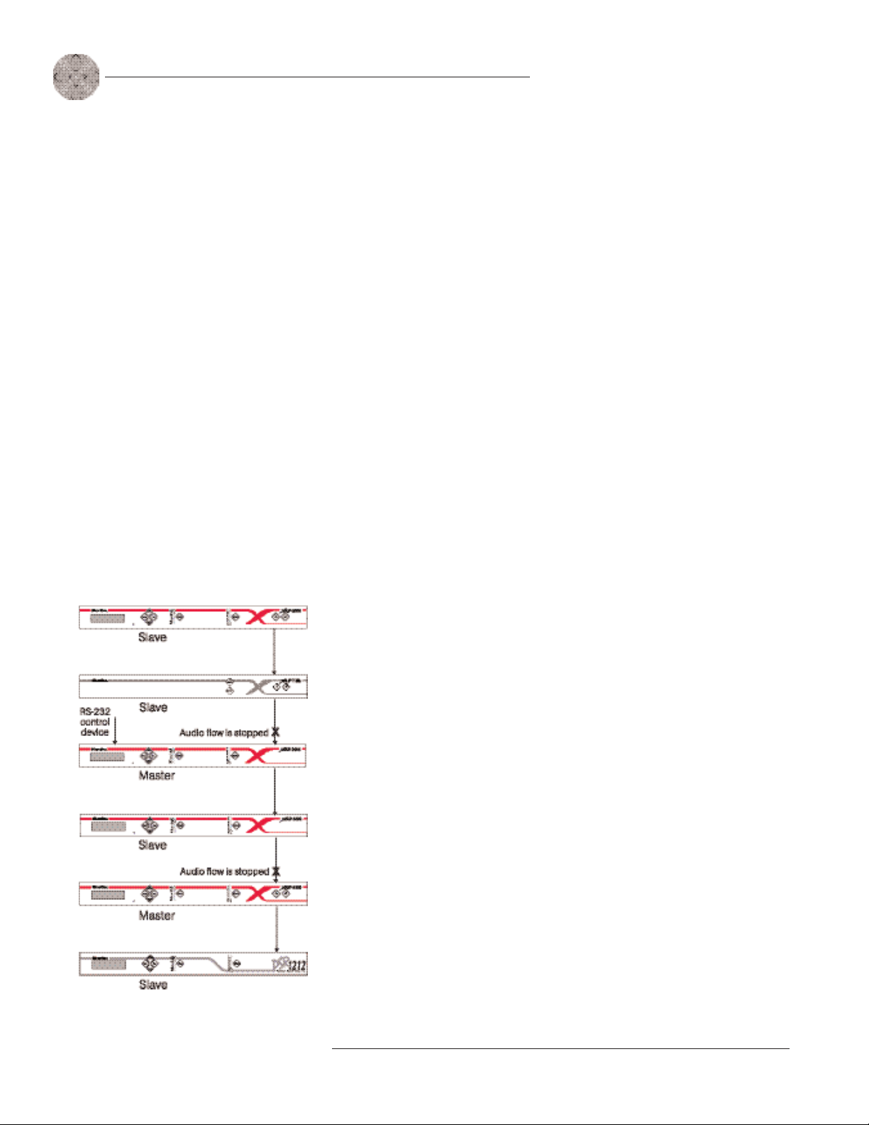
Mixer mode
There are two mixer mode settings: slave (default) and master. A master unit is not
required in a networked system and in most installations, all units will be slaves.
Master units ignore audio from upstream units. This prevents audio from being
received from units above the master unit in the network. However, global control of
the system is still maintained by whichever XAP 400/800 or PSR1212 unit is
connected to a control device through its RS-232 or RS-485 ports. Control is not
affected by master/slave designations.
Figure 2.5. E-bus network with master units
In Figure 2.5, the third unit in the network is a master. It prevents the audio
from the first and second units from being passed down the network chain.
Likewise the second master unit in the network will not pass on the audio from the
unit before it. The third unit provides system-wide control through a connection to
its RS-232 port.
To select a mixer mode
1. Press the front panel Enter button and scroll through the menu until System
menu is visible. Press Enter to select the menu.
2. Scroll through the System menu and select Mixer Mode.
3. Select the mixer setting you want to use.
Repeat for additional units.
Technical Services Group ~ 1-800-283-5936 (USA) ~ 1-801-974-3760
Page 19
Installation ~ LCD Programming
LCD Programming
13
The XAP 400’s front panel is intuitive to operate, thanks to its simple interface: a
2x16 character LCD, menu buttons, and a peak-level LED bar meter. Although most
of the XAP 400’s features are programmed with G-Ware software (see page 23), the
front panel can be used for simple adjustments and meter monitoring.
When power is applied to the XAP 400, the LCD panel will first read
INITIALIZING. If an error is displayed, contact technical support. When
initialization is complete, “XAP 400” is displayed on the top line and “Unit 0” is
displayed on the bottom line.
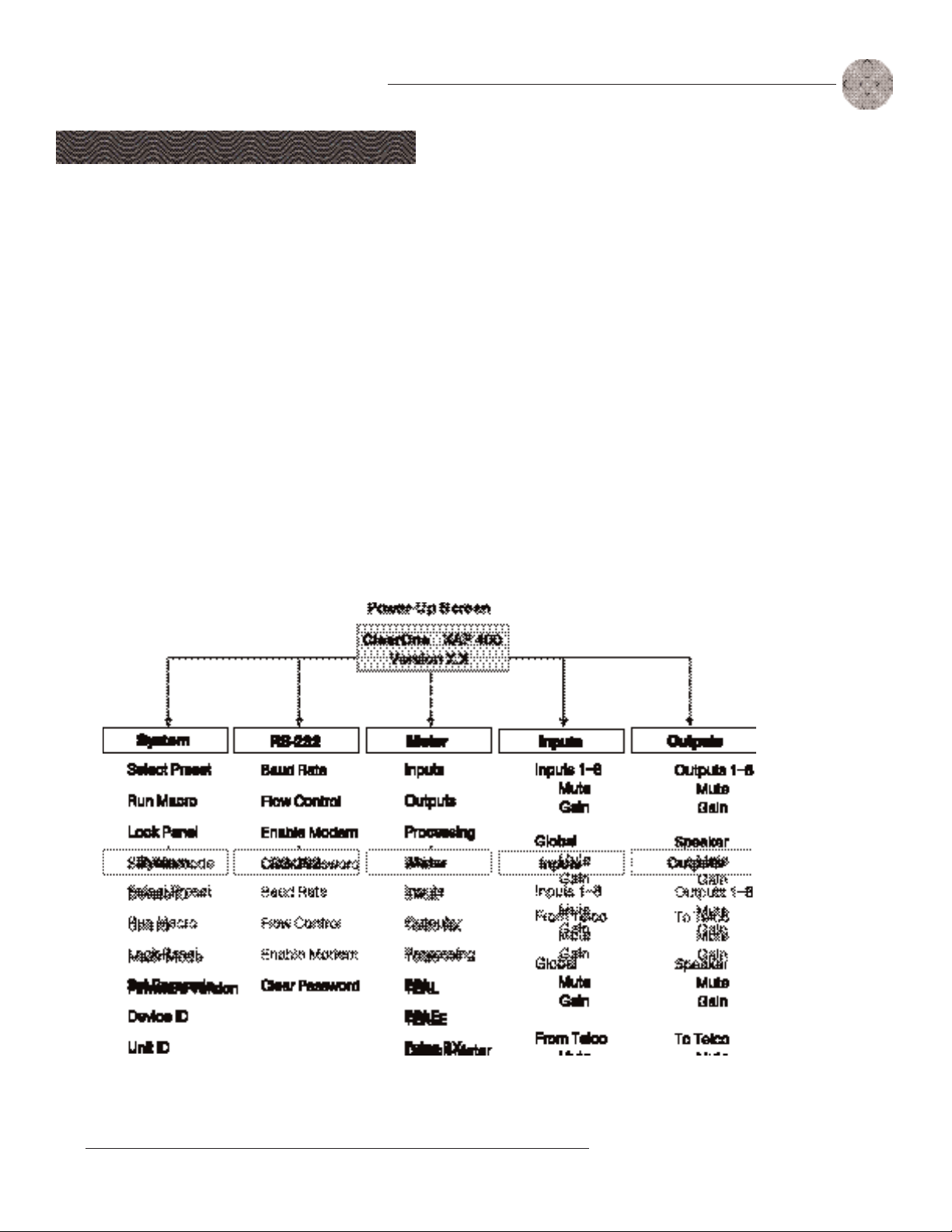
LCD menu tree
The menu tree features five main menus, each with submenus. These branches
typically end when an adjustable parameter or viewable value is reached. The
diagram below shows the LCD menu tree.
G-Ware software is
required to complete
system setup.
Pressing ESC at the top of
the tree does nothing.
Technical Services Group ~ 1-800-283-5936 (USA) ~ 1-801-974-3760
Figure 2.6. LCD menu tree
Page 20

14
Installation ~ LCD Programming
The five main menus are: System, RS-232, Meter, Inputs, and Outputs. All
submenu items are arranged under these menus. Use the Enter button to select items
and the and buttons to scroll through menus and submenus. When the last menu
item is reached, the display scrolls back to the beginning of the list. The Esc button
allows you to back out of the menus.
To adjust a parameter
1. Scroll to the parameter you want to adjust. Press Enter to select the
parameter. The parameter will flash when selected.
2. Adjust the value with the and buttons. As the value is adjusted, the
parameter is updated immediately.
3. To store the new value, press Enter. To discard the change and revert back
to the old value, press Esc.
If the Meter button is pressed while a parameter is being adjusted, the LCD
will switch to the Meter menu.
System menu
There are eight system-level parameters (see Figure 2.6): Select Preset, Run Macro,
Lock Panel, Set Passcode, Device ID, Mixer Mode, Unit ID, and Firmware Version.
The latter two are read only; they cannot be changed.
Select Preset
The Select Preset menu item allows for one of 32 preprogrammed presets to be
selected for XAP 400 use. To select a preset, scroll through the numbered presets
(1-32) until the desired preset is visible, then press Enter to run the preset.
Run Macro
The Run Macro menu item allows you to execute a macro. To select a macro, scroll
through the numbered macros (1-255) until the desired macro is visible, then press
Enter to run the macro.
Lock Panel
The front panel may be locked to prevent unauthorized adjustments to the XAP 400.
To lock the front panel, use the /buttons to select Lock Panel from the System
menu, and press Enter. Lock Panel selections are Off, On, or On at Timeout. Press
Enter to enable your selection.
Technical Services Group ~ 1-800-283-5936 (USA) ~ 1-801-974-3760
Page 21
Installation ~ LCD Programming
15
To unlock the front panel, attempt to adjust a parameter. The XAP 400 will
prompt for the passcode. Upon entering the fifth character (if entered correctly),
the front panel will unlock. The default passcode for all boxes is Enter.
Set Passcode
Once the XAP 400 is unlocked, the passcode may be changed. Before the XAP 400
will allow passcode changes, the new passcode must be entered, then re-entered to
validate the new passcode.
The front panel passcode can also be set (and reset) within G-Ware. See page
26 for more information.
Device ID
The XAP 400’s device ID is set from this menu. There are eight device ID selections
to choose from (0—7). Select the network position you want to use. Within a single
site, you must assign different device ID numbers for each XAP 400 unit. See Device
IDs, page 12.
Menu items can still be
scrolled through when the
panel is locked. However,
settings cannot be entered until the
panel is unlocked with the
appropriate passcode.
Unit ID
The Unit ID menu selection allows you to access the read-only address set at the
factory. This unique ID number identifies your particular XAP 400 unit and cannot
be changed.
Mixer Mode
This setting allows you to set to master or slave mode. See page 12 for details.
Firmware Version
This menu selection allows you to view which firmware version is being used. This
information cannot be changed.
RS-232 menu
There are four submenus under the RS-232 menu: Baud Rate, Flow Control, Enable
Modem, and Clear Password.
Baud Rate
This parameter allows you to set the XAP 400’s baud rate to 9.6kbps, 19.2kbps,
38.4kbps, or 57.6kbps. Default is 38.4kbps. Select the baud rate you want to use,
then press Enter.
Technical Services Group ~ 1-800-283-5936 (USA) ~ 1-801-974-3760
Page 22

16
Installation ~ LCD Programming
ClearOne recommends that
you leave Flow Control
enabled.
The modem initialization
string can only be set via
the MINIT serial
command (see page 130) or the
G-Ware software. It cannot be set
through the front panel LCD.
Flow Control (hardware)
The XAP 400 uses the RTS and CTS pins on the RS-232 port to regulate the
transmission and reception of data. You can enable or disable flow control on the
front panel of unit and select the flow control type in the Site Properties window of
G-Ware (see page 23). If you select On (default) from the front panel menu, select
Hardware as the flow control type in the Site Properties window. If you disable flow
control on the front panel, select None in the Site Properties window. When None is
selected, the XAP 400 ignores flow control, making the connected external control
device ensure that data is not lost. Software flow control (Xon/Xoff) is supported by
the XAP/PSR units and is only used with a pass-through device, such as a modem.
To avoid communication errors, ClearOne strongly recommends that you
connect all DB9 pins and enable flow control when connecting to a PC.
Enable Modem
This parameter configures the RS-232 port for connection of a modem. When On is
selected, the XAP 400 will send an initialization string to the modem on power-up
and require a password before data transfer is allowed through the port. When Off
(default) is selected, the password is disabled.
To use the XAP 400 with a modem
You can set the modem
password using the
MPASS serial command
(see page 131) or in G-Ware (see
page 26).
1. Match the baud rate of the modem to that of the XAP 400.
2. Turn off Serial Echo on the modem.
3. Turn off the modem’s response mode (e.g., no OK messages, ring, etc.).
4. Enable auto-answer on the modem.
Clear Password
This parameter allows you to erase the serial port (modem) password in case it has
been forgotten. Select Yes to keep the current password or No to erase it. Press
Enter to enable your selection.
Meter menu
There are 10 submenus under the Meter menu: Inputs, Outputs, Processing, ERL,
ERLE, Telco RX, Telco TX, TERL, TERLE, and Default Meter. The meter selection
determines what is shown on the front panel peak-level LED display. When the meter
is selected in the LCD menu tree, the LCD displays peak level indications as well.
Use the and buttons to select the Meter menu, then scroll through the options and
press Enter when you reach the desired option.
Technical Services Group ~ 1-800-283-5936 (USA) ~ 1-801-974-3760
Page 23

Installation ~ LCD Programming
Inputs
Select which input (1—4) you want to monitor on the LCD and LED display. Scroll to
the input, then press Enter. The meter displayed is the post-gain meter.
Outputs
This submenu allows you to choose which output (1—8) you want to monitor on the
LCD and LED display. Scroll to the output you want to monitor, then press Enter.
Processing
This submenu allows you to choose which processing channel (A-D) you want to
monitor on the LCD and LED display. Scroll to the output you want to monitor, then
press Enter.
ERL
This submenu allows monitoring of the ERL meters on the XAP 400. Select the
meter you want to monitor and press Enter.
17
ERLE
This submenu allows monitoring of the ERLE meters on the XAP 400. Select the
meter you want to monitor and press Enter.
Telco RX
This submenu allows you to monitor the Telco RX (Receive) meter on the XAP 400.
Press Enter to enable your selection.
Telco TX
This submenu allows you to monitor the Telco TX (Transmit) meter on the XAP 400.
Press Enter to enable your selection.
TERL
This submenu allows you to monitor the TERL meter on the XAP 400. Press Enter
to enable your selection.
Technical Services Group ~ 1-800-283-5936 (USA) ~ 1-801-974-3760
Page 24

18
Installation ~ LCD Programming
TERLE
This submenu allows you to monitor the TERLE meter on the XAP 400. Press Enter
to enable your selection.
Default Meter
This submenu determines what is displayed on the LED meter when a meter is not
specifically selected elsewhere in the Meter menu. The default is Output 8.
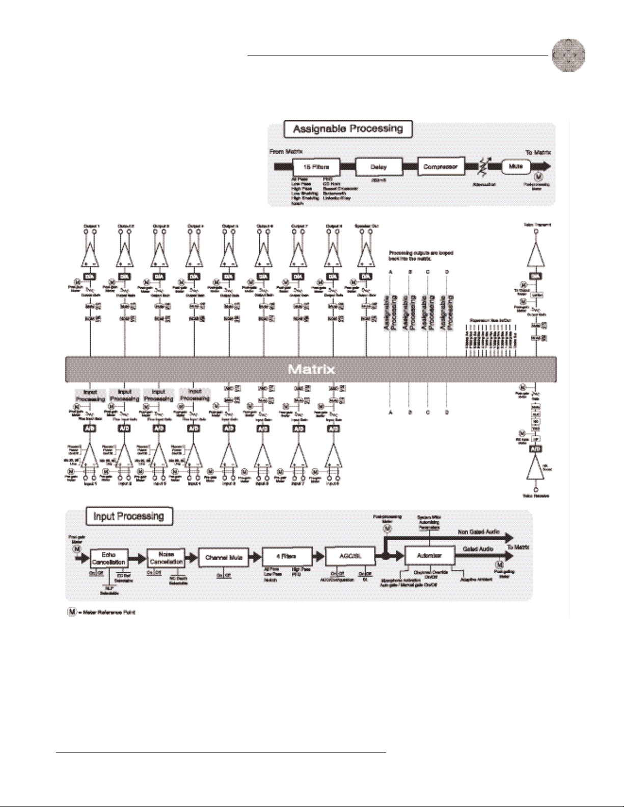
The Meter Reference Point diagram on following page shows where the meter
pick-up points ( ) are in the signal path through the XAP 400.
Inputs menu
There are two submenus under the Inputs menu: Mute and Gain. To access these
submenus you must first select the input. Choose from Inputs 1—8, Global, or From
Telco. Use the and buttons to select the Inputs menu, then scroll through the
options and press Enter when you reach the desired option.
Mute
This submenu allows you to turn mute on or off (default) for the selected input.
Gain
This submenu allows you to adjust the gain for the selected input. Use the and
buttons to increase or decrease gain.
Outputs menu
There are two submenus under the Outputs menu: Mute and Gain. To access these
submenus you must first select the output. Choose from Outputs 1—8, Speaker, or To
Telco. Use the and buttons to select the Outputs menu, then scroll through the
options and press Enter when you reach the desired option.
Mute
This submenu allows you to turn mute on or off (default) for the selected output.
Gain
This submenu allows you to adjust the gain for the selected output. Use the and
buttons to increase or decrease gain.
Technical Services Group ~ 1-800-283-5936 (USA) ~ 1-801-974-3760
Page 25
Installation ~ LCD programming
19
Technical Services Group ~ 1-800-283-5936 (USA) ~ 1-801-974-3760
Figure 2.7. Meter Reference Point diagram
Page 26

20
Technical Services Group ~ 1-800-283-5936 (USA) ~ 1-801-974-3760
Page 27

CHAPTER 3 : S y s t e m
Configuration
ClearOne’s G-Ware software provides an easy interface for configuring and
controlling your XAP 400. While some configuration can be done using the front
panel LCD menus, G-Ware is required to complete the custom configuration of your
audio conferencing system. If you are using the default settings, no configuration is
necessary.
This chapter describes how to install G-Ware, create a site, and set up the
telco portion of your system. It also describes all configurable parameters of your
system. These descriptions are designed to be used as a guide as you make
adjustments for your particular installation. It is not necessary to configure all
parameters.
G-Ware Requirements
G-Ware software must operate on computer equipment that meets the following
minimum requirements:
Windows 95 OSR2 64MB RAM
Windows 98 64MB RAM
Windows ME 64MB RAM
Windows NT 64MB RAM
Windows 2000 129MB RAM
Windows XP 256MB RAM
PII 200MHz or AMD Equal
1024x768 SVGA (16bit) high color
8M Video card
IE 4.0
20M HD space
RS-232 COM port
CD-ROM drive
Technical Services Group ~ 1-800-283-5936 (USA) ~ 1-801-974-3760
Page 28

22
System Configuration ~ Installing G-Ware
You can also access the
Disk Copy program from
the G-Ware install menu
which is located on the AV Products
CD (exefiles\gware\setup.exe).
Creating floppy disk copies
Depending upon the computer equipment you have available, you might need to
install G-Ware software from floppy disks rather than the included CD. To do this, a
Disk Copy program is provided in G-Ware that allows you to transfer G-Ware to
floppy disks. You will need a PC with a CD-ROM drive to make the transfer. After
installing G-Ware on the CD-ROM-equipped computer, you can access the Disk Copy
program in the following way:
• From the Windows Start menu, select Programs, ClearOne G-Ware, and
then Create Install Floppy Disks. Follow the onscreen prompts to complete
creation of the floppy disks.
Installing G-Ware
To install G-Ware
1. Boot the PC to the Windows operating system. Ensure that all other
programs or applications are closed. Insert the Audio and Video Products
CD into the CD-ROM drive.
To select an alternate
destination directory, click
Browse and use the Choose
Directory window to find the desired
location. Click OK to return to the
previous window.
Figure 3.1. Desktop icon
If the Autorun feature is enabled on the PC, the ClearOne Welcome window
opens. Click the Software tab and select G-Ware.
If the Autorun window does not open, open the Windows Start menu and
choose Run. Type “<drive>:\\gentner.exe” where <drive> is the letter of
the CD-ROM drive (e.g., D:\\gentner.exe).
2. At the G-Ware window, click Install G-Ware near the bottom of the window.
3. The InstallShield Wizard opens, and guides you through the Welcome and
License Agreement windows. At the Choose Destination Location window,
choose the directory where G-Ware will be installed. We recommend that
you use the default directory.
4. Click Next or Yes to move to proceed through the windows that follow or
No or Cancel to end the installation process.
5. Follow the onscreen instructions. You must restart your computer once
installation is complete.
The G-Ware Program Folder is now added to your Start menu. You can start
G-Ware through the Start menu or by double-clicking the desktop icon.
Technical Services Group ~ 1-800-283-5936 (USA) ~ 1-801-974-3760
Page 29
System Configuration ~ Site Setup
Site Setup
23
Creating a new site
New site files are created through the Site Properties window in G-Ware. A site file
contains all information about a particular installation including all unit settings and
properties. It also provides G-Ware with the necessary information to communicate
with the site hardware using your PC. Open G-Ware by double clicking the desktop
icon or by selecting G-Ware from the Start menu.
To create a new site
1. Open the Site Properties window by selecting New Site from the File menu
or by clicking the New Site button on the toolbar.
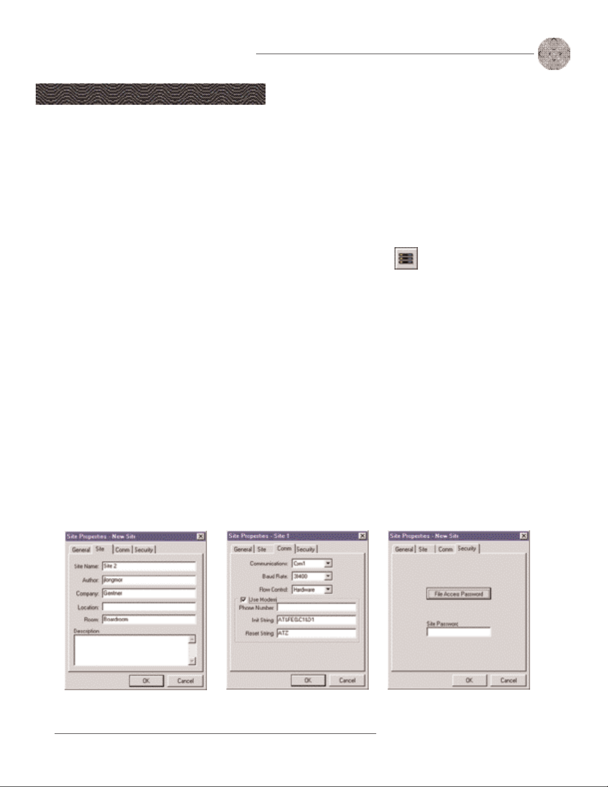
2. In the Site tab, enter the site name, author, company, location, room, and
description, using the Tab key or mouse to select each field.
3. Click the Comm tab. Select the COM port, baud rate, and flow control you
want to use. ClearOne recommends that you leave Flow Control set to
Hardware. The Software setting is not supported by XAP/PSR units and is
typically used with modems.
Whenever a mouse click is
indicated in this manual, it
refers to the left mouse
button unless otherwise stated.
Figure 3.2.
New Site button
You can enable flow
control using the XAP
front panel controls. See
page 16.
4. If you plan to use a modem, select Use Modem and enter the phone number,
initialization string, and reset string.
5. Click the Security tab. Enter the site password in the Site Password box.
Click File Access Password to create a password for the Site File.
Figure 3.3. Site Properties, Site tab
Figure 3.4. Site Properties, Comm tab
Figure 3.5. Site Properties, Security tab
Technical Services Group ~ 1-800-283-5936 (USA) ~ 1-801-974-3760
Page 30
24
Figure 3.6. Open
Site File button
System Configuration ~ Site Setup
Adding a XAP 400
You can add a XAP 400(s) to your site file by connecting to your site and using
G-Ware to automatically create icons for the detected units. Or, you can work offline
and manually add the unit(s) to the site file and connect to the site at a later time.
To open an existing site file, click the Open Site File button or select Open Site from
the File menu.
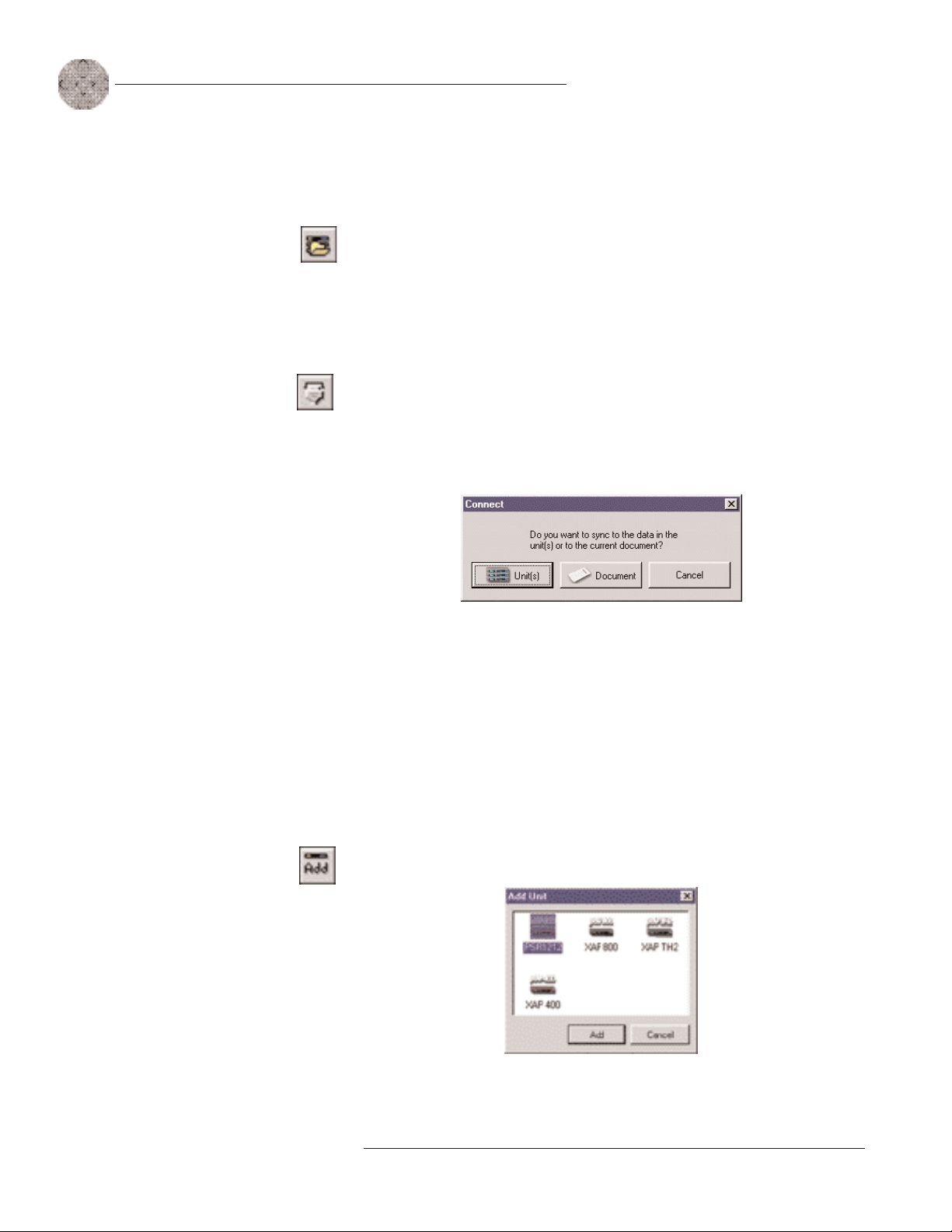
To auto-detect units
1. Click the Connect button on the G-Ware toolbar or select Connect from the
Connect Menu.
Figure 3.7.
Connect button
Figure 3.9. Add Unit
to Current Site
2. Choose Sync to Unit(s). G-Ware will automatically create icons for the new
units it detects on the network and place them in the Site pane. See Figure
3.11.
Figure 3.8. Connection choices
Note: When connecting to your site, you can choose to sync to Unit(s) or
Document. If you sync to the Unit(s), you will overwrite your G-Ware site file
with the current settings of the unit(s). If you sync to the Document, you will
overwrite the settings in your units with the settings you have saved in the site
file. Choosing to sync to Document will also create icons for any new units.
To manually add units
1. If you are working offline, click the Add button on the G-Ware toolbar. This
opens the Add Unit window.
Figure 3.10. Add Unit window
2. Select the XAP 400 icon and click Add.
Technical Services Group ~ 1-800-283-5936 (USA) ~ 1-801-974-3760
Page 31

System Configuration ~ Site Setup
Configuring Unit Properties
Using the Unit Properties window, you can configure the unit‘s communication and
security properties in addition to general unit properties such as name, type, and
country code. The Unit Properties window automatically opens when you manually
add a unit to the site. You can also right-click the unit icon in the site pane and click
Unit Properties.
To configure Unit Properties
1. Type a descriptive Unit Name in the space provided. The Unit Identification
and Firmware Version will be supplied by the unit when a connection is made.
2. If you have already established a connection with the site, the Device
ID will be assigned. Otherwise, select the Device ID that matches the ID you
assigned the unit via the front-panel LCD menu.
Device IDs ensure the software will sync up with the proper unit when there
are multiple XAP 400s on a network.
25
Figure 3.11. Unit icons in Site
Pane with Unit menu displayed
3. Select the Unit Type (default is slave). See page 12 for more information.
4. Select an input, output, or processing channel to be the Default Meter on
the front panel meter LED when a channel is not specifically selected.
5. Select the Meter Refresh Rate, which determines how quickly the XAP 400
updates meter information (default is 100ms; range is 50-1000ms).
6. Select the country where this product is being used from the Country Code list.
Warning: The country code must be set correctly to ensure that the unit
operates properly when connected to the telco network and complies with the
country’s telco requirements. Changing this code to a country other than the
intended country of operation might cause the XAP 400 to be non-compliant
and inoperable.
7. Click the Comm tab. The Baud Rate and Flow Control settings are supplied
by the unit when a connection is made. These settings are changed using the
Site Properties window (see page 23).
8. Set the Serial Echo (default On) and the Serial Mode (default Text). Serial
Echo echos back commands sent over the XAP 400 network. The serial mode
determines the format in which the commands return–text or binary. The
mode defaults to Binary when G-Ware is connected and to Text when dis-
connected. Contact technical support for instructions on using Binary mode.
Figure 3.12. Unit Properties, General tab
Figure 3.13. Unit Properties Comm tab
Technical Services Group ~ 1-800-283-5936 (USA) ~ 1-801-974-3760
Page 32

26
System Configuration ~ Site Setup
9. If a modem is connected to the XAP 400 unit, select Use Modem and enter
the initialization string. Click OK; the XAP 400 will initialize the modem.
10. Click the Security tab. Create a modem password. The password will be
required before control of the system is allowed. The default modem
password is a carriage return.
11. Preset/Macro Password enables you to password protect your individual
presets and macros. To create a password, click Preset/Macro Password.
Creating a Preset/Macro Password does not automatically lock all presets or
macros. Presets are locked in the Preset Configuration Mode. See page 60
for more information. Macros are locked in the Macro Editor. Presets and
Macros that are locked do not require the password to be run. However, the
password is required to make changes.
Figure 3.14. Unit Properties Security tab
12. Select the Front Panel Lock Mode.
• Unlock Panel leaves the front panel controls unlocked.
• Lock Panel locks the front panel immediately.
• Lock When Timeout locks the front panel after it is inactive for the
specified number of minutes. The range is from 0—15 minutes; 5
minutes is the default.
When locked, the front panel can be accessed only after entering the proper
passcode (sequence of button presses) or by unlocking the panel using
G-Ware.
13. To create a passcode for the front panel, click Clear to clear the default
sequence. Then click any sequence of the five front panel buttons. Your
choices will be displayed in the column on the right. When you are finished,
click OK to enable your selections.
You will need to repeat these steps for all XAP 400 units on your network.
Technical Services Group ~ 1-800-283-5936 (USA) ~ 1-801-974-3760
Page 33

System Configuration ~ G-Ware Screens
G-Ware Screens
G-Ware has three modes: Configuration, Preset, and Macro Recorder. Configuration
is used to configure the unit and is the default mode. The Preset and Macro modes
are discussed in Chapter 4: Advanced Configuration. You can switch between modes
by clicking on the corresponding toolbar button. The current mode is displayed on
the status bar.
There are two main configuration screens, the Flow Screen and the Matrix
Screen. All unit configuration and audio routing is accessed through these screens.
Flow Screen
27
Figure 3.15.
Configuration, Preset,
and Macro toolbar
buttons.
Figure 3.16. G-Ware Flow Screen
The G-Ware Flow Screen is the main access window for G-Ware’s features and
functions. Using the menus and toolbar at the top of the screen, you can access
general configuration windows. Unit specific configurations are accessed through the
buttons and labels on the Flow Screen itself. If you have multiple units, click on the
unit icon in the Site pane to access that particular unit’s Flow Screen.
The Flow Screen shows a detailed block diagram of the path of the audio
signal, presenting a graphical explanation of each stage of audio processing. Mic
and line inputs, outputs, telco receive and transmit, expansion buses, and
processing block configuration windows can all be accessed from this screen. The
XAP 400 Flow Screen has eight icons and buttons at the bottom of the Flow
Screen which open the following unit programs: Dial, Telco Config, Remote
Builder, Gating Control, Preset Mode, Macro Editor, Telco Meters, and GPIO
Builder.
Technical Services Group ~ 1-800-283-5936 (USA) ~ 1-801-974-3760
Page 34

28
Figure 3.17. Unit
shortcut menu
Figure 3.18. Inputs 1—4
shortcut menu
System Configuration ~ G-Ware Screens
Copying and pasting settings
G-Ware has shortcut menus which appear when you right-click a selection or
program window in G-Ware. These shortcut menus provide quick access to options
such as Print, Copy, and Paste that pertain only to that selection or screen region.
Using the Copy and Paste commands, you can copy and paste unit data such as a
single setting or the entire unit’s settings depending on which window you are in. For
example, if you are in the Inputs 1—4 window, using the shortcut menu will allow you
to copy and paste all of the input settings to other inputs. You can also use keyboard
shortcuts (Ctrl+C and Ctrl+V) to copy and paste settings. If you want to apply all
settings of a selected input to the rest of the inputs, select Apply to All.
Safety Mute
Figure 3.19.
Safety Mute
The Safety Mute feature in G-Ware enables you to mute all outputs if feedback or
audio problems occur during the configuration process. To use Safety Mute, click the
Safety Mute button on the G-Ware toolbar. Then find and correct the cause of the
problem. Click the Safety Mute button again to unmute the outputs.
Status bar
There are two status lights at the bottom of the G-Ware window representing the
unit and the site. The lights illuminate in various colors to indicate current status.
• Solid green. The item being configured is synchronized with the hardware.
• Solid red. The information being configured is saved in the software offline.
• Flashing red. The information is not saved or there is no hardware
connection.
• Solid yellow.
• Flashing yellow.
disconnect from the unit and reconnect. The Message Log will indicate the error
that occurred. See page 82 for more information.
Communications are pending.
There is a communication error. In this instance, you should
Technical Services Group ~ 1-800-283-5936 (USA) ~ 1-801-974-3760
Page 35

System Configuration ~ G-Ware Screens
Matrix Screen
The Matrix Screen is used to route audio to one or more destinations (outputs,
expansion bus, or processing). Any number of connections to outputs can be made in
the matrix. The Matrix Screen can also be used to access the Input, Output, Telco,
and Processing configuration windows by clicking on the buttons along the top and
left side of the routing matrix.
29
Figure 3.20. G-Ware Matrix Screen
A colored cell in the routing matrix marks the intersection or cross point of
the routing from input to output. The color of the cross point cell identifies the
input type: yellow = gated mic input, blue = non-gated mic input, and green = all
other inputs. The amount of attenuation is also shown in the cross point cell. Black
cell are restricted routing paths which prevent Telco, E-bus, and Processing
channels from being routed back to themselves.
The numbers and letters along the top and left side of the matrix show the
cross point coordinates. The input number or letter and the output number or
letter will be highlighted blue for the selected cross point.
All inputs and outputs are labeled to make it easier to identify channels.
Clicking on a label will open a labels window where you can change the channel
labels.
Figure 3.21. Inputs 1—4
Labels window
Technical Services Group ~ 1-800-283-5936 (USA) ~ 1-801-974-3760
Page 36

30
Figure 3.22. Matrix Routing
If you click the Clear
Matrix button, you will
clear all cross points in the
routing matrix.
System Configuration ~ Audio Routing
Audio Routing
Audio is routed in the Matrix Screen (see Figure 3.20 on previous page). To access
the Matrix Screen, click on the Matrix button on the Flow Screen. To return to the
Flow Screen, click the Flow Screen button.
The XAP 400 routing matrix has 25 possible input sources and 26 output
destinations, with level control at each cross point. Any input or combination of
inputs can be routed to any output or any combination of outputs. To clear the
matrix, click the Clear Matrix button located above the Routing Key.
To route an input, click in the routing matrix at the intersection between the
input and the output. A mic input can be designated as gated (yellow) or non-gated
(blue) by clicking repeatedly in the cross point. All other input cross points will be
colored green.
Expansion bus O—Z routing
Audio on any XAP unit in the E-bus network can be placed on the bus or taken off
the bus and routed to any destination within the unit. The XAP 400 has 12 digital
mix-minus buses:
Figure 3.23. Cross Point
shortcut menu
• O—R buses are defaulted as the mic mix buses and can communicate the
NOM count. Gated mics are default routed to the O-bus.
• S—Z buses are defaulted as the auxiliary mix buses. They are used to carry
auxiliary audio such as that from codecs and XAP TH2s. These buses are
used as mic mix buses when NOM count is not required.
Process A—D routing
There are four processing blocks on the XAP 400 (Processing A—D). With these
processing channels, you can apply filters, EQ, or other processing settings to an
input or a group of inputs which can then be routed to a single output or group of
outputs. See page 49 for more information on processing settings.
Cross point attenuation
Right-click on a cross point to open the Cross Point shortcut menu. Click Cross Point
Enter to open the Cross Point Attenuation Dial window.
Click the and buttons or click on the green indicator and rotate the dial
with the mouse to adjust the attenuation to the desired level (or enter the
numerical value directly in the window). The attenuation range is from 0 to -60dB.
Technical Services Group ~ 1-800-283-5936 (USA) ~ 1-801-974-3760
Page 37

System Configuration ~ Audio Routing
Click Close to exit. Note that the level control you have selected for the cross point
is indicated numerically in the matrix.
The Cross Point shortcut menu also allows you to copy and paste the current
Cross Point configuration, including attenuation, to other cross points. You can
copy a single cell or the entire matrix using the shortcut menu options. To copy
and paste a cross point to multiple cross points, press Ctrl+C to copy (or right-
mouse click). Then press Ctrl+V while holding down the left-mouse button and
drag the mouse over the cross points to which you want to copy the settings.
Matrix report
When you finish audio routing, you can print a detailed report of the matrix using
the Print Matrix option on the shortcut menu (see Figure 3.23).
The Print Matrix Report window displays all matrix routing and cross point
information. Click the Print icon button to print the report.
31
Figure 3.24. Cross Point window
Figure 3.25. Matrix Report window
Technical Services Group ~ 1-800-283-5936 (USA) ~ 1-801-974-3760
Page 38

32
System Configuration ~ Inputs and Outputs
Inputs and Outputs
Inputs 1—4 accept either
microphone (-55, -25dB)
or line level (0dB) inputs.
ClearOne recommends
using the XAP to mute
mics instead of using the
mute provided by some
microphones. External muting
devices limit the effectiveness of
Gentner D.E.C. To use the mute
button on a microphone, contact
ClearOne Technical Services.
Inputs 1—4
To open the Inputs 1—4 configuration window, click the Inputs 1—4 button on the
Flow Screen. The In 1—4 button on the Matrix Screen will also open this window.
These inputs are balanced and support both mic and line levels.
Figure 3.26. Inputs 1—4 configuration window
To select an input channel, click a blank area in the input pane. If you click
on the input label, a secondary window will open allowing you to rename the input.
The background color for the selected input channel will be light gray. The many
configurable properties of mic inputs are defined in this section.
Mute
Mute mutes the input channel. The light on the button illuminates red when Mute is
activated. Default is Off (unmuted).
AGC/SL
AGC/SL opens the Automatic Gain Control/Speech Leveler window. If Speech
Leveler or AGC is enabled, the light on the button illuminates green. Default for both
is off.
Technical Services Group ~ 1-800-283-5936 (USA) ~ 1-801-974-3760
Page 39

System Configuration ~ Inputs and Outputs
The
Speech Leveler
quickly equalizes the difference in speech levels in the room without bringing up noise.
If you use AGC with the Speech Leveler, set the AGC Response Time to >2 seconds.
AGC
adjusts softer and louder input audio to a consistent level that you select
(the target level). The target level range is from -30 to 20dB in 1dB steps. The
default target level is 0dB.
is a compander that is optimized for speech audio. It
33
Set the
want the AGC to apply to the signal. Maximum gain range is 0 to 18dB in 1dB
steps. The default value is 18dB. AGC occurs after the gain and filter settings in
the audio signal path.
The
the white box next to the meter to enable it.
The
response time. The Threshold determines the decibel level at which you want the
AGC to engage. Setting the threshold toward the higher end of the scale (near 0)
reduces background noise to a greater degree. The Response Time is measured in
milliseconds. Target Level and Threshold are both RMS.
Target Level
Active Gain
Response Time
first, then apply the amount of maximum gain that you
meter reflects the overall gain at any given moment. Click
adjustment determines the total AGC engage/disengage
P Pwr (Phantom Power)
Phantom Power toggles the phantom power on and off. Phantom power is an
auxiliary power source to power certain types of microphones. The XAP 400’s
phantom power voltage is 24VDC. Default is On.
Figure 3.27. AGC/Speech Leveler window
All meters in G-Ware are
peak meters. The target
level and threshold
controls in the AGC/SL window
reflect RMS values.
AEC
AEC opens the Acoustic Echo Canceller window. To enable the acoustic echo
canceller, click
expansion bus references, four virtual references, or Speaker output can be selected.
PA Adapt and AEC Reference
If you select an
Bus Ref window opens so you can identify which expansion bus output you want to
use as the AEC’s reference. You can also open this window from the toolbar.
Enabled
expansion bus reference
Technical Services Group ~ 1-800-283-5936 (USA) ~ 1-801-974-3760
, then select the reference. Any one of the eight outputs, four
, the Define PA Adapt/AEC Expansion
Figure 3.28. Define PA/AEC
window and toolbar button
Figure 3.29. AEC window
Page 40

34
System Configuration ~ Inputs and Outputs
Figure 3.30.
Virtual Reference
toolbar button
If you select a
will open. You can also open this window from the G-Ware toolbar.
Figure 3.31. Virtual Reference window.
virtual echo cancellation reference
, the Virtual Reference window
Use this window to select which signals will be used by the four Virtual
Reference points. The routing matrix portion of this window can not be edited.
Virtual references are used when you need to reference multiple outputs. For
example, if you have stereo outputs (L, R) near a block of mics, you would want
the mics’ echo canceller to reference both the left and right outputs. By using a
virtual reference, the echo canceller will be able to reference both signals. This
means you don’t need to use a dedicated output to combine signals.
Or, you may have mics routed to the PA output but you don’t want the echo
canceller to reference this audio. By using a virtual reference, the echo canceller
can sample all signals routed to the PA output, minus the mic signals.
To create a virtual reference
1. Select the input signals you want included in each virtual reference by
clicking the cross points.
2. Because AEC requires a physical output reference to track output gain
changes, you need to select an output reference for AEC to function properly
with a virtual reference. Use the lists at the bottom of the window to select
which output you want AEC to use to track gain changes.
3. Click Close to exit the window.
Technical Services Group ~ 1-800-283-5936 (USA) ~ 1-801-974-3760
Page 41

System Configuration ~ Inputs and Outputs
Non-linear Processing (NLP)
The Non-linear Processing (NLP) feature increases the power of echo cancellation
for difficult acoustical environments. NLP features four settings: Soft (6dB),
Medium (12dB), Aggressive (18dB), and Off. Use NLP with care; corresponding
trade-offs can include suppression and half-duplex operation. Default is Soft.
Meters
The Echo Return Loss (ERL) meter on the Acoustic Echo Canceller window shows
the coupling between the reference signal and the input to the echo canceller–the
ratio of the two levels. It is an average meter that updates only when a signal is
present.
The Echo Return Loss Enhancement (ERLE) meter shows the loss through the
echo cancellation and non-linear processing chain–the ratio of the two levels. It is
an average meter that updates only when a signal is present.
The Total Echo Reduction meter shows the total ERL and ERLE reduction, in
decibels. It is an average meter that updates only when a signal is present.
35
NC
The NC button on the selected input in the Inputs 1—4 window opens the Noise
Canceller window. The noise canceller reduces ambient noise in the signal with no
noticeable degradation in signal quality.
To use noise cancellation, click Enable Noise Canceller, then adjust the
Cancellation Depth to the setting which provides the best combination of low noise
and maximum speech clarity. The attenuation depth can be set in 1dB increments
from 6dB to 15dB. Default is 6dB.
The noise canceller default is Off. When noise cancellation is enabled, the
light on the NC button illuminates green.
Filters
The Filter button on the selected input in the Inputs 1—4 window opens the Filter
Graph setup window. Each mic/line input has four configurable filters that can be
used as filters or equalizers. By default, they are not enabled and the filter types are
not defined. Below is a description of each feature in the window.
Figure 3.32. Noise Canceller window
Active Filter
Active Filter selects among filters on the graph. Note that no filters exist until you
click Add Filter (see Figure 3.33) to add filters to the graph.
Technical Services Group ~ 1-800-283-5936 (USA) ~ 1-801-974-3760
Page 42

36
System configuration ~ Inputs and Outputs
Figure 3.33. Inputs 1-4 Filters window
Type
Use the Type list to select from the following input filters: All Pass, High Pass, Low
Pass, Notch, and PEQ. G-Ware features other filters which are configured in the
Processing section of the software (see page 49).
• All Pass. Frequency range is 20Hz to 20kHz with resolution to 1Hz or four
places (whichever is larger).
• High Pass. Selectable frequency cutoff is 20Hz to 20kHz, in 1Hz
increments. Rolloff is 12dB/octave. Level is fixed at 0dB.
• Low Pass. Selectable frequency cutoff is 20Hz to 20kHz in 1Hz increments.
Rolloff is 12dB/octave. Level is fixed at 0dB.
• Notch. Center frequency range is 20Hz to 20kHz with resolution to 1Hz or
four places (whichever is larger). Bandwidth is from .05 to 5 octaves in .01
octave increments. Level is fixed at -80dB.
• PEQ (parametric equalizer). Center frequency range is 20Hz to 20kHz
with resolution to 1Hz or 4 places (whichever is larger). Bandwidth is .05 to
5 octaves in .01 octave increments. Level range is -15 to +15dB in 0.5dB
increments.
Frequency. Use Frequency to select the center frequency (in Hertz) for the filter
you are configuring. Range is from 20Hz to 20kHz. Default is 1kHz.
Gain. Gain adjusts the gain value from -18 to 18dB, in .5dB steps. Default is 0dB.
Q, or Quality factor. Q, or Quality factor, selects the ratio of the center frequency
divided by the bandwidth. Q reflects an inverse relationship to the bandwidth, and
adjusts from .02:1 to 40:1 on the XAP 400.
Technical Services Group ~ 1-800-283-5936 (USA) ~ 1-801-974-3760
Page 43

System Configuration ~ Inputs and Outputs
Bandwidth. Bandwidth establishes the difference between the upper and lower
points of a filter’s audio passband.
Bypass. The Bypass box, when selected, bypasses the selected filter.
Phase. Phase generates–on the graph–the phase relationship of the graphed
frequency response.
Bypass All. Bypass All bypasses all filters.
Add Filter. Add Filter adds a filter to the graph, centered at 1kHz and 0dB.
Remove Filter. Remove Filter removes the selected node from the graph.
Table View
37
Figure 3.34. Filter Graph window
Table View toggles between the Graph and the Table views of the Inputs 1-4 Filter
window. The Table view displays the selected filter settings in table format. You can
configure filters from this view as well as in the graph view.
To configure filters
1. In either the graph or table view, select the filter type from the Type list.
Note that the configurable filter parameters displayed depend on the
selected filter type.
2. Click Add Filter to add a filter to the graph or table.
3. Configure filter parameters using the previously described lists. If you are
using the graph view, you can click on the node and drag it to the location
you desire on the graph.
4. Click Close to exit.
Technical Services Group ~ 1-800-283-5936 (USA) ~ 1-801-974-3760
Page 44

38
System Configuration ~ Inputs and Outputs
Gate
The XAP 400 has unique gating parameters which control microphone activation.
The Gate button on the selected input in Inputs 1—4 window opens the Gate
configuration window where you can establish the gating parameters for the input.
Activation
There are three mic activation settings: Auto Gate, Manual On, and Manual Off.
• Auto Gate determines mic gating based on the input level and gating settings
for the gating group the input is assigned to. It contributes to and is affected
by all gating group settings such as NOM, chairman override, etc.
Figure 3.35. Gate window
• Manual On activates a mic, provided it does not exceed max NOM
requirements of the gating group that the input is assigned to. It is included in
the NOM count.
• Manual Off deactivates a mic.
Chairman Override
Chairman Override provides gating priority for this mic input over any other mic
input within the same gating control (mixer) groups. When a mic with Chairman
Override enabled gates on, all mics which don’t have Chairman Override enabled will
gate off. Default is off.
Adaptive Ambient
Adaptive Ambient adjusts the ambient reference level as noise and room conditions
change. When adaptive ambient is on, the mic channel monitors the ambient noise
level on the input and adjusts the ambient level reference automatically. This means
that the gate threshold level automatically increases or decreases based on back-
ground noise. If Adaptive Ambient is turned off, the input will use the fixed ambient
level specified in the Ambient Level box as its gating reference. Default is on.
PA Adaptive Mode
PA Adaptive Mode uses loudspeaker audio level on a specified output as the new
ambient level when audio is present at the power amplifier. This prevents
loudspeaker audio from gating on the mic, while still allowing people in the room to
gate on microphones as they speak–provided that their voices are louder than the
loudspeaker audio. For example, you might decide to play background music from a
CD player during a presentation. PA Adapt Mode allows you to use the output routed
from the CD player as the ambient reference to prevent the CD player’s audio from
gating on microphones. An output must be specified as the PA Adaptive Reference
(this is the same as the AEC reference) for each mic in the system. Default is on.
Technical Services Group ~ 1-800-283-5936 (USA) ~ 1-801-974-3760
Page 45

System Configuration ~ Inputs and Outputs
Figure 3.36. XAP 400 automixing gate functions
Gate Ratio
39
Gate Ratio specifies how much louder the audio level must be above the ambient
level before the channel gates on. The gate ratio range is from 0 to 50dB. Default is
15dB.
Hold Time
Hold Time determines how long the channel stays gated on after the audio is below
the threshold. The hold time range is from .1 to 8.0 seconds. Default is .3 seconds.
Off Attenuation
Off Attenuation sets the amount of level reduction applied to a channel when it is
gated off. The range is from 0 to 50dB. Default is 12dB.
Ambient Level
Ambient Level is available only if the Adaptive Ambient feature isn’t enabled. Use
Ambient Level if you want to specify a fixed reference point rather than one that
adjusts for background noise. The range is from -80 to 0dB. Default is Off.
Decay Rate
Decay Rate determines how fast a channel gates off after the hold time expires.
Default is Medium.
Technical Services Group ~ 1-800-283-5936 (USA) ~ 1-801-974-3760
Page 46

40
System Configuration ~ Inputs and Outputs
The PA Adapt Reference
and AEC Reference are the
same for each channel. If
you change the PA Adapt Reference
for a channel, you will also make
the same change to that channel’s
AEC Reference.
Figure 3.38.
Virtual Reference
toolbar button
PA Adapt and AEC Reference
When using either the PA Adaptive mode (see page 38) or Acoustic Echo
Cancellation (see page 33), the output that carries this information, i.e. the reference
output, must be defined. Select the PA Adapt and AEC Reference from the drop-
down list. Any one of the eight outputs, four expansion bus references, four virtual
references, or Speaker output can be selected.
If you select an
Expansion Bus Ref window opens so you can identify which expansion bus output you
want to use as the PA reference. You can also open this window from the toolbar.
Figure 3.37. PA Adapt/AEC
window and toolbar button
If you select a
Reference window will open. This window allows you to select which signals will be
used by the four virtual reference points. Virtual references are used when you
need to reference multiple outputs. The routing matrix portion of this window can
not be edited. You can also open this window from the G-Ware toolbar.
expansion bus reference
virtual echo cancellation reference point
, the Define PA Adapt/AEC
, the Virtual
Figure 3.39. Virtual Reference window.
Technical Services Group ~ 1-800-283-5936 (USA) ~ 1-801-974-3760
Page 47

System Configuration ~ Inputs and Outputs
Gating Group Select
In addition to specifying gating characteristics for each mic input, you can assign the
inputs to a gating group for greater flexibility and control. When inputs are
assigned to a gating group, the gating information from the inputs is used to
control how the entire mixer behaves.
The XAP 400 features four internal gating groups (Internal 1—4) and four
global gating groups across the expansion bus (Global A—D). Microphones can only
be used in one gating group at a time. If an input is not assigned to a gating
group, that mic’s gate properties are independent and have no effect on any other
gating group. When gating groups span two or more units (global gating groups),
the settings must be the same for each unit attached to the global gating group.
Mic inputs are routed to Global Group A by default.
To assign a gating group
Select the Internal or Global group the mic input will belong to or select
•
None.
41
Figure 3.40. Gating
Group Select pane
To configure gating group settings
1. Click the Gating Control button on the toolbar. This opens the Gating
Controls window.
Figure 3.42. Gating Controls window
2. Select the Max # of Mics (default is 4).
This sets the maximum number of microphones that can be gated on at any
one time within a gating group. For internal groups, the maximum number
of mics can be from 1 to 4. For global groups the maximum number of mics
will vary depending on how many mic inputs are assigned to the gating
group (up to 64). You can also select All for the global groups–which
means all mics could gate on.
Figure 3.41. Gating Control button
Technical Services Group ~ 1-800-283-5936 (USA) ~ 1-801-974-3760
Page 48

42
System Configuration ~ Inputs and Outputs
3. Leave 1st Mic Priority selected (default) to enable this feature; otherwise,
clear the selection to disable it. ClearOne recommends leaving this setting on.
This setting helps maintain maximum audio intelligibility by allowing only
one mic to gate on to a participant’s voice. 1st Mic Priority allows more
than one microphone to be activated at same time–it simply restricts mics
from gating on to the same audio source. It does this by determining the
audio level received by all mics when the first mic is gated on. This audio
level is then used as the ambient level for the gating group. If this feature is
disabled, usually two or more microphones gate on when only one person
speaks.
4. Select last-mic operation from the Last Mic Mode list. There are two
options for Internal groups: Last On and Off. If you are configuring Global
groups, you can select from the mic inputs assigned to the Global group in
addition to Last On and Off.
Last On leaves the mic that was activated last full on until another mic input
is gated on. The Input setting allows you to select which mic input the XAP
400 leave on when all mics gate off. If Off is selected, all mics will gate off
when no audio is present. It is preferable in most applications to leave a mic
on so the remote participants don’t think they have lost their audio
connection. Off is typically only used when you are conferencing multiple
sites and need to reduce background noise.
Figure 3.43. Gain
adjustment
5. Click the Gating Group label to change the group names.
Gain
The Coarse and Fine sliders on the selected input on the Inputs 1—4 window are used
to match the level settings for microphone inputs and to adjust input volume level.
• Set the Coarse gain to 55dB for a mic input, 25dB for active equipment that
requires an input between mic and line level, or 0dB for a line level input.
• Use the Fine gain slider to adjust input volume level.
level directly in the 0.0dB box.
Min/Max limits
Use the yellow and blue upper and lower limit arrows on the Fine gain scale to
create minimum and maximum gain level limits. These limits only apply when using
relative gain commands; absolute gain commands can exceed the min and max
limits. Min/Max limits apply to all serially connected control devices and prevent
users from adjusting levels beyond the min/max levels, provided relative gain
commands are used.
You can also enter the
Technical Services Group ~ 1-800-283-5936 (USA) ~ 1-801-974-3760
Page 49

System Configuration ~ Inputs and Outputs
Optimizing input gain structure
How you adjust an input’s gain directly affects sound quality. The optimal input gain
setting is one which is adjusted as high as possible above the noise floor without
introducing clipping. Clipping can cause distortion which can damage amplifiers and
loudspeakers.
To adjust the input level properly, place a signal on the input at the maximum
level it will generate. Adjust the input gain until the peak level of the input, as
shown on the Input meter, just begins to enter the red (clipping) zone, then reduce
the gain slightly until peaks no longer climb into the red zone. This setting will
ensure that the XAP 400 maximizes the signal-to-noise ratio without clipping the
signal.
Meters
There are four meters on each mic/line input to assist with setup and level control.
Select the meter check box to enable the meter. All input meters are peak-level.
43
Figure 3.44 Meter locations in the Inputs 1—4 signal path
Pre Gain
Pre Gain meter indicates the input’s level before gain adjustments. Meter range is
from -85 to -35dB when 55dB gain is selected; -55 to -5dB when 25dB gain is
selected; and -65 to 20dB when 0dB gain is selected.
Post Gain
Post Gain meter shows the input’s level after gain adjustments have been made.
Meter range is from -30 to +20dB.
Post Processing
Post Processing meter indicates the level at the gating point after the signal has
passed through input processing. It reflects the post-AGC signal. Meter range is
from -30 to +20dB.
Post Gating
Post Gating meter shows audio level after it has passed through the gating
parameters. Meter range is from -30 to +20dB.
Figure 3.45. Mic
input meters
Technical Services Group ~ 1-800-283-5936 (USA) ~ 1-801-974-3760
Page 50

44
System Configuration ~ Inputs and Outputs
Inputs 5—8
The XAP 400 supports 4 line level only inputs for auxiliary audio sources such as
video codecs and CD players. To open the Inputs 5—8 configuration window, click the
Inputs 5—8 button on the Flow Screen. The In 5—8 button on the Matrix Screen will
also open this window. These non-gated inputs are balanced. The nominal input level
is 0dBu.
Figure 3.46. Input 5-8 Configuration window
To select an input channel, click a blank area in the input pane. If you click
on the input label, a secondary window will open allowing you to rename the input.
The background color for the selected input channel will be light gray. The
configurable properties of these inputs are defined in this section.
Mute
Mute mutes the input channel. The light on the button illuminates red when Mute is
activated. Default is off (unmuted).
AGC
AGC opens the AGC window. The AGC window has the same parameters as the
AGC/SL window with the exception of Enable Speech Leveler. See page 32. The
button light illuminates green when AGC is enabled.
Technical Services Group ~ 1-800-283-5936 (USA) ~ 1-801-974-3760
Page 51

System Configuration ~ Inputs and Outputs
Gain
The Gain slider on the selected input in the Inputs 5—8 window is used to adjust input
volume level.
45
• Use the Gain slider to adjust input volume level.
directly in the decibel box below the gain scale.
Min/Max limits
Use the yellow and blue upper and lower limit arrows on the Gain scale to create
minimum and maximum gain level limits. These limits only apply when using relative
gain commands; absolute gain commands can exceed the min and max limits.
Min/Max limits apply to all serially connected control devices and prevent users from
adjusting levels beyond the min/max levels, provided relative gain commands are
used.
You can also enter the level
Optimizing input gain structure
How you adjust an input’s gain directly affects sound quality. The optimal input gain
setting is one which is adjusted as high as possible above the noise floor without
introducing clipping. Clipping can cause distortion which can damage amplifiers and
loudspeakers.
To adjust the input level properly, place a signal on the input at the maximum
level it will generate. Adjust the input gain until the peak level of the input, as
shown on the Post Gain meter, just begins to enter the red (clipping) zone, then
reduce the gain slightly until peaks no longer climb into the red zone. This setting
will ensure that the XAP 400 maximizes the signal-to-noise ratio without clipping
the signal.
Figure 3.47. Gain adjust
on line level input
Meters
Pre Gain
Pre Gain meter indicates the input’s level before gain adjustments have been made.
Meter range is from -30 to +20dB.
Post Gain
Post Gain meter shows the input’s level after gain adjustments have been made.
Meter range is from -30 to +20dB.
Technical Services Group ~ 1-800-283-5936 (USA) ~ 1-801-974-3760
Figure 3.48. Gain
meters
Page 52

46
System Configuration ~ Inputs and Outputs
Outputs 1—9
The XAP 400 has eight line level outputs for sending audio to video codecs,
recorders, or amplifiers. Output 9 is the 10W speaker amplifier output. To open the
Outputs 1—9 configuration window, click the Outputs 1—9 button on the Flow Screen.
The Outputs 1—9 button on the Matrix Screen will also open this window.
Figure 3.49. Outputs 1-9 configuration window
These line level outputs are balanced. The nominal output level is 0dBu. The
outputs can adjust from -65 to 20dBu. Output 9 is the speaker output.
To select an output channel, click a blank area in the output pane. If you click
on the output label, a secondary window will open allowing you to rename the
output. The background color for the selected output channel will be light gray.
The configurable properties of these outputs are defined in this section.
Mute
Mute mutes the output channel. The light on the button illuminates red when Mute is
activated. Default is off (unmuted).
NOM
NOM (constant gain) maintains a constant output level as inputs routed to the output
are gated on and off. The XAP 400 reduces the output gain (at the output) for mics
based on the number of mics gated on and routed to that output. When using NOM
over the expansion bus, only the first four audio channels (O, P, Q, and R) support
Technical Services Group ~ 1-800-283-5936 (USA) ~ 1-801-974-3760
Page 53

System Configuration ~ Inputs and Outputs
47
passing NOM information. Enable
constant gain mode. Default is on. When enabled, the NOM button light
illuminates green.
NOM
if you want to place this output in a
Gain
The Gain slider on the selected output in the Outputs 1—9 window is used to adjust
output gain level.
• Use the Gain slider to adjust output volume level.
directly in the 0.0dB box. If you select any level below -60dB, the signal will be
Level
muted. The
present.
Min/Max limits
Use the yellow and blue upper and lower limit arrows on the Gain scale to create
minimum and maximum gain level limits. These limits only apply when using relative
gain commands; absolute gain commands can exceed the min and max limits.
Min/Max limits apply to all serially connected control devices and prevent users from
adjusting levels beyond the min/max levels, provided relative gain commands are
used.
meter, when enabled, shows the signal level when a signal is
You can also enter the level
Figure 3.50.
Output gain adjust
Optimizing output gain structure
How you adjust an output’s gain directly affects sound quality. The optimal output
gain setting is one which is adjusted as high as possible above the noise floor without
introducing clipping. Clipping can cause distortion which can damage amplifiers and
loudspeakers.
To adjust the output level properly, place a signal on the output at the
maximum level it will generate. Adjust the output gain until the peak level of the
input, as shown on the Level meter, just begins to enter the red (clipping) zone,
then reduce the gain slightly until peaks no longer climb into the red zone. This
setting will ensure that the XAP 400 maximizes the signal-to-noise ratio without
clipping the signal.
Technical Services Group ~ 1-800-283-5936 (USA) ~ 1-801-974-3760
Page 54

48
System Configuration ~ Expansion Buses
Expansion Buses
Routing of audio to the
expansion buses is done in
the Matrix Screen. See
page 30. For information on setting
up an expansion bus network, see
page 11.
From Expansion Bus O—Z
Click the From Expansion Bus O—Z button on the Flow Screen to open the From
Expansion Bus Labels window. You can also access this window from the Matrix
Screen.
Figure 3.51. From Expansion Bus Labels window
• Enter the names you want to use for each expansion bus, then click OK to
save the information and close the window.
To Expansion Bus O—Z
Click the To Expansion Bus O—Z button on the Flow Screen to open the To
Expansion Bus Labels window. You can also access this window from the Matrix
Screen.
Figure 3.52. To Expansion Bus Labels Window
• Enter the names you want to use for each expansion bus, then click OK to
save the information and close the window.
Technical Services Group ~ 1-800-283-5936 (USA) ~ 1-801-974-3760
Page 55

System Configuration ~ Processing
Processing
Processing A—D
49
There are four processing block
delay to provide pinpoint audio configuration
window, click the Processing A—D button on the Flow Screen. The To and From
Processing buttons on the Matrix Screen will also open this window.
To select a processing block, click a blank area in the Process pane. If you
click on the Process label, a secondary window will open allowing you to rename
the processing block. The background color for the selected processor will be light
gray. The configurable properties of these processors are defined in this section.
s in the XAP 400, each with filters, compressors, and
s. To open the Processing configuration
Figure 3.53. Processing window
ClearOne recommends
using the XAP to mute
mics instead of using the
mute provided by some
microphones. External muting
devices limit the effectiveness of
Gentner D.E.C. To use the mute
button on a microphone, contact
ClearOne Technical Services.
Mute
Mute mutes the processor. The light on the button illuminates red when Mute is
activated. Default is off (unmuted).
Cmprs (compressor)
Cmprs opens the Compressor Setup window (see Figure 3.54). With the compressor
you can change the gain transfer characteristics of the signal path and control the
dynamics of a signal.
When the signal exceeds the threshold level, gain reduction occurs at the rate
specified by the reduction ratio. The attack time determines how aggressively the
compressor reacts to increases in level. The release time controls how aggressively
the compressor reacts to reductions in level. Select the Enable Compressor check
box to activate the compressor.
Technical Services Group ~ 1-800-283-5936 (USA) ~ 1-801-974-3760
Page 56

50
System Configuration ~ Processing
Compressors and compressor groups can be
established only within the
XAP 400 unit being configured, i.e.,
they cannot be configured from a
single point across multiple units.
Figure 3.54. Compressor Setup window
Group
Use the slider to assign this compressor to a compressor group. The default is
When you assign a compressor to a compressor group–such as a group of three,
configured for bass, midrange, and treble–the compressors will monitor each
other. When one compressor channel compresses, all compressors in the group
compress together. When configured properly, this results in a smooth audio
response throughout the frequency range, with no bass, midrange, or treble
dropouts. A given compressor group must be configured for a single XAP 400
unit; a group cannot use compressors from multiple XAP 400 units.
Post Compressor Gain
Adjust the compressor gain with the gain slider or by using the and buttons. The
graph reflects the input/output decibel levels with the gain setting you select.
Threshold
Threshold determines the RMS level at which the compressor begins to operate. The
range is from -30 to +20dBu. Default is 0dBu.
None
.
Technical Services Group ~ 1-800-283-5936 (USA) ~ 1-801-974-3760
Page 57

System Configuration ~ Processing
Ratio
Ratio changes the rate of compression applied to the input signal as the signal
exceeds the threshold level. The range is 1:1 to 1:20dB. Default is 1:1.
Attack
Attack determines how quickly compression is enabled. It is calibrated in
milliseconds. The range is 0 to 100ms in .5ms steps. Default is 10ms.
Release
Release determines how quickly compression is disabled. The range is 100ms to 2
seconds, in 5ms increments. Default is 500ms.
Input meter
This peak meter shows the level of the signal as it enters the compressor.
Compression meter
51
This peak meter shows the instantaneous compression value at a given time.
Filters
The Filter button on the selected Processing channel opens the Processing Filters
window. Here, you can configure all filters available in G-Ware: All Pass, Bessel,
Butterworth, CD Horn, High Pass, High Shelving, Linkwitz-Riley, Low Pass, Low
Shelving, Notch, and PEQ.
Figure 3.55. Processing Filters window
Technical Services Group ~ 1-800-283-5936 (USA) ~ 1-801-974-3760
Page 58

52
System Configuration ~ Processing
The frequency response and phase vs. frequency of the total transfer function
of all filters is displayed in the window. Each filter can be disabled without
affecting the filter settings. All filters can also be disabled using a single
command. By default, they are not enabled and the filter types are not defined. Below
is a description of each feature in the window.
Active Filter
The Active Filter displays the filter that is applied to the processing channel.
Type
Select the filter type from the Type list.
parameters displayed depend on the selected filter type.
parameters to customize the filter, or use the mouse to click and drag the node on
the graph to a location that reflects the changes you want to make.
You can continue to add filters to the graph, and track their relationships to
each other to design a system with the sound characteristics necessary for good
audio.
Note that the configurable filter
You can use these
Phase
Phase plots the phase response of the frequency response of the selected filter.
Bypass
Bypass All bypasses all filters.
Add Filter
Add Filter adds a filter to the graph.
Remove Filter
This removes the selected filter from the graph.
Table View
Table View toggles between the graph view and the table view. The table view allows
you to configure filters in a table format rather than on the graph, and provides an
easy way to check filter status.
Processing Channels
The Processing Channels section allows you to display the graphs of various
processing channels together, so you can view and easily modify filter and equalizer
settings throughout the frequency range. Click the respective letter to place a
processor in the graph. Click the Active processor you want to modify; it appears in
bold on the graph.
Technical Services Group ~ 1-800-283-5936 (USA) ~ 1-801-974-3760
Page 59

System Configuration ~ Processing
Figure 3.56. Low/Mid/High Loudspeaker Driver configuration
Refer to the figure above. Note that as you create filters across several
processing channels, you can observe their crossover points and general shape of
the frequency response. In this case, several Linkwitz-Riley filters are being
created across three processing channels to establish a balanced frequency
response from low-frequency, midrange, and high-frequency transducers.
53
Delay
Click Delay to open the Delay configuration window. Delay calibrates the amount of
signal delay introduced, based on the length (the distance between the source and
audience) and temperature you enter.
Figure 3.57. Delay window
For example, different speaker drivers within a speaker enclosure might be
located different distances from the listening area because of design constraints
within the box. You can set up to 250ms of delay.
If you don’t want delay
added to the signal, select
the Bypass Delay box.
The Calculated Delay
reading reflects any
changes you make in the
distance and temperature fields.
Technical Services Group ~ 1-800-283-5936 (USA) ~ 1-801-974-3760
Page 60

54
System Configuration ~ Processing
Introducing an appropriate amount of delay to the forward-mounted driver(s)
re-establishes the acoustical alignment necessary for proper sound imaging in a
room. The same principle of introducing delay applies to separate speaker
enclosures located various distances from the listening area.
Other types of delay to consider when establishing delay parameters are
delays which occur naturally as a result of processing operations within the
XAP 400. Propagation delay is an example. This delay is caused by operations
such as the conversion of the signal between analog and digital formats.
When you are finished making changes in the Delay window, click Close to
return to the Processor window.
Gain
Gain establishes the gain level for this channel. Select a level between -65 and 20dB.
If you select any level below -60dB, the signal will be muted. The
when enabled, shows the signal level when a signal is present.
Process
meter,
Figure 3.58. Process
gain adjust and meter
Min/Max limits
Use the yellow and blue upper and lower limit arrows on the Gain scale to create
minimum and maximum gain level limits. These limits only apply when using relative
gain commands; absolute gain commands can exceed the min and max limits.
Min/Max limits apply to all serially connected control devices and prevent users from
adjusting levels beyond the min/max levels, provided relative gain commands are
used.
Optimizing process gain structure
How you adjust the processing gain directly affects sound quality. The optimal gain
setting is one which is adjusted as high as possible above the noise floor without
introducing clipping. Clipping can cause distortion which can damage amplifiers and
loudspeakers.
To adjust the processing gain level properly, place a signal on the output at
the maximum level it will generate. Adjust the gain until the peak level of the
input, as shown on the Process meter, just begins to enter the red (clipping) zone,
then reduce the gain slightly until peaks no longer climb into the red zone. This
setting will ensure that the XAP 400 maximizes the signal-to-noise ratio without
clipping the signal.
Technical Services Group ~ 1-800-283-5936 (USA) ~ 1-801-974-3760
Page 61

System Configuration ~ Telco Setup
Telco Setup
The XAP 400 has a built-in telephone interface that may be configured to meet the
requirements of different installations. The default settings will work for most
installations.
55
To configure telco settings
1. Click the Telco Config button on the XAP 400 Flow Screen.
2. The Telco Configuration window opens. Adjust settings as necessary. Refer to
the table on the following page for a description of configurable settings.
3. Click Close when you have finished making changes to save the settings and
close the window.
Figure 3.59. Telco
Config icon on the
Flow Screen
The telephone line or PBX
system must have
provisions for loop drop,
loop reversal, or call progress
signals in order for the auto
disconnect feature to function.
Figure 3.60. Telco Configuration window for XAP 400
Technical Services Group ~ 1-800-283-5936 (USA) ~ 1-801-974-3760
Page 62

56
System Configuration ~ Telco Setup
Technical Services Group ~ 1-800-283-5936 (USA) ~ 1-801-974-3760
Page 63

System Configuration ~ Telco Transmit and Receive
Telco Transmit and Receive
Telco Transmit
To open the Telco Transmit configuration window, click the Telco Transmit button on
the Flow Screen. The T button on the Matrix Screen will also open this window.
Mute
Mute mutes the audio being sent down the telephone line to the distant location. The
light on the button illuminates red when Mute is activated. Default is off (unmuted).
NOM
NOM (constant gain) maintains a constant gain level as inputs routed to the output
are gated on and off. The XAP 400 reduces the output level for mics based on the
number of mics gated on and routed to that output. When using NOM over the
expansion bus, only the first four audio channels (O, P, Q, and R) support passing
NOM information.
57
NOM
Enable
is on. The green button light illuminates when NOM is enabled.
if you want to place this output in a constant gain mode. Default
Gain
Gain establishes the gain level for the Telco output. Select a level between -65 and
20dB. If you select any level below -60dB, the signal will be muted.
Meters
Adjust the gain level using the Meters display as a guide. The
enabled, shows the signal level after gain adjustments when a signal is present. The
Tx Output meter, when enabled, shows the signal level after it passes through the
Limiter.
Post Gain
meter, when
Figure 3.61. Telco Transmit window
Technical Services Group ~ 1-800-283-5936 (USA) ~ 1-801-974-3760
Page 64

58
System Configuration ~ Telco Transmit and Receive
Telco Receive
To open the Telco Receive configuration window, click the Telco Receive button on the
Flow Screen. The R button on the Matrix Screen will also open this window.
Mute
Mute mutes the audio being received from the phone line. The light on the button
illuminates red when Mute is activated. Default is off (unmuted).
ALC
Automatic level control (ALC) may be selected on the telco input. This feature is
designed to keep soft and loud telephone participants at a consistent level. The
parameters of ALC are adjustable. ALC can be turned on or off. Default is on. The
green button light illuminates when ALC is enabled.
Figure 3.62. Telco Receive window
Figure 3.63. Noise Canceller window
NC
NC opens the Noise Canceller window. The noise canceller reduces ambient noise in
the signal for the telephone line only with no noticeable degradation in signal quality.
To use noise cancellation, click Enable Noise Canceller, then adjust the
Cancellation Depth to the setting which provides the best combination of low noise
and maximum speech clarity. The attenuation depth can be set in 1dB increments
from 6dB to 15dB. Default is 6dB.
The noise canceller default is Off. When noise cancellation is enabled, the
green NC button light illuminates.
Gain
Gain allows you to adjust the input gain (range -65dB to 20dB, default 0dB) for the
Telco input. Place a signal on the input at the maximum level it will generate. Adjust
the input gain until the peak level of the input, as shown in the Post Gain meter, just
begins to enter the red (clipping) zone, then reduce the gain slightly until peaks no
longer climb into the red zone. This setting will ensure that the XAP400 maximizes
the signal-to-noise ratio without clipping the signal.
Technical Services Group ~ 1-800-283-5936 (USA) ~ 1-801-974-3760
Page 65

CHAPTER 4 : A d v a n c e d
Configuration
Presets
Overview
For many audio conferencing applications, a great deal of system flexibility is needed
to meet the challenges presented by changing meeting or conference room
requirements. These requirements may include changes in muting, audio sources,
room orientation, or room combining. And ideally, these changes are made
instantaneously–without interrupting or affecting any meetings in progress.
Using presets enables you to accommodate these changing room requirements
quickly and efficiently. When you create a preset, you are essentially creating a
single room configuration option. Presets can be programmed with a variety of
routing, level, gating, delay, filter, and EC reference settings to meet specific
application requirements. You can change every unit parameter or a select few
depending on your room needs. XAP 400 presets are unique in the sense that they
operate independently of other presets in the unit. When a preset is run, only the
selected inputs/outputs are changed–all other settings in other presets remain
unchanged and are not reset. This means you can change audio routing and
configuration settings in a room without affecting settings in other rooms (such as
gain). You can create up to 32 presets for the XAP 400.
Presets can be executed in a variety of different ways including the Execute
Preset utility in G-Ware, the front panel controls of the XAP 400, RS-232
external control devices, RS-485 control devices (ClearOne Control Panel and
XAP IR Remote), logic in/out, and contact closure. You can also create macros
which can run multiple presets. These options give you tremendous flexibility when
designing your installations and will be described in more detail in this chapter.
Presets are used only
within the local
XAP 400 unit. However, if
a preset is part of a macro, it can be
activated on a networked XAP 400
unit.
Creating Presets
Presets are created in G-Ware using the Preset mode. To switch to Preset Mode,
click the Preset Mode button on the toolbar or the Preset Mode button on the Flow
Screen. The Preset Mode window (see Figure 4.2) consists of the Preset
Configuration Pane (left side of the window), the G-Ware menus and toolbar
(although most options are not available because they do not apply to presets), and
the Preset Matrix Screen. There is no Flow Screen in Preset Mode since all
configurable settings can be accessed from the Matrix Screen.
Technical Services Group ~ 1-800-283-5936 (USA) ~ 1-801-974-3760
Figure 4.1. Preset Mode
toolbar button
Page 66

60
Advanced Configuration ~ Presets
Figure 4.2. Preset Mode
Matrix Screen
The Matrix Screen in the Preset Mode is very similar to the Matrix Screen in
Configuration Mode. All Input, Output, Processing, and Telco configuration windows
can be accessed by clicking on their respective buttons. You can also create custom
labels by clicking on the current labels.
The routing matrix is grayed out because no routing changes have been made.
When you click on the number or letter of an input, the row becomes active and
you can change the routing, gate status, and cross point attenuation. All
parameters for the selected input will be saved in the preset including routing.
Also, the parameters for any outputs with a cross point in the selected row will be
saved. Input rows that are not selected remain gray, or masked, and will not be
affected when the preset is run.
Preset Configuration pane
The Preset Configuration pane is used to create preset properties such as number,
name, and description as well as create custom preset controls, assign the preset to
a gating group, select macros, and configure virtual EC references.
Preset Selection. Use the Preset Selection list to assign a number to the preset
you are creating or to select an existing preset for editing.
Figure 4.3. Preset Configuration pane
Protected. Select the Protected check box to lock your preset. Locked presets are
indicated by a padlock icon.
to be run. However, the password is required to make changes to the preset.
preset password is set in the Unit Properties window; see page 26.
Technical Services Group ~ 1-800-283-5936 (USA) ~ 1-801-974-3760
Presets that are locked do not require the password
The
Page 67

Advanced Configuration ~ Presets
Preset Description. Use the Preset Description box for entering information about
the preset. This description is stored in the site file, not the unit.
Preset Mask Control/Status B. With Preset Mask Control Status B you can
require an active high
numbers) or combination of several contacts in order to run the preset.
(H) or active low (L) con
tact on a control pin (1—19 odd
61
A typical use for Preset Mask Control Status B is a room combining
application which uses automatic partitions with sensors or triggers which set the
pin to high (H) when the partition is closed and to low (L) when the partition is
open. For example, if pin 1 is connected to the first partition and Pin 3 is
connected to the second partition, then the Preset Mask Control Status B settings
shown in Figure 4.4 will activate the preset when the first partition is open and the
second partition is closed.
Change Preset Label. Change Preset Label opens the Change Preset Labels
window, where you can create a short description (label) for the preset.
Gating Controls. The Gating Controls button opens the Gating Controls window,
where you can select and configure gating groups for this preset. See page 41 for
more information about gating groups.
Macro Selection. The Macro Selection button opens the Preset Macros window,
where you assign specific macros to the preset you’re creating. Select the macros you
want to use with this preset, then click OK to save changes. See page 67 for more
information about creating macros.
GPIO Command Assignment. This opens the GPIO Builder window. With the
GPIO builder, you can configure pin assignments for the Control/Status port A. The
Use in Preset option is available only when you open the GPIO Builder from the
Preset mode and allows you to create customized pin assignments for each preset. If
you open GPIO Builder from the toolbar while in Configuration Mode, or from the
Flow Screen, you will not have the Use in Preset option. See Chapter 6: Control for
instructions on configuring pin assignments.
Figure 4.4. Preset Mask
Control/Status B
Remote Assignment. This opens the Remote Builder window. With the Remote
builder, you can configure the XAP IR Remote Control and the ClearOne Control
Panels. The Use in Preset selection box is available only when you open the Remote
Builder from the Preset Mode and allows you to create customized control for the
current preset. If you open Remote Builder from the toolbar while in Configuration
Mode, or from the Flow Screen, you will not have the Use in Preset option. See
Chapter 6: Control for instructions on configuring the XAP IR Remote.
Technical Services Group ~ 1-800-283-5936 (USA) ~ 1-801-974-3760
Figure 4.5. Preset Macros Window
Page 68

62
To enable Acoustic Echo
Cancellation or to change
which outputs, expansion
bus references, or virtual references
will be used for this preset, open the
Acoustic Echo Canceller window
from the Inputs 1—4 configuration
window.
Advanced Configuration ~ Presets
Virtual Reference. The Virtual Reference button opens the preset Virtual
Reference window. Using the Virtual Reference window, you can select which signals
will be used by the four Virtual Reference points in this preset configuration. The
only input rows which will be shown in this window are the input rows which are
active in the Preset Matrix Screen. The routing matrix (right pane) in this window is
read-only. Use the Virtual Reference portion of the window to select input channels
for Virtual Refs. 1—4.
Figure 4.6. Assigning virtual references to the preset
As with the standard (non-preset) Virtual Reference configuration, you will
need to select an output from the Output Level Tracking lists for each Virtual
Reference you configure. See page 34 for more information on creating Virtual
References.
Print Preset. Print Preset opens a Print Preview window and allows you to print a
copy of your preset settings. The preset must be saved before it can be printed.
Save Preset. Saves the current preset.
Clear Preset. Clears current preset settings.
Exit Preset. Returns you to the Matrix screen in the Configuration mode.
Technical Services Group ~ 1-800-283-5936 (USA) ~ 1-801-974-3760
Page 69

Advanced Configuration ~ Presets
To create a preset
1. From the Preset Selection list, select the number of the preset you will be
configuring. Enter a description of the preset in the Preset Description box.
2. If you want to password protect this preset, click Protected. See page 26
for information on creating the preset password.
3. Configure the routing matrix and make cross point attenuation adjustments.
4. Configure input, output, processing, and telco channel settings as needed.
See Chapter 3: System Configuration for specific instructions on unit
settings.
5. Click Gating Controls to set up gating parameters for the preset.
6. Make GPIO or Remote assignments as needed.
7. Click Virtual Reference if you need to create Virtual References specific to
the preset.
63
8. When you have finished configuring the preset, click Save Preset to save
the settings. Click Exit Preset to exit Preset Mode.
Storage space
In a realistic preset configuration scenario, it is highly unlikely that you would reach
the storage capacity of the unit. In the event that you exceed the preset storage
space, G-Ware will alert you when you try to save the preset. You will be asked to
reduce the number of cross point changes or the number of macros in the preset. As
a general rule, if you make cross point changes to three-fourths of the matrix, you
can establish a maximum of 128 nested macros for a given preset.
Technical Services Group ~ 1-800-283-5936 (USA) ~ 1-801-974-3760
Page 70

64
Advanced Configuration ~ Presets
Running presets
Presets can be run from G-Ware or the front panel controls on the XAP 400. You
can also program external control devices (such as AMX or Crestron, ClearOne
Control Panels, XAP IR Remote, and GPIO devices) or use macros to run presets.
See Chapter 6: Control for more information on creating custom control.
To run a preset using G-Ware
Figure 4.7. Execute Preset
toolbar button
1. Select the
2. Select the preset you want to execute from the
Figure 4.8. Execute
Preset window
3. Click Execute to run the preset and close the window.
Execute Preset
button on the G-Ware toolbar.
Preset
list.
To run a preset using front panel control
1. From the System Menu, scroll to
2. Scroll to the preset number you want to run and press
Select Preset
and press
Enter
Enter
.
.
Running multiple presets simultaneously
To run multiple presets at the same time, you need to create macros (see page 67). A
macro is a series of commands which can be executed from G-Ware or by using any
external control device. Typically you will create a macro for each configuration or
group of presets you want to run at the same time. This ability to run multiple
presets is critical in applications such as room combining. However, not only do you
need to be able to run multiple presets simultaneously, you also need to be able to
change presets without affecting other presets.
It is also possible to assign
states to presets when
creating Remote Panel,
serial, or GPIO control. However,
unless you create macros, you will
only be able to run one preset at a
time.
In order for this to happen, the system needs to know which presets have been
run and shouldn’t be rerun and which ones are ready to run. You supply the system
with this information by setting the state (or flag) of the preset when creating the
command line in the macro. The three options are:
0 = to set the state to off
1 = to execute the preset and set the state to on
2 = to execute the preset and set the state to off
Technical Services Group ~ 1-800-283-5936 (USA) ~ 1-801-974-3760
Page 71

Advanced Configuration ~ Presets
Figure 4.9. Assigning a state to a preset command in the Macro Editor
If a preset is flagged as “On,” nothing will happen when the preset is
executed again because the system knows it has already been run. This prevents
any manual adjustments that are made during the course of the meeting (gain,
muting, etc.) from being lost.
Room combining example
65
In the room combining scenario depicted in Figure 4.10, there are four possible
room configurations using six presets (P1—P6). In order to change configurations
without disturbing meetings in progress, a macro must be created for each
configuration that tells the system what to do with each of the six presets.
You can also create a
macro to set all preset
flags to 0 which ensures
all presets are ready to run again.
Figure 4.10. Room combining diagram
Technical Services Group ~ 1-800-283-5936 (USA) ~ 1-801-974-3760
Page 72

66
Advanced Configuration ~ Presets
The four macros (one for each configuration) are set up as follows:
When the room is in Configuration 1, running the Configuration 2 macro will
change the presets to the following states:
• P1 does not change because the flag is already set (1)
• P2 and P3 clear their states (0) so they can be run
• P4 runs and sets its state to on (1) which prevents other presets from
reruning it
• P5 and P6 clear their states (0) so they can be run
When the room is in Configuration 3, running the Configuration 1 macro will change
the presets to the following states:
• P1 and P2 run and set their state to on (1) which prevents other presets
from reruning them
• P3 does not change because the flag is already set (1)
• P4, P5, and P6 clear their states (0) so they can be run
For more detailed information on creating macros, see the Macros section on the
next page.
Technical Services Group ~ 1-800-283-5936 (USA) ~ 1-801-974-3760
Page 73

Advanced Configuration ~ Macros
Macros
A macro is a series of commands which can be run from G-Ware, the front panel
controls, or by using any external control device. Macros streamline the operation of
the XAP 400, allowing you to make quick configuration changes and, as previously
discussed, making it possible to execute multiple presets simultaneously (see pages
64—66). Macros can also contain commands that are executed on other XAP units.
See pages 107-108 for a list of commands which can be used in macros.
The XAP 400 is designed to support up to 255 macros, with an average of
150 command lines each. In the unlikely event that you exceed G-Ware’s capacity,
you will be notified with a warning that indicates the command line at which
memory is exceeded.
Creating macros
There are two ways to create macros in G-Ware: the Macro Recorder, which
records your onscreen selections, and the Macro Editor, which allows you to
directly create command lines. The Macro Editor is also used to edit macros
created using the Macro Recorder.
67
To create a macro using Macro Recorder
1. Click the Macro Recorder button on the G-Ware toolbar. The Macro Record
window opens and the mode is changed to Macro on the status bar.
Figure 4.13. Macro Record stop window
Figure 4.12. Macro Record start window
2. Select the macro number from the Macro to Record list, then click Start.
3. Make any routing and input/output configuration changes (such as gain
adjustments, mute, etc.) to be included in the macro. Make these changes
the same way you made changes in Configuration mode (see Chapter 3:
System Configuration for more information).
4. Click Stop in the Macro Record window in the upper right-hand corner of
the screen. This stops the macro recording and opens the Macro Editor
window. See page 69 for editing instructions.
Figure 4.11. Macro
Recorder toolbar button
When you select an
existing macro as the
macro to record, the new
recording is appended to the end of
the existing macro.
Technical Services Group ~ 1-800-283-5936 (USA) ~ 1-801-974-3760
Page 74

68
Advanced Configuration ~ Macros
To create a macro using Macro Editor
1. Click the Macro Editor button in the G-Ware toolbar to open the Macro
Editor.
Figure 4.14.
Macro Editor button
Figure 4.16 Macro Name window
Figure 4.15. Macro Editor window
2. Select the Macro (from 1 to 255) you are creating from the Macro list.
Numbers that are already assigned to macros will be marked with an
asterisk.
Select the
3.
indicated by a padlock icon.
password to be run. However, the password is required to make changes to
the macro.
in the Unit Properties window; see page 26.
4. Click Change Name to create a more descriptive name for the macro which
is displayed in addition to the macro number (limit 20 characters).
5. Type any notes pertaining to the macro in the Macro Description box.
6. Select the Device Type and ID from their respective lists.
7. Select the Command from the Command list. When you select a command,
a description of it appears in the Command Description box.
Protected
The macro password is the same as the preset password and is set
check box to lock your macro. Locked macros are
Macros that are locked do not require the
8. Select the argument parameters from the argument option lists. The options
that are available depend on the command selected. When you select an
argument, a description of it appears in the Argument Description box.
Technical Services Group ~ 1-800-283-5936 (USA) ~ 1-801-974-3760
Page 75

Advanced Configuration ~ Macros
9. Click Add to place the command into the macro. The command line now
appears in the command line table.
You can now create another command line for the macro or save the
completed macro.
Editing macros
With the Macro Editor, you can add, edit, or remove command lines in the macro. If
you used the Macro Recorder to create a macro, the Macro Editor opens
automatically. Otherwise, click the Macro Editor toolbar button.
To edit a macro
1. Select the macro from the Macro list.
2. Click Change Name to edit the macro label.
3. Double-click the command line you want to edit. The Current Line Number
displays the selected command line.
69
4. Make changes to the command or arguments by selecting options from the
drop-down lists.
5. Click Replace to overwrite the old command line with the new changes.
6. Click Save or Save As to save the macro.
To delete a macro
• Click
• Click
Clear Macro
Delete
to delete the entire macro.
to delete the selected command line.
To add or insert a command line
• Click Add to place the current command line into the next available row in
the command line table.
• Click Insert to insert the current command line into the row directly above
the currently selected command line in the table.
Technical Services Group ~ 1-800-283-5936 (USA) ~ 1-801-974-3760
Page 76

70
Advanced Configuration ~ Macros
Running macros
Macros can be run from G-Ware or the front panel controls on the XAP 400. You
can also run a macro using external control devices (see Chapter 6: Control for more
information).
To run a macro using G-Ware
1. Select the Run Macro button on the G-Ware toolbar.
Figure 4.17. Run Macro
toolbar button
2. Select the macro from the Select Macro list.
Figure 4.18. Run Macro window
3. Click Run to run the macro and close the window.
To run a macro using front panel control
1. From the System Menu, scroll to
2. Scroll to the number of the macro you want to run and press
Select Macro
and press
Enter
Enter
.
To run a macro using the Select panel or GPIO
• Use the macro command. See Chapter 6: Control for more details.
.
Technical Services Group ~ 1-800-283-5936 (USA) ~ 1-801-974-3760
Page 77

CHAPTER 5 : O p e r a t i o n
This chapter explains how to use your XAP 400 and G-Ware to make, answer,
disconnect, and mute calls. It also describes how to use the different utility programs
and monitoring views in G-Ware.
Using the XAP 400
To answer a call
Depending on how you have configured your XAP 400, an incoming call can ring on
the telephone set connected to the XAP 400, the speaker output and the receive
output, as well as pass a serial ring to a control device. An incoming call will also
cause the front panel On LED [D] to flash. You can answer the call using any of the
following methods:
• Press the On button [A] on either the front panel or your remote control.
This will route the call through the XAP 400. The green On LED [D] will
light. The red Off LED [C] will extinguish. Upon connection, the XAP 400
automatically adjusts to the line conditions.
• Answer the call by picking up the telephone handset and talking to your
party over the telephone.
• Answer the call using external control such as an AMX or Crestron touch
panel, GPIO device, or RS-485 device. See page 104 for serial commands.
To make and disconnect a call
Figure 5.1. XAP 400 front-panel telco controls
If you have turned on
Audible Ring Indication
(see page 55), you will
hear a ringing sound from the
receive channel when a call comes
in.
1. Call the party using your handset.
2. After the other party has answered, route the call through the XAP 400 by
pressing the On button [A]. The On LED [D] will light and the XAP 400
will take control of the call, disabling the telephone set. You may now safely
hang up the handset without disconnecting your call.
Technical Services Group ~ 1-800-283-5936 (USA) ~ 1-801-974-3760
Page 78

72
Operation ~ Using the Dial Interface
one ring.
If you have enabled autoanswer, the XAP 400 will
connect to the call after
To use the Dial interface,
you must be connected to
the site.
If using an external controller, it is not necessary to press the On button [A].
The DIAL serial port command automatically engages the XAP 400. See
Serial Commands, page 116.
3. When the conversation is complete, press the Off button [B] to disconnect
the call. You can also disconnect using an external controller. If the handset
is off hook, audio will be routed to the telephone.
If your call is through the handset only (the red Off LED [C] will be lit),
hang up when the conversation is complete.
Using the Dial Interface
To make and disconnect a call
1. Open the Dial Interface by clicking the Dial button on the Flow Screen.
2. Activate the telephone interface by clicking Connect.
3. When the green light above the Connect button illuminates, enter the
number to be dialed, including any dial-out prefixes.
The number is dialed as you enter the numbers. You do not need to click
Dial.
4. When you are finished with the call, click Disconnect to end the call.
If there is noise on the phone line during a call, you might need to click the Re-Null
button to force the interface to readapt to the line. After the unit sends a noise burst
down the line for adaptation, it automatically switches to auto adapt mode. The
receive signal is muted during a noise burst.
To dial multiple numbers
Numbers can be dialed one at a time or a string can be dialed at one time
(In-Block). When dialing multiple numbers, the maximum length of the string is 40
characters. A comma is interpreted as a two second pause. If a command to dial is
issued while the unit is on hook, the unit will go off hook and dial the number.
To mute
Click
Mute Transmit
line). Click
telephone line).
Mute Receive
to mute the transmit audio (audio being sent to the telephone
to mute the receive audio (audio being received from the
Technical Services Group ~ 1-800-283-5936 (USA) ~ 1-801-974-3760
Page 79

Operation ~ Using the Dial Interface
73
Touch-tone dialing
Through the expansion bus (and serial commands), the XAP 400’s touch-tone
(DTMF) dialing capability can be accessed. This allows outbound calls to be initiated
by the XAP 400 without requiring an external dialer or telephone set. This feature
continues to function after connection, enabling the user to issue tones for voice
mail/pager interaction. See Serial Commands on page 116.
Technical Services Group ~ 1-800-283-5936 (USA) ~ 1-801-974-3760
Page 80

74
Operation~ Utilities
Utilities
Signal Generator
Figure 5.2. Signal Generator Button
The Signal Generator
window can also be opened
by selecting Signal
Generator from the Tools menu.
The Signal Generator window allows you to generate test audio signals to check
signal paths, gain settings, etc. The Signal Generator can generate pink noise, white
noise, and tone.
• Pink Noise. Pink noise is an audio test signal containing all the frequencies
in a given audio spectrum, with equal energy in each octave. Pink Noise is
the default signal.
• White Noise. White noise is an audio test signal which is distributed evenly
throughout a given frequency range.
• Tone. Selecting Tone activates the tone configuration portion of the window.
The tone is a sine wave with less than .03% distortion.
The test signals created by the signal generator are assigned to a particular input;
this allows you to verify the operation of the processor settings you have selected.
To use pink or white noise
1. Select the XAP 400 Unit and Input Channel you want to use.
2. Use the Amplitude control to select the amplitude (volume) of the signal you
want to use. The amplitude range is from -60 to +20dB. Default is 0dB.
Figure 5.3. Signal Generator window
3. Select Pink (default) or White.
4 Click Signal On to generate the noise signal on the selected input. Click
Signal On again to terminate the noise signal.
To use tone
1. Select the XAP 400 Unit and Input Channel the signal will be generated
on.
2. Select Tone.
3. Using the Frequency slider, select a specific tone frequency. You can also
enter the frequency in the box directly below the Frequency slider.
— or —
Use the Auto Sweep button to sweep a range of frequencies. Select the
Technical Services Group ~ 1-800-283-5936 (USA) ~ 1-801-974-3760
Page 81

Operation ~ Utilities
Begin Frequency, the End Frequency, the Increment, and the Rate.
Auto Sweep provides the ability to move the frequency of the tone generator
from a low frequency to a high frequency at a specified rate. Click Auto
Sweep to begin the frequency sweep. The Frequency slide control and readout
reflect the progress of the Auto Sweep. Auto Sweep stops at the last frequency
in the sweep range upon completion of the sweep. Or you can click the button
at any time to stop the sweep. Sweep range is 20Hz–20kHz; increment range
is 10Hz–20kHz, and the rate range is 10ms–2000ms. Default is 100ms.
Select
Repeat
4. Click Signal On to generate the tone. Click Signal On again to terminate
the noise signal.
if you want Auto Sweep to continue in cycles.
Document Compare Utility
75
The Document Compare Utility samples and compares configuration information
between two sites. These can exist as actual sites/units or as documents (site files)
that are saved to your computer. It shows you where differences are between the two
and allows you to copy and paste settings between them. Open the Compare Utility
by clicking on the Compare Utility toolbar button.
Figure 5.4. Compare Utility button
Figure 5.5. You can also open the Document
Compare Utility from the Start menu
Figure 5.6. Document Compare Utility showing two XAP 400 sites. The items
listed in the Site 1 and Site 2 columns show where the differences are found.
Technical Services Group ~ 1-800-283-5936 (USA) ~ 1-801-974-3760
Page 82

76
Operation ~ Utilities
To compare site files
Figure 5.7. Open window
1. Click the Browse button at the right of the Site 1 Document Name. This
opens the Open window.
2. Select the first site file you want to compare. To compare the settings in a
connected site, click on the G-Ware Connections tab and select the unit or site.
3. When you have made a selection, click Refresh to update the status of the
unit, site, or connection. Then click Open.
4. Repeat steps 1—3 to select the second second unit, site, or file for
comparison.
When you click Open, G-Ware automatically compares information from the
selected items and displays a table of parameters which differ (note that the
actual differences are not displayed at this point). This process can take a
minute or two.
5. To view the difference(s) between two sources on a single parameter, select
the row in the table you want to examine, then click Preview. This opens the
Print Preview window, which shows what the differences are.
6. To print the report, click Print (you can also click Print in the Compare
Utility window to print the report). The other buttons in this window allow
you to tailor the view of the report and browse sequentially through each
page.
Technical Services Group ~ 1-800-283-5936 (USA) ~ 1-801-974-3760
Page 83

Operation ~ Utilities
Figure 5.8. Print Preview window
7. When you finish viewing or printing the report, close the Print Preview
window to return to the Document Compare Utility.
Copying settings
77
Figure 5.9. Document Compare window
When two sites are compared, the
bottom of the window become selectable.
In the window shown above, clicking the
settings from a line selected in the Site 2 column to the corresponding line in the
Site 1 column. The Copy button copies the settings of the Site/Line above it,
Copy to Site, Paste,
Site 1
button transfers the selected
and
Copy
buttons at the
Print the comparison for a
detailed list of differences
between the two sites.
Technical Services Group ~ 1-800-283-5936 (USA) ~ 1-801-974-3760
Page 84

78
Operation ~ Utilities
The remaining buttons in the Document Compare window do the following:
• Refresh button updates the connection status to site(s) or unit(s).
• Select All selects everything in the Site 1/Site 2 table.
• Select None deselects anything highlighted in the table.
• Click Close to exit the Document Compare Utility.
Print Reports
The Print Reports utility allows you to print a variety of configuration reports. To
Print
open the Print Reports utility, select
from the File menu.
Figure 5.11. Shortcut menu
Figure 5.10. Print Reports window
Select the item(s) you want to print, then click Print Preview to view a
preview of the report or Print to print the report(s). For example, you could select
Inputs 1-4 Report to print a copy of the settings you’ve established for Inputs 1—4.
Copy and paste settings
In most areas of G-Ware software, right-clicking the mouse opens a shortcut menu.
The options on this menu change depending on which window you are in.
The version shown at left allows you to copy and paste unit settings and sites,
as well as add or remove units from a site. For example, to copy unit settings to
another unit, place the cursor in the blue area of the Flow Screen, then right-click
to open the shortcut menu. Select Copy Unit. Next, open (or add) another unit,
then right-click in the Flow Screen of the second unit to open the shortcut menu.
Click Paste Unit. This copies the properties of the first unit to the second one.
Technical Services Group ~ 1-800-283-5936 (USA) ~ 1-801-974-3760
Page 85

Operation ~ Utilities
GFirm Firmware Utility
To make it easy to upgrade your unit when new firmware enhancements are released,
G-Ware features a built-in firmware upgrade utility. Before upgrading firmware,
save a copy of your site files and
(RS-232 menu on front panel LCD) is enabled. Also, make sure flow control is
set to Hardware in the G-Ware (Site Properties).
To upgrade firmware
1. Connect the unit to the PC using a straight-through 9-pin serial cable.
2. Open the G-Ware Firmware Utility by clicking on the GFirm toolbar button.
verify that the flow control setting on the unit
Make a note of the baud
rate selected in the Site
Properties window before
opening the G-Ware Firmware
Utility.
Figure 5.12. GFirm button
If the GFirm toolbar
button is not on the
G-Ware toolbar, you need
to install the current G-Ware
release. You can download G-Ware
from the ClearOne web site at
www.clearone.com.
79
Figure 5.13. G-Ware Firmware Utility
3. Click Browse to access a list of available firmware updates. Select the file
that matches the type of unit you are upgrading and click Open.
Figure 5.14. Available firmware files
4. The selected firmware file will self verify and display the message Verified,
OK. If the file information matches your unit and the file is verified, click
Next to advance to the Communications tab.
Technical Services Group ~ 1-800-283-5936 (USA) ~ 1-801-974-3760
Page 86

80
Operation ~ Utilities
5. Select the PC COM port you are using for the upgrade. Select the Baud
Rate that matches the baud rate in the Site Properties window.
Figure 5.15. Selecting baud rate
6. Click Next. If the upgrade requires you to save your site files, a warning
message will display. You will need to exit the G-Ware Firmware Utility,
sync to the units with G-Ware, and save the site file(s) if you have not done
so already. Click Yes, Continue to begin firmware upload.
7. The Progress tab displays the status of the firmware upgrade. Do not
interrupt the procedure. The process begins by erasing flash sectors and then
uploading the firmware file.
8. If the process fails, do not use the Start Over button. Close GFirm instead
and verify you are using a 9-pin straight-through serial cable and that baud
rate and flow control are configured properly. Restart GFirm and return to
step one of this procedure.
9. When the upgrade is complete, the Finished tab appears. Check the front
panel of unit and verify the proper firmware version for your unit is now
displayed. If you have no more units to upgrade, you can now close the
GFirm program.
If updating multiple units, move the RS-232 connection to the next unit and
click Start Over to continue.
10. After upgrading the firmware on all units, restore expansion bus
connections.
Technical Services Group ~ 1-800-283-5936 (USA) ~ 1-801-974-3760
Page 87

Operation ~ Utilities
G-Ware Switcher
The G-Ware Switcher utility, introduced with G-Ware version 4.5, allows you to
alternate between different G-Ware software versions that are installed on the
same PC.
For example, if you need to upgrade the firmware on your ClearOne unit(s),
G-Ware Switcher allows you to easily switch to an earlier version of G-Ware (such
as 3.5), save the site files, and then switch to a later version (such as 4.5) to
upgrade the firmware.
Prior to the 4.5 release, the older version of G-Ware had to be removed before the
new version could be installed. If you need to use multiple versions of G-Ware,
you must install them in different directories (folders) on your PC, or G-Ware
Switcher will not work.
Before Using G-Ware Switcher
1. Load G-Ware 3.5 in a unique directory (path), as shown in Figure 5.16. Do
not select “Add Icon to Desktop” when you are asked if you want to do so
during the installation process.
81
Figure 5.16. Creating a directory
for G-Ware 3.5
2. Load G-Ware 4.5 in a unique directory (path), as shown in Figure 5.17. Do
not select “Add Icon to Desktop” when you are asked if you want to do so
during the installation process.
Figure 5.17. Creating a directory
for G-Ware 4.5
You are now ready to use G-Ware Switcher.
Technical Services Group ~ 1-800-283-5936 (USA) ~ 1-801-974-3760
Page 88

82
Operation ~ Utilities
To use G-Ware Switcher
1. After you have installed the versions of G-Ware you want to use into
different directories, launch G-Ware Switcher from the Windows Start menu
by selecting Programs, ClearOne G-Ware, and then G-Ware Switcher.
The G-Ware Switcher Utility window opens. G-Ware Switcher automatically
searches the PC for G-Ware software versions and displays them in the
window.
Figure 5.18. G-Ware Switcher
2. Select the G-Ware version you want to run.
Figure 5.19.
Message Log button
3. If the selected G-Ware version is active (if Yes appears in the Active column
for the version you want to run), click Run to launch it.
If the selected G-Ware version is not active, click Re-Register/Make
Shortcuts to re-register the version so it becomes active. Then click Run to
launch it.
If you have installed a version of G-Ware that isn’t displayed in the G-Ware
Switcher window, click Refresh. G-Ware Switcher will locate and display the
version.
Message Log
The Message Log displays messages indicating successful or unsuccessful site
connection and all errors. This information is displayed automatically. To open the
Message Log, click the Message Log toolbar button or select Message Log from the
Tools menu.
Figure 5.20. Message Log window
Technical Services Group ~ 1-800-283-5936 (USA) ~ 1-801-974-3760
Page 89

Operation~ Monitoring Views
Monitoring Views
Gate View
83
The Gating button opens the Gate View window, which allows you to view gating
activity at each mic input on each unit in your site.
Figure 5.22. Gate View window
Select Enabled to observe unit gating information. Note that the window
shows gating activity only for units which have been added to G-Ware. The gate
indicator for each input is dark green in the gate-off condition and light green if
the input is gated on. Click Close to save the settings and exit.
Meter Views
Figure 5.21.
Gating button
The Meter Views window allows you to monitor the level of any input, output, or
processing signal of the XAP 400. You can monitor the same parameter on multiple
inputs (or outputs or processing channels) for comparison or you can monitor an
Figure 5.24. Meter Views window
Figure 5.23.
Meters button
Technical Services Group ~ 1-800-283-5936 (USA) ~ 1-801-974-3760
Page 90

84
Figure 5.25. Telco Meters
button on Flow Screen
Operation ~ Monitoring Views
entire signal flow from input to output. Click the Meters button on the G-Ware
toolbar to open this window.
To configure Meter Views
1. Select the unit number, meter type, and channel you want to use. Note
that you can configure the meters such that you can monitor the same input
signal as it makes its way through various stages in the XAP 400.
2. Enable the meter by clicking the adjacent Enabled box.
3. When you have finished making changes, click Close to exit the window.
Telco meters
Open the XAP 400 Telco Meters window by clicking the Telco Meters button on the
Flow Screen. The Telco Meters window is a diagnostic tool which allows you to
observe the performance of various aspects of XAP 400 operation. Refer to the
Transmit and Receive meters when making level adjustments.
Figure 5.26. XAP 400 Telco Meters window
Telco Echo Return Loss (TERL)
The Telco Echo Return Loss meter shows the coupling between the transmit signal
and the input to the telephone echo canceller. It is the ratio of the two levels. The
range of the meter is -30 to +20dB. It is a peak meter and updates only when
transmit signal is present.
Technical Services Group ~ 1-800-283-5936 (USA) ~ 1-801-974-3760
Page 91

Operation ~ Monitoring Views
Telco Echo Return Loss Enhancement (TERLE)
The Telco Echo Return Loss Enhancement meter shows the loss through the
telephone echo cancellation process. It is the ratio of the two levels. The range of the
meter is -30 to +20dB. It is a peak meter and updates only when a signal is
present.
Total Telco Echo Reduction
The Total Telco Echo Reduction meter is the sum of the TERL and TERLE meters.
It indicates the total echo return loss in the system. The range of the meter is -50 to
0dB. It is a peak meter and only updates when signal is present.
Transmit Input
This meter shows the audio input level from the Matrix to the XAP 400 for
transmission to the telephone line. The range of the meter is -30 to +20dB.
85
Transmit Output
This meter shows the transmit audio output level from the XAP 400 to the Telco
DAA. The range of the meter is -30 to +20dB.
Receive Input
This meter shows the audio level input to the XAP 400 as it is received from the
Telco DAA. The range of the meter is -30 to +20dB.
Receive Output
This meter shows the receive audio level output to the Matrix. The range of the
meter is -30 to +20dB.
Technical Services Group ~ 1-800-283-5936 (USA) ~ 1-801-974-3760
Page 92

86
Technical Services Group ~ 1-800-283-5936 (USA) ~ 1-801-974-3760
Page 93

CHAPTER 6 : C o n t r o l
There are many ways to control your XAP 400 and networked units. This chapter
explains how to set up control for the Control/Status A port using GPIO Builder, the
XAP IR Remote and ClearOne Control Panels using Remote Builder, and RS-232 port.
GPIO Builder
Control/Status A
GPIO stands for general-purpose input/output. The GPIO Builder is used to establish
the pin assignments for the 16 user definable pins on Control/Status Port A. These
pins provide control via contact closure and status via open collector functions in the
unit. Note that the pins numbered in blue are command pins; the pins numbered in
green are status pins. The default pin assignments are listed on page 98. You can
open GPIO Builder from the Flow Screen or the G-Ware toolbar.
To program control/status pins
1. Select the Control/Status A pin you want to configure.
The current (default) pin assignment is displayed in the Active
(Low)/Inactive (High) Command box.
Figure 6.1. GPIO Builder Window
2. Select the Device Type and ID from their respective lists.
3. Select the Command from the Command list. When you select a command,
a description of it appears in the Command Description box.
4. Select the argument settings from the argument lists. The options that are
available depend on the command selected. When you select an argument, a
description of it appears in the Argument Description box.
If you want to create pin
assignments specific to a
preset, you will need to
open the GPIO Builder from the
Preset Configuration pane (see page
61) and select Use in Preset.
GPIO commands can be
configured only for the
local XAP 400 unit.
5. Click Apply to apply the changes you have made to the selected pin. Or,
click Clear to clear any programming for the pin.
Technical Services Group ~ 1-800-283-5936 (USA) ~ 1-801-974-3760
Page 94

88
Figure 6.2. Remote Builder
button on Flow Screen
Control ~ Remote Builder
Remote Builder
The Remote Builder window is used to configure optional XAP IR Remotes and
ClearOne Volume and Select Control Panels. These control devices are connected to
Remote Panel A or Remote Panel B–the RS-485 connectors. If you want to create
custom control assignments for presets, open the Remote Builder from the Preset
Configuration pane and select the Use in Preset option.
XAP IR Remote
The XAP IR Remote provides remote control of volume, mute, speed dial, and
dialing for a XAP system. You can connect up to two XAP IR Remote Controls–one
to each RS-485 port. See the XAP IR Remote user manual for more information.
The XAP IR Remote has five programmable buttons and one programmable LED.
You can customize your XAP IR Remote using the Remote Builder.
Remote Builder, click the Remote Builder button on the Flow Screen (or the
button in the G-Ware toolbar).
To open the
Figure 6.3. Remote
Builder toolbar button
If you want to program
different button assign-
ments for use in a preset,
you will need to open the Remote
Builder from the Preset
Configuration pane (see page 61)
and select Use in Preset.
Figure 6.4. Remote Builder
Technical Services Group ~ 1-800-283-5936 (USA) ~ 1-801-974-3760
Page 95

Control ~ Remote Builder
89
To program the XAP IR Remote
1. Select an ID number for the remote from the Select Remote ID list.
2. Click Change Name to create a more descriptive name for the remote which
is displayed in addition to the remote number (limit 20 characters).
3. Select IR Remote (default) from the Select Remote Type list.
4. In the Telephone Interface section, select the Device Type and ID of the unit
(XAP 400 or XAP TH2) that you want the XAP IR remote to use when
making and receiving calls. The default settings are ** which will select any
telco device found on the network. If you have multiple telco devices in your
network, you must specify which unit will be used to make and receive calls.
5. Select the button or LED you want to program from the Select Button/LED
list. You can also select the button or LED by clicking directly on the picture
of the remote. (Selectable buttons are colored white.)
6. Click the Active Command or Inactive Command button to set the
command for operation when the button is active or inactive.
7. Select the Device Type, ID, and Command from their respective lists.
When you select a command, a description of it appears in the Command
Description box.
Up to five control panels
and one IR remote can be
connected to each of the
RS-485 ports. In addition to
selecting the ID number in the
software, you will also need to use
the DIP switches on the IR receiver
to assign the Device ID. See the
XAP IR Remote manual for more
information.
8. Select the argument settings from the argument lists. The options that are
available depend on the command selected. When you select an argument, a
description of it appears in the Argument Description box.
9. Click the Apply button to apply the command to the selected Active or
Inactive command button. Or, click Clear to clear any programming.
ClearOne Control Panels
ClearOne Control Panels are convenient wall panels which provide control over the
XAP 400 audio conferencing system. There are two Control Panel models: Volume
and Select. You can connect up to six Control Panels in daisy chain fashion to each
RS-485 port. See Appendix C for more information. The Control Panel buttons are
programmed using the Remote Builder. You can open the Remote Builder using the
Remote Builder button on the Flow Screen or the Remote Builder button on the
G-Ware toolbar.
Technical Services Group ~ 1-800-283-5936 (USA) ~ 1-801-974-3760
Page 96

90
Control ~ Remote Builder
Each Control Panel button
can be programmed to
respond like a momentary
or latching button. A command can
be programmed to activate or
deactivate a particular function.
Up to six control panels
(or five control panels and
one IR remote) can be
connected to each of the RS-485
ports. In addition to selecting the
ID number in the software, you will
also need to use the DIP switches on
the control panel to assign the
Device ID. See Appendix C: Control
Panel for more information.
To program the Volume panel
1. Select an ID number for the remote from the Select Remote ID list.
2. Click Change Name to create a more descriptive name (limit 20
characters) for the remote which is displayed in addition to the remote
number in the Select Remote ID list. The name is also updated on the
graphic label.
If you want to program
different button assign-
ments for use in a preset,
you will need to open the Remote
Builder from the Preset
Configuration pane (see page 61)
and select Use in Preset.
Figure 6.5. Volume Panel selected in the Remote Builder
3. From the Remote Type list, select Volume. The Control Panel graphic will
change to match your selection.
4. Select the button or LED you want to program from the Button/LED
Selection list. You can also select the button or LED by clicking directly on
the picture of the Volume panel.
The default numbers on the left of the Volume panel LEDs represent gain
levels in decibels. To change a level, click on the LED and then select the
level from the Gain list at the bottom of the window. You can also set the
upper and lower limits of gain on LEDs L2 and L8 and then click Auto
Scale, which automatically assigns values to LEDs L3-L7 on a distributed
scale.
5. Click the Active Command or Inactive Command button to set the
command for operation when the button is active or inactive.
Technical Services Group ~ 1-800-283-5936 (USA) ~ 1-801-974-3760
Page 97

Control ~ Remote Builder
6. Select the Device Type, ID, and Command from their respective lists.
When you select a command, a description of it appears in the Command
Description box.
7. Select the command settings from the argument lists. The options that are
available depend on the command selected. When you select an argument, a
description of it appears in the Argument Description box.
8. Click the Apply button to apply the command to the selected Active or
Inactive command button. Or, click Clear to clear programming.
91
To program the Select panel
1. Select an ID number for the remote from the Select Remote ID list.
2. Click Change Name to create a more descriptive name (limit 20
characters) for the remote which is displayed in addition to the remote
number in the Select Remote ID list. The name is also updated on the
graphic label.
If you want to program
different button assign-
ments for use in a preset,
you will need to open the Remote
Builder from the Preset
Configuration pane (see page 61)
and select Use in Preset.
Figure 6.6. Select Panel selected in the Remote Builder
3. From the Remote Type list, select Select. The Control Panel graphic will
change to match your selection.
4. Select the button or LED you want to program from the Button/LED
Selection list. You can also select the button or LED by clicking directly on
the picture of the Select panel.
Technical Services Group ~ 1-800-283-5936 (USA) ~ 1-801-974-3760
Page 98

92
Control ~ RS-232 Port
5. Click the Active Command or Inactive Command button to set the
command for operation when the button is active or inactive.
6. Select the Device Type, ID, and Command from their respective lists.
When you select a command, a description of it appears in the Command
Description box.
7. Select the command settings from the argument lists. The options that are
available depend on the command selected. When you select an argument, a
description of it appears in the Argument Description box.
8. Click the Apply button to apply the command to the selected Active or
Inactive command button. Or, click Clear to clear programming.
RS-232 Port
Remote Modem Access
The modem password is
created in the Unit
Properties window (see
page 26) or by using the MPASS
serial command (see page 131).
You can access the unit remotely through a modem connected to the serial port. To
enable this feature, configure the port for modem mode.
When in modem mode, the serial port will send an initialization string to the
modem upon entering the mode or upon power-up of the unit. You program the
initialization string in Site Properties window in G-Ware. Typical configurations
you set with the initialization string include setting a fixed baud rate for the unit
and setting up auto-answer parameters.
You must enter a password before you can control the system this way. The
default password is blank (a carriage return). You can change it to any
combination of letters and/or numbers up to 12 characters. It is not case-sensitive.
When you establish a valid serial connection with the unit in modem mode,
the unit will wait for a carriage return. When you have entered a carriage return,
the system will prompt you to enter the password. If there is no activity for five
minutes on the serial port while in modem mode, the unit will re-prompt for the
password.
Serial commands
Serial commands can be passed through the XAP 400 RS-232 port using Hyper
Terminal, touch panels, or other compatible remote control devices. To learn more
about serial commands, see Appendix E.
Technical Services Group ~ 1-800-283-5936 (USA) ~ 1-801-974-3760
Page 99

Control ~ RS-232 Port
Command strings
By creating command strings, you can use your XAP 400 to control equipment such
as lighting, projectors, and room dividers as well as other ClearOne products. A
command string is passed to the connected device via the XAP 400’s RS-232 port.
You can create up to eight customized serial command strings (limit 80 characters
each) in the Command Strings window. To open the Command Strings window, click
the Command Strings toolbar button.
93
Figure 6.7. Command
Strings toolbar button
Figure 6.8. Command Strings window
To create a command string
• Type the serial command string (limit 80 characters) in one of the eight
locations. The command string will support special characters. See list at
right.
To run a command string
• Use any external control device (e.g. Control Panel, GPIO control) to run the
STRING serial command.
— or —
• Incorporate the STRING command into a macro which can be run from
G-Ware, the front panel, or any external control device.
For information on creating macros, see page 67. For information on GPIO builder,
see page 87. For information on Control Panels, see page 89.
Special characters
\a = alert
\b = backspace
\f = formfeed
\n = new line
\r = carriage return
\t = horizontal tab
\v = vertical tab
\\ = backslash
Technical Services Group ~ 1-800-283-5936 (USA) ~ 1-801-974-3760
Page 100

94
Technical Services Group ~ 1-800-283-5936 (USA) ~ 1-801-974-3760
 Loading...