

Page 1
ViewLinX - VL9300 Digital AV Decoder
In s t a l l a t I o n Ma n u a l
Page 2

ClearOne
5225 Wiley Post Way
Suite 500
Salt Lake City, UT 84116
Telephone 1.800.283.5936
1.801.974.3760
FAX 1.801.974.3669
E-mail tech.support@clearone.com
On the Web www.clearone.com
Vi e w Li n X VL9300 in s t a L L a t i o n Ma n u a L
CL e a r on e Do C u M e n t
800-000-051 - Aug 24, 2011 (Rev. 1.1)
© 2011 ClearOne All rights reserved. No part of this document
may be reproduced in any form or by any means without written
permission from ClearOne. ClearOne reserves specific privileges.
Information in this document is subject to change without notice.
U.S. PATENTS: 7,643,894
7,711,126
VESA Patent Pending Number: 61/232,088
Australia 2003-241405
Korea 10-2004-7017970
Other US and International Patents Pending.
VESA Patent Pending Number: 61/232,088
Page 3

Table of Contents
Introduction ...........................................................................................................................................................................1
PRODUCT OVERVIEW
StreamNet IP AVOIP™ Platform ............................................................................................................................................1
Device Application ................................................................................................................................................................1
Electrical Connections ..........................................................................................................................................................2
Analog Audio ........................................................................................................................................................................3
Digital Audio ..........................................................................................................................................................................3
Status LED ............................................................................................................................................................................3
10/100 Ethernet Jacks .......................................................................................................................................................... 3
DVI Out ..................................................................................................................................................................................3
IR Out / RS -232 ....................................................................................................................................................................3
10 - 28VDC Input ..................................................................................................................................................................3
INSTALLATION
Physical Characteristics ........................................................................................................................................................4
Dimensions (Excluding Connectors) ....................................................................................................................................4
Enclosure ..............................................................................................................................................................................4
Special Dual Ethernet and Power Connections ....................................................................................................................4
METHODS FOR MOUNTING THE VL9300
Wall Mount ............................................................................................................................................................................ 4
Surface Mount.......................................................................................................................................................................5
VESA Mount ..........................................................................................................................................................................5
SOFTWARE SETUP OF THE VL9300
COMPLIANCE
Compliance Overview .........................................................................................................................................................10
RoHS Compliance ..............................................................................................................................................................10
Sustainability .......................................................................................................................................................................10
Electrical Safety Advisory ....................................................................................................................................................10
Compliance Details .............................................................................................................................................................10
FCC Compliance ................................................................................................................................................................10
European Compliance ........................................................................................................................................................ 10
SERVICE AND SUPPORT
Technical Support ...............................................................................................................................................................11
Techsales and Customer Service .......................................................................................................................................11
Product Returns ..................................................................................................................................................................11
Page 4
Introduction
PRODUCT OVERVIEW
STREAMNET AVOIP™ VIDEO PLATFORM
The StreamNet IP platform is designed to send high-quality audio and video over a TCP/IP network
(AVOIP™). An encoder, such as a MediaLinX A/V, takes video and audio from a source device, such
as a DVD player, and streams that video onto a TCP/IP network. A decoder, such as the VL9300,
takes the combined video and audio stream and decodes it. The VL9300 then sends the video and
audio to a display such as a HDTV or projector and sound system.
DEVICE APPLICATION
The VL9300, is a high definition, Internet Protocol, Compressed Video Decoder. The VL9300 connects to a TCP/IP network using a standard 10/100 Ethernet connection. The VL9300 is designed
to be installed at or near the location of the target video display. The VL9300 decodes compressed
video with synchronized audio.
The VL9300 can also output an audio-only feed from any StreamNet source. Installation should be
done by a qualified NetStreams Dealer Service representative. Please consult DigiLinx Installation
Manual for device use in system configuration.
1 te C h n i C a L su p p o r t : 800.283.5936
Page 5
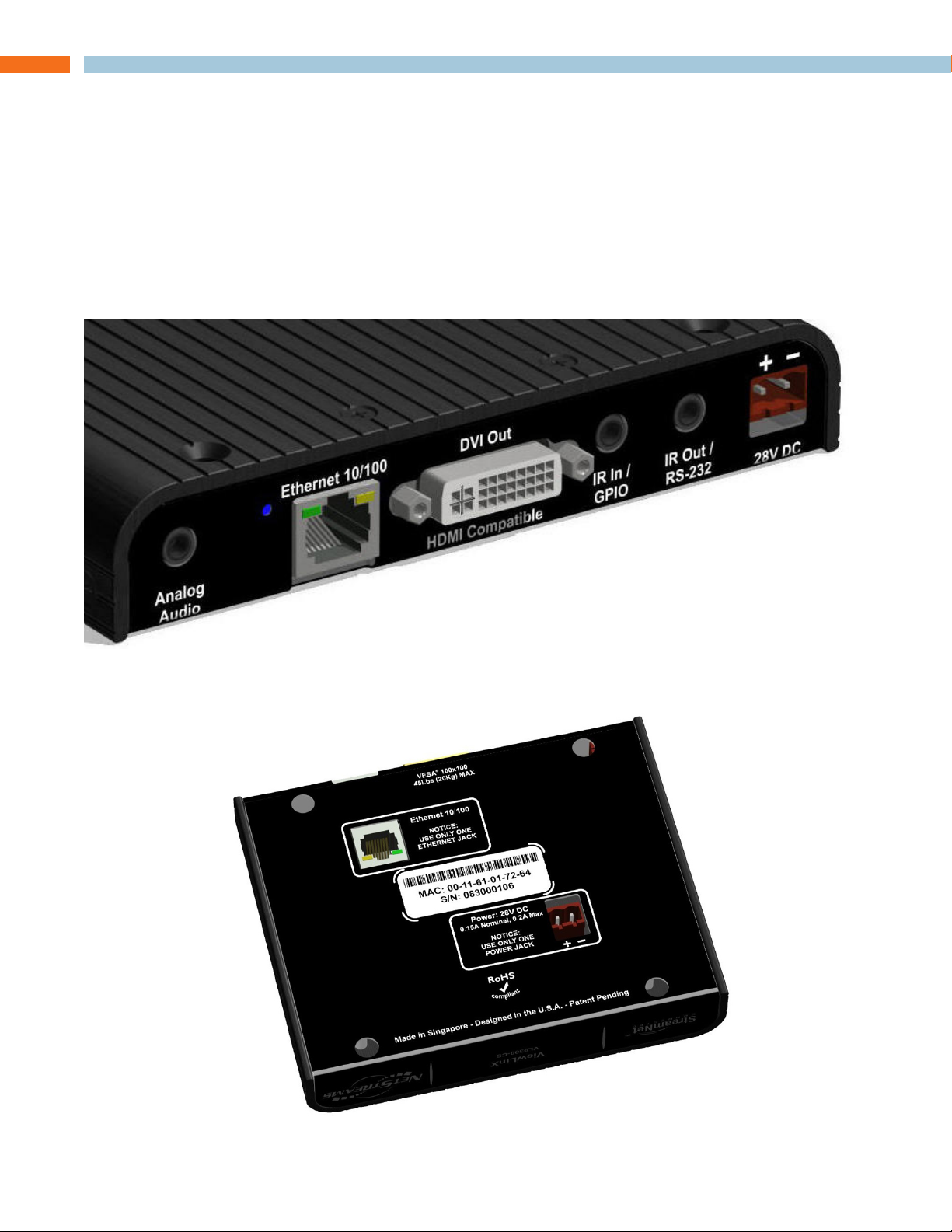
Electrical Connections
The ViewLinX VL9300 has connectors on the back and underneath the unit for flexibility in use.
1x - DVI, HDMI-compatible output connector.•
2x - 10/100 Ethernet jacks; at back and on bottom. (Use one at a time) •
2x - Two-pin, 5mm, male, terminal block power connectors; at back and on bottom. (Use one •
at a time)
3x - 3.5mm three-conductor phone jacks.•
in s t a L L a t i o n Ma n u a L 2
Page 6

an a L o g au D i o
This 3.5mm three-conductor phone jack provides stereo audio output or stereo audio input depending on the configuration.
Di g i ta L au D i o
Digital audio output is also available on the HDMI-compatible DVI connector.
st a t u s LeD
This small blue LED lights up when the unit is powered up.
10/100 et h e r n e t Ja C k s
Each of the two 10/100 Ethernet connectors allow connection to a TCP/IP network that is setup to
run StreamNet. While there are two Ethernet connectors on the VL9300, only one may be used at a
time. Attempting to use both connectors at the same time will disrupt the network signal. The two
connectors are not connected to an internal network switch, and may not be used to daisy-chain
another Ethernet device. The purpose of these two discrete connectors is explained later in this
document. (See Physical Installation section.)
DVi ou t
The DVI connector on the VL9300 transmits digital video and audio. The signal is compatible with
HDMI when used with a standard DVI to HDMI adapter. While the DVI connector is physically compatible with a DVI-I cable, there are no analog video signals on the connector. DVI was selected
as the video connector to ensure a more robust connector type. A DVI connector has mounting
screws that can secure the output cable to the enclosure.
ir in / gpio
This 3.5mm three conductor jack allows connection of either a NetStreams infrared receiver, or NSVLCOM GPIO accessory device. The infrared receiver can pick up IR remote control signals and
pass them onto the StreamNet network. The NS-VLCOM GPIO accessory (sold separately) allows
up to four contact closure sensors, and four contact closure outputs to be added to the VL9300.
The NS-VLCOM also has IR pass-though. Can control CEC equiped displays with optional CEC
adapter.
The use of this is defined by the customer requirement. Consult the System Installation Manual for
further information.
ir ou t / rs -232
This 3.5mm three conductor phone jack allows the VL9300 to control a television, or other connected device. It supports sending infrared remote signals, or bidirectional RS-232 serial data signals. Only one type of signal may be configured at a time. Use is defined by customer requirement.
Consult System Installation Manual for further information.
10 - 28VDC in p u t
This 5.0mm two pin terminal block connector provides power input for the VL9300. There are two
power connectors on the VL9300. They are diode protected such that power does not pass from
one connector and out the other. They cannot be used to extend a run of power (daisy chain) to
another device. For larger system installation please consult the System Setup Manual.
Video Test Patterns - Consult StreamNet Software instructions for access to and use of video test
patterns in a system installation.
3 te C h n i C a L su p p o r t : 800.283.5936
Page 7

Installation
PHYSICAL CHARACTERISTICS
Di M e n s i o n s (eX C L u D i n g Co n n e C t o r s )
Width: 5.75 inches (146mm)
Length: 4.57 inches (116mm)
Height: 1.00 inch (25.4mm)
Three units will fit by side on a standard 19-inch rack shelf. The unit is only one inch thick allowing
installation behind even the thinnest televisions and monitors.
en C L o s u r e
The enclosure lid is made using a strong wrap-around aluminum extrusion finished with a black
anodized surface providing solid, durable protection for the VL9300.
sp e C i a L Du a L et h e r n e t a n D po w e r Co n n e C t i o n s
The VL9300 has two 10/100 Ethernet jacks, and two power input jacks making product installation
more versatile. Only one of each type may be connected at any one time.
The Ethernet and power connections are made from either inside a wall to the underside of the
unit, or from outside the wall to the back of the unit. The status lights on both Ethernet connectors
indicate data connection regardless of which jack is in use, allowing diagnosis of network connection.
METHODS FOR MOUNTING THE VL9300
wa L L Mo u n t
This bracket, included with the VL9300, includes long standoffs that pass into the enclosure. This
ensures the unit will not slip off the bracket during installation. The bracket can mount over a standard 2-gang wall box or zip-ring. This configuration is what allows the power and Ethernet cables to
be hidden inside the wall. The 100x100 mounting holes are symmetrical so the unit can be installed
with the external cables approaching from any direction.
in s t a L L a t i o n Ma n u a L 4
Page 8

su r f a C e Mo u n t
The same bracket used for a wall mounting over a wall box can be used to mount the VL9300 directly on a solid surface. When mounted on a flat surface all the I/O connections on the VL9300 are
accessible from the back of the unit as shown below.
Because the VL9300 is only 1-inch thick, and the cables exit out the back of the unit, it actually
takes less depth to plug a DVI cable into the VL9300 than to connect it directly to a connector in a
wall plate.
Vesa Mo u n t
The VL9300 mounting holes are positioned at 100x100 mm. This, along with the strong enclosure,
allows the VL9300 to mount directly to the back of a monitor, television or projector as long as the
monitor is compatible with the VESA 100x100 mounting standard. These are typically televisions or
monitors with a display size up to 36 inches, or a weight up to 45 lb. Different types of VESA mounts
may require extra hardware that is not included with the VL9300.
5 te C h n i C a L su p p o r t : 800.283.5936
Page 9

Software Setup of the VL9300
The VL9300 is setup for use in the commerical or residential network using the StreamNet Dealer
Setup program and the acompanying StreamNet Dealer Setup manual. StreamNet Dealer Setup is
a PC-based program that allows you to configure devices so that they can communicate across a
StreamNet network. Phases of the software setup include:
Opening the existing project•
Set sources for compression•
Any video sources within the Network that will be viewed using the VL9300 decoder »
(MLAV300 or MLAV9300-CS), must be in configured for compression using the
Sources Tab for those devices.
Find the new device•
Matching the new VL9300 physical hardware device to the hardware setup in the project•
Configuring the device with system-specific information•
Saving the project•
Sending the configuration files to the server•
These steps involved in these processes are detailed in the DigiLinX Dealer Setup manual available
for viewing or download at www.netstreams.com.
Verify the configuration information on the tabs for the Gateway VL device as shown in the following
screens:
in s t a L L a t i o n Ma n u a L 6
Page 10

7 te C h n i C a L su p p o r t : 800.283.5936
Page 11

in s t a L L a t i o n Ma n u a L 8
Page 12

9 te C h n i C a L su p p o r t : 800.283.5936
Page 13

Compliance
Co M p L i a n C e oV e r V i e w
ROHS COMPLIANCE
All components and processes used to produce the VL9300 will comply with the RoHS initiative.
SUSTAINABILITY
The VL9300 is compliant with the WEEE recycling initiative. It is made from easily recyclable materials such as aluminum and steel.
ELECTRICAL SAFETY ADVISORY
This equipment uses DC power supplied from an external source which can be subjected to electrical surges, typically lightning transients which are very destructive to customer terminal equipment.
The warranty for this equipment does not cover damage caused by electrical surge or lightning
transients. To reduce the risk of this equipment becoming damaged it is suggested that the customer consider installing a surge arrestor.
Any modifications to the device without express authorization from ClearOne is prohibited as per
47CFR15.21 and could void the users authority to operate the device.
Co M p L i a n C e De t a i L s
FCC COMPLIANCE
FCC Part 15: This device complies with FCC Part 15 regulations for a Class A device.
NOTE: This equipment has been tested and found to comply with the limits for a Class »
A digital device, pursuant to part 15 of the FCC Rules. These limits are designed to
provide reasonable protection against harmful interference when the equipment is
operated in a commercial environment. This equipment generates, uses, and can
radiate radio frequency energy and, if not installed and used in accordance with the
instruction manual, may cause harmful interference to radio communications. Operation of this equipment in a residential area is likely to cause harmful interference in
which case the user will be required to correct the interference at his own expense.
EUROPEAN COMPLIANCE
Details on European equipment compliance can be found on the ClearOne website at the following
location: www.ClearOne.com/resources/EuroDOC.php
in s t a L L a t i o n Ma n u a L 10
Page 14

Service and Support
If you need assistance setting up or operating your product, please contact us. We welcome your
comments so we can continue to improve our products and better meet your needs.
te C h n i C a L su p p o r t
Telephone: 1.800.283.5936
E-mail: tech.support@ClearOne.com
Web site: www.ClearOne.com, www.NetStreams.com
sa L e s
Telephone: 1.800.707.6994
E-mail: sales@ClearOne.com
te C h s a L e s
Telephone: 1.800.705.2103
E-mail: techsales@ClearOne.com
pr o D u C t re t u r n s
All product returns require a Return Material Authorization (RMA) number. Contact ClearOne Technical Support before returning your product. Make sure you return all the items and packing materials that originally shipped with your product.
CLEARONE LOCATIONS
HEADQUARTERS:
Salt Lake City, UT USA
5225 Wiley Post Way
Suite 500
Salt Lake City, UT 84116
Tel: 801.975.7200
Toll Free: 800.945.7730
Fax: 801.977.0087
e-mail: sales@clearone.com
EMEA
Tel: 44 (0) 1189.036.053
e-mail: global@clearone.com
APAC
Tel: 801.303.3388
e-mail: global@clearone.com
11 te C h n i C a L su p p o r t : 800.283.5936
AVOIP™
LATAM
Tel: 801.974.3621
e-mail: global@clearone.com
Technical Sales
Tel: 800.705.2103
e-mail: techsales@clearone.com
Technical Support
Tel: 800.283.5936
e-mail: tech.support@clearone.com
 Loading...