

Page 1

VIEW® Pro D310
High-definition, IP, Compressed Audio/Video Decoder
Quick-Start Guide
Page 2

THE VIEW PRO ENCODER AND DECODER ................................ 1
QUICK-START OVERVIEW ............................................................ 1
ENCODER AND DECODERS IN A NETWORK ............................. 2
PARTS INCLUDED ......................................................................... 3
MOUNTING THE D310 DECODER ................................................ 4
CONNECTING THE DECODER ..................................................... 6
CONFIGURING THE DECODER.................................................... 7
PART NUMBERS .......................................................................... 15
Table of Contents
Page 3

VIEW PRO D310 QUICK-START GUIDE
1
THE VIEW PRO ENCODER AND DECODER
ClearOne’s VIEW Pro D310 decoder delivers the ultimate in high-quality,
low-latency, 4:2:0 YCbCr color space digital media at unrivaled cost
advantage. Distribution of all digital media is via existing IP networks and
infrastructure to single-image, full-screen video applications.
ClearOne StreamNet® technology embedded within VIEW Pro encoders
and decoders also facilitates automatic discovery, control, monitoring
and distribution within StreamNet networks.
The VIEW Pro D310 decoder takes the combined video and audio
stream, usually provided from a VIEW Pro encoder, decodes it, and then
sends the video and audio to a display such as a HDTV or projector and
sound system.
The latest version of the VIEW CONSOLE software can be found on the
ClearOne website at http://www.clearone.com/resources#network_
media_streaming.
QUICK-START OVERVIEW
You will be performing these steps in the following order to use the VIEW
Pro D310 Decoder in your StreamNet network:
1. Mounting the D310 Decoder (Optional)
2. Connecting the D310 Decoder
3. Configuring the D310 Decoder
Page 4

VIEW PRO ENCODER & DECODER
2
ENCODER AND DECODERS IN A NETWORK
The VIEW Pro encoder receives input from an AV source device such as
BluRay Player, DVD Player, etc. and distributes it over a StreamNet TCP/
IP network using a standard 100 Mbit or Gbit Ethernet connection. The
encoder provides the IP data for VIEW Pro decoders to deliver to the
displays, therefore decoders are installed at the locations of the target
video displays.
This picture shows an example for connecting VIEW Pro devices in a
network.
Page 5
VIEW PRO D310 QUICK-START GUIDE
3
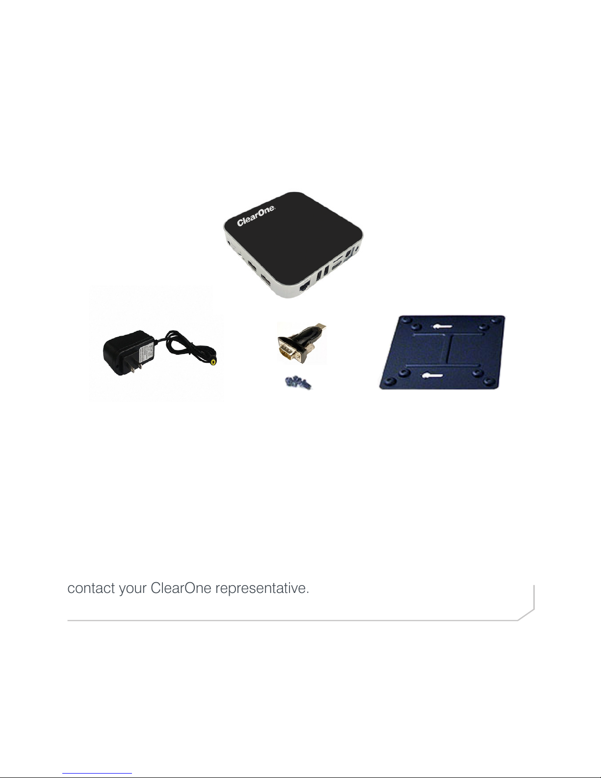
PARTS INCLUDED
The following items are included with the VIEW Pro D310 Decoder:
• D310 Decoder Unit
• Power Supply
• Mounting Plate
(VESA, holes spaced 100 mm X 100 mm, 3.9 inches X 3.9 inches)
• Mounting Screws for Mounting Plate and D310 Unit
• USB to DB9 Serial Adapter
Verify that all items have been received. If there is any issue, please
contact your ClearOne representative.
Page 6

VIEW PRO ENCODER & DECODER
4
MOUNTING THE D310 DECODER
The D310 includes a Mounting Plate and screws. The Mounting Plate can
be used on a wall or for applications where a decoder must be located
on a VESA mount, such as on the back of a monitor.
Attach the Mounting Plate to a display with the 4 phillips-head screws.
(Figure 1)
Insert the 2 screws with the extended heads into the back of the D310
and tighten. (Figure 2)
NOTE: Although the Mounting Plate does attach the decoder to
the back of a display, it also allows the decoder to be attached to a
separate VESA mount.
Figure 1
Page 7

VIEW PRO D310 QUICK-START GUIDE
5
Align the D310 with the Mounting Plate so that indicator arrows on the
plate and the decoder are pointed upward. Insert the heads of the
extended screws on the D310 into the keyhole slots of the Mounting
Plate and slide down to secure.
Figure 2
Figure 3
Page 8

VIEW PRO ENCODER & DECODER
6
CONNECTING THE DECODER
Connect the D310 Decoder to:
• Ethernet LAN where the encoders and the computer running the VIEW
CONSOLE program are connected
• HDMI Audio/Video output to the HDMI input on the display or projector
• USB 3.0 ports can be used by the USB to DB9 Serial Adapter allowing
serial communication to/from the unit
• A provided DC power supply
NOTE: Carefully run the connected cables so they do not put strain on
the connectors.
HDMI
Audio/Video Out
Ethernet
Connection
to Network
DC In
USB 3.0 Ports
(future use)
S/PDIF (Optical)
USB 3.0 Port
(future use)
Internal Use
Only
AV Output
(SD Resolution)
Power
On/O
Internal Use
Only
Page 9

7
CONFIGURING THE DECODER
The VIEW Pro D310 Decoder is configured for use in the network with the
VIEW CONSOLE program. VIEW CONSOLE is a PC-based program that
allows you to configure devices so that they can communicate across a
StreamNet network. Phases of the software setup include:
• Create a new or open an existing project
• Add the D310 device to the project
• Match the correct device from the right-hand column.
• Configuring the device with system-specific information regarding
Display Outputs, Controls, IP.
• Saving the project
• Sending the configurations
These steps in these processes are detailed in the VIEW CONSOLE user
manual available for viewing or download at www.ClearOne.com.
NOTE: VIEW CONSOLE version 3.02.xx or later is required to
support the D310 decoder.
Information specific to the VIEW Pro Decoder is contained in the VIEW
Pro - D310 Digital AV Decoder Installation and Users Manual available
for viewing or download at www.clearone.com. (The steps for using the
VIEW CONSOLE program and options for the D310 are similar to those
of the D210 decoder).
VIEW PRO D310 QUICK-START GUIDE
Page 10

VIEW PRO ENCODER & DECODER
8
Create a New or Open an Existing Project
Add the VIEW Pro D310 to the Project
Page 11

9
Match the Correct Device from the Right-Hand Column
VIEW PRO D310 QUICK-START GUIDE
Page 12

VIEW PRO ENCODER & DECODER
10
Configuring: Info Tab for D310
Page 13

11
Configuring: Info Tab Advanced Options for D310
VIEW PRO D310 QUICK-START GUIDE
Page 14

VIEW PRO ENCODER & DECODER
12
Configuring: Display Outputs Tab for D310
Page 15

13
Configuring: Display Controls Tab for D310
VIEW PRO D310 QUICK-START GUIDE
Page 16

VIEW PRO ENCODER & DECODER
14
Sending the Configurations
With the project still open to the changes you just made, select the
Send Configuration to Device icon or, in the case of multiple devices,
the Send Configuration to Multiple Devices icon. This will send the
configuration setting to the device(s).
Wait for the device(s) to restart.
These steps in these processes are detailed in the VIEW CONSOLE
manual available for viewing or download at www.ClearOne.com.
Saving the Project
Select File>Save to save the project.
Page 17

CONTACT INFORMATION
HEADQUARTERS:
Salt Lake City, UT USA
5225 Wiley Post Way
Suite 500
Salt Lake City, UT 84116
Sales: 800.705.2103
Toll Free: 800.945.7730
Fax: 801.303.5711
e-mail: sales@clearone.com
TechSales
Tel: 800.705.2103
e-mail: techsales@clearone.com
Technical Support
Tel: 800.283.5936
e-mail: tech.support@clearone.com
Europe:
Tel: +44.1454.616.977
UK Tech Support: +44.0800.680.0682
General Tech Support: +1.800.283.5936
e-mail: global@clearone.com
Asia Pacific:
Tel: +86.138.23287825
Tech Support: +86.18420152949
e-mail: global@clearone.com
Middle East:
Tel: +91.9930782195
e-mail: global@clearone.com
Other Regions:
Tel: +1.801.975.7200
e-mail: global@clearone.com
© 2016 ClearOne, Inc. All rights reserved.
Information in this document is subject to change without notice. QSG-0030-001 Revision 1.1 AUGUST 2016
15
PART NUMBERS
910-0003-002 VIEW Pro Decoder D310
910-0003-001 VIEW Pro Decoder D210
910-0001-001 VIEW Pro Decoder D110
910-0000-001 VIEW Pro Encoder E120
910-0000-006 VIEW Pro Encoder E110
VIEW PRO D310 QUICK-START GUIDE
 Loading...