

Page 1

A–Series
Setup and Installation Guide
Revision 1.6.05.10.2013
Page 2

Technical Support
See the Support Web site for documentation, technical updates, drivers and downloads,
warranty information, and software revisions.
Web:
Email: support@clearcube.com
Phone: (512) 652-3400 or call toll free (866) 652-3400 (United States)
http://www.clearcube.com/support/
Corporate Headquarters
ClearCube Technology, Inc.
3700 W Parmer Ln
Austin, Texas 78727
Email:
Phone: (512) 652-3500 or call toll free (866) 652-3500 (United States)
Fax: (512) 652-3501
Or your local ClearCube Reseller or Authorized Service Provider
Copyrights
© 2013 by ClearCube Technology, Inc. All rights reserved. Under copyright laws, this
publication may not be reproduced or transmitted in any form, electronic or mechanical,
including photocopying, recording, storing in an information retrieval system, or translating, in
whole or in part, without the prior written consent of ClearCube Technology, Inc.
This information is subject to change without notice and ClearCube shall not be liable for any
direct, indirect, special, incidental or consequential damages in connection with the use of this
material.
info@clearcube.com
Trademarks
ClearCube™, Sentral™, Blade Switching BackPack™, PC Blade™, C/Port™, and I/Port™
are trademarks of ClearCube Technology, Inc. Product and company names mentioned herein
are trademarks or trade names of their respective companies.
Patents
The ClearCube Architecture and its components described in this user manual are protected by
numerous granted and pending U.S. and international patents.
Granted patents include: US05926172, US05966056, US05994952, US06012101 ,
US06020839, US06037884, US06038616, US06119146, US06148182, US06167241,
US06385666, US06421393, US06426970, US06633934, US06708247, US06735658, and
US06886055.
Patents pending include: US S/N 09/755378, US S/N 10/279475, US S/N 10/198719, US S/N
10/198650, US S/N 10/409219, US S/N 09/728667, US S/N 09/728669, US S/N 10/411804,
US S/N 10/411908, US S/N 10/458853, US S/N 10/364584, US S/N 10/301536, US S/N
60/411066, US S/N 10/662933, US S/N 10/662889, US S/N 10/662932, US S/N 10/662968,
US S/N 10/301563, US S/N 10/662936, US S/N 10/301518, US S/N 10/662955 and US S/N
10/662954.
Inquiries regarding patented technology should be directed to ClearCube Corporate
Headquarters.
Page 3

Contents
How to Use This Guide . . . . . . . . . . . . . . . . . . . . . . . . . . . . . . . . . . . . . . . . . . . . . . . . . . . . . . . . . . . vii
FCC Warning . . . . . . . . . . . . . . . . . . . . . . . . . . . . . . . . . . . . . . . . . . . . . . . . . . . . . . . . . . . . . . . . . . . vii
California Proposition 65 Statement . . . . . . . . . . . . . . . . . . . . . . . . . . . . . . . . . . . . . . . . . . . . . . . . . vii
WEEE Information . . . . . . . . . . . . . . . . . . . . . . . . . . . . . . . . . . . . . . . . . . . . . . . . . . . . . . . . . . . . . . vii
Medical and Clinical Use of ClearCube Products . . . . . . . . . . . . . . . . . . . . . . . . . . . . . . . . . . . . . . viii
Symbols . . . . . . . . . . . . . . . . . . . . . . . . . . . . . . . . . . . . . . . . . . . . . . . . . . . . . . . . . . . . . . . . . . . . . . . ix
Safety Guidelines . . . . . . . . . . . . . . . . . . . . . . . . . . . . . . . . . . . . . . . . . . . . . . . . . . . . . . . . . . . . . . . . . x
Chapter 1. A–Series Architecture and Product Overview . . . . . . . . . . . . . . . . . . . . . . . . . . . . . 1
1.1 A–Series Blade PCs . . . . . . . . . . . . . . . . . . . . . . . . . . . . . . . . . . . . . . . . . . . . . . . . . . . . . . . . . . 2
1.1.1 Blade PC Overview, Identification Labels, and Serial Number . . . . . . . . . . . . . . . . . . . . 3
1.1.1.1 Blade PC Components . . . . . . . . . . . . . . . . . . . . . . . . . . . . . . . . . . . . . . . . . . . . . . . 4
1.1.1.2 Blade PC Identification Labels . . . . . . . . . . . . . . . . . . . . . . . . . . . . . . . . . . . . . . . . . 5
1.1.1.3 Blade PC Serial Number . . . . . . . . . . . . . . . . . . . . . . . . . . . . . . . . . . . . . . . . . . . . . . 5
1.1.2 A6106D Blade PC . . . . . . . . . . . . . . . . . . . . . . . . . . . . . . . . . . . . . . . . . . . . . . . . . . . . . . . 5
1.1.3 A6105D Blade PC . . . . . . . . . . . . . . . . . . . . . . . . . . . . . . . . . . . . . . . . . . . . . . . . . . . . . . . 6
1.2 A–Series Chassis and Expansion Backplane . . . . . . . . . . . . . . . . . . . . . . . . . . . . . . . . . . . . . . . 7
1.3 Cloud Desktops: Zero Clients and Thin Clients . . . . . . . . . . . . . . . . . . . . . . . . . . . . . . . . . . . . . 9
1.4 Monitor Support and Requirements . . . . . . . . . . . . . . . . . . . . . . . . . . . . . . . . . . . . . . . . . . . . . 10
Chapter 2. Site Preparation and Network Planning . . . . . . . . . . . . . . . . . . . . . . . . . . . . . . . . . 11
2.1 About Your Shipment . . . . . . . . . . . . . . . . . . . . . . . . . . . . . . . . . . . . . . . . . . . . . . . . . . . . . . . . 11
2.1.1 Inspecting Your Shipment and Devices . . . . . . . . . . . . . . . . . . . . . . . . . . . . . . . . . . . . . . 11
2.1.2 Unpacking Your Shipment . . . . . . . . . . . . . . . . . . . . . . . . . . . . . . . . . . . . . . . . . . . . . . . 12
2.2 Rack and Cabinet Requirements . . . . . . . . . . . . . . . . . . . . . . . . . . . . . . . . . . . . . . . . . . . . . . . . 13
2.2.1 Space and Floor Support . . . . . . . . . . . . . . . . . . . . . . . . . . . . . . . . . . . . . . . . . . . . . . . . . 14
2.2.2 Cooling and Airflow . . . . . . . . . . . . . . . . . . . . . . . . . . . . . . . . . . . . . . . . . . . . . . . . . . . . 14
2.3 Chassis and Blade Power Requirements . . . . . . . . . . . . . . . . . . . . . . . . . . . . . . . . . . . . . . . . . . 15
2.3.1 Power Input Considerations . . . . . . . . . . . . . . . . . . . . . . . . . . . . . . . . . . . . . . . . . . . . . . . 15
2.3.2 Power Circuit Considerations . . . . . . . . . . . . . . . . . . . . . . . . . . . . . . . . . . . . . . . . . . . . . 16
iii
Page 4

2.4 Chassis Expansion Backplane and Cabling . . . . . . . . . . . . . . . . . . . . . . . . . . . . . . . . . . . . . . . 16
2.4.1 Chassis Ports and Supported Protocols . . . . . . . . . . . . . . . . . . . . . . . . . . . . . . . . . . . . . . 16
2.4.2 Ethernet Cable Requirements . . . . . . . . . . . . . . . . . . . . . . . . . . . . . . . . . . . . . . . . . . . . . 17
2.4.3 Supported Cables . . . . . . . . . . . . . . . . . . . . . . . . . . . . . . . . . . . . . . . . . . . . . . . . . . . . . . . 18
2.5 Example Deployment Diagrams . . . . . . . . . . . . . . . . . . . . . . . . . . . . . . . . . . . . . . . . . . . . . . . . 18
2.5.1 Dedicated PCoIP Network . . . . . . . . . . . . . . . . . . . . . . . . . . . . . . . . . . . . . . . . . . . . . . . . 19
2.5.2 Shared Network . . . . . . . . . . . . . . . . . . . . . . . . . . . . . . . . . . . . . . . . . . . . . . . . . . . . . . . . 20
Chapter 3. Chassis and Blade PC Installation . . . . . . . . . . . . . . . . . . . . . . . . . . . . . . . . . . . . . 21
3.1 Tools for Installation . . . . . . . . . . . . . . . . . . . . . . . . . . . . . . . . . . . . . . . . . . . . . . . . . . . . . . . . . 21
3.2 Installing an A–Series Chassis . . . . . . . . . . . . . . . . . . . . . . . . . . . . . . . . . . . . . . . . . . . . . . . . . 21
3.2.1 Chassis Container Contents . . . . . . . . . . . . . . . . . . . . . . . . . . . . . . . . . . . . . . . . . . . . . . . 22
3.2.2 Chassis AC Power Cords . . . . . . . . . . . . . . . . . . . . . . . . . . . . . . . . . . . . . . . . . . . . . . . . . 23
3.2.3 Mounting A–Series Chassis . . . . . . . . . . . . . . . . . . . . . . . . . . . . . . . . . . . . . . . . . . . . . . . 23
3.2.3.1 Cabinet Mounting Considerations . . . . . . . . . . . . . . . . . . . . . . . . . . . . . . . . . . . . . 23
3.2.3.2 Using a Chassis Accessory Kit . . . . . . . . . . . . . . . . . . . . . . . . . . . . . . . . . . . . . . . . 24
3.2.3.3 Using a Chassis Rapid–Mount Kit . . . . . . . . . . . . . . . . . . . . . . . . . . . . . . . . . . . . . 25
3.2.3.4 Removing a Rapid–Mount Kit Bracket . . . . . . . . . . . . . . . . . . . . . . . . . . . . . . . . . 27
3.2.4 Attaching and Removing the Expansion Backplane . . . . . . . . . . . . . . . . . . . . . . . . . . . . 28
3.2.4.1 Attaching the Expansion Backplane . . . . . . . . . . . . . . . . . . . . . . . . . . . . . . . . . . . . 28
3.2.4.2 Removing the Expansion Backplane . . . . . . . . . . . . . . . . . . . . . . . . . . . . . . . . . . . 29
3.2.5 Chassis Power and Failover Power Feature . . . . . . . . . . . . . . . . . . . . . . . . . . . . . . . . . . . 30
3.2.5.1 To Enable Chassis Failover Power Feature . . . . . . . . . . . . . . . . . . . . . . . . . . . . . . 30
3.2.5.2 To Power Chassis without Failover Power Feature . . . . . . . . . . . . . . . . . . . . . . . . 31
3.3 Configuring A–Series Blade PCs before Installation . . . . . . . . . . . . . . . . . . . . . . . . . . . . . . . . 31
3.3.1 Viewing Pre-OS Video (BIOS and Network Boot, PXE Boot) . . . . . . . . . . . . . . . . . . . 31
3.3.1.1 Before You Begin . . . . . . . . . . . . . . . . . . . . . . . . . . . . . . . . . . . . . . . . . . . . . . . . . . 32
3.3.1.2 Connecting Devices . . . . . . . . . . . . . . . . . . . . . . . . . . . . . . . . . . . . . . . . . . . . . . . . 32
3.3.1.3 Create Session and View Video . . . . . . . . . . . . . . . . . . . . . . . . . . . . . . . . . . . . . . . 33
3.3.2 Operating System Images . . . . . . . . . . . . . . . . . . . . . . . . . . . . . . . . . . . . . . . . . . . . . . . . 34
3.3.2.1 Using the Default Operating System Image . . . . . . . . . . . . . . . . . . . . . . . . . . . . . . 35
3.3.2.2 Custom Operating System Requirements . . . . . . . . . . . . . . . . . . . . . . . . . . . . . . . . 35
3.3.2.3 Installing a Custom Image from an Image File Server . . . . . . . . . . . . . . . . . . . . . . 37
3.4 Installing Blade PC in a Chassis . . . . . . . . . . . . . . . . . . . . . . . . . . . . . . . . . . . . . . . . . . . . . . . . 38
iv
Page 5

3.5 Removing Blade PC from a Chassis . . . . . . . . . . . . . . . . . . . . . . . . . . . . . . . . . . . . . . . . . . . . . 39
Chapter 4. Upgrading and Maintaining Blade PCs . . . . . . . . . . . . . . . . . . . . . . . . . . . . . . . . . 41
4.1 Use Authorized Components . . . . . . . . . . . . . . . . . . . . . . . . . . . . . . . . . . . . . . . . . . . . . . . . . . 42
4.2 Replacing Components: Permitted and Prohibited Units . . . . . . . . . . . . . . . . . . . . . . . . . . . . . 42
4.3 Memory . . . . . . . . . . . . . . . . . . . . . . . . . . . . . . . . . . . . . . . . . . . . . . . . . . . . . . . . . . . . . . . . . . . 43
4.3.1 A6106D Memory Features . . . . . . . . . . . . . . . . . . . . . . . . . . . . . . . . . . . . . . . . . . . . . . . 43
4.3.2 A6105D Memory Features . . . . . . . . . . . . . . . . . . . . . . . . . . . . . . . . . . . . . . . . . . . . . . . 44
4.3.3 General Guidelines . . . . . . . . . . . . . . . . . . . . . . . . . . . . . . . . . . . . . . . . . . . . . . . . . . . . . 44
4.3.4 Population Guidelines . . . . . . . . . . . . . . . . . . . . . . . . . . . . . . . . . . . . . . . . . . . . . . . . . . . 45
4.3.5 Installing DIMMs . . . . . . . . . . . . . . . . . . . . . . . . . . . . . . . . . . . . . . . . . . . . . . . . . . . . . . 45
4.4 Hard Drives . . . . . . . . . . . . . . . . . . . . . . . . . . . . . . . . . . . . . . . . . . . . . . . . . . . . . . . . . . . . . . . . 46
4.4.1 A6106D . . . . . . . . . . . . . . . . . . . . . . . . . . . . . . . . . . . . . . . . . . . . . . . . . . . . . . . . . . . . . . 46
4.4.2 A6105D . . . . . . . . . . . . . . . . . . . . . . . . . . . . . . . . . . . . . . . . . . . . . . . . . . . . . . . . . . . . . . 47
4.5 BIOS . . . . . . . . . . . . . . . . . . . . . . . . . . . . . . . . . . . . . . . . . . . . . . . . . . . . . . . . . . . . . . . . . . . . . 49
4.5.1 Clearing BIOS Passwords . . . . . . . . . . . . . . . . . . . . . . . . . . . . . . . . . . . . . . . . . . . . . . . . 49
4.5.1.1 Before You Begin . . . . . . . . . . . . . . . . . . . . . . . . . . . . . . . . . . . . . . . . . . . . . . . . . . 50
4.5.1.2 Required Items . . . . . . . . . . . . . . . . . . . . . . . . . . . . . . . . . . . . . . . . . . . . . . . . . . . . 50
4.5.1.3 Setting up Zero Client and Blade PC . . . . . . . . . . . . . . . . . . . . . . . . . . . . . . . . . . . 50
4.5.1.4 Connecting Zero Client and Blade PC . . . . . . . . . . . . . . . . . . . . . . . . . . . . . . . . . . 52
4.5.1.5 Clearing Passwords . . . . . . . . . . . . . . . . . . . . . . . . . . . . . . . . . . . . . . . . . . . . . . . . . 53
4.5.2 Updating (Flashing) BIOS . . . . . . . . . . . . . . . . . . . . . . . . . . . . . . . . . . . . . . . . . . . . . . . . 53
4.5.3 Recovering BIOS . . . . . . . . . . . . . . . . . . . . . . . . . . . . . . . . . . . . . . . . . . . . . . . . . . . . . . . 54
Appendix A. Specifications . . . . . . . . . . . . . . . . . . . . . . . . . . . . . . . . . . . . . . . . . . . . . . . . . . . . 55
Appendix B. Regulatory Compliance . . . . . . . . . . . . . . . . . . . . . . . . . . . . . . . . . . . . . . . . . . . . 59
Appendix C. Support . . . . . . . . . . . . . . . . . . . . . . . . . . . . . . . . . . . . . . . . . . . . . . . . . . . . . . . . . . 61
C.1 Contact Information . . . . . . . . . . . . . . . . . . . . . . . . . . . . . . . . . . . . . . . . . . . . . . . . . . . . . . . . . 61
C.2 Return Merchandise Authorization (RMA) . . . . . . . . . . . . . . . . . . . . . . . . . . . . . . . . . . . . . . . 61
C.3 Power Cord Replacement . . . . . . . . . . . . . . . . . . . . . . . . . . . . . . . . . . . . . . . . . . . . . . . . . . . . . 62
Appendix D. Warranty . . . . . . . . . . . . . . . . . . . . . . . . . . . . . . . . . . . . . . . . . . . . . . . . . . . . . . . . . 63
Index . . . . . . . . . . . . . . . . . . . . . . . . . . . . . . . . . . . . . . . . . . . . . . . . . . . . . . . . . . . . . . . . . . . . . . . . 65
v
Page 6

vi
Page 7
How to Use This Guide
This guide explains how to install and set up ClearCube Technology, Inc. A–Series chassis,
blades and components necessary for managed desktop environments. We recommend that
you familiarize yourself with the ClearCube architecture and product descriptions and read
through all installation and setup procedures before beginning installation.
If you encounter any issues, contact ClearCube Support using the contact information
provided on the inside front cover of this manual and in Appendix C. “Support”
FCC Warning
This equipment generates and uses radio frequency energy and, if not installed and used in
strict accordance with the instructions in this manual, may cause interference to radio and
television reception. Changes or modifications not expressly approved by ClearCube
Technology, Inc. could void the user's authority to operate the equipment under FCC rules.
on page 61.
California Proposition 65 Statement
WARNING: ClearCube products contain chemicals, including lead, known to the
State of California to cause cancer, birth defects, or other reproductive harm.
Wash hands after handling.
ClearCube products should be disposed of in accordance with local laws governing computer
equipment disposal.
WEEE Information
The products described in this document are subject to regulation under the European Union
Directive 2002/96/EC, that mandates separate waste collection, treatment, and recycling of
electronic products. This directive is commonly known as WEEE, for Waste from Electrical
and Electronic Equipment, and its intent is to promote the safe and sensible disposal of
products that have outlived their usefulness.
ClearCube Technology, Inc. vii
Page 8

The “crossed-out” trash bin symbol, shown above, identifies products that should be recycled,
not simply discarded. ClearCube Technology, Inc. supports the reuse, recycling, recovery, and
responsible disposal of all products.
ClearCube Technology, Inc. is committed to meeting the requirements of the European Union
WEEE Directive. The goal of the directive is to reduce the environmental impact due to the
disposal of electrical and electronic equipment that has reached the end of its useful service life.
ClearCube products are sold exclusively to commercial and industrial customers and not to
private households. Under the WEEE legislation terms, commercial and industrial customers
have the responsibility to ensure that all electrical and electronic equipment is disposed of
properly and in accordance with all applicable laws and local regulations. For more
information, email r
Materials used in this product, if not disposed of properly, could have adverse effects on the
environment and on human health. Do not dispose of these products in unsorted municipal
waste containers. Deliver electronic waste only to an approved recycling facility, a treatment
facility, or both. If one is not available, contact ClearCube for assistance.
ecycle@clearcube.com, or call (866) 652-3400 or +1 (512) 652-3400.
Medical and Clinical Use of ClearCube Products
ClearCube products are not designed with components and testing for a level of reliability
suitable for use in or in connection with surgical implants or as critical components in any life
support systems whose failure to perform can reasonably be expected to cause significant
injury to a human. Applications of ClearCube products involving medical or clinical treatment
can create a potential for death or bodily injury caused by product failure, or by errors on the
part of the user. Because each end-user system environment is customized and differs from
ClearCube testing platforms and because a user may use ClearCube products in combination
with other products in a manner not evaluated or contemplated by ClearCube, the user is
ultimately responsible for verifying and validating the suitability of ClearCube products
whenever ClearCube products are incorporated in a system, including, without limitation, the
appropriate design, process and safety level of such system or application.
viii A–Series Setup and Installation Guide
Page 9
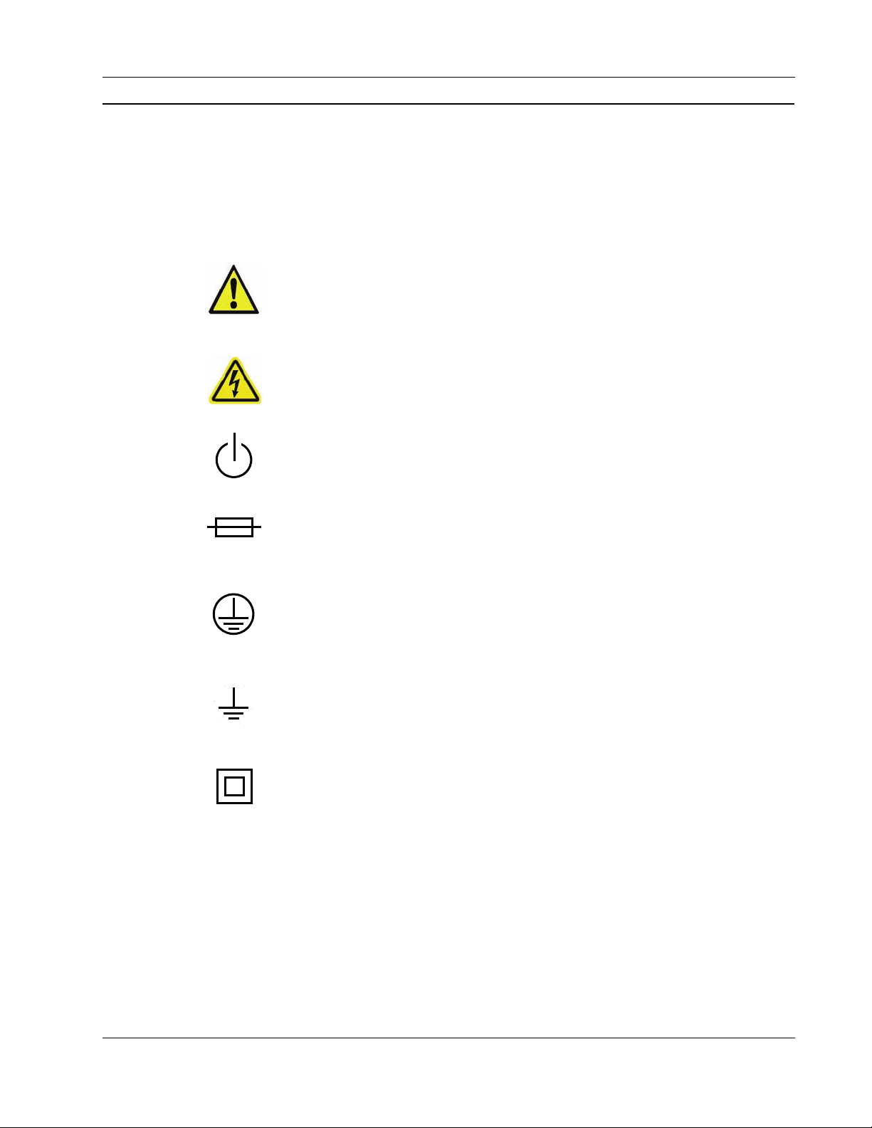
Symbols
Symbols are displayed on the hardware described in this document to convey specific
information to the operator and service person. It is important to understand the intended
meaning of these symbols. The following list shows each symbol displayed on ClearCube
Technology, Inc. products and explains the meaning of each symbol.
Refer to Manual
Used on the equipment’s rating label to direct the operator or service person to
this manual for additional information.
Shock Hazard
This symbol indicates the presence of electric shock hazards. Enclosures marked
with these symbols should only be opened by qualified service personnel. Refer
to the manual for additional information.
Power
Identifies the soft-start switch located on a blade used to power a blade on and
off.
Fuse
Located on equipment rating label. Symbol is accompanied with the
specifications needed for replacement. Only qualified technicians should
perform this operation.
Protective Earth Terminal
This symbol identifies the terminal that is used to connect all metal parts of an
enclosure through an external conductor to ground for protection against
electrical shock in a fault condition.
Ground Bond Terminal
This symbol identifies the ground bond terminal. This terminal is used to
connect the ground bonding conductor, or the combination of conductive parts,
to earth ground for safety purposes.
Equipment Protection Class II
May be located on the power adapter’s rating label. Indicates that equipment is
double–insulated from hazardous voltages. Not to be confused with Class 2, a
US National Electrical Code (NEC) circuit classification.
ClearCube Technology, Inc. ix
Page 10
The following caution and warning symbols are used in this document to indicate situations
that merit checking this or another manual, or situations that could result in damage to
equipment or physical injury.
CAUTION: A Caution notice in this manual indicates that equipment
damage or minor injury may result if proper procedures are not followed.
WARNING: A Warning notice in this manual indicates that catastrophic
equipment damage or serious injury, including death, may result if proper
procedures are not followed.
Safety Guidelines
Before undertaking any troubleshooting or maintenance procedure, carefully read all
WARNING and CAUTION notices. Equipment displaying warning or caution notices
contains voltage hazardous to human life and is capable of inflicting personal injury.
• Installations—You must install ClearCube equipment in accordance with local electrical
codes. Equipment might be subject to inspection.
• Chassis grounding—ClearCube’s chassis is designed with a three-conductor IEC 60320
appliance inlet that—with the proper power cord—connects the building’s external
protective earthing conductor to all accessible metal parts of the enclosure. To minimize
shock hazard, make sure your electrical power outlet has an appropriate earth safety
ground that is connected each time you power on the equipment.
Swedish safety regulations require the following statement:
—Apparaten skall anslutas till jordat uttag när den anslutas till ett nätuerk.—
Finnish safety regulations require the following statement:
— Laite on liitettävä suojamaadoituskoskettimilla varustettuun pistorasiaan.—
• Power cord selection—ClearCube or ClearCube distributors provide power cords that are
specifically designed for use with particular pieces of equipment and are approved for use
by the local authority having jurisdiction in the country where the equipment is put into
service. Refer to the installation sections of this manual for specific power cord
requirements. For information about obtaining replacement power cords, see
Appendix C. “Support”
on page 61.
• Power adapters—ClearCube or ClearCube distributors provide power adapters that are
specifically designed for use with particular pieces of equipment and are approved for use
x A–Series Setup and Installation Guide
Page 11

by the local authority having jurisdiction in the country where the equipment is put into
service. Refer to the installation sections of this guide for specific power cord
requirements. For information about obtaining replacement power adapters, see
Appendix C. “Support”
on page 61.
• IT power systems—ClearCube equipment has been evaluated and found to be compatible
with IT power distribution systems with a phase-to-phase voltage not to exceed 240 V.
• Live circuits—Operating personnel and service personnel must not remove protective
covers when operating the ClearCube chassis. Adjustments and service to internal
components must be undertaken by qualified service technicians. During any service of
this product, other than replacing a Blade PC or externally accessible modules on the
expansion backplane, the main connector to the premise wiring must be disconnected.
Dangerous voltages may be present under certain conditions. Use extreme caution.
• Explosive atmosphere—Do not operate the chassis in conditions where flammable gases
are present. Under such conditions this equipment is unsafe and may ignite the gases or
gas fumes.
•
Part replacement—
Only service equipment with parts that are exact electrical and
mechanical replacements. Contact your authorized ClearCube Technology, Inc. reseller for
information about replacement parts. Installation of parts that are not direct replacements will
void the warranty and may cause harm to personnel operating the chassis. Furthermore,
damage or fire may occur if replacement parts are unsuitable.
• Modification—Do not modify any part of the chassis or Blade PC from its original
condition. Modifications may result in hazards.
ClearCube Technology, Inc. xi
Page 12

xii A–Series Setup and Installation Guide
Page 13
Chapter 1. A–Series Architecture and
Product Overview
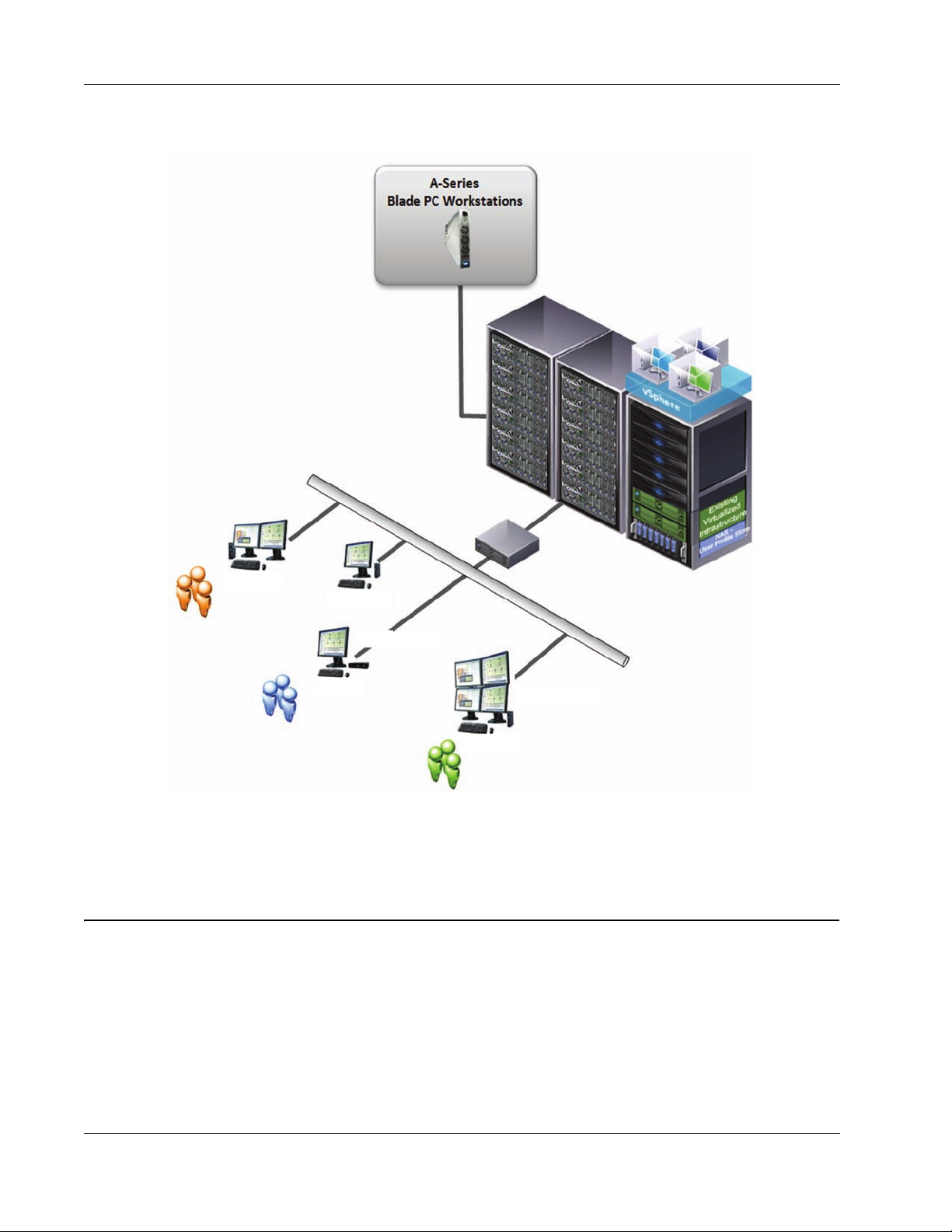
ClearCube A–Series architecture delivers PC functionality to users from a secure, centralized
location. This architecture increases IT manageability and security, and provides
mission-critical reliability, performance, and uptime improvements with lowered costs.
Replacing a traditional PC with a ClearCube Cloud Desktop (zero client or thin client) saves
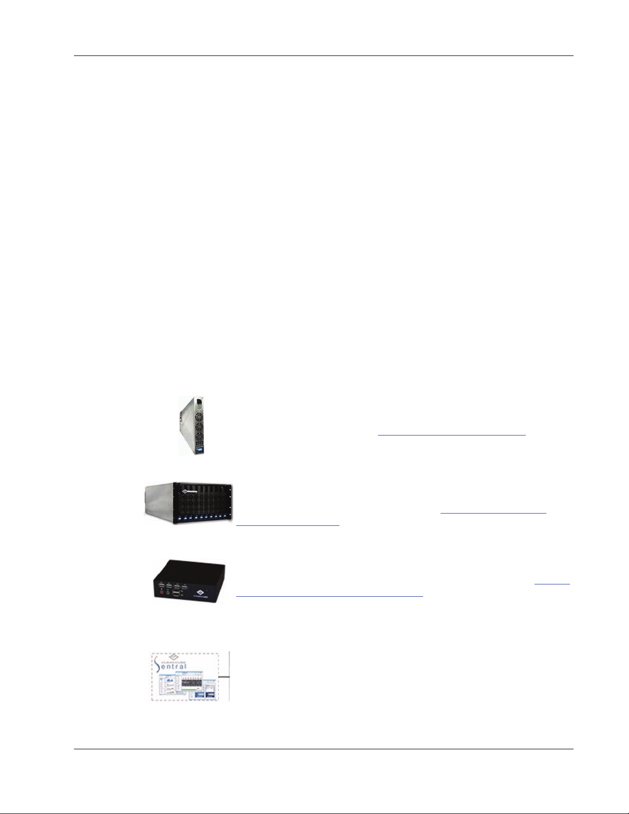
space, eliminates or reduces fan noise, and simplifies cabling. The key components of the
ClearCube architecture include (devices not shown to scale):
Blade PCs
Computers in a dense form factor that use Intel
typically remotely located. See “A–Series Blade PCs”
information about blades.
Chassis
Hold multiple Blade PCs and enable you to manage all external cables
connect to blades from a single location. See “A–Series Chassis and
Expansion Backplane” on page 7 for more information about chassis.
Cloud Desktop (zero client or thin client)
Physical devices, typically placed on a desk, to which you can connect
peripherals such as a monitor, keyboard, an d po inti ng d ev ice. See “Cloud
Desktops: Zero Clients and Thin Clients” on page 9 for more information
about zero clients and thin clients.
System management software and hardware
ClearCube Sentral™ is a software suite that provides system mana gement
capabilities (including connection brokering, mass storage lockout,
alerting, and much more) for your ClearCube environment. Sentral takes
advantage of monitoring hardware that is built into blades, chassis, and
Cloud Desktops. For more information about Sentral, see ClearCube
Sentral Administrator’s Guide.
®
CPUs. Blades are
on page 2 for more
A–Series Setup and Installation Guide 1
Page 14
Chapter 1. A–Series Architecture and Product Overview
Centralized Virtual
Desktops
Power Users
Knowledge Users
Task Users
VMware View
Client
Thin Client
Zero Client
Chassis
Zero Client
Network
Infrastructure
The picture below shows the A–Series architecture components.
Figure 1. A–Series architecture
1.1 A–Series Blade PCs
ClearCube A–Series Blade PCs are computers with Intel processors that deliver full PC
functionality to users, including USB functionality, from a centralized location. Each A–Series
Blade PC contains all the industry-standard components of a desktop PC:
• Processor
•Memory
2 A–Series Setup and Installation Guide
Page 15

• Hard disk
A–Series Blade PCs
• Video support (PCoIP
®
host card, GPU or graphics card, or integrated graphics)
• PCoIP host card (depending on configuration)
®
•Ethernet
network interface card (NIC)
You can connect USB peripherals to a Blade PC through USB ports on a Cloud Desktop (zero
client or thin client). You can install software on your Blade PC through a cloud desktop
network connection or by using peripherals connected to the USB ports.
1.1.1 Blade PC Overview, Identification Labels, and Serial Number
This figures in this section show
• An overview of an A–Series blade detailing the LCD bezel, buttons, and indicators, and
• all identification labels on a blade.
ClearCube Technology, Inc. 3
Page 16
Chapter 1. A–Series Architecture and Product Overview
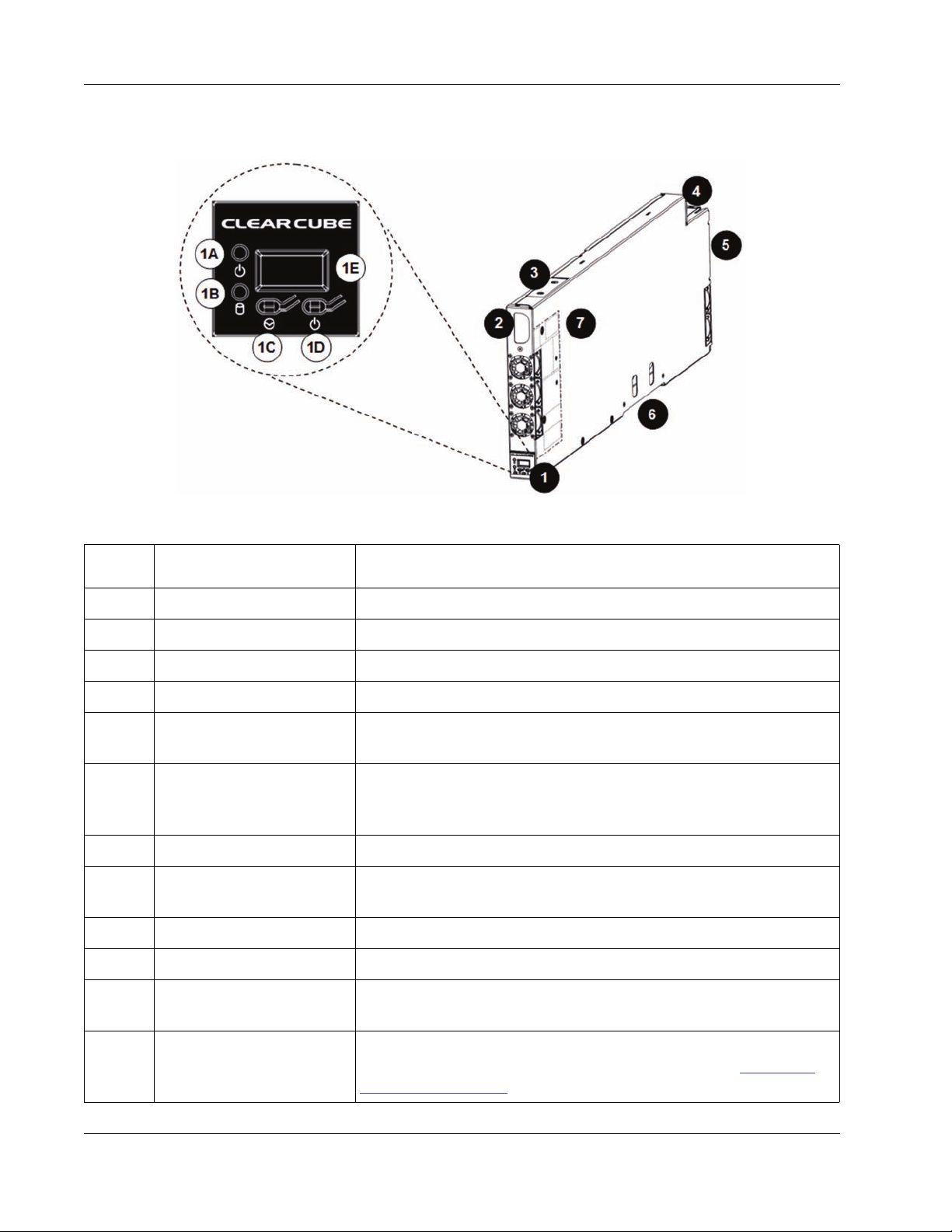
1.1.1.1 Blade PC Components
The picture and table below show each A–Series blade component.
Figure 2. A–Series blade components and features
Figure
Number
1 LCD bezel Provides indicators and power-related buttons.
1A Power indicator Illuminated when blade is powered on.
1B Drive activity indicator Flashes to indicate storage drive activity.
1C Reset button Press to reset blade power.
1D Power button
1E Display
2 Handle Use to aid insertion and removal from chassis.
3 I/O access slot
4 Power connector Connects to the AC power backplane on A3100 chassis.
5 Ethernet ports Connect to Ethernet ports on the A–Series chassis backplane.
Part Function
Press to power on or power off blade. Press and hold for 3 seconds
to force power off.
Displays boot codes and blade serial number. ClearCube Sentral
management suite enables the LCD to display user-defined strings
and to blink for identification purposes.
Provides access to select motherboard I/O ports for configuration
outside of a chassis.
Storage drive carrier
6
(A6106D model only)
7 Video configuration label
4 A–Series Setup and Installation Guide
Holds up to two storage drives (hard drives), connecting directly to SATA
connectors inside the blade. Does not support hot-swap operation.
Provides important blade configuration information, including video
host card MAC address, serial number, and more. See "Blade PC
Identification Labels" on page 5 for more information.
Page 17
A–Series Blade PCs
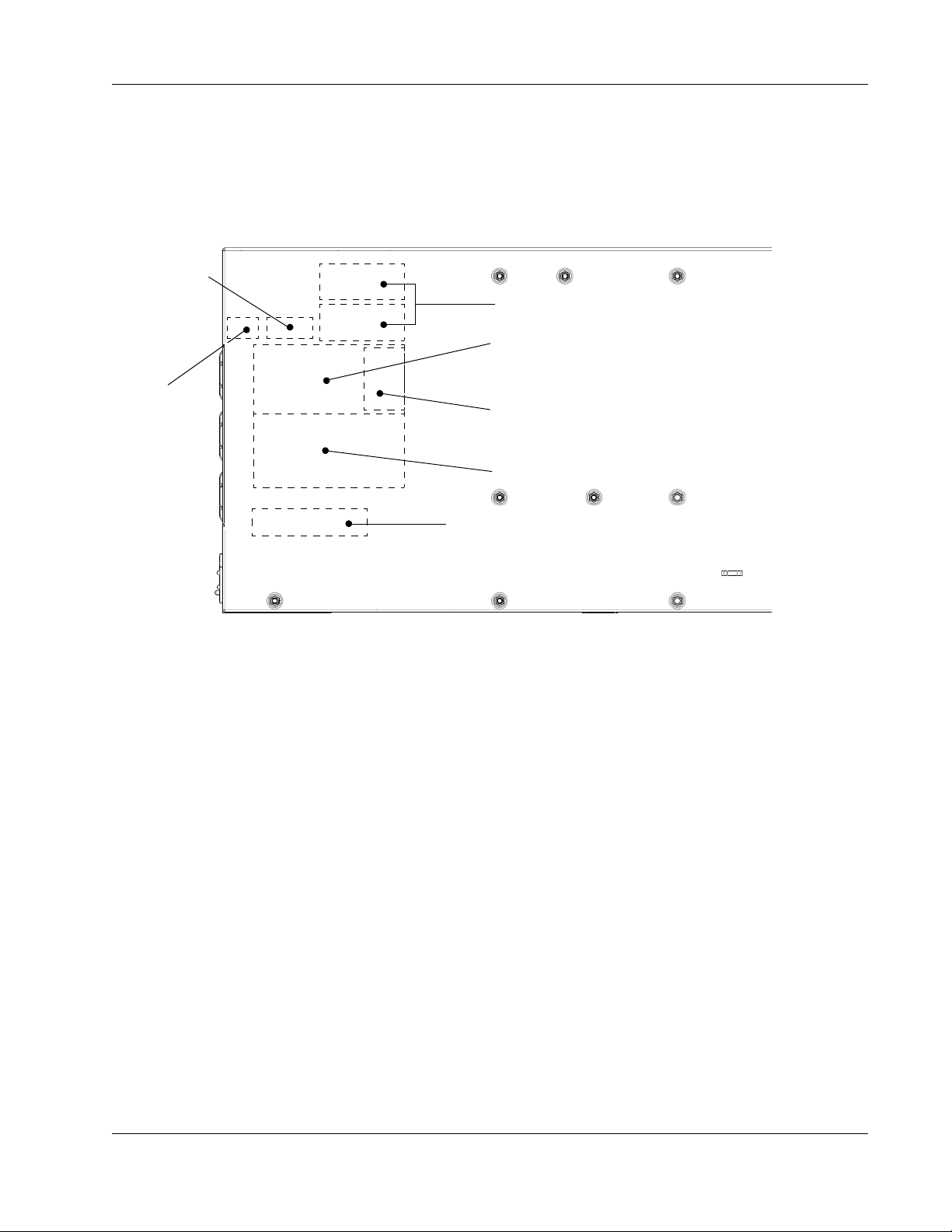
Intel Inside
Label
Blade Serial Number and MAC Label
Video Configuration Label(s)
System Configuration Label
Regulatory Label
Operating System COA Label
Host Card
Firmware
Revision Label
1.1.1.2 Blade PC Identification Labels
Labels on A–Series blades provide a variety of important information about the blade. Each
A–Series blade has a serial number. By default, the last three digits of the serial number are
displayed on the blade LCD. The serial number is also printed on a label adjacent to the fans
on the front of the blade, as shown in the following figure.
Figure 3. A–Series serial number and configuration labels
1.1.1.3 Blade PC Serial Number
The blade serial number (located on a label shown in the section above) is useful if yo u need to
identify a blade or a blade model. A–Series blade serial numbers use the following syntax:
• A6106D
AVCnnnnn (where AVC is the serial number prefix, and nnnnn is a five-digit number.)
• A6105D
AMBnnnnn (where AMB is the serial number prefix, and nnnnn is a five-digit number.)
The following sections detail the features of each A–Series blade.
1.1.2 A6106D Blade PC
Features of the A6106D include:
• Intel Q77 Express Chipset.
• Two Intel PRO 10/100/1000 Ethernet ports.
• One DVI-I port (for bench top configuration and setup only).
ClearCube Technology, Inc. 5
Page 18

Chapter 1. A–Series Architecture and Product Overview
•USB ports
– Inside chassis:
Two USB 2.0 ports
– On benchtop:
Two USB 3.0 ports (for bench top configuration and setup only)
• Four 240-pin DDR3 SDRAM DIMM sockets supporting:
– Up to 32 GB maximum total system memory using 4 Gb memory technology.
– Non-ECC DIMMs.
– DDR3 1600 MHz, 1333 MHz and 1066 MHz DIMMs.
• Supports dual- and quad-monitor zero clients compatible with PC–over–IP
®
(PCoIP)
technology.
• Front-mounted LCD:
– Displays last three number of serial number by default.
– Able to display user-specified text through ClearCube Sentral and to blink to aid in
identification.
1.1.3 A6105D Blade PC
Features of the A6105D blade include:
• Intel Q57 Express Chipset.
• Two 10/100/1000 Ethernet ports.
• One DVI-I port and one DVI-D port (for bench top configuration and setup).
• Two USB ports (for bench top configuration and setup).
• Chassis and standalone operation.
• Four 240-pin DDR3 SDRAM DIMM sockets supporting:
– 16 GB maximum total system memory using 2 Gb memory tech nology.
– Non-ECC DIMMs.
– DDR3 1333 MHz and DDR3 1066 MHz DIMMs.
– DDR2 800 DIMMs with SPD timings of only 5-5-5 or 6-6-6 (tCL-tRCD-tRP).
• Supports zero clients compatible with PC–over–IP (PCoIP) technology.
• Front-mounted LCD:
– Displays last three number of Blade PC serial number by default.
– Able to display user-specified text through ClearCube Sentral and to blink to aid in
identification.
6 A–Series Setup and Installation Guide
Page 19

A–Series Chassis and Expansion Backplane
1.2 A–Series Chassis and Expansion Backplane
The following sections describe the A3100 chassis and the expansion backplane.
The list below shows dimensions and features of the A3100 chassis.
•6U high
• Compatible with industry-standard, 19-inch racks and cabinets (see Figure 6
for examples)
• Holds up to 10 A–Series blades (70-blade maximum density in a 42U rack)
• Chassis mounts to rack or cabinet with:
– Rack ears (in cluded), or
– Optional chassis rapid–mount kit (see “Using a Chassis Rapid–Mount Kit”
for more information)
• Removable front bezel.
• Expansion backplane—A modular component that provides signal connectors and a
chassis ID, or an electronic asset tag, for blades.
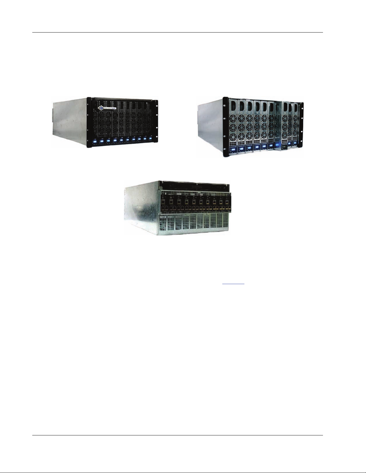
The picture below shows a rack containing A3100 chassis and A–Series blades.
on page 13
on page 25
ClearCube Technology, Inc. 7
Page 20
Chapter 1. A–Series Architecture and Product Overview
Chassis with Front Bezel and Rack Ears Front Bezel Removed
Rear of Chassis with
Expansion Backplane
The following figure shows an A3100 chassis with front bezel, rack ears, and expansion
backplane.
Figure 4. The A3100 chassis with front bezel, rack ears, and expansion backplane
The A3100 chassis contains an expansion backplane, a modular component that contains all
signal connectors and a chassis ID for A–Series blades. Figure 5
A3100 chassis and with an expansion backplane.
An A–Series blade connects to the expansion backplane when you insert and seat the blade in
an A3100 chassis. To connect power and Ethernet to a blade in an A3100 chassis, plug power
and Ethernet cables into the expansion backplane. The expansion backplane enables you to
remove the blade from the chassis without disconnecting any cables.
on page 9 shows detail of an
8 A–Series Setup and Installation Guide
Page 21

Cloud Desktops: Zero Clients and Thin Clients
Expansion
Backplane
A3100 ChassisAC Tray
The figure below shows the rear of an A3100 chassis with an expansion backplane attached.
Figure 5. Rear view of A3100 chassis with expansion backplane and AC tray
For more information, see
• “Chassis and Blade Power Requirements”
• “Chassis Expansion Backplane and Cabling”
• “Example Deployment Diagrams”
on page 18.
on page 15
on page 16, and
1.3 Cloud Desktops: Zero Clients and Thin Clients
ClearCube Cloud Desktops include zero clients using PCoIP technology and thin clients
(typically with embedded operating systems). Cloud Desktops connect to Blade PCs over a
standard Ethernet network. Zero clients and thin clients deliver video and peripheral signals to
a user from a Blade PC, allowing users to work over standard switched networks.
Cloud Desktops extend the ClearCube product line to let IT managers use their existing IP
network and cabling infrastructure, regardless of the distance between users' physical locations
and their centralized Blade PCs or other remote computing devices. ClearCube management
software—Sentral—enables IT administrators to manage assets and users, perform connection
brokering, and more.
For detailed instructions about setting up, using, and managing Cloud Desktops, see I/Port
User’s Guide. For information bout PCoIP technology, see PC-over-IP™ System User’s
Guide on the Support site at www.
ClearCube Technology, Inc. 9
clearcube.com/support/.
Page 22
Chapter 1. A–Series Architecture and Product Overview
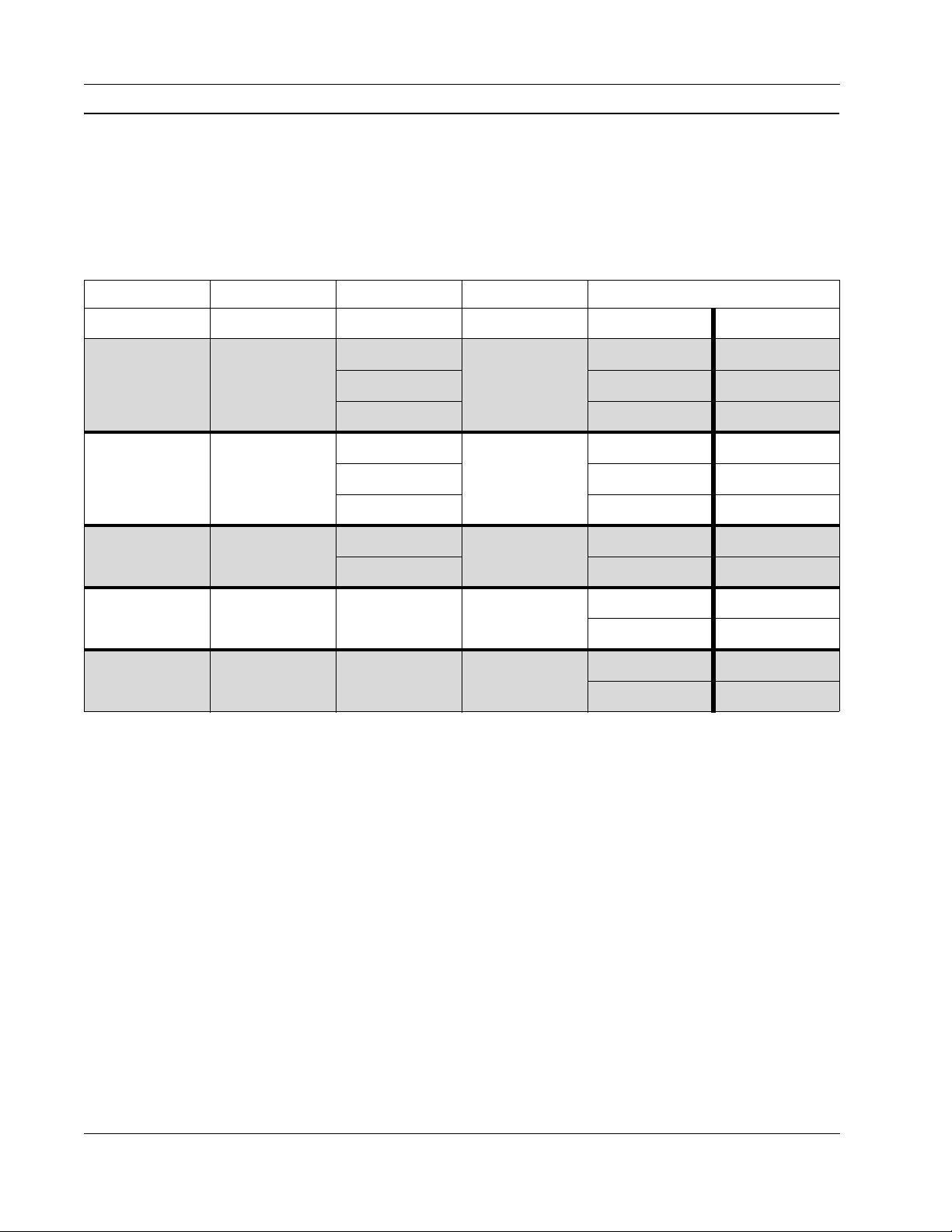
1.4 Monitor Support and Requirements
A–Series Blade PCs support up to four monitors. The table below shows GPU, host card, and
zero client combinations that provide the specified number of monitors and resolutions.
Various GPU and zero client options are available.
Table 1. Monitors, resolution, and device requirements
Monitors Resolution GPU Host Card Zero Client
Copper Fiber
Quadro 2000
1
2560 x 1600
Quadro 4000 CD9624 CD7624
V5422
NVS 310 — CD7822
Quadro 2000
2
1920 x 1200
Quadro 4000 CD9624 CD7624
V5422
NVS 310 — CD7822
Quadro 2000
2
2560 x 1600
V5442
Quadro 4000 CD9754
2
4
2560 x 1600
1920 x 1200
NVS 510 V5442
NVS 510 V5442
†.This model connects to displays using DisplayPort cables.
CD9622 CD7622
CD9622 CD7622
CD9752
†
†
CD7752
CD7754
CD9642 CD7642
CD9644 CD7644
CD9642 CD7642
CD9644 CD7644
†
†
10 A–Series Setup and Installation Guide
Page 23

Chapter 2. Site Preparation and Network
Planning
This chapter describes preliminary steps to take after receiving your A–Series shipment, and
describes the hardware and environmental requirements for your A–Series products. The
following list identifies each of the topics discussed in this chapter.
• “About Your Shipment”
• “Rack and Cabinet Requirements”
• “Space and Floor Support”
• “Cooling and Airflow”
• “Chassis and Blade Power Requirements”
• “Chassis Expansion Backplane and Cabling”
on this page
on page 14
on page 14
2.1 About Your Shipment
This section details precautions to follow before unpacking your shipment and the order in
which to unpack each device in your shipment.
2.1.1 Inspecting Your Shipment and Devices
on page 13
on page 15
on page 16
Examine the outside of all containers in your shipment before opening them.
If you find any external damage to the containers that yo u receive, do not open them.
NOTE
A–Series Setup and Installation Guide 11
Notify the shipper that damage has occurred and request that they inspect the
containers before you unpack them.
Page 24
Chapter 2. Site Preparation a nd Net work Planning
If you discover damaged devices after unpacking your shipment:
• Contact the shipper to notify them of the damage.
• Contact ClearCube Support for a replacement. For information about contacting Support,
see Appendix C. “Support”
CAUTION: Do not use a Blade PC that shows any sign of damage. Using a
damaged blade can cause extensive damage.
2.1.2 Unpacking Your Shipment
ClearCube components are typically shipped in separate containers. The following list
describes the components shipped for typical installations and specifies the order in which you
should unpack your shipment.
on page 61.
NOTE
To protect ClearCube devices, keep them in their shipping containers until you
install, insert, or connect the devices.
1. Chassis—Only unpack before attaching to a previously-installed rack or cabinet.
2. Blade PCs—Only unpack before inserting in an A–Series chassis.
3. Zero client and thin client—Only unpack before connecting to a Blade PC. Cloud
Desktops (zero clients and thin clients) are shipped with or without power supplies and
keyboards, depending on the devices that you use in your environment. See the
documentation included with your zero clients or thin clients for instructions about setting
up, configuring, and using them.
Save shipping containers and packing materials at least until your ClearCube
NOTE
See “Installing an A–Series Chassis”
installing chassis. See “Installing Blade PC in a Chassis”
installation is complete and tested. Use shipping containers for RMAs (see "Return
Merchandise Authorization (RMA)" on page 61 for more information).
on page 21 for instructions about unpacking and
on page 38 for instructions about
installing blades.
12 A–Series Setup and Installation Guide
Page 25
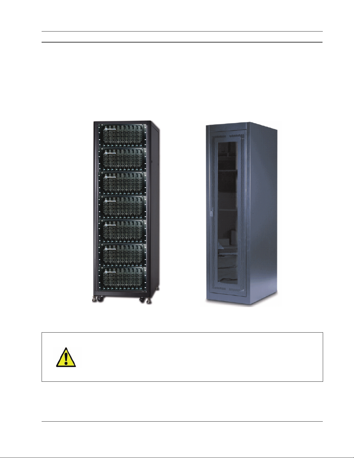
2.2 Rack and Cabinet Requirements
Rack Cabinet
Before installing ClearCube components, it is important to properly prepare the site where you
will install the chassis and Blade PCs. This section explains how to plan for cabinet, rack and
chassis installation. The pictures below show two options for holding ClearCube chassis. A
standard 42U rack or cabinet can hold as many as seven A3100 chassis.
Rack and Cabinet Requirements
Figure 6. A fully-loaded rack with A3100 chassis and a standard 19-inch cabinet
CAUTION: Equipment racks and cabinets can become highly unsta ble if not
adequately secured. Read and follow the manufacturer's specifications and
recommendations for mounting. Additional ClearCube guidelines are
provided throughout this section that—with the manufacturer's
requirements—will ensure a safe installation.
Fully-enclosed electrical cabinets are the preferred option for mounting your ClearCube
chassis. When using cabinets, make sure that:
ClearCube Technology, Inc. 13
Page 26
Chapter 2. Site Preparation a nd Net work Planning
• Front and rear panels and doors are vented to provide sufficient airflow for intake and
exhaust.
• Ensure that you have at least 34 inches (86 cm) of interior depth measured from the front
of the unit to accommodate the cabling that exits from the rear of the chassis.
• Provide adequate space at the back of the rack or cabinet to allow servicing the cables and
equipment.
You can fit cabinets with casters to improve mobility and to ease access when servicing.
WARNING: When installing chassis in a cabinet enclosure, never use only
one set of mounting brackets at the front. Select a cabinet tha t has an
adjustable center rail or rear rail in addition to the front rail. ClearCube's
adjustable mounting kit is required to attach the chassis to both the front
and center/rear rails.
2.2.1 Space and Floor Support
Before installing racks, chassis, and blades, verify that your rack and floor can support the
weight of a fully-loaded rack. If your initial installation contains fewer than seven chassis,
ensure that your rack and floor can support the weight of a fully-loaded rack so you can add
additional blades and chassis in the future. If you are installing other equipment in the rack or
cabinet, take this additional weight into consideration.
Seven fully-loaded chassis (including expansion backplanes) weigh approximately 1347.5
pounds (612 kilograms), not including any cabling. One 42U rack can hold up to seven
chassis, creating a load of greater than 225 pounds per square foot (1099 kilograms per square
meter) for each of the roughly 6 square feet (0.56 square meters) of floor space required for
each rack.
NOTE
When planning for the space required in your data center, include 36 inches in front
of each cabinet to provide adequate room when your remove blades from chassis.
WARNING: Improper structural support could cause the rack or cabinet to lean
and cause the floor to buckle and potentially case structural damage.
2.2.2 Cooling and Airflow
The following sections detail items to consider when addressing cooling and airflow for
A3100 chassis.
A–Series chassis draw cool air (25 degrees Celsius) in through the front of the chassis, and
exhausts it out the back.
14 A–Series Setup and Installation Guide
Page 27

Chassis and Blade Power Requirements
• Ensure that the air conditioning and ventilation system for the installation area can
accommodate your installation’s thermal load. Contact ClearCube Support for detailed
power and cooling requirements tables.
• The rear of the chassis has air vents for Blade PC fans. The fan openings must be at least
five inches from any airflow-impeding barriers such as walls, the rear of the rack door or
panel, large bundles of cables, and so on. The availability of an air exit path from these
fans is imperative for the efficient operation of units. Failure to provide sufficient air
venting will result in a thermal overload of Blade PCs. If the chassis is installed in a
cabinet, use a fully vented rear door or panel.
CAUTION: Failure to provide sufficient space and room ventilation will
result in overheating that can cause eventual unit failure not covere d as
part of unit warranty.
• Each chassis produces varying amounts of heat, depending on processor activity. Contact
ClearCube Support for detailed power and cooling requirements tables. See
Appendix C. “Support”
on page 61 for information about contacting ClearCube Support.
2.3 Chassis and Blade Power Requirements
Your ClearCube system centralizes computing components in a single location, which
centralizes power requirements in one area. Although the ClearCube solution reduces the
overall power required when compared to traditional PCs, the power demands in the IT center
are increased. Use the power and current specifications in this section and in the power and
cooling requirements documentation available on the ClearCube Support site to ensure that
your facilities can provide the required power safely without tripping circuit breakers.
2.3.1 Power Input Considerations
A3100 chassis hold up to 10 blades and have four A/C power inputs (two inputs for each half
of the chassis). For each half of the chassis, one input powers the blades in that half (blades 1
to 5 or blades 6 to 10) and the other input is a redundant backup.
• You must connect both powers cords to the chassis for failover power.
• The maximum steady-state current draw of a single fully loaded chassis ranges between 7
and 12 amps at 120 VAC per input, based on the level of user activity.
• Peak initial current draw of a fully-populated chassis is 16.3 amps at 120 VAC per input.
See ClearCube Support for detailed power and cooling requirements tables. See
Appendix C. “Support”
on page 61 for information about contacting ClearCube Support.
ClearCube Technology, Inc. 15
Page 28

Chapter 2. Site Preparation a nd Net work Planning
2.3.2 Power Circuit Considerations
If you are putting multiple chassis on a single power circuit, ensure that the circuit can safely
handle the combined peak currents of the chassis.
peak current, you must have additional power system capacity installed by a qualified electrician.
CAUTION: Make sure your power strips, power grid, and circuit breakers can
safely provide the required current. Ensure that any extension cords used
meet local safety regulations and local fire codes.
Contact ClearCube for detailed power and cooling requirements tables. See
Appendix C. “Support”
on page 61 for information about contacting ClearCube Support.
If your existing power circuit cannot handle the
2.4 Chassis Expansion Backplane and Cabling
This section shows
• expansion backplane network ports and features
• maximum number of Ethernet cables the expansion backplane supports
• supported cable types for A–Series blades and chassis.
2.4.1 Chassis Ports and Supported Protocols
Network ports on the A3100 expansion backplane (on the rear of the chassis, shown in the
pictures below) support various network functions and protocols. All ports are standard RJ45
Ethernet ports. The list below shows each network port on the expansion backplane, shows the
protocols each supports, and notes any blade model differences.
PCoIP
Primary
Secondary
• PCoIP Port — This port is dedicated to all PCoIP traffic
from the PCoIP host card in an A–Series blade.
• Pri (Primary Port) — This port is for standard network
traffic.
• Sec (Secondary Port) — This port is for standard
network traffic for A6106D blades. A6105D blades do
not support the secondary port.
16 A–Series Setup and Installation Guide
Page 29

Chassis Expansion Backplane and Cabling
Ethernet Dedicated
PCoIP
Ethernet
A3100 Chassis
and
Expansion Backplane
A6106D Blade
Ethernet Dedicated
PCoIP
Unsupported
A6105D Blade
The picture below shows the rear of the A3100 chassis and expansion backplane port
assignments for A6106D and A6105D blades.
Figure 7. A3100 chassis expansion backplane with A6106D and A6105D blades
2.4.2 Ethernet Cable Requirements
The table below shows, for each blade model, the
• purpose and number of Ethernet cables, and
• the total number of Ethernet cables for each blade model and for a fully-populated chassis.
Table 2. The number of Ethernet cables by Blade PC model and for fully-loaded chassis
Purpose of Cable or Total A6106D Blade PC A6105D Blade PC
PCoIP cable
Primary
Network Adapter cable
Secondary
Network Adapter cable
Total cables for each Blade PC
Maximum cables for each chassis
11
11
1 Not supported
32
30 20
ClearCube Technology, Inc. 17
Page 30

Chapter 2. Site Preparation a nd Net work Planning
2.4.3 Supported Cables
The A3100 chassis uses standard network cables with RJ-45 connectors to connect to Ethernet
networks. The list below shows supported network cable types:
•CAT5
•CAT5e
•CAT6
•CAT6e
Network connections follow standard Ethernet guidelines.
2.5 Example Deployment Diagrams
Each fully-loaded chassis requires up to 30 network cables (depending on blade model and
deployment type) for connections to network hubs or switches (see “Chassis Ports and
Supported Protocols” on page 16 for more information).
18 A–Series Setup and Installation Guide
Page 31

Example Deployment Diagrams
2.5.1 Dedicated PCoIP Network
The picture below is a high-level diagram of a deployment where PCoIP host cards and zero
clients are optimized by isolating PCoIP traffic on a dedicated PCoIP network (using physical
or virtual LANs).
Figure 8. A–Series deployment optimized by isolating PCoIP traffic
ClearCube Technology, Inc. 19
Page 32

Chapter 2. Site Preparation a nd Net work Planning
2.5.2 Shared Network
The picture below is a high-level diagram of a deployment where PCoIP traffic (from host
cards and zero clients) and regular network traffic is on the same network.
NOTE
To optimize PCoIP traffic, ClearCube recommends using dedic at ed net wo rks
(physical or virtual LANs) as shown above.
Figure 9. A–Series deployment with shared PCoIP and regular network traffic
20 A–Series Setup and Installation Guide
Page 33

Chapter 3. Chassis and Blade PC
Installation
Installing ClearCube products is a series of simple tasks that you can perform in a short
amount of time. The following instructions are intended for IT technicians who are familiar
with computer systems and familiar with configuring hardware. This chapter discusses the
following topics:
• “Tools for Installation”
• “Installing an A–Series Chassis”
• “Installing Blade PC in a Chassis”
on this page
on this page
on page 38
3.1 Tools for Installation
You can perform all installation tasks with the following tools:
• #2 Phillips screwdriver—Required.
• 1/4–inch nut driver with magnetic tip—Optional. Suggested for removing and replacing
the self-tapping sheet metal screws located on the A3100 chassis.
3.2 Installing an A–Series Chassis
Mount your A–Series chassis on a standard, 19-inch rack or cabinet to hold your A–Series
blades. The following list describes the chassis components.
• Front Bezel—A removable bezel at the front of the chassis that protects blades and
provides labels for buttons and indicators.
A–Series Setup and Installation Guide 21
Page 34

Chapter 3. Chassis and Blade PC Installation
• Expansion backplane—Provides signal connectors for Blade PCs.
This modular component might be shipped separately from your chassis. If the
NOTE
expansion backplane is not included in your A3100 chassis, see "Attaching and
Removing the Expansion Backplane" on page 28 for instructions about how to
insert the expansion backplane.
The following sections describe:
• The contents of your chassis shipment container. See “Chassis Container Contents”
on this
page for more information.
• How to mount a chassis. See “Mounting A–Series Chassis”
on page 23 for more
information.
The following sections assume that you already have appropriate blade racks, cabinets, or both
correctly installed with adequate space for the chassis you are mounting.
3.2.1 Chassis Container Contents
The list below shows how to unpack your A–Series chassis container.
1. Open the chassis box.
2. Remove the packing material
3. Remove the chassis and set it on a flat working surface.
4. Check the chassis for any visible damage. If you find any product damage, immediately
contact the shipper for an on-site inspection.
A–Series chassis are shipped with the following items:
• Chassis—AC power cords are shipped in a separate container, as described in “Chassis
AC Power Cords” on page 23.
• Quick Start Guide—Briefly describes how to install the chassis and how to install blades
in the chassis.
• Chassis accessory kit—Allows universal mounting in standard, 19-inch racks or cabinets.
The chassis accessory kit includes the following:
– Four rack-mount brackets
– Chassis ground strap and mounting hardware
– Mounting h ardware
See "Using a Chassis Rapid–Mount Kit"
22 A–Series Setup and Installation Guide
on page 25 for information about mounting a kit.
Page 35

Installing an A–Series Chassis
3.2.2 Chassis AC Power Cords
Chassis AC power cords are shipped in different containers than A–Series chassis. Only use
power cords included with your shipment. Chassis shipped to countries with a:
• 100–130-volt power system use power cords rated at 15 amps
• 250-volt power system use power cords rated at 10 amps
• 250-volt power system use power cords rated at 13 amps
3.2.3 Mounting A–Series Chassis
Mount your A–Series chassis to a four-post rack or cabinet using the kit you purchased. The
list below shows each kit.
• Chassis accessory kit— Included with each A–Series chassis. The kit fits all standard,
four-post, 19-inch racks and includes front and back mounting brackets and all necessary
hardware. See “Using a Chassis Accessory Kit”
the kit.
on page 24 for instructions about using
—OR—
• Chassis rapid-mount kit—Compatible with racks and cabinets with four posts and
square mounting holes for snap-in rack nuts. Not all third-party racks are compatible with
the chassis rapid–mount kit. See “Using a Chassis Rapid–Mount Kit”
instructions about using the kit.
NOTE A–Series chassis do not support two-post enclosures.
Before mounting your chassis, ensure that you have the tools listed in “Tools for Installation”
on page 21.
CAUTION: To avoid equipment damage and potentia l personal injury, install
the chassis without blades installed.
on page 25 for
3.2.3.1 Cabinet Mounting Considerations
A–Series chassis draw cool air in through the front of the chassis and exhausts it out the back.
If you mount your A–Series chassis in a cabinet-style enclosure, ensure that:
• There is at least 34 inches (86 cm) of interior depth measured from the front of the
enclosure to accommodate the cabling and air flow that exits from the rear of each chassis.
• If the cabinet enclosure front doors are not vented, add an additional 4 inches (11 cm) in
front of the chassis for proper airflow.
• The spacing between the front and back rails is no more than 30 inches (76 cm).
ClearCube Technology, Inc. 23
Page 36
Chapter 3. Chassis and Blade PC Installation
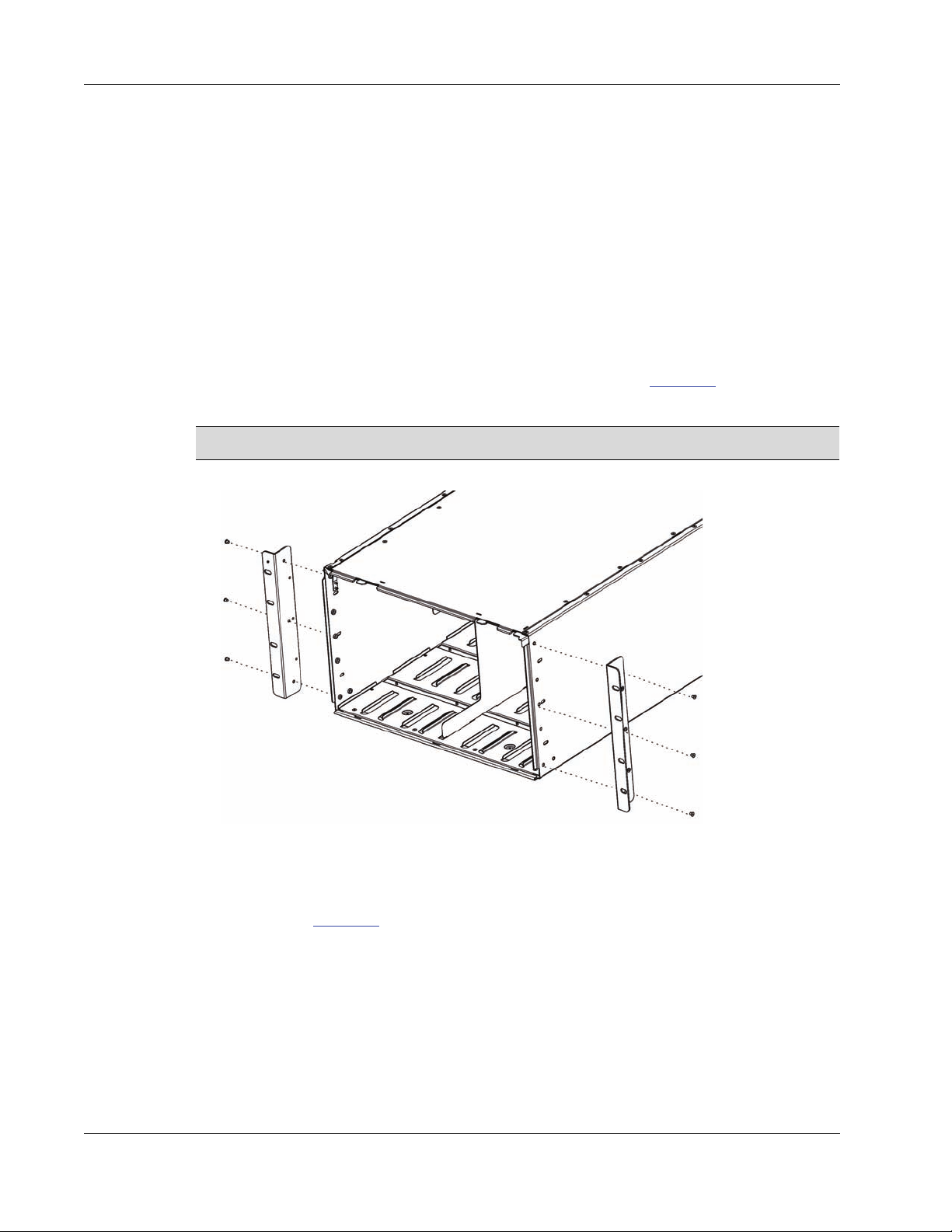
3.2.3.2 Using a Chassis Accessory Kit
Using the brackets and hardware included in your kit, you can install an A–Series chassis from
the front or from the rear of the rack.
To install a chassis using the chassis accessory kit, perform the following steps.
1. When installing in a cabinet enclosure, loosely attach the adjustable rear mounting
brackets to the chassis with three screws on each side.
2. Position the chassis in the cabinet so that the front of the chassis lines up with the front rail
and then slide the adjustable rear brackets into place. Tighten the screws that hold the rear
brackets in place.
3. With the rear brackets firmly attached to the chassis, slide the chassis into the cabinet from
the rear. Open the front bezel of the chassis (latch is shown in Figure 20
then attach the front brackets with three screws on each side.
NOTE You can attach front brackets from the inside or from the outside of the chassis.
on page 38) and
Figure 10. Attaching front brackets
4. Using th e hardware provided with your cabinet, attach the chassis mounting brackets to
the cabinet rails.
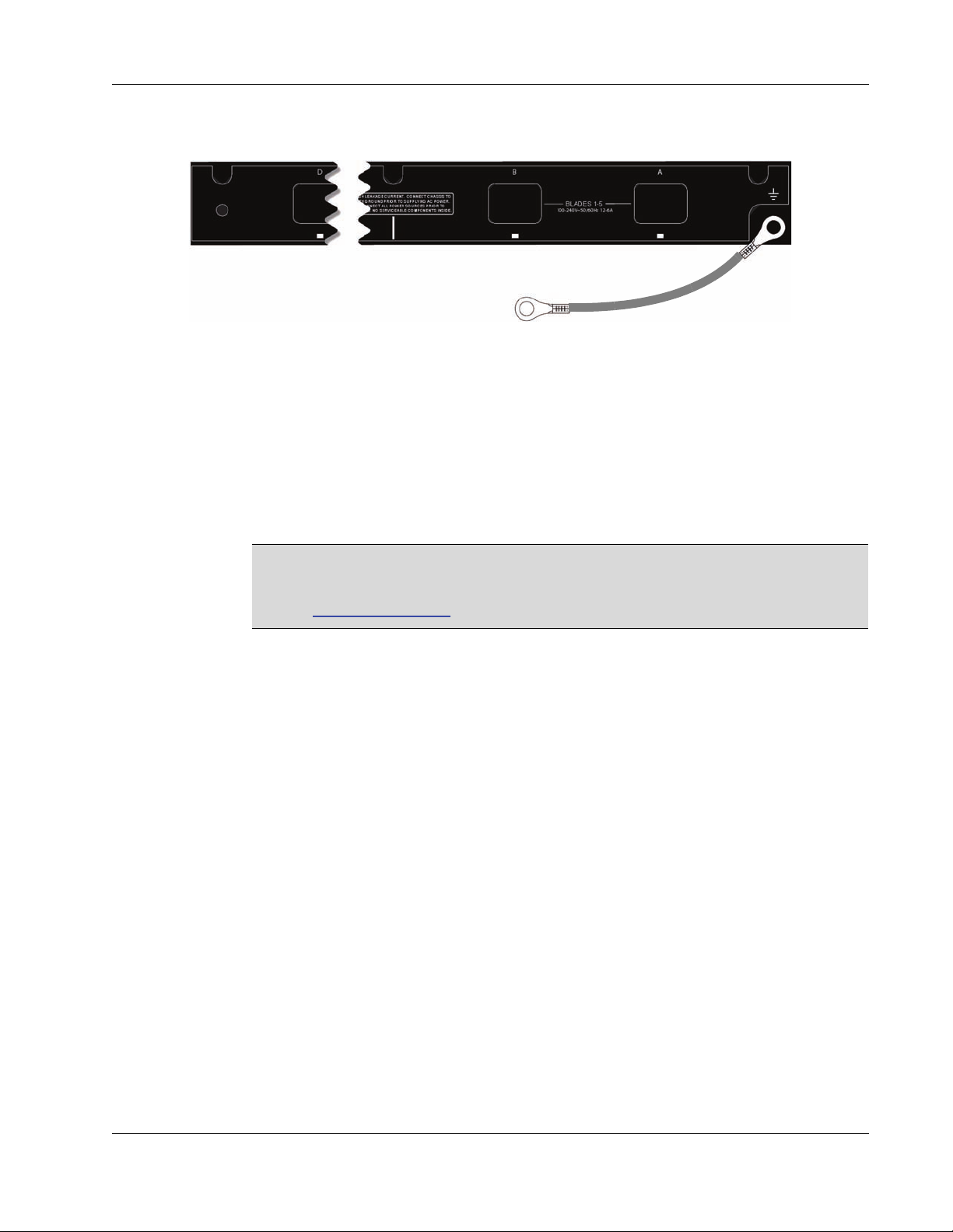
5. As shown in Figure 11
below, attach one end of the ground strap (included with the
chassis) to the chassis and attach the other end to the rack frame with the two 10-32 screws
24 A–Series Setup and Installation Guide
Page 37
Installing an A–Series Chassis
Attach End to Rack Frame
supplied in your shipment. Obtain a cage nut to attach the strap to your cage. Ensure that
the rack is properly grounded.
Figure 11. Chassis ground strap attached to the Dual Input Module (located above the expansion backplane)
g
6. Supply power to the chassis.
a. Attach the AC power cords included with the chassis to the rear panel power
connectors on the chassis.
b. Connect the AC power cords to a surge-protected power source such as an
uninterruptible power supply (UPS) or power strip. Use the cable retention clamps
(included with your chassis) to secure the power cables.
ClearCube products shipped to countries using 100-130-volt power systems
NOTE
include power cords rated at 15 amps. ClearCube products shipped to countries
using 208-240-volt power systems include power cords rated at 10 amps. See
"Safety Guidelines"
on page x for more information.
Ensure that all rooms or data centers in which you install Blade PCs are clean before you begin
installing blades. ClearCube recommends completing all additional chassis hardware
installation and preliminary network cabling for zero clients and thin clients (if applicable)
before you begin installing any Blade PCs.
3.2.3.3 Using a Chassis Rapid–Mount Kit
The chassis rapid–mount kit is compatible with most four-post racks and cabinets. To install a
chassis with the chassis rapid–mount kit, perform the following steps.
1. Ensure that you:
– Install your chassis from the front of the rack or cabinet.
– Begin installing chassis at the bottom of the rack or cabinet to provide support for
each chassis before it is securely mounted. This simplifies getting the chassis square
and level in the rack.
2. Unscrew the thumbscrew holding each pair of chassis and rack brackets together, and then
slide the brackets apart.
– The bracket co ntaining springs is the rack bracket and is installed on the rack.
– The solid bracket is the chassis bracket, and it is screwed to the chassis.
3. Remove the front rack ears that are currently on the A3100 chassis.
ClearCube Technology, Inc. 25
Page 38
Chapter 3. Chassis and Blade PC Installation
Locking Latch
Main Bracket Finger Handle
Spring Slider
Flanges
Slider (Back)
Rack Ears
Front Rack Ears
Slider Ears Inserted
in Rear Post
Front Ears
Inserted in Front Post
4. Mount the chassis bracket to the chassis with four flathead screws included in your kit.
Repeat on the other side of the chassis.
NOTE
You can use the chassis and rack brackets on either side of your rack or cabinet;
that is, the brackets are not specific to either side of your enclosure.
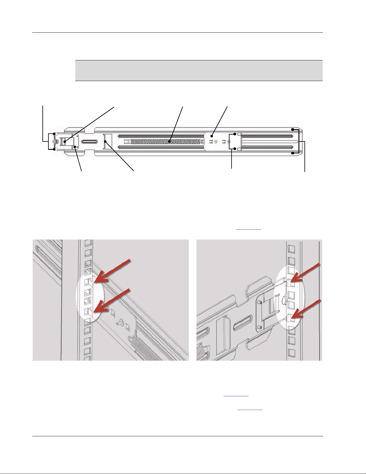
Figure 12. Rack bracket for chassis rapid–mount kit
5. Determine the location and holes to use to mount the rack ears on the rack bracket. A
guide is provided with the chassis rapid–mount kit.
6. Insert the slider rack ears, as shown in the left portion of Figure 13
on this page, in the
back side of the rear rack post.
26 A–Series Setup and Installation Guide
7. Pull the rack bracket forward and insert the front rack ears into holes on the front side of
the front post, as shown in the right-hand portion of Figure 13
Figure 13. Rack bracket attachment points
8. Push forward on the ears until the locking latch, shown in Figure 12
on this page.
on page 26, snaps and
locks into place. To ensure that the bracket is level, check that you placed the front and
rear ends of the bracket in corresponding holes on the front and rear post. If you need to
Page 39

Installing an A–Series Chassis
reposition the brackets, remove them as described in “Removing a Rapid–Mount Kit
Bracket” on this page.
9. With the other rapid–mount kit bracket, repeat steps
4 through 6 on the opposite side of
the rack, ensuring that the bracket is in the appropriate, mirrored orientation. Ensure that
the brackets are level with each other.
10. Slide the chassis and brackets onto the rack brackets from the front. Ensure the U channels
on the chassis bracket engage the flanges on the rack bracket.
11. Slide the chassis all the way onto the rack brackets until flush with the front of the rack
and tighten the thumb screws.
12. Attach the ground strap provided with each chassis to the chassis and to the rack, and
ensure that the rack is properly grounded. Use a 10-32 screw and cage nut (not included)
to attach the strap to your cage.
CAUTION: High Leakage Current. Connect chassis earth ground before
supplying AC power to the chassis.
13. Supply power to the chassis (see “Chassis Power and Failover Power Feature”
on page 30
for information about the chassis failover power feature).
a. Attach the AC power cords included with the chassis to the power connectors on the
chassis AC tray (see Figure 14
on page 28).
b. Connect the AC power cords to a surge-protected power source such as an
uninterruptible power supply (UPS) or power strip, and use the cable retention clamps
to secure the power cables.
ClearCube products shipped to countries using 100–130-volt p ower systems include
NOTE
power cords rated at 15 amps. ClearCube products shipped to countries using
208–240-volt power systems include power cords rated at 10 amps. See "Safety
Guidelines" on page x for more information.
Ensure that all rooms or data centers in which you install Blade PCs are clean before you begin
installing blades. ClearCube recommends completing all additional chassis hardware
installation and preliminary network cabling for Cloud Desktops before you begin installing
any Blade PCs.
3.2.3.4 Removing a Rapid–Mount Kit Bracket
To remove a rapid–mount kit bracket (shown in Figure 13 on page 26), perform the steps
below.
1. Use your finger to pull the finger tab on the front of the bracket toward the rear of the
bracket.
2. Slide the ears forward and remove the bracket. Repeat on the other side.
ClearCube Technology, Inc. 27
Page 40

Chapter 3. Chassis and Blade PC Installation
Expansion
Backplane
A3100 Chassis
AC Tray
3.2.4 Attaching and Removing the Expansion Backplane
This section describes how to attach and remove the expansion backplane from the A3100
chassis. The following figure shows the rear of an A3100 chassis with an expansion backplane
attached.
Figure 14. Rear view of A3100 chassis with expansion backplane
The expansion backplane contains all signal connectors and an electronic asset tag for the
A3100 chassis.
3.2.4.1 Attaching the Expansion Backplane
Perform the following steps to attach the expansion backplane to an A3100 chassis.
1. Ensure that no AC power cords are connected to the chassis. If any AC power cords are
connected, remove them.
2. From the rear of the chassis, insert the hooks on each side of the expansion backplane into
the slots on each side of the chassis, then gently lower the backplane until it rests on the
28 A–Series Setup and Installation Guide
Page 41

Installing an A–Series Chassis
Expansion
Backplane Hooks
Chassis Slots for
Hooks
chassis. The following figure shows the backplane hooks and the corresponding slots on
the chassis.
Figure 15. Attaching the expansion backplane to a chassis
3. Insert the screws included in your kit into the flanges on the bottom edge of the backplane. Use
a #2 Phillips screwdriver to screw both screws into the chassis, as shown below.
Figure 16. Location of screws on the bottom edge of the expansion backplane
Connect power to the chassis, as described in “Chassis Power and Failover Power Feature”
below, to complete your chassis installation.
3.2.4.2 Removing the Expansion Backplane
Perform the following steps to remove the expansion backplane from an A3100 chassis.
1. Ensure that you disconnect all AC power cords from the chassis.
2. Use a #2 Phillips screwdriver to remove both screws from the flanges on the bottom edge
of the expansion backplane. Figure 16
3. Gently lift the expansion backplane straight up to remove the hooks on each side of the
backplane from the slots on the chassis.
ClearCube Technology, Inc. 29
above shows the location of the screws.
Page 42

Chapter 3. Chassis and Blade PC Installation
Power Receptacles for
Blades 6 to 10
Power Receptacles
for Blades 1 to 5
ABCD
3.2.5 Chassis Power and Failover Power Feature
As shown in the following figure, the A3100 chassis has four power receptacles: two for each
half of the chassis providing power and redundant power.
Figure 17. The A3100 chassis power receptacles
To ensure the most reliable operation of the A3100 chassis, ClearCube recommends that all
chassis power sources are connected to an uninterruptible power supply (UPS).
If excessive power surges or voltage spikes damage the failover power feature, the
NOTE
damage might not be externally evident. Regulating, uninterruptible power supplies
can protect the A3100 from surges and spikes.
The A3100 chassis has four power receptacles:
• Receptacles A and B power blades in slots one through five (one receptacle provides
redundant power when both receptacles are populated—see sections below).
• Receptacles C and D power blades in slots six through ten (one receptacle provides
redundant power when both receptacles are populated—see sections below).
Dual receptacles for each half of the chassis provide failover power for each set of blades.
Power indicator LEDs are below each power receptacle. LEDs are illuminated when
receptacles receive power.
ClearCube recommends the following power configurations.
3.2.5.1 To Enable Chassis Failover Power Feature
Connect power to all power inputs.
• Receptacles A and C provide primary power.
• Receptacles B and D provide failover power. ClearCube recommends connecting the
cords in receptacles B and D to a backup power supply, such as a different power circuit or
to a UPS.
30 A–Series Setup and Installation Guide
Page 43

Configuring A–Series Blade PCs before Installation
3.2.5.2 To Power Chassis without Failover Power Feature
To power a chassis using primary power only (without the failover power feature), connect
power cords to receptacles B and D.
For the most reliable power configuration use the failover power feature, where
NOTE
If only one power cord is connected to an A–Series chassis, only the side of the chassis that is
connected to power will supply power to blades. Only use AC power cords supplied with the
chassis. See Appendix C. “Support”
Support to obtain replacement power cords.
NOTE
power receptacles A and C are powered by a different power source than
receptacles B and D.
on page 61 for information about contacting ClearCube
Based on the level of user activity, the maximum steady-state current draw of a single,
fully-loaded chassis ranges between 7 and 12 amps at 120 VAC on each side of the
chassis (that is, on each power supply). The peak initial current draw is 16 amps on
each input. If you place multiple chassis on a single power circuit, ensure that the
circuit can safely handle the combined currents of all the equipment on the circuit.
Contact ClearCube Support for detailed power and cooling requirements tables.
CAUTION: Ensure that your power strips, power grid, and circuit breakers
can safely provide the required current. Ensure that any extension cords
used meet local safety regulations and fire codes. Use peak current draws
when specifying uninterruptible power supply (UPS) capacity.
Contact ClearCube Support for detailed power and cooling requirements tables. See
Appendix C. “Support”
on page 61 for contact information.
3.3 Configuring A–Series Blade PCs before Installation
The sections below show how to configure A–Series Blade PCs.
3.3.1 Viewing Pre-OS Video (BIOS and Network Boot, PXE Boot)
This section describes how to view video output (such as power-on self test [POST] codes and
BIOS configuration utility screens) generated before a blade or VM operating system starts.
ClearCube Technology, Inc. 31
Page 44

Chapter 3. Chassis and Blade PC Installation
3.3.1.1 Before You Begin
Be sure to have the following:
• a switch connected to a DHCP network
• a Blade PC and a standard computer power cable appropriate for your region (such as a
120 V, IEC 60320 C13 connector with NEMA 5-15 inlet)
• a ClearCube zero client compatible with the blade’s video configuration (a dual zero client
for a dual host card or a quad zero client for a quad host card). The blade’s video
configuration is specified on a label on the side of the blade (shown in Figure 3
• a zero client power supply
• a monitor, appropriate video cable, and power cable
• a USB keyboard and a mouse, and
• two Ethernet cables.
These instructions assume that devices are connected to an imaging network or
other network with a DHCP server to provide IP addresses for the blade's PCoIP
host card and for the zero client. MAC addresses are specified on labels on the side
NOTE
of the blade and on the zero client. To identify the blade host card to connect to from
the zero client, you might need to consult DHCP tables. DHCP tables should show
each device's MAC address and the corresponding IP address assigned to the host
card and to the zero client.
on page 5).
3.3.1.2 Connecting Devices
The list below shows how to connect devices to view pre-OS video.
1. Remove the Blade PC from the chassis as described in “Removing Blade PC from a
Chassis” on page 39. Place the blade on a stable surface, such as a bench or on the top of a
desk.
2. Connect a USB keyboard to a port on the top of the blade. (Ensu re that you do not
disconnect the Ethernet cable that might be visible from this opening.)
3. Connect monitors to the zero client as described below.
NOTE
4. Connect the blade and the zero client to your network:
Connect a monitor to a zero client as described below. Do not connect a monitor
to a video port on the top of the blade.
32 A–Series Setup and Installation Guide
Page 45

Configuring A–Series Blade PCs before Installation
a. Connect an Ethernet cable to the blade's dedicated PCoIP port (the right-most port
on the rear of the blade). Connect the other end of the cable to a switch connected to
your network.
Figure 18. The dedicated PCoIP port on the rear of the blade
b. Conn ect the zero client to the same switch.
c. Optionally, if you are imaging the blade, connect an Ethernet cable to the left-most
LAN port on the rear of the blade and connect the other end of the cable to the switch
(see “Custom Operating System Requirements”
on page 35 for information about
system image requirements).
Figure 19. The LAN port on the rear of the blade
5. Conn ect the monitor and a mouse to the zero client.
6. Conn ect the power adapter to the zero client and then plug the cord into a power outlet.
Next steps: power on blade, create a PCoIP session, and view pre-OS video.
3.3.1.3 Create Session and View Video
The steps below show how to create a PCoIP session to view pre-OS video.
1. Connect a power cable to the external power connector at the rear of the blade and then
plug the cable into a power outlet.
ClearCube Technology, Inc. 33
Page 46

Chapter 3. Chassis and Blade PC Installation
2. Press the power button on the front of the blade to power it on, and then press the power
button on the front of the zero client to power it on.
3. From the monitors connected to the zero client, click the Connect button. After several
moments, the zero client will identify host cards to which it can connect. The zero client
on-screen display (OSD) displays one or more host card IP addresses and their
corresponding MAC addresses.
The video host card MAC address is shown on a label on the side of the Blade
NOTE
PC. The zero client MAC address is on a label on the rear or bottom of the zero
client.
4. Select the blade's host card from the list and click OK.
Result: The zero client connects to the Blade PC’s host card and displays the des kto p.
5. From the operating system, restart the Blade PC.
Result: The operating system displays shutdown messages and the screen goes bl ank.
6. Watch the keyboard lights. As soon as they blink or illuminate, press the F2 key
repeatedly for about 10 seconds.
Result: Pre-OS video is displayed.
7. After performing configuration steps, power off both devices. Remove the Blade PC and
zero client power cables from the power outlets and then remove the cables from each
device.
8. Remove peripherals from both devices.
9. Replace the blade in the chassis as shown in “Removing Blade PC from a Chassis”
on
page 39.
Next steps: You can now deploy your A–Series blade.
3.3.2 Operating System Images
The following sections describe how to:
• Install a customized operating system image on an A–Series Blade PC
• Prepare the default operating system image before deploying an A–Series blade
34 A–Series Setup and Installation Guide
Page 47

Configuring A–Series Blade PCs before Installation
3.3.2.1 Using the Default Operating System Image
If your blades were purchased with Windows operating systems, you must complete the
Windows Out of Box Experience (OOBE) on each blade. The steps below show how to
connect to a blade and complete OOBE.
NOTE
1. Complete the steps shown in sections “Before You Begin”
With one exception, the steps shown below are shown in previous sections. Be sure
to note the exception in the steps below.
on page 32 and in “Connecting
Devices” on page 32.
2. Begin the procedure shown in “Create Session and View Video”
reach step
4, select the blade’s host card and click OK. After a moment you are connected
on page 33. When you
to the blade, where you can view and complete OOBE.
3. Accept the operating system license and specify a name for the blade.
After the operating system initial configuration is complete, the blade boots to the operating
system. You can now deploy the blade.
3.3.2.2 Custom Operating System Requirements
If you are re-imaging a ClearCube blade or are installing a custom image on a blade, note that
your blades require specific firmware, motherboard chipset drivers, device drivers, and more.
ClearCube devices do not necessarily support every driver o r firmware that vendors
NOTE
provide. To ensure that your devices support drivers and firmware, only use drivers
and firmware obtained from ClearCube.
The following procedure details steps and items required when creating and configuring
operating systems for ClearCube blades, and it assumes you are using Windows
®
7 operating
system. The menu options specified here might be different in other Windows operating
systems.
Before you begin
Be sure to have the following:
• a switch connected to a DHCP network
• a Blade PC and standard computer power cable appropriate for your region (such as a 120 V,
IEC 60320 C13 connector with NEMA 5-15 inlet)
• a ClearCube zero client compatible with the blade’s video configuration (a dual zero client
for a dual host card or a quad zero client for a quad host card). The blade’s video
configuration is specified on a label on the side of the blade (shown in Figure 3
on page 5).
• a zero client power supply
• a monitor, appropriate video cable, and power cable
ClearCube Technology, Inc. 35
Page 48

Chapter 3. Chassis and Blade PC Installation
• a USB keyboard and a mouse, and
• two Ethernet cables.
These instructions assume that devices are connected to an imaging network or
other network with a DHCP server to provide IP addresses for the blade's PCoIP
host card and for the zero client. MAC addresses are specified on labels on the side
NOTE
of the blade and on the zero client. To identify the blade host card to connect to from
the zero client, you might need to consult DHCP tables. DHCP tables should show
each device's MAC address and the corresponding IP address assigned to the host
card and to the zero client.
1. Ensure that yo u obtain drivers for your blade or VM from the ClearCube Support site at
http://www.clearcube.com/support/
available on the Support site.
2. Connect to the blade you are imaging as described in “Viewing Pre-OS Video (BIOS and
Network Boot, PXE Boot)” on page 31. When you reach step 4 in “Create Session and
View Video” on page 33:
– follow the step as shown to view pre-boot options
. All drivers and downloads cited in this procedure are
—OR—
– if an operating system is already installed, select the blade’s host card and click OK.
3. Install a supported operating system. See Appendix A. “Specifications”
on page 55 for
supported operating systems.
4. Install the Intel chipset driver appropriate for your blade.
5. Install the Intel network adapter driver appropriate for your blade.
6. Optionally, install an appropriate RAID driver.
7. Install the BMC driver.
8. Install the video driver in your blade’s driver download. Note that driver downloads are
categorized according to blade, video, and operating system configurations.
9. Optionally, install PCoIP Host Software on the blade or VM containing a host card. The
version of the PCoIP Host Software must match the host card and the zero client firmware
versions.
PCoIP Host Software is required when using dual-link, HD displays (2560 x
NOTE
1600) and for zero clients connecting only one monitor. See your zero client
Quick Start Guide for more information.
NOTE
36 A–Series Setup and Installation Guide
Quad host cards with Tera 1 processors (models V5140, V5240, and V534x) d o
not support PCoIP Host Software.
Page 49

Configuring A–Series Blade PCs before Installation
10. Install drivers for any additional peripherals or hardware.
11. From a compatible zero client, connect to the blade you are imaging to install
zero-client-specific drivers.
a. Install the Realtek HD Audio driver.
b. Install the DB9 driver if your zero client has a DB9 port.
c. Install the Common Access Card (CAC) driver if the zero client contains an internal
CAC reader.
®
12. Configure PCI Express
power management:
a. Click Start > Control Panel > Power Options. (If the Control Panel View by option
is set to Category, click Start > Control Panel > Hardware and Sound > Power
Options).
b. Select any power plan (you must perform this procedure on all power plans) and click
Change plan settings > Change advanced power settings to display the Power
Options dialog box.
c. Expand the PCI Express item. From the Link State Power Management drop-down
menu select Off. Click OK to save your changes, close the window, and return to the
Edit Plan Settings window. (Note that you have saved your PCI Express settings even
though Cancel is the only option available in the Edit Plan Settings window. This is
normal behavior.)
Ensure that you specify this setting for all power plans.
13. From the Edit Plan Settings window, select Never in the Put the computer to sleep
drop-down box. Click Save changes. Repeat this step for all power plans.
3.3.2.3 Installing a Custom Image from an Image File Server
A–Series blades are set to boot from a network first, enabling administrators to easily
configure A–Series blades using an image server before deployment.
As configured when shipped, the boot device priority (set in A–Series blade BIOS) is:
1. Network
2. Optical drives
3. Removable drives
4. Hard disk driv e
where item 1 above is the highest boot priority, and item 4 above is the lowest boot priority.
NOTE
This boot device priority can change if a user loads BIOS defaults from the BIOS
setup menu.
ClearCube Technology, Inc. 37
Page 50

Chapter 3. Chassis and Blade PC Installation
Front bezel latch
To boot (or download a custom operating system image) from a network:
1. Ensure that blades c an access the same network that the image file server uses.
2. Perform the steps in “Viewing Pre-OS Video (BIOS and Network Boot, PXE Boot)”
page 31 to connect to a blade and boot from a network.
3.4 Installing Blade PC in a Chassis
To install an A–Series Blade PC, perform the following steps.
1. Remove the front bezel on the chassis by pressing in on the latch located on the
upper-right side of the chassis.
on
Figure 20. A3100 chassis and front bezel latch
2. Tilt the bezel tow ard yourself and lift it free from the chassis.
3. Orient each blade right-side up with the D-shaped cutout in the front panel facing up, and
then slowly insert blades into the chassis by lining up the blade edges with the top and the
bottom guides in the chassis.
4. Blade slots are numbered from 1 to 10, starting with the left-most slot. There will be a
slight resistance to insertion when the rear connector goes into the backplane power and
signal connector. When properly seated, the Blade PC is flush with the front edge of the
bottom guide bracket.
5. After inserting all blades, replace the bezel.
38 A–Series Setup and Installation Guide
Page 51
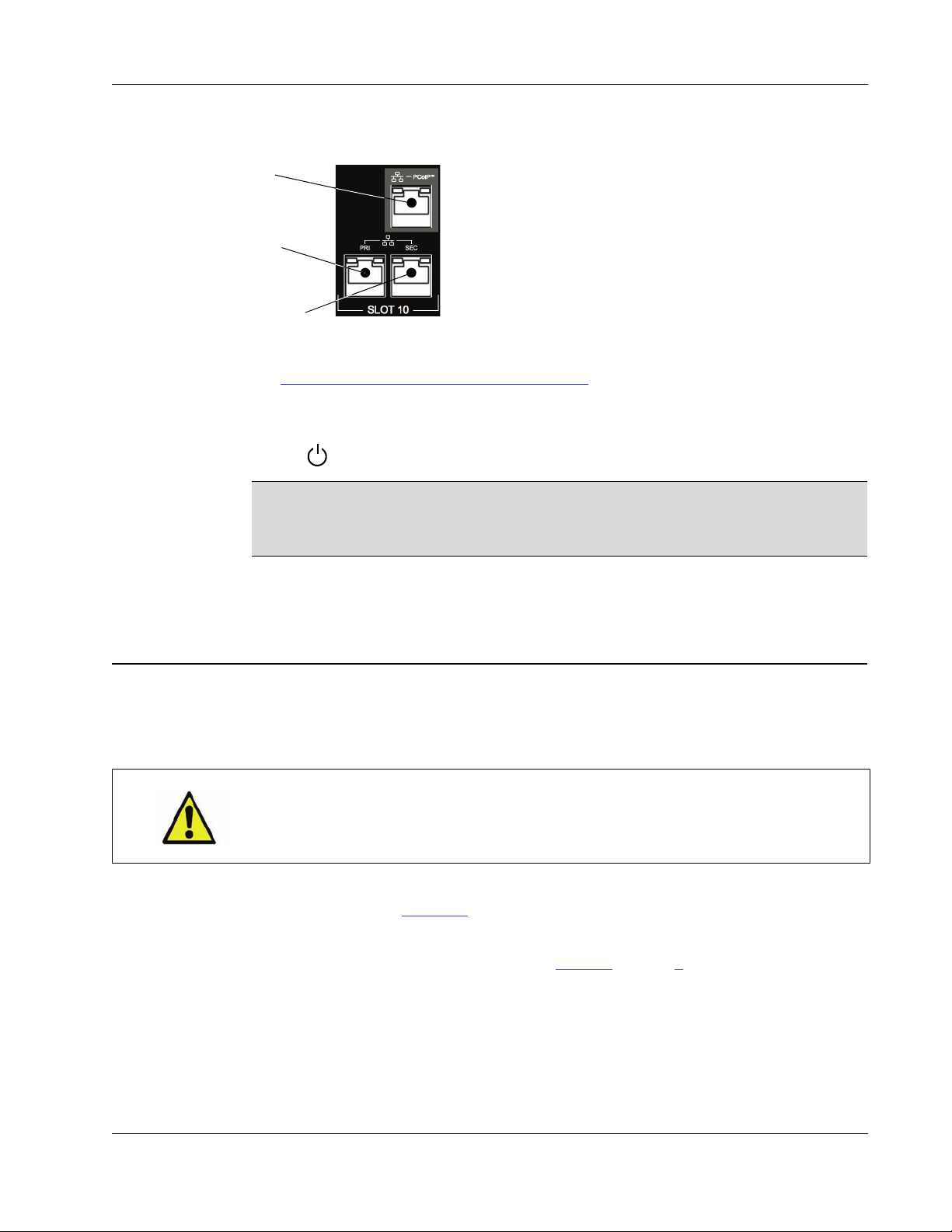
Removing Blade PC from a Chassis
6. Attach one or more Ethernet cables. The picture below shows details of the network
connections for one slot (or blade) on the rear of the expansion backplane.
PCoIP
• PCoIP Port — This port is dedicated to all PCoIP traffic
from the PCoIP host card in an A–Series blade.
Primary
• Pri (Primary Port) — This port is for standard network
traffic.
• Sec (Secondary Port) — This port is for standard
Secondary
See “Chassis Expansion Backplane and Cabling”
network traffic for A6106D blades. A6105D blades do
not support the secondary port.
on page 16 for details about network
connections on the rear of an A3100 chassis and differences between blade models.
7. Power on the blade. On the front of the blade, press the right-most button above the power
symbol .
By default, Blade PCs are configured to power on automatica lly when inserted in
NOTE
a chassis. If the default configuration of a Blade PC BIOS is changed, you must
press the power button to power it on.
8. After you have finished inserting blades, replace the front bezel.
3.5 Removing Blade PC from a Chassis
To remove a blade, perform the following steps.
CAUTION: Some surfaces on the blade may be hot, especially when the blade has
been powered on. Remove and handle the blade with care.
1. Remove the chassis front bezel by pressing the latch on the right side toward the center of
the chassis (shown in Figure 20 above).
2. If the blade is powered on, power down the blade by pressing the power button (the
right-most button) on the front of the blade (Figure 2
3. Using the D-shaped handle on the front panel, pull gently on the blade until it slides out of
the chassis. Be sure to support both ends of the blade when you remove it completely from
the chassis.
Never leave a Blade PC unprotected when not in use. A blade should always be in a chassis or
in a storage box. Dust, dirt, and other debris can damage blades.
on page 4 for location)
ClearCube Technology, Inc. 39
Page 52

Chapter 3. Chassis and Blade PC Installation
40 A–Series Setup and Installation Guide
Page 53
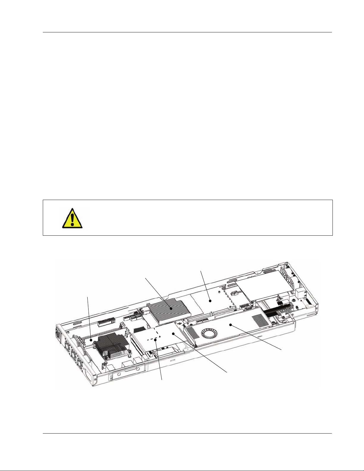
Chapter 4. Upgrading and Maintaining
PCIe x16 Flex Cable
Hard Drive(s)
Memory (DIMM)
Host Card
Video Card (GPU)
PCIe x1 Flex Cable
(on Some Models)
Blade PCs
ClearCube’s A–Series architecture simplifies computer and component upgrades. You can
easily upgrade or replace Blade PC components.
CAUTION: Some surfaces on blades can be hot, especially when the blade
has been powered on. Remove and handle Blade PCs with care.
The following figures show A–Series blades and their major components (depending on
configuration, components in blades can vary).
A–Series Setup and Installation Guide 41
Figure 21. Layout of A6106D
Page 54
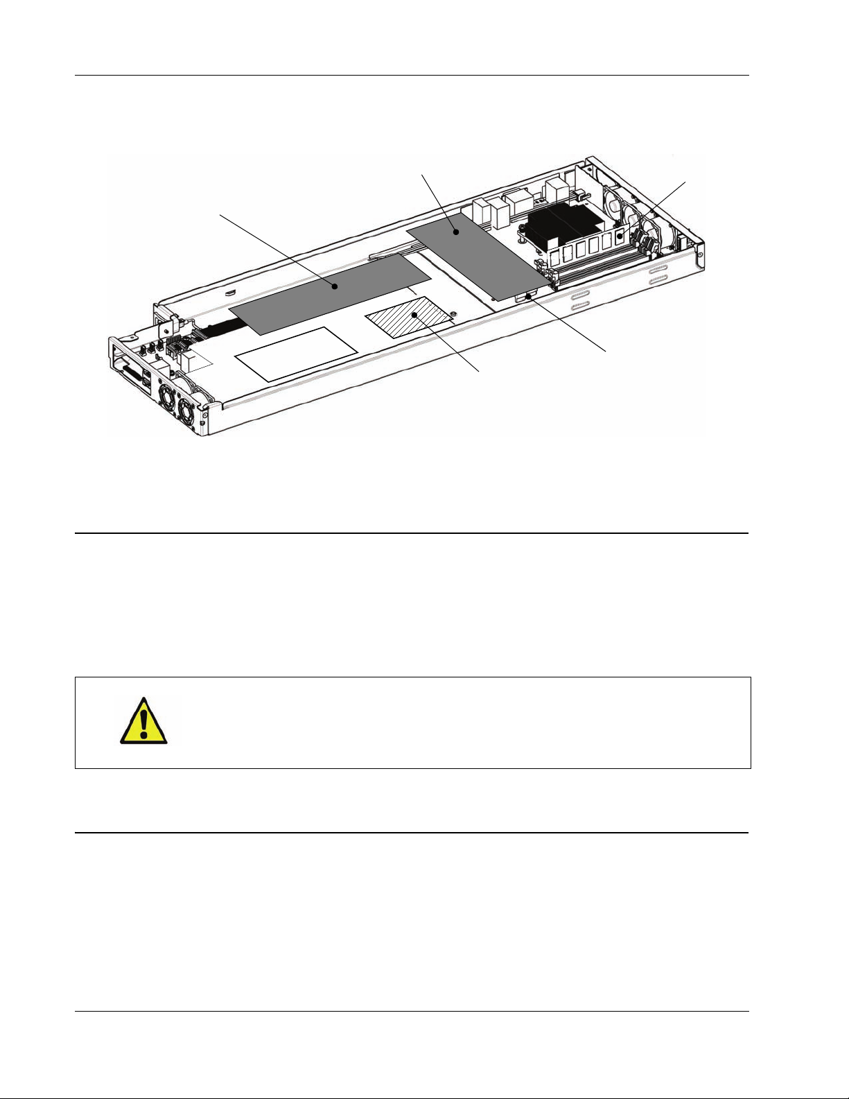
Chapter 4. Upgrading and Maintaining Blade PCs
Memory
Hard Drive
Dual Host Card
Quad Host Card
(On Some Blades)
Hard Drive Cables
Figure 22. Layout of A6105D
4.1 Use Authorized Components
Customers and qualified technicians can upgrade and replace blade components such as
memory and hard drives. To ensure proper operation and to maintain your ClearCube warranty
when performing upgrades, only use commodities that you obtain from ClearCube or from
your Authorized ClearCube Reseller.
CAUTION: All maintenance and upgrades should be performed by a qualified
computer technician. Take proper precautions to avoid electrostatic
discharges by working at a grounded computer equipment repair bench.
Damage caused by improper upgrade procedures will void your warranty.
4.2 Replacing Components: Permitted and Prohibited Units
ClearCube products consist of components, or units, that customers and qualified technicians
can replace. The following list identifies these units.
42 A–Series Setup and Installation Guide
Page 55

Memory
• Customer–Replaceable Units (CRUs)—Items that customers can replace. CRUs include
the following:
– Memory
– Hard drives (solid-state, hybrid, self-encrypting, and hard disk drives)
– Chassis power cords
– Chassis front bezels
– Host cards using PCoIP technology
Components not intended for customer replacement are listed below.
• Field–Replaceable Units (FRUs)—Items that trained service providers and ClearCube
Systems Engineers (SEs) must replace on–site. FRUs include all CRUs and the following:
– Chassis power input units
– Blade power supplies
– Blade fans
– Blade motherboards
Removing any of these FRUs voids your warranty. Contact ClearCube Support Engineers
for information about replacing CRUs or FRUs. See Appendix D. “Warranty”
for information about your warranty.
4.3 Memory
The following sections show features of A–Series blade memory, provide guidelines about
memory configuration, and explain how to install memory.
4.3.1 A6106D Memory Features
A6106D blades use the Intel DQ77MK chipset. The motherboard has four DIMM sockets and
supports the following memory features.
• Two independent memory channels with interleaved mode support
on page 63
• Unbuffered, single-sided or double-sided DIMMs.
NOTE DIMMs with x16 organization are not supported.
ClearCube Technology, Inc. 43
Page 56

Chapter 4. Upgrading and Maintaining Blade PCs
• 32 GB maximum total system memory (with 4 Gb memory technology).
NOTE Minimum recomme nd e d to tal sys te m me m or y: 1 GB
• Non-ECC DIMMs
• Serial Presence Detect
• DDR3 1600 MHz, DDR3 1333 MHz, and DDR3 1066 MHz SDRAM DIMMs
NOTE
DDR3 1600 MHz DIMMs are only supported by 3rd generation Intel Core
processor family processors.
• XMP version 1.3 performance profile support for memory speeds of 1600 MHz or lower
4.3.2 A6105D Memory Features
A6105D blades use the Intel DQ57TM chipset. The motherboard has four DIMM sockets and
supports the following memory features.
• Two independent memory channels with interleaved mode support
• Support for non-ECC, unbuffered, single-sided or double-sided DIMMs with ×8
organization
®
• Support for unbuffered ECC memory when used with an Intel Xeon
series
• 16 GB maximum total system memory (with 2 Gb memory technology).
• Minimum total system memory: 1 GB using 1 Gb ×8 module
• Serial Presence Detect
processor 3400
• DDR3 1333 MHz and DDR3 1066 MHz SDRAM DIMMs
4.3.3 General Guidelines
• For optimum memory compatibility, use only ClearCube-supplied memory.
• Install only identical (same speed, size, and vendor) DIMM pairs for each memory
channel.
44 A–Series Setup and Installation Guide
Page 57
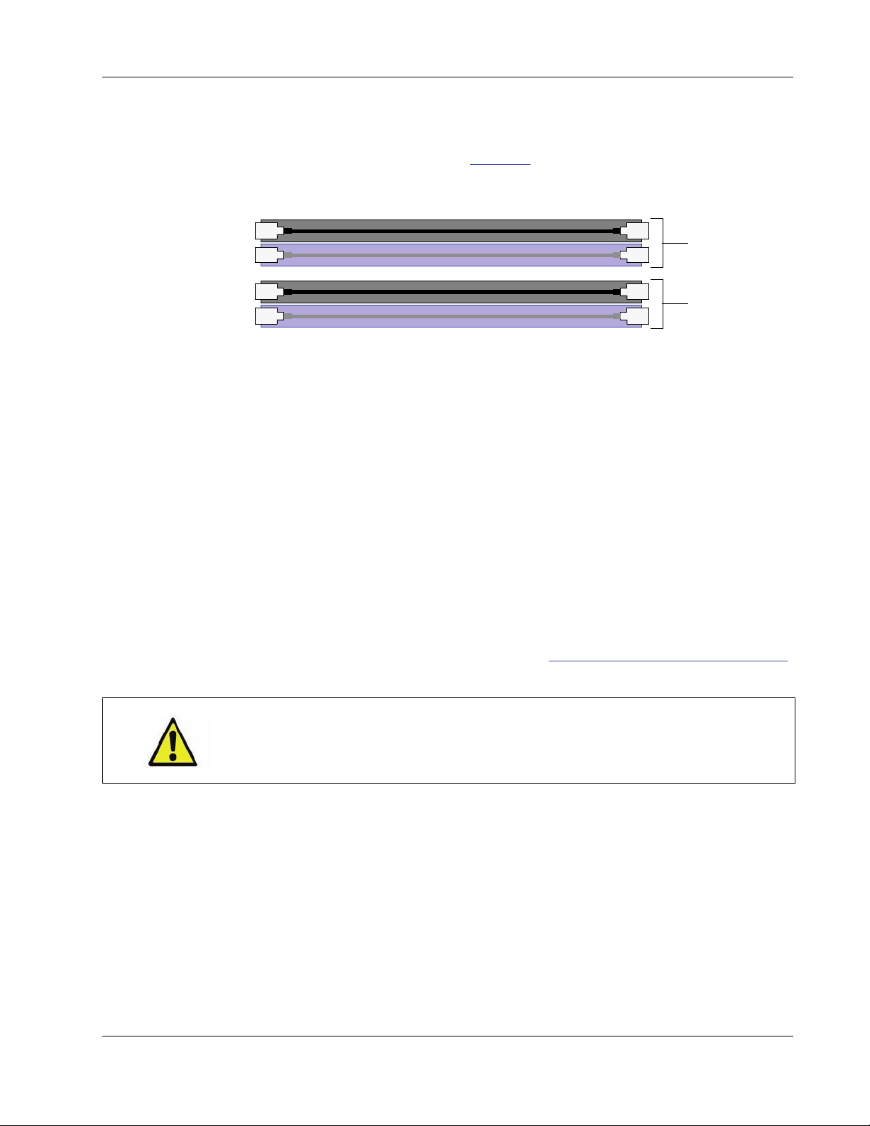
4.3.4 Population Guidelines
DIMM 3
DIMM 1
DIMM 4
DIMM 2
Channel A
Channel B
A–Series blade motherboards have four memory sockets arra nged in two channels with
color-coded memory sockets, as shown in Figure 23
Figure 23. A–Series blade memory sockets and channels
For best performance when populating DIMM sockets
• always start with the blue sockets when installing two DIMMs in your blade, and
below.
Memory
• populate memory sockets in the order shown in the figure above (starting with DIMM 1).
4.3.5 Installing DIMMs
Observe anti-static procedures when you work on blades.
blade, use a #2 Phillips screwdriver.
To replace or upgrade the memory on an A–Series Blade PC, perform the following steps.
1. Remove the blade from the chassis as described in “Removing Blade PC from a Chassis”
on page 39.
CAUTION: Some surfaces on the blade may be hot, especially when the blade
has been powered on. Remove and handle the blade with care.
2. Place the blade on a flat surface and remove the four 6-32 screws on the top cover.
3. Slide the top cover back and remove it from the chassis.
4. Pull the tabs on the sides of the memory socket away from the DIMM socket and remove
the DIMM.
To install DIMMs in an A–Series
5. Insert the new DIMM. Gently press down on the top edge of the DIMM to seat it
completely. If the memory socket latches are not fully closed automatically, press the
memory socket latches onto the sides of the DIMM.
ClearCube Technology, Inc. 45
Page 58

Chapter 4. Upgrading and Maintaining Blade PCs
6. Replace the top cover panel, ensuring that the side walls of the cover are on the outside of
the flanges on the base frame.
7. Replace the four 6-32 screws that retain the top cover.
8. Replace the blade in the ch assis, as described in “Installing Blade PC in a Chassis”
page 38.
9. Replace the chassis front beze l.
10. Power on the blade. Press the right-most button above the power symbol on the front
of the blade.
By default, Blade PCs are configured to power on automa tically when inserted in
NOTE
a chassis. If the default configuration of a Blade PC BIOS is changed, you must
press the power button to power it on.
4.4 Hard Drives
When working with hard drives consider the following:
• Hard drives are sensitive to mechanical shock and are most vulnerable when handled as an
unmounted unit. Handle them gently, especially when setting them down on a surface to
work.
on
• Remove drive cables by pulling on the connector, not the cable. Pull the connector straight
out, not at an angle.
• Imaged drives swapped between different blade models will not function correctly.
• Store unused drives in an anti-static bag in a climate-controlled area.
• When creating an operating system image for A–Series Blade PCs, see “Custom
Operating System Requirements” on page 35
4.4.1 A6106D
A6106D uses a carrier to mount storage drives—such as hard disk drives (HDD), solid state
drives (SSD), self-encrypting drives (SED), and hybrid drives.
The A6106D blade does not support hot-swap replacement of drives. When
NOTE
configuring an A6106D blade outside of a chassis, be sure to power down the blade
and remove the power cable before removing drives or servicing any components.
46 A–Series Setup and Installation Guide
Page 59

Hard Drives
Finger Holes for Carrier Removal
Storage Driver Carrier
Mounting Screws
Drive 0 Drive 1
Storage drives do not require power cables or data cables when mounted in the storage drive
carrier. Power and data connectors are housed inside the blade—insert and fully seat the
carrier and fasten with screws.
The picture below shows the storage drive carrier.
Figure 24. Removing and attaching the storage drive carrier
Drive order: The picture below shows how drive carrier slots correspond to motherboard drive
order.
Figure 25. Hard drive order in the A6106D storage drive carrier
4.4.2 A6105D
To install or replace a hard drive in an A6105D blade, use a #2 Phillips screwdriver to perform
the following steps.
ClearCube Technology, Inc. 47
Page 60

Chapter 4. Upgrading and Maintaining Blade PCs
1. Remove the blade from the chassis, as described in “Removing Blade PC from a Chassis”
on page 39.
CAUTION: Some surfaces on the blade may be hot, especially when the blade
has been powered on. Remove and handle the blade with care.
2. Remove the four 6-32 screws that retain the top cover.
3. Slide the top cover back and remove it from the chassis.
4. Disconnect the SATA and power cables from the hard drive, noting the orientation of the
cables for reassembly.
5. Remove the four screws on the bottom of the blade (shown below) connecting the drive
bracket to the blade frame. Be sure to support the drive(s) to prevent dropping or any
mechanical shock during removal.
Figure 26. Hard drive bracket screw hole location on side of A6105D blade
6. Remove the bracket and hard drives from the blade.
7. Hard drives are connected to the bracket by two M3 screws on each side of the bracket.
Remove the old hard drive (if necessary) and fasten a new hard drive to the bracket with
screws so that the hard drive labels face up.
Figure 27. Install hard drives with labels facing up
48 A–Series Setup and Installation Guide
Page 61

BIOS
8. Place the bracke t and ha rd drive in the blade frame and fasten with screws. Be sure to
reconnect the hard drive power and data cables in the proper orientation.
9. Replace the top cover panel, ensuring that the side walls of the cover are on the outside of
the flanges on the base frame.
10. Replace the four 6-32 screws that retain the top cover.
11. Replace the blade in the chassis, as described in “Installing Blade PC in a Chassis”
12. Replace the chassis front bezel.
13. Power on the blade. Press the right-most button above the power symbol on the front
If necessary, reinstall operating system, drivers, and application software. See “Custom
Operating System Requirements” on page 35 for information about creating custom operating
system images.
4.5 BIOS
The following sections describe
page 38.
of the blade.
By default, Blade PCs are configured to power on automatica lly when inserted in
NOTE
a chassis. If the default configuration of a Blade PC BIOS is changed, you must
press the power button to power it on.
on
• clearing BIOS passwords
• updating blade BIOS, and
• recovering a corrupted BIOS
4.5.1 Clearing BIOS Passwords
You can use the A–Series BIOS setup menu to create supervisor and user passwords that must
be entered to access various options, including accessing the BIOS setup menu. If you need to
reset BIOS passwords, you must move a jumper on the motherboard’s three-pin BIOS
configuration jumper block to configure mode.
The following sections assume that
NOTES
ClearCube Technology, Inc. 49
• BIOS password(s) are se t
• the motherboard is installed in the A–Series blade, and
• the configuration jumper block is set to normal mode.
Page 62

Chapter 4. Upgrading and Maintaining Blade PCs
4.5.1.1 Before You Begin
• These instructions assume that SLP discovery is enabled on the zero client and the blade’s
host card is enabled to accept any peer. See PC-over-IP System User's Guide for more
information.
• Ensure that you can connect a zero client and the A–Series blade to a network switch with
a DHCP server, and that the devices are on the same subnet.
• Find the MAC address of the blade's PCoIP host card listed on a Video Configuration
label on the side of the blade. You will use this MAC address to connect to the blade from
a zero client.
4.5.1.2 Required Items
• A–Series blade and blade power cable
• Monitor and monitor power cable
• USB keyboard
• PCoIP zero client compatible with the host card in the A–Series blade (use a dual zero
client with a dual host card and a quad zero client with a quad host card). Additionally,
both devices must use the same version firmware. (See PC-over-IP System User’s Guide
and PC-over-IP Device Firmwar e Support and Compatibility Guide for information about
firmware and upgrading firmware.)
•USB mouse
• Network switch connected to network with DHCP server
• Two Ethernet cables
• #2 screwdriver
• Optional: needle-nose pliers
4.5.1.3 Setting up Zero Client and Blade PC
CAUTION: Do not move jumpers when the blade is powered on. Always
power off the blade and unplug the power cord from the blade before
moving a jumper. Doing otherwise can damage the motherboard and cause
irreparable damage.
1. Connect a monitor, a mouse, and a power cab le to the zero client.
2. Remove the blade from a chassis and place it on a stable surface, such as a desk or
workbench. Do not connect power to the blade.
3. Use a #2 screwdriver to remove the blade’s cover.
50 A–Series Setup and Installation Guide
Page 63

4. Move the jumper to pins 2 and 3 on the BIOS configuration jumper block.
A6106D
(DQ77MK Motherboard)
A6105D
(DQ57TM Motherboard)
1
2
3
3
2
1
BIOS
The pictures below show the jumper (Figure 28
each A–Series blade (Figure 29
). In the pictures below, host card brackets are omitted for
clarity.
Figure 28. The jumper on the BIOS configur ation block
) and the location of the jumper block on
Figure 29. BIOS jumper block location and jumper pin numbers on A6106D and on A6105D motherboards
• For A6105D blades, move the jumper to pins 2 and 3 (Figure 29) and continue to step 5.
• For A6106D blades, the jumper block is located beneath the PCoIP host card bracket. For
blades with:
– Dual-monitor host cards: access the jumper through the opening in the PCoIP host
card bracket. Use needle-nose pliers to move the jumper to pins 2 and 3 (see the figure
above). Continue to step 5
.
– Quad-monitor host cards: remove the host card and bracket to access the jumper.
a. Press the release lever on the PCIe ×16 slot to release the silver PCIe ×16 flex
cable (only release the end nearest the DIMM slots). Gently lift up the cable,
being sure not to crease or bend it.
b. If the host card is a Tera 1 card (roughly 11.75 inches long with a silver heat sink
and fan), continue to step c
ClearCube Technology, Inc. 51
below. If it is a Tera 2 card (roughly 6.5 inches long
Page 64

Chapter 4. Upgrading and Maintaining Blade PCs
with a black heat sink), remove the end of the silver PCIe ×1 flex cable that is
connected to the host card. Remove both screws and gently remove the cable,
being sure not to crease or bend it.
c. Remove Ethernet cable(s), being sure to note their arrangement for correct
reassembly. If present, remove video cables (for example, Mini DisplayPort) from
the host card.
d. Remove screws from the host card and carefully remove the card from the bracket
(you can safely leave the power cable connected).
e. Move the jumper to configuration mode (pins 2 and 3). Use needle-nose pliers to
ease access. See the figure above for jumper placement.
f. Replace the host card bracket and host card, including all cables, by reversing
these steps.
5. Replace the blade cover and fasten with screws.
6. Connect a USB keyboard to a USB connector located on the top edge of the blade (you
might need to move a safety cover that covers the ports). (This is referred to as a local
keyboard in these instructions, as distinguished from a keyboard connected to a zero client.)
7. Use Ethernet cables to connect the zero client and the blade to a network switch. Use the
blade’s dedicated PCoIP port - the right-most port on the rear of the blade (see picture
below).
Figure 30. A–Series blade dedicated PCoIP port
8. Power on the zero client (do not power on the blade).
Result: After several moments the zero client's On-Screen Display (OSD) is displayed.
4.5.1.4 Connecting Zero Client and Blade PC
1. Ensure that a local keyboard is connected to a USB port on the top edge of the blade.
2. Conn ect power to the rear of the A–Series blade and press the power button on the front
of the blade (the right-most button) to power on the blade.
52 A–Series Setup and Installation Guide
Page 65

BIOS
3. Watch the lights on the keyboard - when the lights blink or illuminate, wait for about 10
seconds. From the OSD (the monitor connected to the zero client), click Connect.
Result: a progress message is displayed. After several moments the OSD displays a list of
available host cards.
4. Use the host card's MAC address to identify it in the list (you might need to scroll down
to find the host card). If you do not see the host card, power off the zero client and power
it on again, then click Connect. Select the host card and click OK.
Result: the BIOS Maintenance menu is displayed.
4.5.1.5 Clearing Passwords
1. From the BIOS Maintenance menu, select Clear BIOS Passwords and press ENTER on
the local keyboard.
Result: Feedback depends on the blade model:
– A6106D: A dialog box is displayed asking you to confirm clearing the password(s).
Press Y to clear the password(s).
– A6105D: The screen blinks, and no other feedback or message is displayed.
2. Verify that passwords are cle ared. Press arrow keys on the local keyboard to scroll to the
Security menu. From the top portion of the screen, ensure that all passwords display
Not Installed.
3. From the loc al keyboard, press F10 to save the BIOS changes. Select Yes (depending on
the BIOS, you might need to press ENTER to continue).
Result: A message is displayed about powering off the blade and moving the jumper.
4. Power off the blade by pressing the power button on the front of the blade.
5. Remove the power cable from the rear of the blade.
6. Use a screwdriver to remove the blade cover.
7. Return the BIOS configuration jumper to pins 1 and 2 (see Figure 29
on page 51 for the
jumper location).
8. Replace the blade cover and fasten with screws.
BIOS passwords are now cleared. You can now deploy the blade or create new passwords by
viewing the BIOS Security menu.
4.5.2 Updating (Flashing) BIOS
A–Series blades use a customize d BIOS. Use only ClearCube BIOS updates on A–Series
blades. To download BIOS updates from the ClearCube Support site, perform the following
steps.
ClearCube Technology, Inc. 53
Page 66

Chapter 4. Upgrading and Maintaining Blade PCs
1. Go to ClearCube Support at www.clearcube.com/support/.
2. Select the appropriate A–Series blade in the Blade PCs drop-down list box.
3. Click the BIOS link to display a list of BIOS downloads.
4. To download a BIOS, click the appropriate link and save the file to your computer. The
.ZIP file contains a readme file with instructions about how to update the BIOS.
4.5.3 Recovering BIOS
If the BIOS on your A–Series blade becomes corrupted or you need to recover your BIOS for
any other reason, follow the instructions in the documentation (Desktop Boards Instructions
for Recovery BIOS update) on the Intel support site (www.intel.com
).
Motherboard model numbers are shown in Appendix A. “Specifications”
on page 55, and are
also shown on the motherboard. From the Intel Support site, search for the BIOS for your
blade’s motherboard.
54 A–Series Setup and Installation Guide
Page 67

Appendix A. Specifications
Table 3. A6106D Blade PC Specifications
Component Description
Depending on configuration:
• Intel Xeon Processor E3-1275 v2
Processor
Chipset Intel Q77 Express Chipset
Memory
Video
LAN Support
Intel® vPro™
Technology
support
• Intel Core™ i7
• Intel Core i5
• Intel Pentium
• Dual-Channel
• DDR3 1600 and 1333 MHz
• Four DIMM sockets, unbuffered, non-ECC
• Supports up to 32 GB
Supports dual- and quad-head digital host cards with PCoIP
technology
Two Gigabit (10/100/1000 Mb/s) LAN su bsy ste m s usin g
Intel 82579LM and Intel 82574L Gigabit Ethernet Controllers
Provides remote management support
®
Processor G2120
• Windows 7
Operating System
Support
A–Series Setup and Installation Guide 55
• Windows XP
•Linux
®
–ready
Page 68

Table 3. (Continued) A6106D Blade PC Specifications
BIOS Intel BIOS (resident in SPI flash device)
• Size: 10.03 inch (H) x 29.22 inches (L) x 1.63 inches (W)
Dimensions
• Weight: 14.5 pounds
Stationary office, 0–35° C
Environment
Relative humidity (non-condensing):
• Operating: 15% - 80%
• Non-operating: 5% - 95%
Table 4. A6105D Blade PC Specifications
Component Description
• Intel Core i7
Processor
• Intel Core i5
Chipset Intel Q57 Express Chipset
• Dual-Channel
• DDR3 1333 and 1066 MHz
Memory
• Four DIMM sockets, unbuffered, non-ECC
• Supports up to 16 GB
Video
LAN Support
Supports ClearCube V5220 and V5240 dual- and quad-head digital
host cards with PCoIP technology
Gigabit (10/100/1000 Mbits/sec) LAN subsystem using Intel
82578DM Gigabit Ethernet Controller
Intel® vPro™
Technology
Provides remote management support
support
• Windows XP, Server 2003, Server 2008, Windows Vista, and
Operating System
Support
Windows 7
• Linux–ready
BIOS Intel BIOS (resident in SPI flash device)
56 A–Series Setup and Installation Guide
Page 69
Dimensions
Table 4. (Continued) A6105D Blade PC Specifications
• Size: 10.03 inch (H) x 29.22 inches (L) x 1.63 inches (W)
• Weight: 14.5 pounds
Stationary office, 0–35° C
Environment
Relative humidity (non-condensing):
• Operating: 15% - 80%
• Non-operating: 5% - 95%
Table 5. A3100 Chassis Specifications
Feature Description
• 6U form factor, 10-slot chassis
Connections
• Fit 7 chassis (70 Blade PCs) in a single 42U rack or cabinet
• Four AC power connectors: one main and one redundant A/C line
connections for every 5 slots
• 6U (10.5 inches high, standard 19-inch rack width)
Dimensions
• 17.0-inch (w) x 10.5-inch (h) x 29.75-inch (d)
• 100–240 VAC, 50/60 Hz
Power Input
• Power supplied to each individual blade slot
• 12 Amps current required per power input (at 100 VAC)
(maximum)
AC Input Fuse T15A, 250V (5x20 mm slow-acting 15 amp fuse)
Weight
40 pounds empty, 192.5 pounds with 10 blades and expansion
backplane
Environmental Rack mounted, 0–35º Celsius (C)
ClearCube Technology, Inc. 57
Page 70

58 A–Series Setup and Installation Guide
Page 71

Appendix B. Regulatory Compliance
The products described in this document meet the following:
• Electromagnetic Compatibility (EMC)
• Various safety compliance standards
• CE compliance
• Various environmental standards, including RoHS and REACH
See http://www.clearcube.com/support/
ClearCube Technology, Inc. products.
for regulatory and environmental certifications for
A–Series Setup and Installation Guide 59
Page 72

60 A–Series Setup and Installation Guide
Page 73

Appendix C. Support
C.1 Contact Information
If any problems arise with your ClearCube hardware or software, check the support Web site
for any relevant technical bulletins and updates for your product(s) before calling your
authorized reseller or ClearCube Support. If your system is serviced by a local ClearCube
service partner (such as an authorized reseller), see the contact information provided by the
service partner or see the ClearCube Web site for partner contact information. Use any of the
methods shown below to contact ClearCube Support.
support@clearcube.com
clearcube.com/support/ ClearCube Support Web site
www.
www.clearcube.com/support/
+1-866-652-3400 ClearCube Support from outside US
+1-512-652-3400 ClearCube Support in the US
ClearCube Support email address
Service request and RMA form
C.2 Return Merchandise Authorization (RMA)
ClearCube’s policy for products under warranty is to ship replacement parts to the customer
within 24-48 hours after the replacement has been approved by the ClearCube Support.
If you are instructed to return any hardware, you must obtain a Return Merchandise
Authorization (RMA) number from ClearCube and clearly mark the RMA number on the
outside of all shipments to ensure proper and prompt handling. Do not return any equipment
without the appropriate ClearCube packaging materials. If you no longer have ClearCube
shipping containers, contact Support for replacements.
A–Series Setup and Installation Guide 61
Page 74

If an issue arises that requires a warranty replacement part:
• Call Support (+1-512-652-3400 or +1-866-652-3400)
• e-mail s
• use the RMA form on the Support Web site (www.clearcube.com/support/
product issue.
Provide the following information for all product RMAs:
• Name and address
• Product serial number(s)
• Product configuration information
• A brief description of the issue.
Once submitted, Support opens a ticket and provides a case number to the customer. Support
then gathers information about the issue and performs troubleshooting processes to determine
if a replacement part is required.
If the product is covered under warranty, Support ships a replacement to the customer.
If the product is not under warranty, Support advises the cu sto mer abou t replacement options,
or provides information about the manufacturer’s warranty for non-ClearCube-branded
products.
upport@clearcube.com, or
) to report the
Customers who choose to purchase replacement products should contact their Account
Executive to confirm and coordinate the replacement purchase.
C.3 Power Cord Replacement
ClearCube A–Series equipment is designed with a three-conductor IEC 60320 appliance inlet
that—with the proper power cord—connects a building’s external protective earthing
conductor to all accessible metal parts of the enclosure. To minimize shock hazard, make sure
your electrical power outlet has an appropriate earth safety ground that is connected each time
you power on equipment.
Only use the AC power cords packaged and supplied with your product or power cords and
adapters obtained from ClearCube. See “Contact Information”
about contacting ClearCube Support for replacement power cords and adapters.
on page 61 for information
62 A–Series Setup and Installation Guide
Page 75

Appendix D. Warranty
The ClearCube warranty is available on the Support site:
http://www.clearcube.com/support/
From the Support site, click the ClearCube Warranty Ove rv iew link to view the ClearCube
warranty.
See “Contact Information”
Support.
on page 61 for information about how to contact ClearCube
A–Series Setup and Installation Guide 63
Page 76

64 A–Series Setup and Installation Guide
Page 77

Index
NOTE
Italic numbers refer to figures, diagrams, and illustrations.
Symbols
10
Numerics
6105. see A6105D
6106. see A6106D
A
A3100 chassis 8, 9, 16–20
A-B (power receptacles) 30
brackets 24–27
cabling 16
C-D (power receptacles) 30
chassis accessory kit 22, 23
chassis rapid-mount kit 23
container contents 22
cooling and airflow 14–15
definition 1
description 7
expansion backplane installation 28–29
ground strap kit 22, 24, 25
inspecting shipment 11
installation of 21–31
installing Blade PC in 38
PCoIP port 16, 17
power 9, 15
A-B (power receptacles) 30
AC tray 30
C-D (power receptacles) 30
power cords 22, 23
primary port 16, 17
secondary port 16, 17
specifications 57
storage of 12
unpacking 11–12, 22
UPS and PDU 30
weight 14, 57
A6105D
see also Blade PC
BIOS jumper
component and feature overview 6
component layout 42
hard drive bracket
operating system, supported 56
specifications 6, 56
A6106D
see also Blade PC
BIOS jumper
component and feature overview 5
component layout 41
operating system, supported
specifications 5, 55
storage drive carrier 4, 47
AC tray, A3100 chassis 9
A-B power receptacle 9
C-D power receptacle 9
allocation of devices. see Sentral
AMBnnnnn (serial number)
architecture 2
example deployments
of A-Series devices 1
auto power-on, Blade PC 39
AVCnnnnn (serial number) 5
51
48
51
55
5
18
B
backplane. see expansion backplane
BIOS
jumper
modify, flash, and recover 49–54
viewing 31–34
Blade PC 3
see also A6105D; A6106D
auto power-on
BIOS passwords 49–53
51
39
A–Series Setup and Installation Guide 65
Page 78

Index
cable requirements 17
components 3
authorized 42
cable
PCIe × 1 flex
PCIe × 16 flex
GPU (video card)
hard drive
host card
memory
video card (GPU) 41
configuration label
configure out of chassis 31–34
connectors, top edge 4
cooling and airflow 14–15
definition 1
drive activity indicator 4
Ethernet connector 4
handle 4
hot surfaces 39
I/O access slot 4
inspecting shipment 11
installation 21–31
installing in A3100 chassis 38
installing operating system 34–38
labels 4, 5
LCD 4
LCD bezel 4
overview 2–4
power 30–31
power connector 4
power indicator 4
power requirements 15
removing from chassis 39
reset button 4
specifications 5, 6
A6105D 56
A6106D 55
storage drive carrier (A6106D) 4
storage of 12
unpacking 11–12
Blades 1-5 (power and chassis label) 30
Blades 6-10 (power and chassis label) 30
boot from network 37
boot screens 31–34
41, 42
41, 42
41, 42, 43–46
41
41
41
5
bracket
chassis, installing
hard drive
A6105D
A6106D 47
broker. see Sentral
24–27
48
C
cabinet. see rack
cable
see also power: cords
PCIe × 1 flex cable, A6106D
PCIe × 16 flex cable, A6106D
California Proposition 65
caution
high leakage current
hot surfaces, Blade PC 39
hot-swap prohibition, A6106D 46
two-post rack prohibition 23
caution notice x
channels, memory 45, 45
chassis accessory kit
chassis rapid-mount kit 23, 25–27
chassis. see A3100 chassis
circuit considerations
client 2
see also thin client; zero client
clinical use of products
Cloud Desktop 3
see also zero client
definition
COA label 5
codes, electrical x
compatibility, electromagnetic 59
compliance, safety 59
computer. see Blade PC
configuration label, Blade PC
connection broker. see Sentral
connectors
Ethernet, Blade PC (rear)
various, Blade PC (top) 4
cooling and airflow 14–15
1
vii
27
22, 23
15
viii
5
4
D
damage to shipment 11
41
41
66 A–Series Setup and Installation Guide
Page 79

Index
dedicated PCoIP network 19
deployment
examples
overview 2
desktop. see Blade PC
device drivers. see drivers, Blade PC
DIMM. see memory, Blade PC
display
see also monitor support
LCD
drive activity indicator 4
drivers, Blade PC 36
18–20
4
E
electromagnetic compatibility (EMC) 59
EMC. see electromagnetic compatibility
emissions
Equipment Protection Class II ix
Ethernet
expansion backplane 7–9, 9, 22
59
see also I/O access slot, Blade PC
and PCoIP
cable requirements 17
cable support 18
connector
port when Blade PC out of chassis 33
attaching to A3100 chassis 22
definition 7
installation 28–29
ports
removal 29
16
Blade PC
expansion backplane 16, 39
PCoIP port
primary port 16
secondary port 16
4
16
F
failover power, chassis 30–31
FCC warning vii
firmware revision label 5
fuse symbol ix
G
GPU 10
ground bond terminal symbol ix
ground strap kit 22, 24, 25
guidelines, safety x
H
handle, Blade PC 4
hard disk drive. see hard drive
hard drive
HDD. see hard drive
heads. see monitor support
high leakage current caution
host card
4, 46–49
A6105D 47–49
A6106D 46–47
firmware revision label
MAC address 5
27
5
I
I/O access slot, Blade PC 4
identification labels 5
image. see operating system
immunity
indicators
installation
59
drive activity
LCD bezel 4
power, blade 4
see also upgrading
A3100 chassis
Blade PC 21–31
Blade PC in chassis 38
chassis accessory kit 23
chassis rapid-mount kit 23
electrical codes x
expansion backplane 28–29
memory 45–46
tools for 21
4
21–31
J
jumper, BIOS 51
L
labels 4
blade MAC 5
Blade PC 5
ClearCube Technology, Inc. 67
Page 80

Index
blade serial number 5
host card firmware revision 5
Intel inside 5
operating system COA 5
regulatory 5
system configuration 5
video configuration 5
LCD bezel, Blade PC 4
lead. see California Proposition 65
LED. see indicators
lockout, mass storage
1
M
MAC address 4, 5
management software. see Sentral
manual, refer to (symbol)
mass storage lockout (MSL) 1
medical use of products viii
memory, Blade PC 43–46
A6105D 6, 44
A6106D 6, 43–44
channels 45
monitor support
mounting bracket, rack 13
mounting. see installation
MSL. see mass storage lockout
multi-head. see monitor support
10
ix
N
network
see also Ethernet
37
boot
cable requirements by blade model 17
chassis cabling 16–18
examples 18–20
overview 2
O
OOBE 31–34
operating system (OS)
COA label
creating custom 35–37
installing 34–38
OOBE, viewing 31–34
supported
5
A6105D
A6106D 55
OS. see operating system
56
P
passwords, clearing BIOS 49–53
PC. see Blade PC
PCIe × 1 flex cable, A6106D
PCIe × 16 flex cable, A6106D
PCoIP
see also I/O access slot on Blade PC; PC-over-IP
System User’s Guide
cabling
connecting to blade out of chassis 33
dedicated port on expansion backplane 17, 39
PDU 30
portal. see zero client
ports
see also Ethernet; USB
I/O access slot
on expansion backplane 8–9, 16–17
overview 4
power
A3100 chassis UPS and PDU
AC tray 9
Blade PC, auto-power on 39
Blades 1-5 (chassis label) 30
Blades 6-10 (chassis label) 30
button, on Blade PC 4
chassis AC tray 9
circuit considerations 15
connector, on Blade PC 4
cords
failover, A3100 30
ground strap kit 24, 25
high leakage current caution 27
indicator on Blade PC 4
requirements
reset button 4
symbol ix
power distribution unit. see PDU
17
4
A3100 chassis
replacing 62
A3100 chassis
Blade PC 15
41
41
30
22, 23, 25
15
68 A–Series Setup and Installation Guide
Page 81

Index
pre-OS video 31–34
primary port (expansion backplane) 16, 17
protective earth terminal symbol ix
PXE boot 31–34
R
rack
see also chassis
installing
mounting bracket 13
requirements 13–14, 15
two-post rack prohibition 23
weight 14
rails, mounting. see chassis rapid-mount kit; chassis
REACH
regulatory
California Proposition 65
clinical use viii
electromagnetic compatibility (EMC) 59
emissions 59
FCC warning vii
immunity 59
medical use viii
REACH 59
RoHS 59
safety compliance 59
WEEE information vii
reset button 4
resolution 10
RoHS 59
23
accessory kit
59
vii
server. see Blade PC
shared network
shock hazard, symbol ix
software, management. see Sentral
specifications
A3100 chassis
A6105D 6, 56
A6106D 5, 55
expansion backplane 7
SSD. see hard drive
startup screens, viewing
stickers. see labels
storage drive carrier
see also hard drive
storing devices (Blade PCs and chassis)
Support, contacting 61
symbols
equipment protection, class II
fuse ix
ground bond terminal ix
manual, refer to ix
power ix
protective earth terminal ix
shock hazard ix
system configuration label 5
20
7, 57
31–34
4
ix
T
Tech Support. see Support, contacting
Thermal. see cooling and airflow
thin client
tools for installation 21
1
12
S
safety compliance 59
safety guidelines x
secondary port (expansion backplane) 16, 17
security (mass storage lockout) 1
SED. see hard drive
Sentral
serial number
ClearCube Technology, Inc. 69
1
see also PCoIP; Sentral Administrator’s Guide
AMBnnnnn
AVCnnnnn
label
4, 5
PC Blade 5
5
5
U
uninterruptible power supply (UPS) 30
upgrading 41–54
BIOS 49–54
hard drive
A6105D
A6106D 46–47
memory 43–46
UPS 30
USB
see also I/O access slot on Blade PC
mass storage lockout
peripherals, connecting 3
47–49
1
Page 82

Index
user types 2
V
ventilation. see cooling and airflow
video
BIOS, viewing
configuration label 5
pre-OS 31–34
virtualization 2
VMware View 2
31–34
W
warning notice x
warranty information 63
WEEE information vii
weight
A3100 chassis
rack 14
14
Z
zero client 3
connect to blade out of chassis 31–34
definition 1
monitor support 10
view pre-OS video 31–34
70 A–Series Setup and Installation Guide
Page 83

Page 84

Rev 1.6.05.10.2013
P/N G020080
clearcube.com
 Loading...