

Page 1
Op er ating In struc tions
R
Intercom Systems
WBS-680, WTR-680, WTR-682
Pro fes sional
Wire less
In ter com Sys tem
Page 2

Thank you for choos ing Clear-Com
Clear-Com In ter com Systems would like to take this op por tu nity to thank you for choos ing the Clear-Com
WBS-680 Pro fes sional Wire less In ter com Sys tem. Many of the fea tures in this prod uct are the re sult of years of
de vel op ment work with many of the fea tures de vel oped from cus tomer feed back. We hope that your ex pe ri ence
with this prod uct is a pleas ant one and hope to pro vide you with a con tin u ing line of Clear-Com prod ucts well
into the fu ture. In or der to get the most out of your new wire less in ter com sys tem, please take a few mo ments to
look through this book let be fore us ing the prod uct for the first time.
Clear-Com In ter com Systems
Page 3

Ta ble of Con tents
In tro duc tion ..........................................................................1 -1
Gen eral De scrip tion ..........................................................................1 -1
Sys tem Fea tures .............................................................................1-1
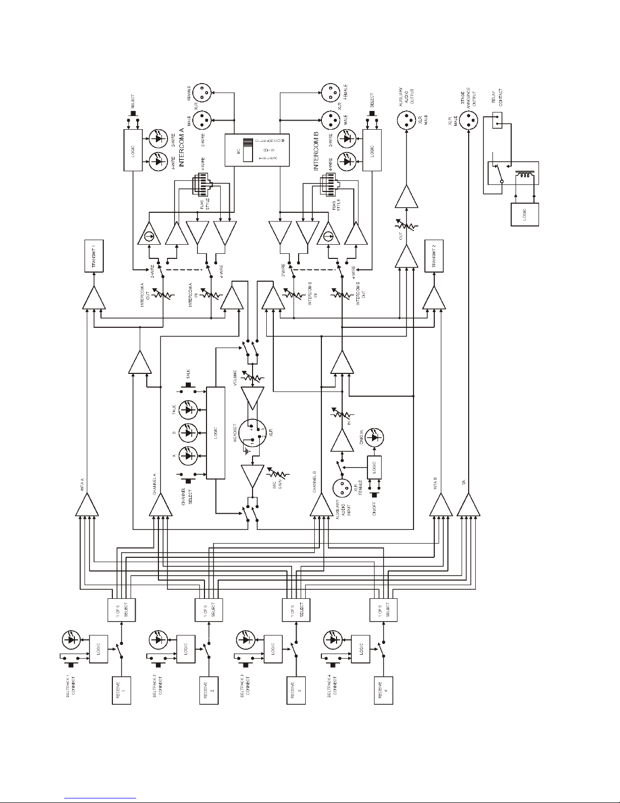
WBS-680 Block Di a gram .....................................................................1-2
WBS-680 Base Sta tion ..................................................................2-1
Con trols and Con nec tions - Front Panel ..........................................................2-1
Con trols and Con nec tions - Rear Panel ...........................................................2-2
WBS-680 Spec i fi ca tions ......................................................................2-3
WTR-680 Beltpack.....................................................................3-1
Con trols and Con nec tions - Top Panel............................................................3-1
Con trols and Con nec tions - Rear Panel ...........................................................3-2
WTR-680 Spec i fi ca tions ......................................................................3-3
WTR-682 Beltpack ....................................................................4-1
Con trols and Con nec tions - Top Panel............................................................4-1
Con trols and Con nec tions - Rear Panel ...........................................................4-2
WTR-682 Spec i fi ca tions ......................................................................4-3
Ini tial Equip ment Set-Up ...............................................................5-1
Un packing .................................................................................5-1
An tenna Con nec tions.........................................................................5-2
An tenna Po lar iza tion .........................................................................5-2
Dis tance Be tween An tennas ...................................................................5-2
An tenna Place ment ..........................................................................5-2
Im proving Re cep tion/In creasing Range ..........................................................5-4
Base Sta tion Set-Up .........................................................................5-5
Lo ca tion ...............................................................................5-5
Power Con nec tion........................................................................5-5
Trans mit Switches........................................................................5-5
In ter nal Trans mit Switches .................................................................5-6
In ter com Switch .........................................................................5-6
In ter com In ter face........................................................................5-6
Dual Lis ten Func tion al ity ..................................................................5-7
Aux il iary In put/Out put ....................................................................5-8
In ter nal Aux il iary In put Routing Switch ......................................................5-8
Stage An nounce /Re lay Con tacts ............................................................5-9
Base Sta tion Link .......................................................................5-10
Beltpack Set-Up ...........................................................................5-11
Bat tery In stal la tion ......................................................................5-11
An tenna Con nec tion .....................................................................5-12
Trans mit Mode .........................................................................5-12
Head set Con nec tion .....................................................................5-12
Pre-Walk-Thru Check list ...............................................................6-1
Sys tem Op er a tion ......................................................................7-1
Fre quency Plan Over view .....................................................................7-1
Fac tory-Defined Group .......................................................................7-1
User-Programmable Groups ...................................................................7-1
Sys tem Quick Start ..........................................................................7-1
Base Sta tion Op er a tion ......................................................................7-2
Power .................................................................................7-2
Lo cal Head set ...........................................................................7-2
Por ta ble Sta tion Con nect ..................................................................7-2
In ter com A and B ........................................................................7-2
Aux il iary...............................................................................7-2
Dis play Con trast .........................................................................7-3
WBS-680 Menu Struc ture ................................................................7-4
Main Screen Flowchart .................................................................7-4
Power-Up Screen ......................................................................7-5
Op er ating Screen ......................................................................7-5
Beltpack Ac tiv ity Code Def i ni tions ........................................................7-5
Group/Chan nel Se lect ..................................................................7-6
Group/Fre quency Se lect.................................................................7-7
Fre quency Edit .......................................................................7-8
Scan ................................................................................7-9
Spe cial Key Se quences ................................................................7-10
Lock out .........................................................................7-10
Copy ...........................................................................7-10
1st Use De fault ...................................................................7-10
Fac tory De fault ...................................................................7-10
-i-
Page 4

Ta ble of Con tents (con tin ued)
WTR-680 Beltpack Op er a tion ...............................................................7-11
Power/Lo cal Head set Vol ume..............................................................7-11
Bat tery Check ..........................................................................7-11
Talk But ton ............................................................................7-11
Mi cro phone Gain .......................................................................7-11
Chan nel Se lect But ton ...................................................................7-11
Stage An nounce (SA) ....................................................................7-11
Wire less Talk Around (WTA)..............................................................7-11
WTR-680 Beltpack Menu Struc ture .......................................................7-12
Power-Up Screens ....................................................................7-13
Group/Chan nel Screen .................................................................7-14
Trans mit Screen ......................................................................7-15
Re ceive 1 Screen .....................................................................7-16
Re ceive 2 Screen .....................................................................7-17
ClearScan™ .........................................................................7-18
Fea ture En able/Dis able Menus ..........................................................7-19
Stage An nounce En able/Dis able .........................................................7-19
Wire less Talk Around En able/Dis able .....................................................7-19
Au dio Chan nel A or B En able/Dis able ....................................................7-20
Talk But ton Latch on/Latch off ..........................................................7-20
Spe cial Key Se quences ................................................................7-21
Lock out .........................................................................7-21
1st Use De fault ...................................................................7-21
Fac tory De fault ...................................................................7-21
WTR-682 Beltpack Menu Struc ture .......................................................7-22
Power-Up Screens ....................................................................7-23
Group/Chan nel Screen .................................................................7-24
Trans mit Screen ......................................................................7-25
Re ceive 1 Screen .....................................................................7-26
Re ceive 2 Screen .....................................................................7-27
Au dio Out put ........................................................................7-28
Scan ...............................................................................7-29
Fea ture En able/Dis able Menus ..........................................................7-30
Stage An nounce En able/Dis able .........................................................7-30
Wire less Talk Around .................................................................7-31
Au dio Chan nel A Op tions ..............................................................7-32
Au dio Chan nel B Op tions ..............................................................7-33
Spe cial Key Se quences ................................................................7-34
Lock out .........................................................................7-34
1st Use De fault ...................................................................7-34
Fac tory De fault ...................................................................7-34
Sys tem Walk-Thru.....................................................................8-1
Trou ble Shoot ing ......................................................................9-1
Tech Tips ............................................................................10-1
Fre quency In ter ac tion .......................................................................10-1
Mi cro phone Gain Ad just ment .................................................................10-1
Bat tery In for ma tion ...................................................................11-1
In ter com Sys tem Spec i fi ca tions .........................................................12-1
Ac ces sories and Re place ment Parts ......................................................13-1
Cus tomer Ser vice In for ma tion ..........................................................14-1
FCC In for ma tion .....................................................................15-1
Limited Warranty ....................................................................16-1
-ii-
Page 5

Section
1
In tro duc tion
Gen eral De scrip tion
The Clear-Com WBS-680 UHF Syn the sized Wire less in ter --
com sys tems of fer the ul ti mate in re li able, high-performance,
high-fidelity full-duplex com mu ni ca tions.
The WBS-680 sys tem in cludes the WBS-680 fre quency ag ile
base sta tion, work ing with up to four WTR-680 or WTR-682
fre quency ag ile beltpacks. The WBS-680 base sta tion pro --
vides full-duplex com mu ni ca tions with the beltpacks.
The BTR sys tem in cor po rates two au dio chan nel op er a tion,
per mit ting the beltpack op er a tor to choose be tween two sep a --
rate au dio chan nels of com mu ni ca tions, with the base sta tion
track ing the beltpack se lec tion. This al lows the user the flex i --
bil ity to cre ate a party-line and a pri vate line within the same
beltpack.
The WBS-680 sys tem is per fectly suited for stand-alone op er --
a tion and also can in ter face with Clear-Com, Audiocom®
(Telex), RTS® TW, as well as Clear-Com MA TRIX PLUS®
sys tems and other 4-wire com mu ni ca tions sys tems. In ad di tion
to the ex ter nal in ter com sys tems in ter faces listed above, the
sys tem pro vides con nec tions for aux il iary bal anced au dio in --
put and out put, as well as wire less talk-around (WTA) and
stage an nounce (SA) fea tures.
The Clear-Com WBS se ries has been de signed for re li able, ef --
fi cient op er a tion. Op er ating in the 518 to 740 MHz range, the
units op er ate re li ably at line-of-sight dis tances of 1,000 feet.
With op tional ex ter nal antenna sys tems, the ef fec tive op er at --
ing range can be ex tended. The high-efficiency beltpacks pro --
vide up to 12 hours of un in ter rupted op er a tion us ing stan dard
al ka line bat ter ies.
Sys tem Fea tures
Fre quency-agile base sta tion and beltpacks. No ex ter nal
•
com puter/de vice re quired to se lect fre quen cies.
Backlit base-station LCD al lows the user to eas ily mon i -
•
tor the beltpack’s sta tus as well as change base-station fre quen cies.
ClearScan™ func tion on base sta tion and beltpack to au -
•
to mat i cally find the best chan nels on which to op er ate.
Full-duplex (si mul ta neous talk and lis ten) op er a tion.
•
Com pat i ble with Clear-Com, Audiocom® (Telex), RTS
•
TW, MA TRIX PLUS®, and other wired in ter com types.
Two chan nels of in ter com au dio.
•
WTA (Wire less Talk Around) beltpack con trol. This fea -
•
ture al lows beltpacks to talk to each other, but their au dio
is lifted from any wired sys tem con nected to the base sta tion.
SA (Stage An nounce) beltpack con trol. Al lows the user to
•
di rect their au dio to a jack on the back of the base for P.A.
sys tems or other ex ter nal au dio sys tems.
Re lay con tact clo sure on the base when the SA but ton is
•
pressed.
WTR-682 fea tures two-audio-channel bin au ral op er a tion
•
in ei ther ste reo or mono mode.
Beltpack units con tained in a weather and shock re sis tant
•
die cast mag ne sium case.
Con ve nient IEC power con nec tor on the base sta tion so
•
the unit can plug di rectly to out lets. No in-line or wall
plug power sup ply.
Base sta tion co mes with rack ears for easy rack mount ing.
•
Clear-Com® and MA TRIX PLUS® are reg is tered trade marks of Clear-Com In ter com Sys tems, Inc.
RTS® and Audiocom® are reg is tered trade marks of Telex Com mu ni ca tions, Inc.
1-1
Page 6
margaiD kcolB 086-SBW
1-2
Page 7
Con trols and Con nec tions - Front Panel
TALK
Gain
Volume
SELECT
A
B
On/off
In
Out
AUXILIARYINTERCOM B
2-Wire
4-Wire
Select
In
Out
2-Wire
4-Wire
Select
In
Out
INTERCOM A
BELTPACK CONNECT
1 2
3
4
Up
Down
Menu
Set
Clear-Com
SCAN
Copy
1
2
3
4
5
6
7
8
9
10
11
12
13
14
WBS-680
(1) Microphone
Shield (-)
(2) Microphone
Audio (+)
(3) Headphone
High (+)
(4) Headphone
Low (-)
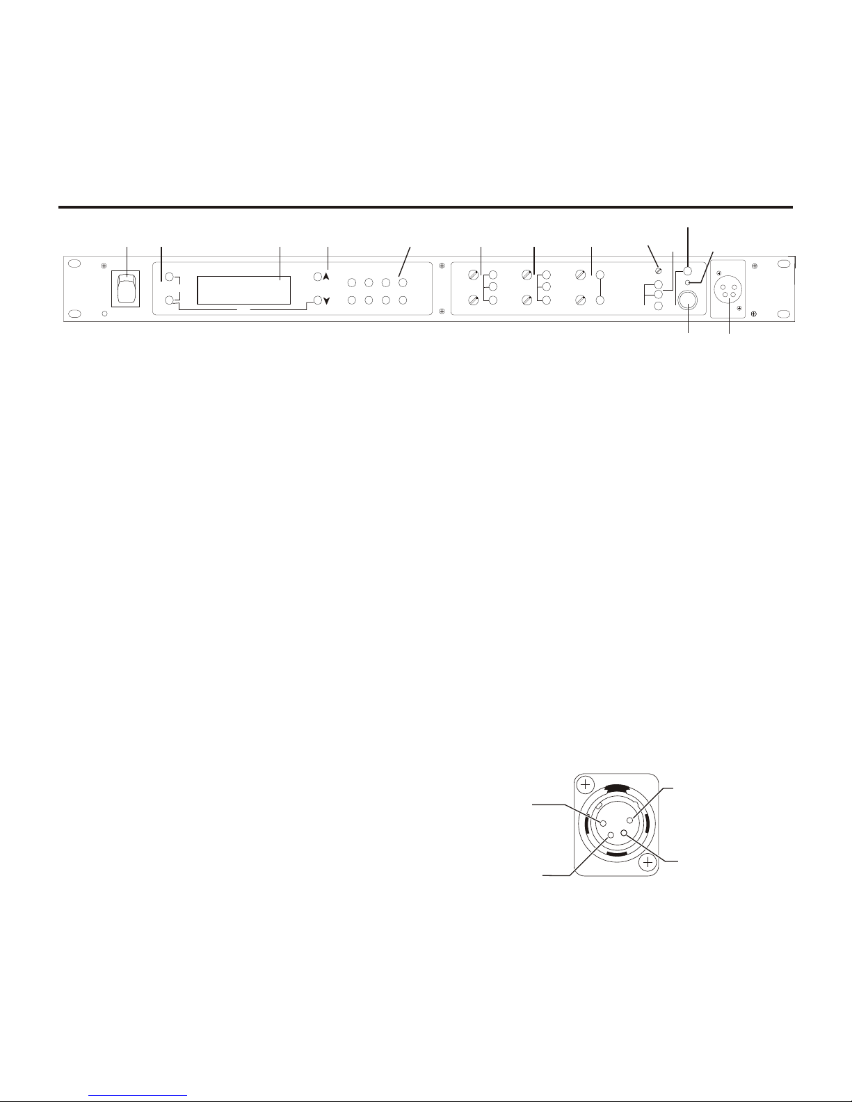
WBS-680 - Front Panel
Section
2
WBS-680 Base Sta tion
Fig ure 1
1. Power switch.
2. [Menu] and [Set] but tons – Used to se lect menus and set
op tions on the LCD.
3. Backlit Graph ics LCD (Liq uid Crys tal Dis play).
4. [Up] and [Down] but tons – Used to se lect base sta tion
op tions on the LCD.
5. Por ta ble Sta tion Con nect – But tons used to en able or
dis able the re spec tive re ceiver’s au dio. GREEN LED =
Au dio en abled, LED OFF = Au dio dis abled.
6. In ter com A Con trols - Wired in ter com A in ter face con trols. Au dio in put and out put level con trols. 2-wire or
4-wire se lect but ton with green LED in di ca tor lights. Se lected LED will change to RED if the in put lev els are too
high.
7. In ter com B Con trols - Wired in ter com B in ter face con trols. Au dio in put and out put level con trols. 2-wire or
4-wire se lect but ton with green LED in di ca tor lights. Se lected LED will change to RED if the in put lev els are too
high.
11. Tal k /Overmod Light – LED is green when talk but ton
#13 is ac tive. A nor mal mic gain set ting will cause the
LED to flash red on the loud est speech lev els. If the gain
is too high, the LED will be red at nor mal speech vol umes.
12. Mi cro phone Gain – Ad justs the head set’s mi cro phone
gain. Ad justs so that the overmod light #11 flashes from
green to red on loud est speech.
13. Talk But ton – Press to en able the au dio path from the lo cal
head set. LED #11 will turn green when en abled. A quick
press and re lease latches but ton on. If the talk func tion is
latched on, press ing the talk but ton again will turn it off.
14. Lo cal Head set Con nec tor – Male XLR con nec tor. A dy namic or electret head set mi cro phone is au to mat i cally de tected.
8. Aux il iary Con trols - Wired aux il iary in ter face con trols.
Au dio in put and out put level con trols. GREEN LED =
Aux. in put en abled. LED will change to RED if the in put
lev els are too high.
9. Head set Vol ume – Con trols the vol ume to the head set
con nected to #14.
10. Head set In ter com Se lect – Con trols the in ter com to
which the lo cal head set is con nected. Each press of the
but ton changes the con nec tion; chan nel A, chan nel B,
both.
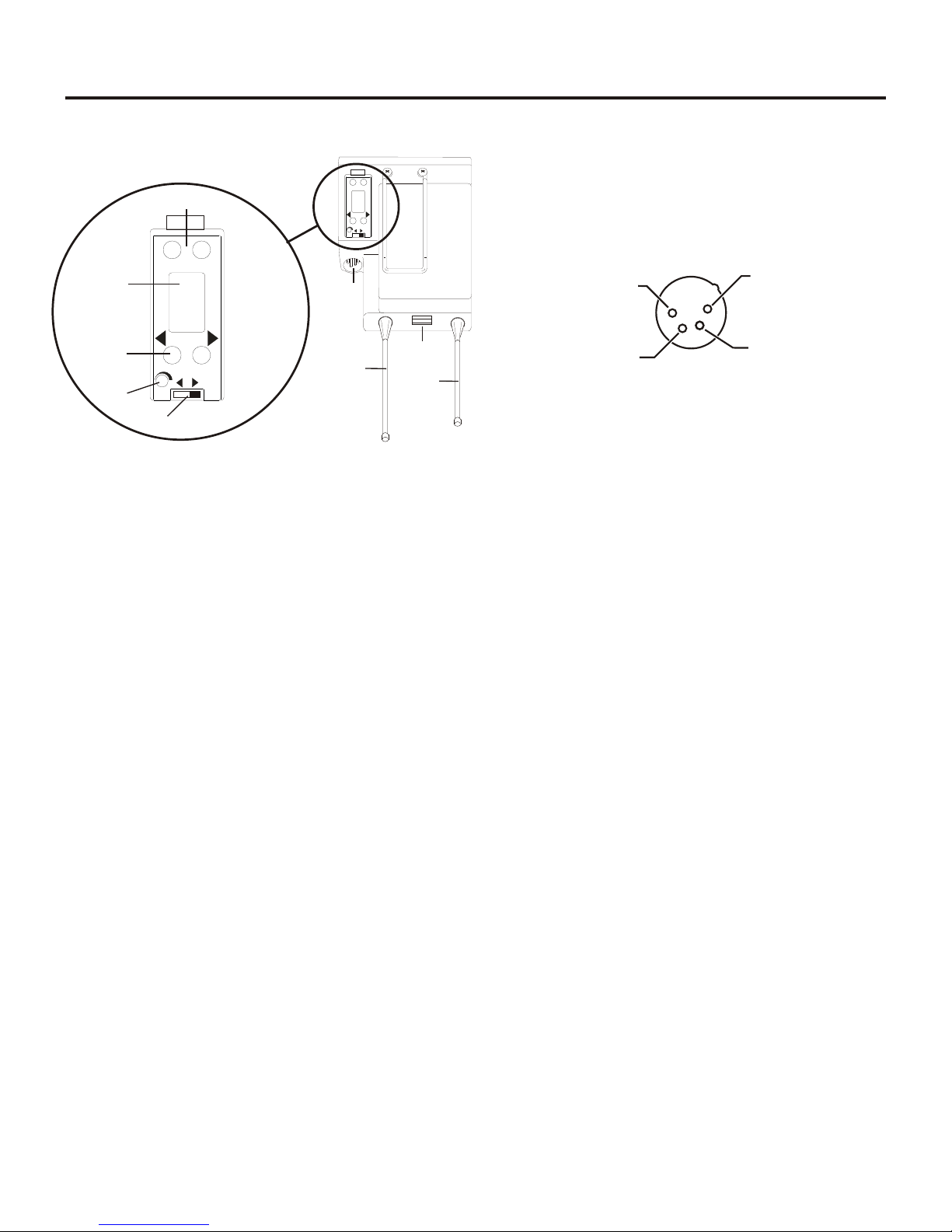
Fig ure 2
Lo cal Head set Wiring
2-1
Page 8

Con trols and Con nec tions - Rear Panel
PUSHPUSHPUSH
1
2
3
4
5
6
7
8
9
10
11
12
RECEIVE
HIGH
ON
NORM
OFF
TRANSMIT
POWER
I/C
TELEX CLEAR-COM
RTS
BASE STATION
LINK
RELAY
CONTACT
INTERCOM A
2-WIRE
L
O
O
P
T
H
R
U
4-WIRE
INTERCOM B
2-WIRE
L
O
O
P
T
H
R
U
4-WIRE
AUXILIARY AUDIO
INPUT OUTPUT
STAGE ANNOUNCE
OUTPUT
POWER
100-240 VAC 50-60 Hz
TRANSMIT
MADE IN USA
WBS-680
FCC ID: B5DM514
CANADA 1321231218A
R
Intercom Systems
WBS-680 - Rear Panel
Fig ure 3
1. Re ceive An tenna - Fe male “TNC” Con nec tor. Color band
on an tenna must match color dot on base sta tion.
2. Trans mit Power Switch – HIGH = Trans mit ters at full
power. NOR MAL = Trans mit ters 10dB be low full power.
3. Trans mit ON/OFF Switch – Turns the trans mit ters on or off.
4. I/C Se lect Switch – Set to the ap pro pri ate 2-wire in ter com
type be ing in ter faced to the unit. Set to ei ther Clear-Com,
Telex, or RTS.
5. Base Sta tion Link Jack – When two base sta tions are
con nected through this jack, it al lows wire less talk around
(WTA) from the beltpacks to be routed from the sys tem
with it’s trans mit ters off to the sys tem with it’s trans mit ters
on.
6. Re lay Con tact – A dry con tact clo sure which is ac ti vated
when a beltpack user presses the stage an nounce (SA) but ton. Normally Open (NO). One amp at 24V max i mum.
7. In ter com A – In ter face to wired in ter com sys tem A.
2-Wire – Male and fe male 3-pin XLR con nec tors
wired in par al lel. The con nec tors are switched to the
ap pro pri ate in ter com con fig u ra tion via the I/C Se lect
Switch.
8. In ter com B – In ter face to wired in ter com sys tem B.
2-Wire – Male and fe male 3-pin XLR con nec tors
wired in par al lel. The con nec tors are switched to the
ap pro pri ate in ter com con fig u ra tion via the I/C Se lect
Switch.
4-Wire – An RJ-45 type jack com pat i ble with “Ma trix” type in ter com sys tems.
9. Aux il iary In put/Out put – One 3-pin fe male XLR in put
con nec tor and one 3-pin male XLR out put con nec tor.
10. Stage An nounce Out put – Passes the au dio from any of
the base sta tion’s beltpacks that have se lected stage an nounce (SA).
11. Power – IEC re cep ta cle. Ac cepts 100 – 240 VAC, 50 – 60 Hz.
12. Trans mit An tenna - Fe male “TNC” Con nec tor. Color
band on an tenna must match color dot on base sta tion.
4-Wire – An RJ-45 type jack com pat i ble with “Ma trix” type in ter com sys tems.
2-2
Page 9

WBS-680
Spec i fi ca tions
Over all
RF Fre quency Range ......................518 - 608 MHz, 614 - 740 MHz in 18 MHz TX and RX bands
Power Re quire ments .......................................100-240 VAC, 50-60 Hz, IEC re cep ta cle
Tem per a ture Range ..............................................-4° F to 130° F (-20° C to 55° C)
Di men sions .............................19.00” W x 1.72” H x 14.00” D (48.3 cm x 4.4 cm x 35.6 cm)
Weight ...................................................................7 lbs 2 oz (3.24 kg)
TX An tenna .............................................½ Wave (sup plied), TNC Male Con nec tor
RX An tenna .............................................½ Wave (sup plied), TNC Male Con nec tor
FCC ID: .........................................................................B5DM514
Fre quency Re sponse..............................................................300Hz-8kHz
Four-Wire In put ................................................Level Ad just able (2 Vrms typ i cal)
Four-Wire Out put ...............................................Level Ad just able (2 Vrms typ i cal)
Clear-Com In ter com............... In put/Out put Level Ad just able (1 Vrms typ i cal), Line Im ped ance 200W
Telex In ter com....................In put/Out put Level Ad just able (1 Vrms typ i cal), Line im ped ance 300W
RTS In ter com .................In put/Out put Level Ad just able (0.775 Vrms typ i cal), Line Im ped ance 200W
Aux il iary In put ......................................................Ad just able (2 Vrms typ i cal)
Aux il iary Out put ............................................Ad just able (2 Vrms typ i cal into 600W)
Stage An nounce Out put ................In ternally Ad just able (2 Vrms typ i cal at rated de vi a tion into 600W)
Stage An nounce Re lay .......................................Dry con tact, rated at 1 Amp, 24V Max
Mi cro phone in put sen si tiv ity .............................................................9mV
Lo cal Head set Out put ......................................40mW out put into 600W (1% Dis tor tion)
Trans mit ter
Type .............................................Two Syn the sized Trans mit ters, 712 chan nels each
Trans mit Power (each trans mit ter) .............................100 mW Max. (High), 10 mW (Nor mal)
Mod u la tion Type........................................................................FM
De vi a tion ...........................................................................40 kHz
RF Fre quency Sta bil ity ................................................................0.005%
Mod u la tion Lim iter ................................................Peak-Responding Com pres sor
Ra di ated Har monics & Spu ri ous ........................................Ex ceeds FCC spec i fi ca tions
Re ceiver
Type..........Dual Con ver sion Super het ero dyne, four In de pend ent Syn the sized IFs, FM, 712 chan nels each
RF Sen si tiv ity........................................................<0.8 µV for 12 dB SINAD
Squelch Thresh old ..............................................................20 dB SINAD
IF Se lec tiv ity.................................................................3 dB at 230 kHz
Im age Re jec tion ...............................................................70 dB or better
Squelch Quieting......................................................................90 dB
RF Fre quency Sta bil ity ................................................................0.005%
Dis tor tion ...............................................................<1% at full de vi a tion
2-3
Page 10

2-4 Blank
Page 11
Con trols and Con nec tions - Top Panel
SA
WTA
A B
CHANNEL
BAT/OM TALK
TALK
1
2
4
5
6
7
3
Vol
Off
Section
3
WTR-680 Beltpack
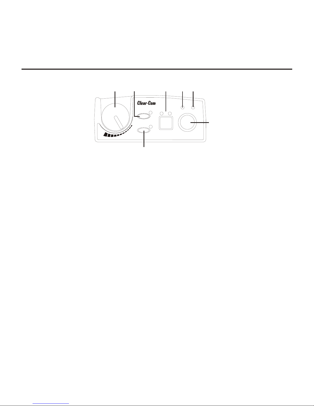
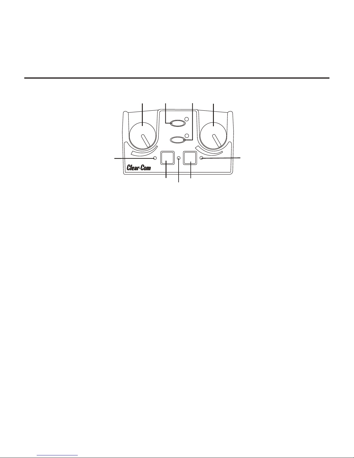
Fig ure 4
WTR-680 Top Panel
1. On/Off & Vol ume Con trol – Turns the beltpack power
on and con trols head set vol ume.
2. Wire less Talk Around (WTA) – When pressed, the user’s
au dio is dis con nected from the wired in ter com, aux il iary
in put/out put and the base sta tion’s lo cal head set. Other
beltpack us ers, on that au dio chan nel, can hear the user as
nor mal. The but ton ac ti vates the nearby red LED as well
as the “TALK” LED, #6, when pressed.
3. Stage An nounce (SA) –When pressed, the user’s au dio is
routed to the stage an nounce con nec tor on the back of the
base sta tion. The user also loses their sidetone as an in di ca tion that stage an nounce is ac ti vated. The other wire less
beltpacks and wired us ers do not hear the user’s au dio.
The but ton is non-latching and ac ti vates the nearby red
LED as well as the “TALK” LED, #6, when pressed.
4. Au dio Chan nel – Al lows user to se lect ei ther au dio
chan nel A or B.
5. Bat/Overmod Light – Light will flash once when unit is
turned on if the bat tery is good. If the light stays on, bat tery is low. If the light does not flash, bat tery is dead. A
nor mal mi cro phone gain set ting will cause the LED to
flash at the be gin ning of most words at nor mal speech lev els. If the gain is too high, the LED will be red dur ing the
com plete word at nor mal speech lev els.
6. Talk Light – LED is on when the talk but ton, SA or WTA
is ac tive.
7. Tal k But ton – Press to en able the au dio path from the lo cal head set mi cro phone. The “TALK” LED, #6, will turn
red when en abled. A quick press and re lease latches the
talk func tion, un less latch ing has been dis abled. Holding
the but ton for over ½ a sec ond will cause the au dio path to
be en abled only for as long as the but ton is held. If the talk
func tion is latched on, press ing the talk but ton again will
turn it off.
3-1
Page 12
Con trols and Con nec tions - Rear Panel
MENU
SET
M
I
C
P
T
T
X
PT
T
A
LK
6
7
8
9
MENU
SET
M
I
C
P
T
TX
PT
T
AL
K
2
1
3
4
5
(1) Microphone
Shield (-)
(2) Microphone
Audio (+)
(4) Headphone
Low (-)
(3) Headphone
High (+)
Fig ure 6
Head set Jack Wiring
WTR-680 Rear Panel/Con nec tor/An tennas
1. [MENU] and [SET] but tons – Used to se lect menus and
set op tions on the LCD.
2. LCD (Liq uid Crys tal Dis play)
3. [UP] and [DOWN] but tons – Used to se lect beltpack op -
tions on the LCD.
4. Mi cro phone Gain – Ad justs the head set’s mi cro phone
gain. Ad just so that the BAT/OM LED will flash at the be gin ning of most words at nor mal speech lev els.
5. Push-to-Talk/Push-to-Transmit Switch –
Push-to-Talk (PT TALK) – The trans mit ter is al ways
on. No au dio sent un less the talk switch, WTA or SA
but ton pressed. Rec om mended po si tion.
Push-to-Transmit (PT TX) - The trans mit ter and au dio path are off ex cept when the talk switch, WTA or
SA but ton is pressed.
Fig ure 5
6. Head set Con nec tor – Male XLR con nec tor. A dy namic or
electret head set mi cro phone is au to mat i cally de tected by
the beltpack and a bias volt age sup plied if needed.
7. Bat tery Latch – Press down to en able the bat tery pack to
be re leased. While the latch is held down, slide the bat tery
pack about 1/8 inch back, to ward the latch, un til it stops.
Then lift out.
8. Re ceive An tenna – Screw type ¼-wave re place able an tenna. The re ceiver an tenna is al ways the lon ger an tenna.
Color dot on the screw end of the an tenna must match
color dot on an tenna re cep ta cle.
9. Trans mit An tenna – Screw type ¼-wave re place able an tenna. Color dot on the screw end of the an tenna must
match color dot on an tenna re cep ta cle.
3-2
Page 13

WTR-680
Spec i fi ca tions
RF Fre quency Range ......................518 - 608 MHz, 614 - 740 MHz in 18 MHz TX and RX bands
Power Re quire ments........................................6 “AA” Cells Al ka line (NiMH op tional)
Cur rent Draw ...................................................140 mA (Push-to-Talk, Talk On)
Tem per a ture Range ..............................................-4° F to 130° F (-20° C to 55° C)
Di men sions .................................3.75”W x 5.05”H x 1.65” D (9.5 cm x 12.8 cm x 4.2 cm)
Weight ......................................................16 oz (454g) with al ka line batteries
TX An tenna ...........................................¼ Wave (sup plied), Screw type, Replaceable
RX An tenna ...........................................¼ Wave (sup plied), Screw type, Replaceable
FCC ID: .........................................................................B5DM515
Fre quency Re sponse..............................................................300Hz-8kHz
Mi cro phone in put sen si tiv ity .............................................................7 mV
Lo cal Head set Out put ......................................40 mW out put into 600W (1% dis tor tion)
Trans mit ter
Type ...............................................................Syn the sized, 712 chan nels
Trans mit Power ..............................................50 mW Max. (auto-power reduction)
Mod u la tion Type........................................................................FM
De vi a tion ...........................................................................40 kHz
RF Fre quency Sta bil ity ................................................................0.005%
Mod u la tion Lim iter ................................................Peak-Responding Com pres sor
Ra di ated Har monics & Spu ri ous ........................................Ex ceeds FCC spec i fi ca tions
Re ceiver
Type ...............................Dual Con ver sion Super het ero dyne, Syn the sized, FM, 712 chan nels
RF Sen si tiv ity........................................................<0.7 µV for 12 dB SINAD
Squelch Thresh old .................................................20 dB SINAD (About 1.0 µV)
IF Se lec tiv ity.................................................................3 dB at 230 kHz
Im age Re jec tion ...............................................................70 dB or better
Squelch Quieting......................................................................90 dB
RF Fre quency Sta bil ity ................................................................0.005%
Dis tor tion ...............................................................<1% at full de vi a tion
3-3
Page 14

3-4 Blank
Page 15
Con trols and Con nec tions - Top Panel
Vol
Off
SA
WTA
TALK
Vol
Off
TALK
A B
Bat/
OM
1
2
3
1
6
6
4
4
5
Section
4
WTR-682 Beltpack
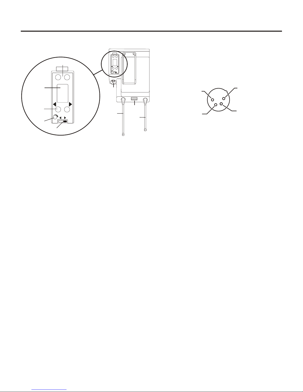
Fig ure 7
WTR-682 Top Panel
1. On/Off and Vol ume Con trol - Turns beltpack power on
and con trols head set vol ume for In ter com Chan nels “A”
and “B”. Ei ther knob, “A” or “B”, turns the beltpack on.
Both knobs must be off to turn the beltpack off. If only
one knob is off, then only that In ter com Chan nel, “A” or
“B” is off for both trans mit and re ceive au dio.
2. Wire less Talk Around (WTA) - When pressed, the user’s
au dio is dis con nected from the wired in ter com, aux il iary
in put/out put and the base sta tion’s lo cal head set. Other
beltpack us ers, on that au dio chan nel, can hear the user as
nor mal. The de fault set ting is soft ware selectable, as to
which In ter com Chan nel, “A”, “B”, “A + B”, or cur rently
se lected chan nel, is ac ti vated along with the “WTA” but ton. The “WTA” but ton ac ti vates the nearby red LED as
well as the soft ware se lected In ter com Chan nel “TALK”
LED if not al ready ac tive.
3. Stage An nounce (SA) - When pressed, the user’s au dio is
routed to the stage an nounce con nec tor on the back of the
base sta tion. The user also loses their sidetone as an in di ca tion that stage an nounce is ac ti vated. The other wire less
beltpacks and wired us ers do not hear the user’s au dio.
The but ton is non-latching and ac ti vates the nearby red
LED.
4. Talk But ton - Press to en able the au dio path to ei ther In ter com Chan nel “A” or “B” or “A + B”, from the lo cal
head set mi cro phone. The as so ci ated “TALK” LED, #6,
will turn red when en abled. A quick press and re lease
latches the talk func tion, un less latch ing has been dis abled. Holding the but ton for over ½ sec ond, will cause
the au dio path to be en abled only for as long as the but ton
is held. If the talk func tion is latched on, press ing the talk
but ton again will turn it off.
5. Low Bat tery/Overmodulation (BAT/OM) Light - Light
will flash once when unit is turned on if the bat tery is
good. If the light stays on, bat tery is low. If the light does
not flash, bat tery is dead. A nor mal mi cro phone gain set ting will cause the LED to flash at the be gin ning of most
words at nor mal speech lev els. If the gain is too high, the
LED will be red dur ing the com plete word at nor mal
speech lev els.
6. Talk Light - Will turn red when en abled by as so ci ated
“TALK” or “WTA” but ton.
4-1
Page 16
Con trols and Con nec tions - Rear Panel
MENU
SET
M
I
C
P
T
T
X
P
T
T
A
L
K
6
6
7
7
8
8
9
9
MENU
SET
M
IC
PT
T
X
PT
TA
L
K
2
2
1
1
3
3
4
4
5
5
(1) Microphone
Shield (-)
(2) Microphone
Audio (+)
(4) Headphone
Low (-)
(3) Headphone
High (+)
Fig ure 8
WTR-682 Rear Panel/Con nec tor/An tennas
1. [MENU] and [SET] but tons – Used to se lect menus and
set op tions on the LCD.
2. LCD (Liq uid Crys tal Dis play)
3. [UP] and [DOWN] but tons – Used to se lect beltpack op -
tions on the LCD.
4. Mi cro phone Gain – Ad justs the head set’s mi cro phone
gain. Ad just so that the BAT/OM LED will flash at the be gin ning of most words at nor mal speech lev els.
5. Push-to-Talk/Push-to-Transmit Switch –
Push-to-Talk (PT TALK) – The trans mit ter is al ways
on. No au dio sent un less the talk switch, WTA or SA
but ton pressed. Rec om mended po si tion.
Push-to-Transmit (PT TX) - The trans mit ter and au dio path are off ex cept when the talk switch, WTA or
SA but ton is pressed.
Fig ure 9
Head set Jack Wiring
6. Head set Con nec tor – Male XLR con nec tor. A dy namic or
electret head set mi cro phone is au to mat i cally de tected by
the beltpack and a bias volt age sup plied if needed.
7. Bat tery Latch – Press down to en able the bat tery pack to
be re leased. While the latch is held down, slide the bat tery
pack about 1/8 inch back, to ward latch, un til it stops. Then
lift out.
8. Re ceive An tenna – Screw type ¼-wave re place able an tenna. The color dot on the screw end of the an tenna must
match color dot on an tenna re cep ta cle.
9. Trans mit An tenna – Screw type ¼-wave re place able an tenna. The color dot on the screw end of the an tenna must
match color dot on an tenna re cep ta cle.
4-2
Page 17

WTR-682
Spec i fi ca tions
RF Fre quency Range ......................470 - 608 MHz, 614 - 746 MHz in 18 MHz TX and RX bands
Power Re quire ments........................................6 “AA” Cells Al ka line (NiMH op tional)
Cur rent Draw ............................................190 mA (Push-to-Talk, A and B Talk On)
Tem per a ture Range ..............................................-4° F to 130° F (-20° C to 55° C)
Di men sions .................................3.75”W x 5.35” H x 2.02” D (9.5 cm x 13.5 cm x 5.1 cm)
Weight ......................................................21 oz (595g) with al ka line bat ter ies
TX An tenna ...........................................¼ Wave (sup plied), Screw type, Re place able
RX An tenna ...........................................¼ Wave (sup plied), Screw type, Re place able
FCC ID: .........................................................................B5DM517
Fre quency Re sponse..............................................................300Hz-8kHz
Mi cro phone in put sen si tiv ity .............................................................7 mV
Lo cal Head set Out put ......................................40 mW out put into 600W (1% dis tor tion)
Trans mit ter
Type ...............................................................Syn the sized, 712 chan nels
Trans mit Power ..............................................50 mW Max. (auto-power re duc tion)
Mod u la tion Type........................................................................FM
De vi a tion ...........................................................................40 kHz
RF Fre quency Sta bil ity ................................................................0.005%
Mod u la tion Lim iter ................................................Peak-Responding Com pres sor
Ra di ated Har monics & Spu ri ous ........................................Ex ceeds FCC spec i fi ca tions
Re ceiver
Type ..................Two, Dual Con ver sion Super het ero dyne Receivers, Syn the sized, FM, 712 chan nels
RF Sen si tiv ity........................................................<0.8 µV for 12 dB SINAD
Squelch Thresh old .................................................20 dB SINAD (About 1.0 µV)
IF Se lec tiv ity.................................................................3 dB at 230 kHz
Im age Re jec tion ...............................................................70 dB or better
Squelch Quieting......................................................................90 dB
RF Fre quency Sta bil ity ................................................................0.005%
Dis tor tion ...............................................................<1% at full de vi a tion
4-3
Page 18

4-4 Blank
Page 19

Un packing
Section
5
Ini tial Equip ment Set-Up
Un pack your Clear-Com Sys tem. Be low are the items that
should come with your base sta tion and each belt pack.
Quan tity De scrip tion
WBS-680
1 WBS-680 Base Sta tion
1 Op er ating Instructions
1 Power Cord
2 An tennas (one Trans mit and one Re ceive)
1 Warranty Card
1 Screwdriver
1 2-terminal plug (for SA Re lay)
1 Warranty Card
4 Rub ber feet
Con tact the ship per or your dealer im me di ately if any thing is
dam aged or miss ing.
WTR-680,
WTR-682
Quan tity De scrip tion
1 WTR-68X with Antennas
1 Bat tery pack
1 In struc tion Sheet
1 Screwdriver
1 Warranty Card
5-1
Page 20
An tenna Con nec tion
T
e
l
e
x
W
T
A
A
B
O
F
F
B
A
T
/
O
M
T
A
L
K
VOL
SA
TALK
Gain
Volume
SELECT
A
B
On/off
In
Out
AUXILIARYINTERCOM B
2-Wire
4-Wire
Select
In
Out
2-Wire
4-Wire
Select
In
Out
INTERCOM A
BELTPACK CONNECT
1 234
Up
Down
Menu
Set
Clear-Com
SCAN
Copy
WBS-680
R
WTR-680
T
e
l
e
x
W
T
A
A
B
O
F
F
B
A
T
/
O
M
T
A
L
K
VOL
SA
R
WTR-680
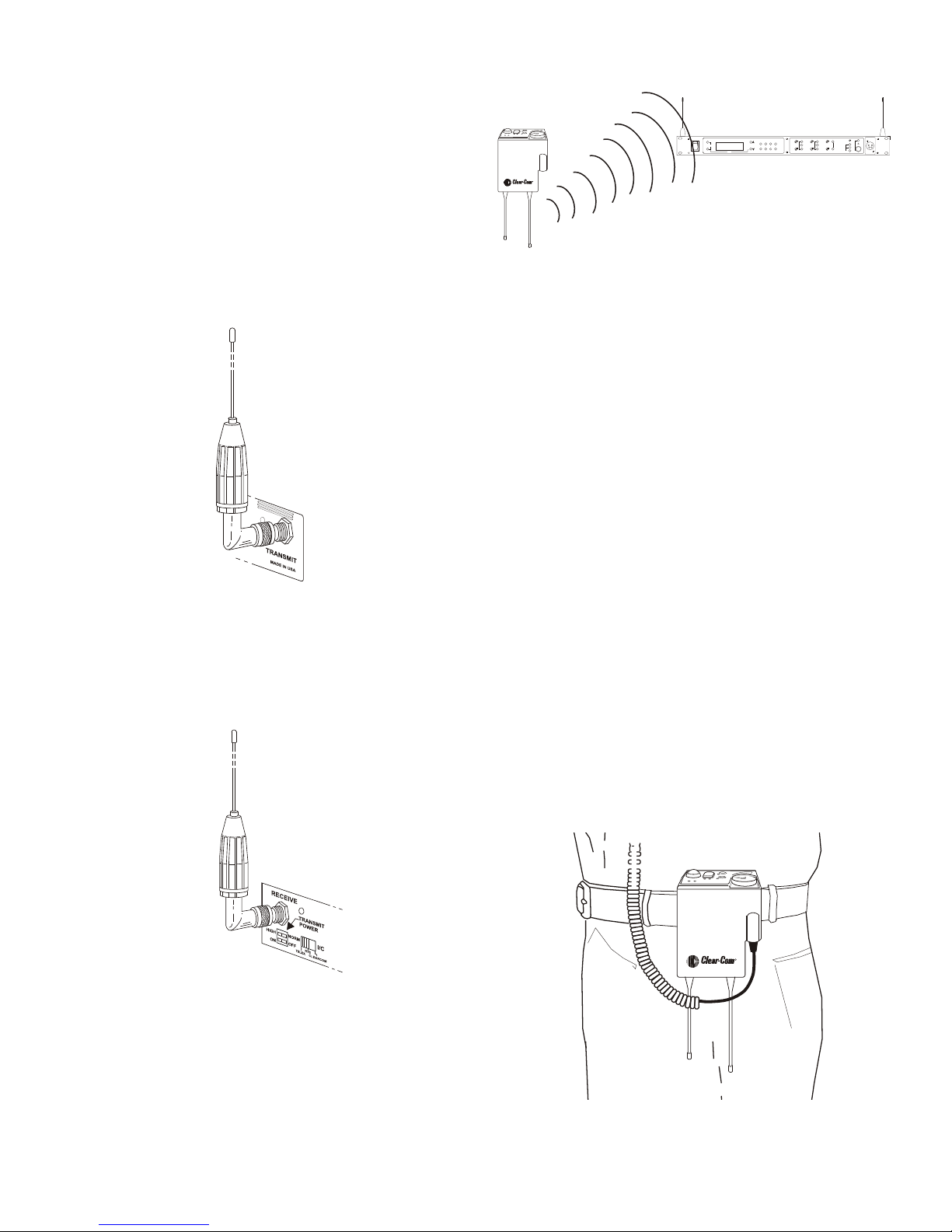
The base sta tion is sup plied with two (2) an ten nas. One
1/2-wave an tenna for Trans mit and one 1/2-wave for Re ceive.
The an ten nas have TNC male con nec tors.
The fre quency range of the an ten nas should match the re ceiver
and trans mit ter of the base sta tion. Match the color code on
the an tenna with the color code on the base sta tion.
At tach the trans mit 1/2-wave an tenna to the an tenna in put re --
cep ta cle la beled “Trans mit” on the right side of the rear panel.
The an tenna should be ver ti cally aligned.
ANTENNAS SHOULD BE VERTICAL
Fig ure 12
Ver ti cally Po lar ized An tennas
Dis tance Be tween An tennas
The dis tance be tween the base sta tion’s re ceive and trans mit
an ten nas is not ad just able when the an ten nas are con nected di --
rectly on the back of the unit.
The an ten nas can be remoted for better sig nal path.
NOTE: If your base sta tion is to be lo cated in a shielded rack
mount en clo sure or other poor RF lo ca tion, you must re mote
the 1/2-wave an ten nas with coax as sem blies.
Fig ure 10
Attaching Trans mit 1/2-Wave An tenna
At tach the re ceive 1/2-wave an tenna to the an tenna in put re --
cep ta cle la beled “Re ceive” on the left side of the rear panel.
The an tenna should be ver ti cally aligned.
Fig ure 11
Attaching Re ceive 1/2-Wave An tenna
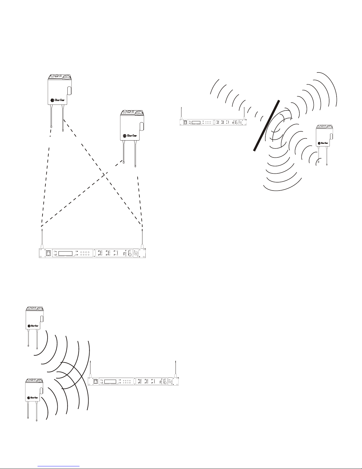
An tenna Place ment
Proper an tenna place ment prob a bly has the most ef fect on
your Wire less In ter com Sys tem’s over all per for mance. The
fol low ing sug ges tions will re sult in op ti mum per for mance.
Proper place ment of the beltpack can be crit i cal. The an ten nas
should be in the open. Bending the an ten nas up and plac ing
the beltpack in a pocket, etc., will re duce sys tem dis tance.
It is sug gested that the unit be worn on the belt or pocket with
both an tenna’s ver ti cal for best op er at ing range and per for --
mance.
An tenna Po lar iza tion
The Wire less In ter com Sys tem is “Ver ti cally Po lar ized”. This
means both the trans mit ting and re ceiv ing an ten nas should op --
er ate in the ver ti cal po si tion.
Fig ure 13
Proper Dress ing of the An tenna
5-2
Page 21
Keep the dis tance be tween the base sta tion and the beltpacks
700 FEET
100 FEET
T
e
l
e
x
W
T
A
A
B
O
F
F
B
A
T
/
O
M
T
A
L
K
VOL
SA
T
e
l
e
x
W
T
A
A
B
O
F
F
B
A
T
/
O
M
T
A
L
K
VOL
SA
TALK
Gain
Volume
SELECT
A
B
On/off
In
Out
AUXILIARYINTERCOM B
2-Wire
4-Wire
Select
In
Out
2-Wire
4-Wire
Select
In
Out
INTERCOM A
BELTPACK CONNECT
1 234
Up
Down
Menu
Set
Clear-Com
SCAN
Copy
WBS-680
R
WTR-680
R
WTR-680
T
e
l
e
x
W
T
A
A
B
O
F
F
B
A
T
/
O
M
T
A
L
K
VOL
SA
T
e
l
e
x
W
T
A
A
B
O
F
F
B
A
T
/
O
M
T
A
L
K
VOL
SA
TALK
Gain
Volume
SELECT
A
B
On/off
In
Out
AUXILIARYINTERCOM B
2-Wire
4-Wire
Select
In
Out
2-Wire
4-Wire
Select
In
Out
INTERCOM A
BELTPACK CONNECT
1 234
Up
Down
Menu
Set
Clear-Com
SCAN
Copy
WBS-680
R
WTR-680RWTR-680
R
WTR-680RWTR-680
T
e
l
e
x
W
T
A
A
B
O
F
F
B
A
T
/
O
M
T
A
L
K
VOL
SA
TALK
Gain
Volume
SELECT
A
B
On/off
In
Out
AUXILIARYINTERCOM B
2-Wire
4-Wire
Select
In
Out
2-Wire
4-Wire
Select
In
Out
INTERCOM A
BELTPACK CONNECT
1 234
Up
Down
Menu
Set
Clear-Com
SCAN
Copy
WBS-680
R
WTR-680RWTR-680
as short as pos si ble. The greater the dis tance, the weaker the
sig nal. Make sure the “sig nal paths” be tween the base sta tion
and beltpacks are un ob structed. You should be able to vis i bly
lo cate the base sta tion an ten nas at all times for best per for --
mance.
At tempting to op er ate the wire less in ter com sys tem through or
around walls, ceil ings, metal ob jects, etc. will re duce sys tem
range and per for mance.
Fig ure 16
Op er ating Sys tem Near Ob struc tions
DO NOT - mount the base sta tion 1/2-wave an ten nas on, or
next to metal, such as beams, walls with metal studs, equip --
ment racks, etc. This also ap plies to the an ten nas when as sem --
bled di rectly to the Base Sta tion. This will “de tune” the
an ten nas which can re sult in noise or loss of RF sig nal at the
Dis tance Be tween base sta tion and beltpack
Fig ure 14
Base Sta tion, see Fig ure 17.
Fig ure 15
Keeping Site Clear to An tenna
5-3
Page 22
#1
#2
#3
TALK
Gain
Volume
SELECT
A
B
On/off
In
Out
AUXILIARYINTERCOM B
2-Wire
4-Wire
Select
In
Out
2-Wire
4-Wire
Select
In
Out
INTERCOM A
BELTPACK CONNECT
1 234
Up
Down
Menu
Set
Clear-Com
SCAN
Copy
WBS-680
TALK
Gain
Volume
SELECT
A
B
On/off
In
Out
AUXILIARYINTERCOM B
2-Wire
4-Wire
Select
In
Out
2-Wire
4-Wire
Select
In
Out
INTERCOM A
BELTPACK CONNECT
1 234
Up
Down
Menu
Set
Clear-Com
SCAN
Copy
WBS-680
TALK
Gain
Volume
SELECT
A
B
On/off
In
Out
AUXILIARYINTERCOM B
2-Wire
4-Wire
Select
In
Out
2-Wire
4-Wire
Select
In
Out
INTERCOM A
BELTPACK CONNECT
1 234
Up
Down
Menu
Set
Clear-Com
SCAN
Copy
WBS-680
TALK
Gain
Volume
SELECT
A
B
On/off
In
Out
AUXILIARYINTERCOM B
2-Wire
4-Wire
Select
In
Out
2-Wire
4-Wire
Select
In
Out
INTERCOM A
BELTPACK CONNECT
1 234
Up
Down
Menu
Set
Clear-Com
SCAN
Copy
WBS-680
TALK
Gain
Volume
SELECT
A
B
On/off
In
Out
AUXILIARYINTERCOM B
2-Wire
4-Wire
Select
In
Out
2-Wire
4-Wire
Select
In
Out
INTERCOM A
BELTPACK CONNECT
1 234
Up
Down
Menu
Set
Clear-Com
SCAN
Copy
WBS-680
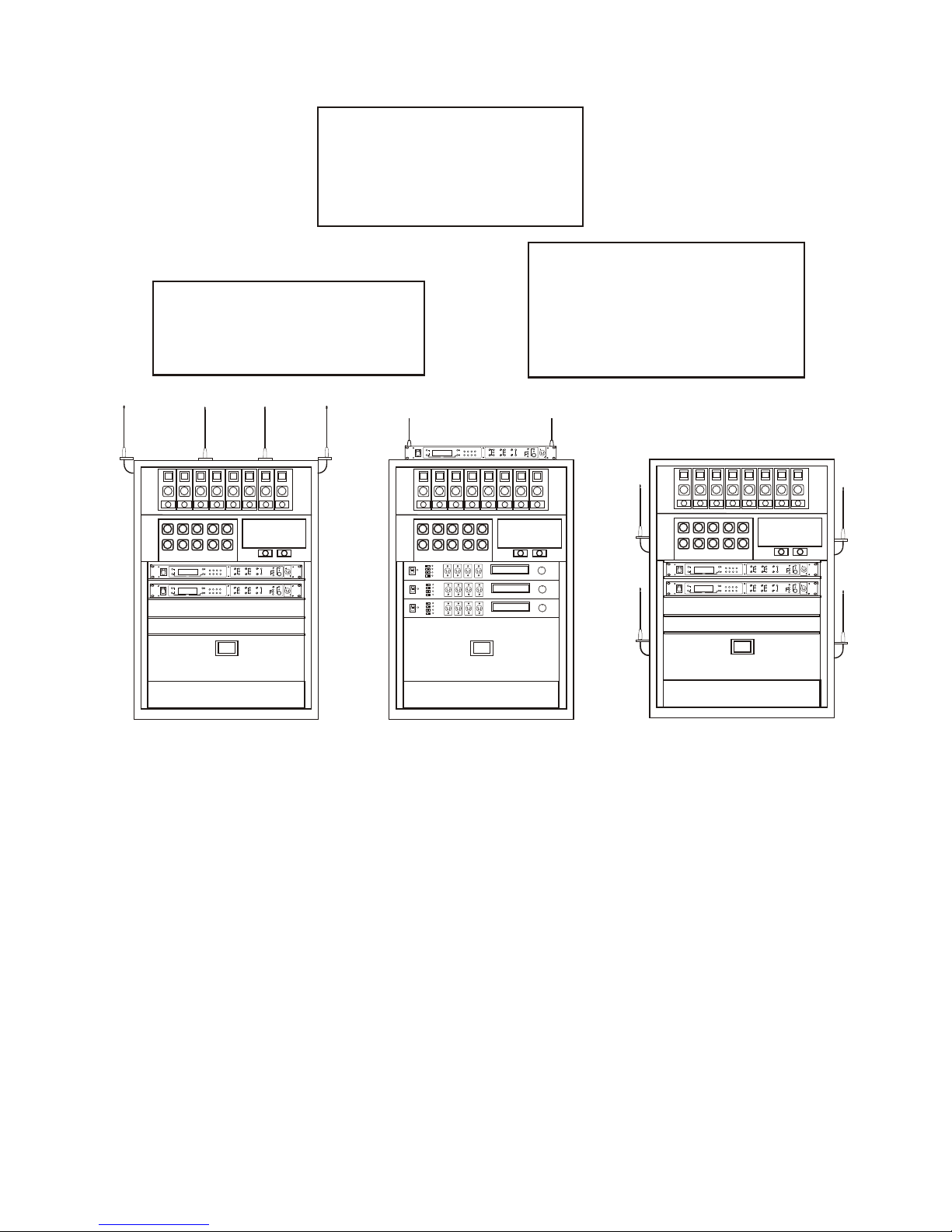
2. Placing the WBS's on top of
a shelf or equip ment rack
un ob structed with out
remoting the an ten nas is
OK.
1. Placing WBS's in a shelf or
equip ment rack and us ing re mote an ten nas is OK.
3. Placing WBS's in a shelf or
equip ment rack with the an ten nas mounted on the back
of the WBS or the side of
the rack is BAD.
Improving Re cep tion and In creasing
Range
Keeping the dis tance from the base sta tion and beltpack as
short, and un ob structed as pos si ble will pro duce the most re li --
able per for mance.
Fig ure 17
An tenna Place ment
The base sta tion is sup plied with two an ten nas. This should
pro vide sat is fac tory sys tem per for mance in most ap pli ca tions.
Sys tem range can be en hanced by remoting the 1/2-wave an --
ten nas.
5-4
Page 23
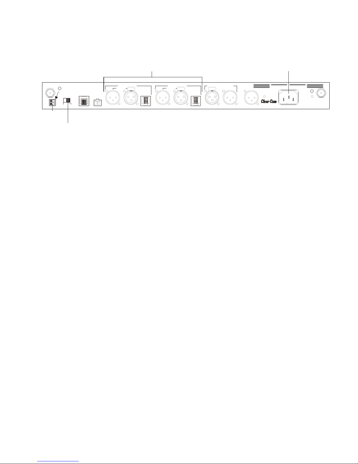
Base Sta tion Set-up
TRANSMIT
SWITCHES
INTERCOM
SWITCH
INTERCOM
INTERFACE
POWER CONNECTION
PUSHPUSHPUSH
RECEIVE
HIGH
ON
NORM
OFF
TRANSMIT
POWER
I/C
TELEX CLEAR-COM
RTS
BASE STATION
LINK
RELAY
CONTACT
INTERCOM A
2-WIRE
L
O
O
P
T
H
R
U
4-WIRE
INTERCOM B
2-WIRE
L
O
O
P
T
H
R
U
4-WIRE
AUXILIARY AUDIO
INPUT OUTPUT
STAGE ANNOUNCE
OUTPUT
POWER
100-240 VAC 50-60 Hz
TRANSMIT
MADE IN USA
WBS-680
FCC ID: B5DM514
CANADA 1321231218A
R
Intercom Systems
Fig ure 18
Base Sta tion - Rear Panel
Lo ca tion
Lo cate the base sta tion with the front and rear of the unit ac --
ces si ble so that switches may be set and con nec tions made.
Place the trans mit and re ceive an ten nas on the base sta tion.
Make sure the an tenna’s color band match the color dot near
each an tenna. See “An tenna In for ma tion” sec tion for more in --
for ma tion on choos ing a proper op er at ing lo ca tion.
Power Con nec tion
Plug the sup plied power cord into the unit. The base sta tion has
an IEC power re cep ta cle that ac cepts 100 – 240 VAC, 50 – 60
Hz. The spe cific re cep ta cle type is an IEC 60320/C14. The cord
it ac cepts is an IEC 60320/C13. These cords are com mon and
avail able through many re tail hard ware/elec tronic stores if the
cord is lost.
Trans mit Switches
There are two switches lo cated on the lower left side of the rear
panel. The up per switch sets the trans mit power lev els to high
or nor mal. The lower switch turns the trans mit ters on or off.
Trans mit Power
Set the power level to nor mal if us ing the beltpacks at
close to me dium dis tances (<200 feet, 161m,
line-of-sight) from the base sta tion. Set the power level to
high if us ing the beltpacks at a dis tance (>200 feet, 161m,
line-of-sight) from the base sta tion.
On/Off
Set the trans mit ter switch to on for nor mal use. In the off
po si tion both base sta tion trans mit ters are dis abled. Set --
ting the switch to off will dis able all the beltpacks from
hear ing any one else or even their own sidetone.
5-5
Page 24
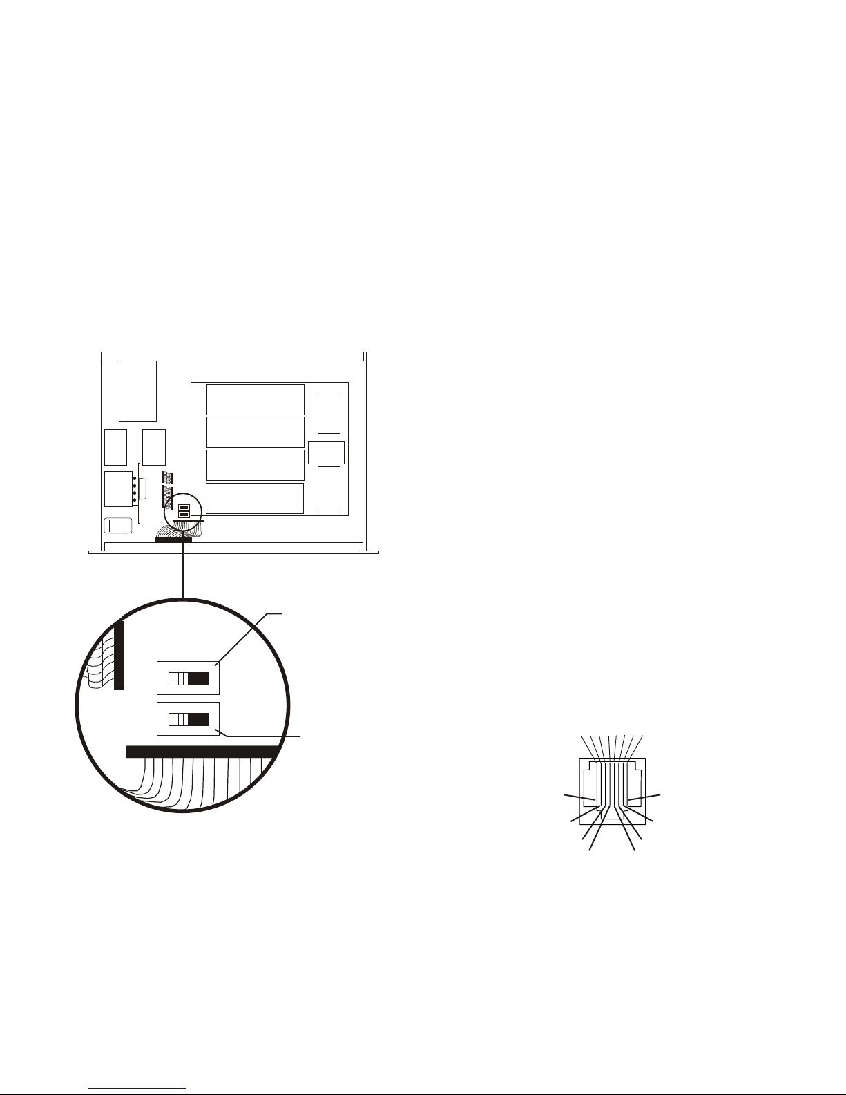
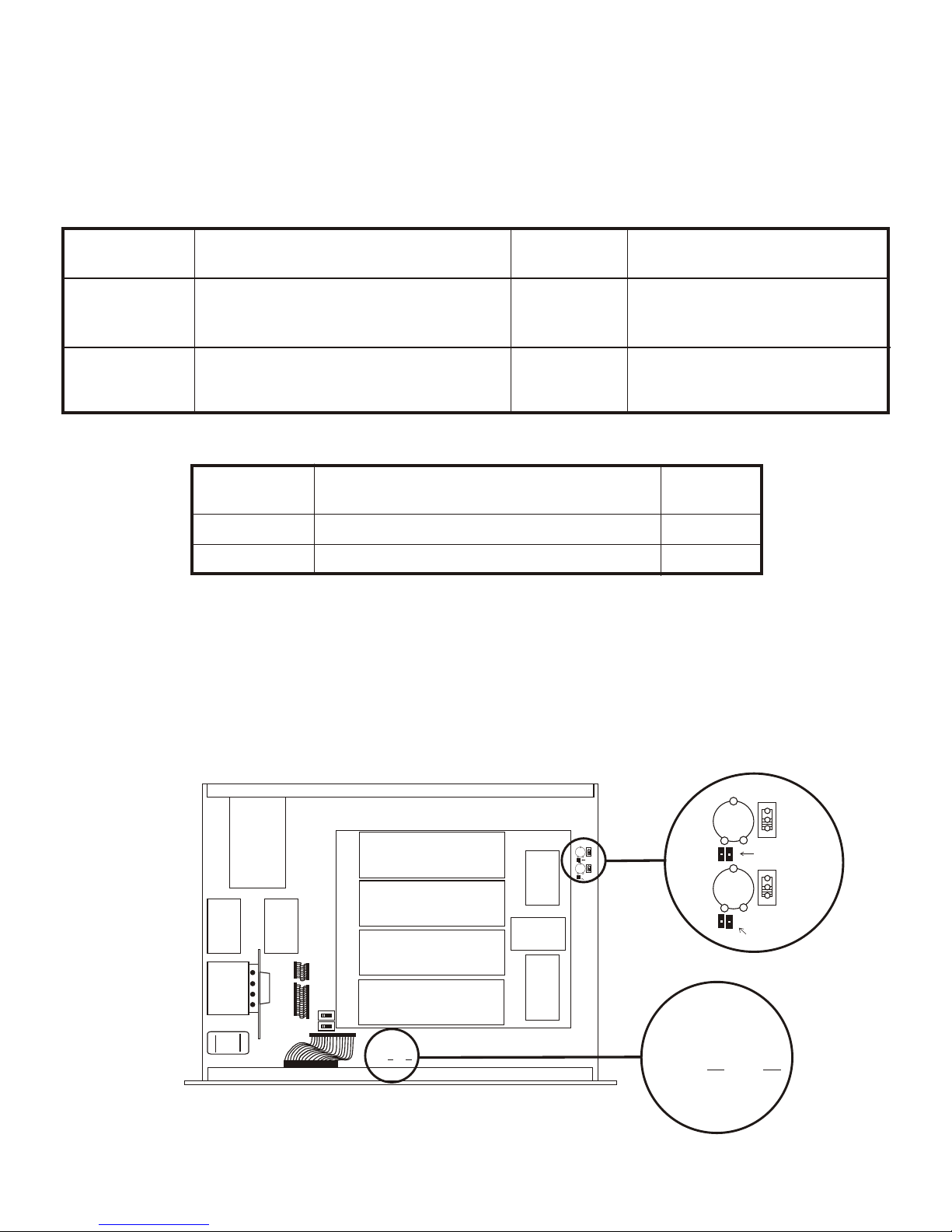
In ter nal Trans mit Switches
ON
ON
S3
OFF
S4
OFF
Transmitter 2
Transmitter 1
FRONT
BACK
PIN 1 2 3 4 5 6 7 8
CONNECTED TO PIN 2
CONNECTED TO PIN 1
AUDIO OUT -
AUDIO IN -
CONNECTED TO PIN 7
CONNECTED TO PIN 8
AUDIO OUT +
AUDIO IN +
In ter com Switch
In ter nal to the WBS-680 are two trans mit switches which en --
able a user to turn on or off the two trans mit ters in di vid u ally.
See Fig ure 19 for the lo ca tion. The top cover of the base
station must be re moved for ac cess. The switch clos est to the
front panel con trols trans mit ter 1 (au dio chan nel A). The
switch be hind that is trans mit ter 2 (au dio chan nel B). The de --
fault switch po si tion is to the left if you are fac ing the front of
the base sta tion. This is the “ON” po si tion for the trans mit ters.
In the nor mal use of the WBS-680, there is no need to ac cess
these switches. They are used to test the trans mit ters in di vid u --
ally at the fac tory.
The Clear-Com Wire less sys tem can be in ter faced to
Clear-Com, RTS, Audiocom® (Telex), Ma trix and other in ter --
com (I/C) sys tems. Set the In ter com switch on the rear of the
unit to the ap pro pri ate sys tem and con nect the sys tem to the
base sta tion. The two in ter com chan nels on the rear of the base
sta tion have loop-thru male and fe male XLR con nec tions for
two-wire sys tems and RJ-45 type jacks for four-wire sys tems.
This switch only af fects the two-wire in ter com sys tems. The
func tions of the I/C XLRs change de pend ing on the in ter com
se lected. Please see Sec tion 12 for pinout in for ma tion of the
dif fer ent two-wire in ter com sys tems.
In ter com In ter face
Clear-Com and Telex (Audiocom®) in ter com sys tems re quire
one ca ble for in ter com A and one ca ble for in ter com B in or --
der to in ter face two chan nels of in ter com to the base sta tion.
This in ter fac ing is done through the I/C A and B 3-pin XLR
con nec tors on the rear of the unit.
RTS TW in ter coms only need to con nect one 3-pin ca ble to
one of the four in ter com XLR con nec tors since two chan nels
of au dio are car ried on one ca ble. The in ter com switch par al --
lels the four XLR con nec tors when in RTS mode. RTS chan --
nel 1 is placed on in ter com A and RTS chan nel 2 is placed on
in ter com B as long as the RTS TW in put to the base sta tion is
wired as in Sec tion 12.
Fig ure 19
In ter nal Trans mit Switches
Four-wire in ter com sys tems re quire one ca ble for in ter com A
and one ca ble for in ter com B in or der to in ter face two chan --
nels of four-wire in ter com to the base sta tion. This in ter fac ing
is done through the I/C A and B RJ-45 type jacks on the rear
of the unit. See Fig ure 20 for the pinout of the RJ-45 jacks.
Fig ure 20
RJ-45 Type/ Four-wire Pinout
5-6
Page 25
Dual Lis ten Func tion al ity
FRONT
BACK
B INTO A
MIX
B INTO A
MIX
OFFOFF
ONONONON
IF PARTS INSTALLED
REMOVE R296
S7S7
S6S6
R296R296
R298R298
VR6VR6
MIX
LEVEL
MIX
LEVEL
OFFOFF
ONONONON
IF PARTS INSTALLED
REMOVE R295
R295R295
R297R297
VR5VR5
MIX
LEVEL
MIX
LEVEL
A INTO B
MIX
A INTO B
MIX
B INTO A
MIX
B INTO A
MIX
OFFOFF
ONONONON
IF PARTS INSTALLED
REMOVE R296
S7S7
S6S6
R296R296
R298R298
VR6VR6
MIX
LEVEL
MIX
LEVEL
OFFOFF
ONONONON
IF PARTS INSTALLED
REMOVE R295
R295R295
R297R297
VR5VR5
MIX
LEVEL
MIX
LEVEL
A INTO B
MIX
A INTO B
MIX
750608 REV X
879416- 1 REV J
750608 REV X
879416- 1 REV J
The base sta tion’s main au dio board has the op tion of plac ing
ad di tional parts to en able dual lis ten. Dual lis ten al lows the
mix ing of the in ter com chan nels. The mix ing will oc cur lo --
cally, within the base sta tion, and is only heard on that base
sta tion's beltpacks. The user will have the abil ity to en able/dis --
able the mix of I/C A into I/C B or vise versa.
They will also have the abil ity to con trol the level of the mix
(-4 dB to -24 dB down from main chan nel). Re moving two
sur face mount re sis tors and in stall ing two SPDT switches and
two po ten ti om e ter en ables dual lis ten. The parts to be in stalled
are shown in Ta ble 1. The two re sis tors on the board to be re --
moved are in Ta ble 2.
Board
Des ig na tor De scrip tion and Func tion Valu e Man u fac turers, Part No.
VR5, VR6 Po ten ti om e ters 20kW - 25kW Bourns, 3309P-1-203
VR5 = Con trols I/C A into I/C B Mix CTS, U262R253B
VR6 = Con trols I/C B into I/C A Mix Piher, PT10LV10-203A2020
S6, S7 Switches SPDT E-Switch, 500ASSP1M2RE
S6 = En able/Dis able I/C A into I/C B Mix E-Switch, EG1218
S7 = En able/Dis able I/C B into I/C A Mix Alcoswitch, TSS11DGPC
Ta b l e 1
Parts to be In stalled by User to En able Dual Lis ten
Board
Des ig na tor De scrip tion and Func tion Valu e
R295 Re sis tor, De fault if mix com po nents not in stalled 10k
R296 Re sis tor, De fault if mix com po nents not in stalled 10k
Parts to be Re moved by User to En able Dual Lis ten
The listed man u fac tures and part num bers in Ta ble 1 are those
that the au dio board was laid out for and thus the hole pat tern
used. Sev eral of these parts may be found at Digi-Key and
other dis trib u tors. Trim the leads on the parts so they can not
hit the metal case. Lo ca tions to place these com po nents are
pro vided on au dio board part num ber 750608.
Ta b l e 2
The au dio board part num ber is lo cated on the lower left hand
side of the board if fac ing the front of the unit. The lo ca tions
where the com po nents can be in stalled are on the up per right
hand side of the board. See Fig ure 21 for the lo ca tions.
Au dio Board Part Num ber and Dual Lis ten Com po nent Lo ca tions
Fig ure 21
5-7
Page 26
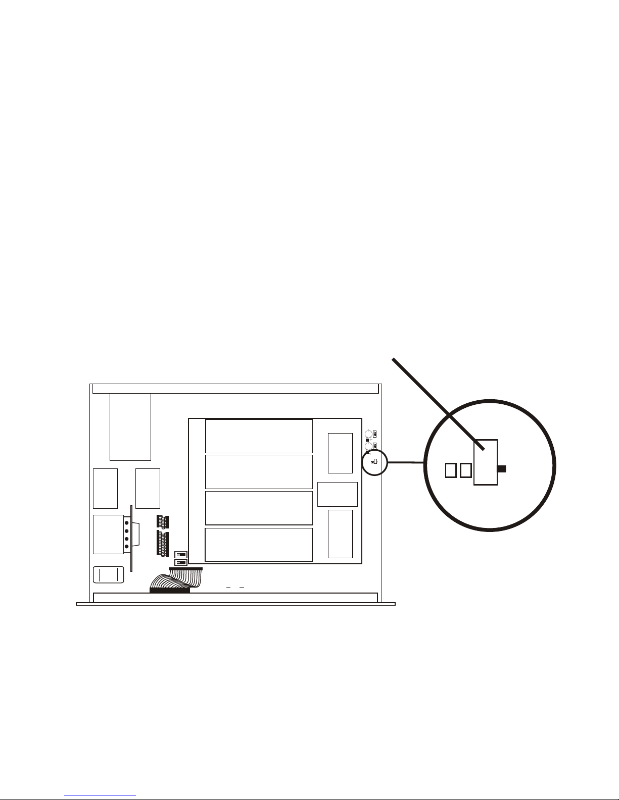
Aux il iary In put/Out put
FRONT
BACK
B INTO A
MIX
B INTO A
MIX
OFFOFF
ONONONON
IF PARTS INSTALLED
REMOVE R296
S7S7
S6S6
R296R296
R298R298
VR6VR6
MIX
LEVEL
MIX
LEVEL
OFFOFF
ONONONON
IF PARTS INSTALLED
REMOVE R295
R295R295
R297R297
VR5VR5
MIX
LEVEL
MIX
LEVEL
A INTO B
MIX
A INTO B
MIX
750608 REV X
879416- 1 REV J
ONON
BB
A & BA & B
AUX INAUX IN
R294R294
R293R293
S5S5
IF PARTS INSTALLED
REMOVE R295
B
A & B
AUX IN
R294
R293
S5
AUXILIARY INPUT
ROUTING SWITCH
The in put and out put 3-pin XLR aux il iary con nec tions are for
sup ply ing ad di tional bal anced au dio into and re ceiv ing bal --
anced au dio from the base sta tion. The out put aux il iary con --
nec tion only in ter faces to in ter com B. How ever, there is an
in ter nal switch to con trol the rout ing of the in put aux il iary au --
dio. See the "In ter nal Aux il iary In put Routing Switch" sec tion
of this man ual.
The in put and out put aux il iary au dio is global. This means
the in put aux il iary au dio is placed on the base lo cal head set,
beltpack(s), head sets, and any wired in ter com sys tem in ter --
faced to the base sta tion. The in ter com chan nel(s) the in put
aux il iary au dio is placed on de pends on the po si tion of the in --
put rout ing switch.
The out put aux il iary au dio is also taken from the in ter com B
base lo cal head set, beltpack(s), head sets, and any wired in ter --
com con nected to the base sta tion. A mod i fi ca tion doc u ment
is avail able from Clear-Com for those who wish to mod ify the
base sta tion so that aux il iary in put au dio is heard only lo cally;
base lo cal head set and beltpack(s) head sets.
In ter nal Aux il iary In put Routing Switch
This switch con trols the rout ing of the in put aux il iary au dio.
This switch has two po si tions. The "B" po si tion places aux il --
iary in put au dio onto in ter com B only (default from fac tory).
The "A & B" po si tion places aux il iary in put au dio onto in ter --
com A and B. Please see Fig ure 22 for the lo ca tion of this in --
ter nal aux il iary in put rout ing switch.
Fig ure 22
Aux il iary In put Routing Switch
5-8
Page 27

Stage An nounce / Re lay Con tacts
AUXILIARY
INTERFACE
STAGE ANNOUNCE
STAGE ANNOUNCE RELAY
PUSHPUSHPUSH
RECEIVE
HIGH
ON
NORM
OFF
TRANSMIT
POWER
I/C
TELEX CLEAR-COM
RTS
BASE STATION
LINK
RELAY
CONTACT
INTERCOM A
2-WIRE
L
O
O
P
T
H
R
U
4-WIRE
INTERCOM B
2-WIRE
L
O
O
P
T
H
R
U
4-WIRE
AUXILIARY AUDIO
INPUT OUTPUT
STAGE ANNOUNCE
OUTPUT
POWER
100-240 VAC 50-60 Hz
TRANSMIT
MADE IN USA
WBS-680
FCC ID: B5DM514
CANADA 1321231218A
R
Intercom Systems
1
2
PHOENIX
TYPE
CONNECTOR
PIN 1
PIN 2
U21
VR4
STAGE ANNOUNCE
LEVEL CONTROL
FRONT
BACK
Base Sta tion - Rear Panel
The stage an nounce out put con nec tor is where au dio ex its the
base when any of the beltpacks press the [SA] but ton. The
out put is bal anced au dio though a male 3-pin XLR. The stage
an nounce out put level is set at the fac tory for 2 Vrms typ i cal
out put at rated de vi a tion into 600 Ohms. This should be ad e --
quate for most ap pli ca tions. There is an in ter nal level ad just --
ment for this out put too. See Fig ure 25 for the lo ca tion of the
small level trim mer. The top cover of the base sta tion must be
re moved for ac cess.
Fig ure 23
Re lay Out put Schematic
A re lay con tact clo sure is also ac ti vated when a beltpack user
presses the [SA] but ton. The con tacts are nor mal open (N.O.).
Rat ing: 1 Amp at 24 volts AC/DC max i mum. A “Phoe nix”
type con nec tor (sup plied) plugs into the re lay con tact port on
the rear of the base sta tion. This con nec tor pro vides a
screw-type clo sure for an easy con nec tion to wires.
Re lay Con tact Jack Adapter
(Screw Ter mi nal Adapter)
Fig ure 24
5-9
Fig ure 25
In ter nal Stage An nounce Level Control
Page 28

Base Sta tion Link
BASE STATION
LINK
PUSHPUSHPUSH
RECEIVE
HIGH
ON
NORM
OFF
TRANSMIT
POWER
I/C
TELEX CLEAR-COM
RTS
BASE STATION
LINK
RELAY
CONTACT
INTERCOM A
2-WIRE
L
O
O
P
T
H
R
U
4-WIRE
INTERCOM B
2-WIRE
L
O
O
P
T
H
R
U
4-WIRE
AUXILIARY AUDIO
INPUT OUTPUT
STAGE ANNOUNCE
OUTPUT
POWER
100-240 VAC 50-60 Hz
TRANSMIT
MADE IN USA
WBS-680
FCC ID: B5DM514
CANADA 1321231218A
R
Intercom Systems
1
2
3
4
5
6
7
8
WTA A+
WTA AWTA B-
WTA B+
1
2
3
4
5
6
7
8
WTA A+
WTA AWTA B-
WTA B+
CABLE: ANY CATEGORY 5 TYPE
CABLE LENGTH: KEEP AS SHORT AS POSSIBLE
RJ-45 MALE
RJ-45 MALE
LOAD LOAD
PUSHPUSHPUSH
RECEIVE
HIGH
ON
NORM
OFF
TRANSMIT
POWER
I/C
TELEX CLEAR-COM
RTS
BASE STATION
LINK
RELAY
CONTACT
INTERCOM A
2-WIRE
L
O
O
P
T
H
R
U
4-WIRE
INTERCOM B
2-WIRE
L
O
O
P
T
H
R
U
4-WIRE
AUXILIARY AUDIO
INPUT OUTPUT
STAGE ANNOUNCE
OUTPUT
POWER
100-240 VAC 50-60 Hz
TRANSMIT
MADE IN USA
WBS-680
FCC ID: B5DM514
CANADA 1321231218A
R
Intercom Systems
Base Sta tion - Rear Panel
This RJ-45 type jack al lows the con nec tion of wire less talk
around (WTA) to two base sta tions. This al lows WTA on I/C
chan nel A and WTA on I/C chan nel B to be the car ried
through to the other base sta tion at tached to gether via this
jack.
WTA chan nel A and chan nel B is “con tained” within a base
sta tion un less the trans mit power is off. If it is off, the WTA
au dio is routed through the base sta tion link ca ble to the other
base that has its trans mit ters on.
A ca ble to ac com plish this task is NOT sup plied, but can eas --
ily be made with com mon cat e gory 5 (CAT-5) wir ing.
In fact, the most com mon 10BaseT ether net patch ca bles,
568-B wired ca bles, can be used to con nect bases to gether.
The re quired ca ble is shown be low.
The reg u lar two-wire in ter com chan nels are passed from base
to base via the wired in ter com ca bles and do not re quire the
base sta tion link ca ble.
Two Stand Alone Base Sta tions Con nected Together
Fig ure 26
Base Sta tion Link Cable
Fig ure 27
5-10
Page 29

Beltpack Set-up
Bat tery In stal la tion
En sure that the On/Off vol ume con trol knob is turned off.
Press down and hold down the bat tery re lease latch, slide the
bat tery pack about 1/8 inch back, to ward latch, un til it stops.
Then lift bat tery pack out. Re place bat ter ies as fol lows:
1. Open the bat tery pack by in sert ing
fin ger nail and lift ing.
2. Pull bat tery strap to re move low
or dead bat ter ies.
3. Load new bat ter ies fol low ing the
po lar ity as shown in bat tery case
4. Start load ing at the end of the case where
the strap is at tached to the case.
5. Be sure strap goes un der bat ter ies.
6. Tuck end of strap un der door
when plac ing the bat tery cover
back on the case.
WARNING
Do not place an al ka line WTR bat --
tery pack in any bat tery charger. Se --
vere charger and bat tery pack
dam age may re sult.
Fig ure 28
Bat tery Installation
5-11
Page 30

An tenna Con nec tion
MENU
SET
M
I
C
P
T
T
X
P
T
T
A
LK
MICROPHONE
GAIN CONTROL
TRANSMIT
SWITCH
HEADSET
CONNECTION
RECEIVE
ANTENNA
TRANSMIT
ANTENNA
BATTERY
RELEASE
LATCH
Fig ure 29
WTR-680 Rear Panel
Head set Con nec tion
The beltpack co mes with two de tach able, screw-type,
1/4-wave an ten nas. To at tach the two an ten nas, screw into the
re cep ta cles at the bot tom of the beltpack. The color dot on the
screw end of the an tenna must match the color dot on an tenna
re cep ta cle. The re ceive an tenna screws into the left re cep ta cle
if the beltpack is lay ing flat with the bat tery com part ment face
up and the an tenna re cep ta cles fac ing you. The other an tenna
is the trans mit an tenna. New an ten nas can be or dered if de --
sired, see the “Ac ces sories” sec tion.
Trans mit mode
The rear panel lo cated trans mit switch has the fol low ing two
modes:
Push-to-Talk (PT TALK) – Rec om mended po si tion –
The trans mit ter is al ways on. No au dio is sent un less the
talk switch, WTA or SA but ton is pressed.
Push-to-Transmit (PT TX) – The trans mit ter and au dio
path are off ex cept when the talk switch, WTA or SA but --
ton is pressed.
In sert the head set plug into the XLR con nec tor. A dy namic or
electret head set mi cro phone is au to mat i cally de tected by the
beltpack and a bias volt age sup plied if needed.
5-12
Page 31

Fol low ing the in struc tions fully to this point you have suc cess --
fully com pleted the fol low ing check list:
Section
6
Pre-Walk-Thru Check list
Lo cated the base sta tion prop erly.
❒
Con nected power to base sta tion.
❒
Con nected the 1/2-wave an ten nas to the base sta tion.
Checked fre quency range of the an ten nas with the fre -
❒
quency of the base sta tion by cor rectly match ing color
codes.
Con nected 1/4-wave an tenna to the beltpack. Checked
fre quency range of the an ten nas with the fre quency of
❒
the beltpack by cor rectly match ing color codes.
Base sta tion trans mit power switches in the cor rect po si tions.
❒
Con nected head sets to base sta tions (if needed) and all
beltpacks.
❒
Con nected the base sta tion to any aux il iary au dio, in ter com, ex ter nal P.A. sys tem, or re lay con tact de tect
❒
cir cuit if needed
In stalled bat ter ies in the beltpack.
❒
If you missed any of the above in struc tions, go back
and com plete that in struc tion be fore go ing on.
❒
Trans mit mode switch on beltpack set cor rectly
❒
Set wired in ter com type cor rectly.
❒
6-1
Page 32

6-2 Blank
Page 33

Section
7
System Op er a tion
Fre quency Plan Over view
The WBS/WTR-680 has 36 fac tory-defined fre quency groups
and 12 user-programmable fre quency groups. A Group de --
fines the two base-station trans mit fre quen cies and thus the
two re ceive fre quen cies on all the beltpacks. A Chan nel de --
fines a base-station re ceive fre quency and thus a beltpack
trans mit frequency. A base-station re ceive chan nel that does
not have a fre quency set for it will have a dash to the right of
it on the Group/Chan nel se lect screen. De tails on set ting fre --
quen cies may be found in the “WBS-680 Menu Struc ture” and
“WTR-680 Menu Struc ture” in struc tions in this sec tion.
Fac tory-Defined Groups
The 36 fac tory-defined groups were care fully cho sen to avoid
cer tain intermod prod ucts and var i ous other pos si ble sources
of in ter fer ence. The Groups are set and can not be changed. A
lim ited num ber of chan nels can be chosen from within these
groups.
The first 24 factory-defined groups (01A – 12B) are “pair”
groups that can be used for sin gle (up to 4 beltpacks) and dual
(up to 8 beltpacks) WBS-680 sys tems. They are ar ranged
01A, 01B, 02A, 02B…011B, 012A, 012B. A “pair” group,
like 1A and 1B, have dif fer ent base-station transmit fre quen --
cies, how ever, they both have the same eight base-station re --
ceive chan nels from which to choose. Each chan nel rep re sents
a unique fre quency. For ex am ple, one WBS-680 could be set
on Group 02A and chan nels 01, 02, 03 and 04. The other
WBS-680 could be set on Group 02B chan nels 05, 06, 07 and
08. As long as the chan nels are dif fer ent, everything should
be fine.
Sys tem Quick Start
Fol low the list be low to quickly get a base sta tion and
beltpack(s) op er at ing. When com pleted the user should have a
base sta tion and 1 to 4 beltpacks up and run ning with full op er --
a tional abil ity. The base sta tion will be on Group 01A with its
four re ceiv ers on chan nels 01, 02, 03 and 04. Each beltpack
will be on Group 01A with a unique trans mit chan nel num ber
match ing one of the base sta tion re ceive chan nels.
1. Plug-in the base sta tion via the sup plied power cord and
con nect the an ten nas. The color dots on the base should
match the color rings on the an ten nas.
2. Base-station rear-panel switches: Trans mit power set to
High and on.
3. En sure base-station rear-panel IC switch matches at tached
wired in ter com sys tem. If used stand alone or con nected to
a 4-wire sys tem then IC switch po si tion is Not Ap pli ca ble.
4. Press [MENU] as pow er ing-up the base sta tion. This will
place it on group 01A and set the re ceives on chan nels: 01,
02, 03, and 04.
5. Place the front-panel IC A and IC B “IN” and “OUT”
level con trols in the 12 o’clock po si tion. Check that
front-panel IC A and B is in 2-wire for Clear-Com,
AudioCom® (Telex), and RTS - TW wired sys tems, and
4-wire for ma trix and stand-alone op er a tion.
6. Place bat ter ies in the beltpacks.
7. Re move the rear switch cover on the beltpacks. Set the
beltpack rear-panel slide switch to push-to-talk (PT
TALK).
The next 12 groups (13 – 24) are sin gle groups that primarily
are used for sin gle (up to 4 beltpacks) WBS-680 sys tems. The
num ber of chan nels from which to choose from in these
groups will vary from group to group.
User-Programmable Groups
The 12 user-programmable groups are ini tially empty. The
trans mit and re ceive fre quen cies are fully editable within these
groups. In fact, fac tory-defined groups may be cop ied to
user-programmable groups and then ed ited if de sired. See the
“WBS-680 Menu Struc ture” and “WTR-680 Menu Struc ture”
in struc tions in this sec tion for de tails on how to copy and edit
fre quen cies.
8. Press [MENU] as pow er ing-up each beltpack. This will
place the beltpack on group 01A with the chan nel 01
flash ing.
9. Use the [UP] and [DOWN] ar row but tons to change the
chan nel to match a channel on the base sta tion. Then press
[SET]. If leav ing on chan nel, just press [MENU]. Each
beltpack should have a unique chan nel num ber.
10. The group/chan nel on the beltpack should now match the
group and a re ceive chan nel on the base sta tion. Noth ing
should be flash ing on the beltpack screens.
11. Plug head sets into the beltpacks and set the mi cro phone
gain so the BAT/OM LED will flash at the be gin ning of
most words at nor mal speech lev els.
DONE.
7-1
Page 34

Base Sta tion Op er a tion
POWER
PORTABLE STATION
CONNECT
INTERCOM
A AND B
AUXILIARY
LOCAL
HEADSET
TALK
Gain
Volume
SELECT
A
B
On/off
In
Out
AUXILIARYINTERCOM B
2-Wire
4-Wire
Select
In
Out
2-Wire
4-Wire
Select
In
Out
INTERCOM A
BELTPACK CONNECT
1 234
Up
Down
Menu
Set
Clear-Com
SCAN
Copy
WBS-680
Base Sta tion - Rear Panel
Power
If you have fol lowed the in struc tions in Sec tion 5, “Ini tial
Equip ment Set-Up”, you should now be ready to turn the base
sta tion on.
Set the base-station power switch to the on po si tion, by push --
ing the top of the switch. The in ter nal cool ing fan will start
im me di ately and the LCD dis play and front-panel in di ca tor
lights will come on in five or six sec onds.
Lo cal Head set
Talk But ton - Press to en able the au dio path from the lo cal
head set. The TALK/O.M. LED will turn green when au dio
is en abled. A quick press and re lease latches on the but ton.
If the talk function is latched on, press ing the talk but ton
again will turn it off. If the lo cal head set is not be ing used,
the talk but ton should be off. This keeps ad di tional noise
out of the sys tem.
Mi cro phone Gain - Ad justs the head set’s mi cro phone
gain. Ad just so the TALK/O.M. LED flashes from green
to red on loudest speech.
Head set In ter com Se lect But ton - Se lect the in ter com
sys tem to con nect to the lo cal head set. Each press of the
[SE LECT] but ton changes the con nec tion: Chan nel A,
Chan nel B, and Both. The cy cle will then re peat. The
LEDs above the [SE LECT] but ton light to in di cate the
cur rent se lec tion.
Vol ume - Ad just the vol ume to the head set by ro tat ing the vol --
ume con trol as re quired for a com fort able lis ten ing vol ume.
Beltpack Con nect
Se lect the au dio paths from the base sta tion’s four re ceiv ers that
you wish to en able. The cor re spond ing LED above the se lect
but ton is on when the au dio path is en abled. If a beltpack user
has their por ta ble sta tion con nect path off at the base, that user
will no lon ger hear their sidetone and their au dio will not be
passed to any one. The user will still be able to hear ev ery one.
The se lec tion is re tained in non-volatile mem ory, so it will
come up where last left if the unit is power cy cled.
Al ways dis able un used au dio re ceive paths. This re duces the
chances that ex ter nal RF noise can get onto the au dio buses
via an open re ceiver.
In ter com A and B
In ter com Se lect But ton - Press the [SE LECT] but ton to
choose be tween 2-wire or 4-wire in ter com sys tems. The
green LED will in di cate the cur rent mode of the in ter com
chan nel. If the base sta tion is con nected to a 2-wire sys --
tem, such as Clear-Com, RTS TW or AudioCom®
(Telex), set the in ter com to 2-wire. If it is con nected to a
four-wire sys tem, such as a ma trix, set the in ter com to
4-wire. It is also pos si ble to have in ter com A con nected
to a 2-wire sys tem and in ter com B con nected to a 4-wire
sys tem or vice versa. The se lec tion is re tained in
non-volatile mem ory, so it will come up where last left if
the unit is power cy cled.
In Level Con trol - Ad justs the au dio level of the wired
in ter com sys tem’s in put to the base sta tion.
Out Level Con trol - Ad justs the au dio level of the base
sta tion’s out put to the wired in ter com sys tem.
If the base sta tion is used stand-alone, with no wired in ter com
sys tem con nected, it must be set in the 4-wire mode. The
2-wire mode re quires that a wired in ter com sys tem or ap pro --
pri ate load be con nected to the in ter com A or B XLRs. If not
loaded, a large gain in crease will take place in the un load in --
ter com chan nel which may be high enough to pro duce a loud
“howl ing” sound.
Aux il iary (In ter com B)
Aux il iary In put Se lect But ton - Press the [SE LECT]
but ton to turn on or off the aux il iary in put to the base sta --
tion. The se lec tion is re tained in non-volatile mem ory, so
it will come-up where last left if the unit is power cy cled.
In Level Con trol - Ad justs the au dio level of the wired
aux il iary sys tem’s in put to the base sta tion.
Out Level Con trol - Ad justs the au dio level of the base
sta tion’s out put to the aux il iary XLR plug.
The aux il iary out put con nects only to in ter com B. It does not
in ter face to in ter com A. The aux il iary in put may be switched
to B in ter com (de fault) or A & B in ter com. See Sec tion 4 for
the lo ca tion of this in ter nally lo cated in put rout ing switch. The
aux il iary out put is al ways avail able at the back panel out put
XLR. It can not be switched on or off like the in put. Both the
in put and out put are bal anced au dio ports.
7-2
Page 35

Dis play Con trast
V
D1101
FRONT
BACK
R1101
The LCD’s (Liq uid Crys tal Dis play) con trast is set from the
fac tory to a stan dard level. How ever it is pos si ble for the user
to ad just the con trast if de sired. The con trast con trol is in ter --
nal to the WBS-680 unit near the front panel. The cover must
be re moved for ac cess to this con trol. Please see Fig ure 30 for
the lo ca tion.
Fig ure 30
LCD Con trast
7-3
Page 36

WBS-680 Menu Struc ture
Operating Screen - Pg. 7-5
Power-Up Screen - Pg. 7-5
Group/Channel Select Screen - Pg. 7-6
[MENU]
Group/Frequency Select Screen - Pg. 7-7
[MENU]
Frequency Edit Screen - Pg. 7-8
[MENU]
(User-Programmed Only)
[MENU]
Action
[MENU]
No Action
[MENU]
+
[SET]
Scan
St
a
rt
-u
p
/Se
ar
c
h
S
c
r
e
e
n
-
P
g
.
7
-9
[MENU]
or
[SET]
Scan Result Screen - Pg. 7-9
[MENU]
Group 03A
44
R1R1
On
On
Off
Ch B
TA A
22
33
T1T1
22
Group 14
44
R1R1
Ch 01
On
On
Ch 02
Ch 03
Ch 04
22
33
T1T1
22
Group 15
44
R1R1
715.000
569.700
568.500
716.700
719.700
721.600
22
33
T1T1
22
Group 25u
Freq Edit
44
Ch1Ch1
705.150
565.350
554.250
707.850
710.100
715.300
22
33
T1T1
22
Group 03A
OK?=[SET]
Next
01 05
02 06
03
04 08
no
t
x
Clear-Com
Scan
C60001
SB30001
Main Screen Flowchart
The fol low ing con tains the base sta tion menu struc ture and
ref er ences the pages in which fur ther de tail of that menu may
be found
Other Spe cial Key Se quences:
Lock out........................7-10
Copy .........................7-10
1st Use De fault .................7-10
Fac tory De fault ..................7-10
Page
NOTE: Pressing [MENU] within a screen af ter ac tion
has oc curred es capes from that ac tion and places the
user at the cur rent screen. Any ed it ing that had been
done since [SET] had been pressed is aborted.
7-4
Page 37

Power-Up Screen
Clear-Com
S
C60001
B30001
Group 03A
T1T1
44
R1R1
tx
On
On
Off
Ch B
TA A
Operating Screen
22
33
T1T1
22
no
This screen is dis played only on power up, first use de -
•
fault, and fac tory de fault.
The 1st up per-right-corner num ber dis plays the base’s
•
soft ware re vi sion. The sin gle ver sion num ber in cre ments
for changes in op er a tional soft ware.
The 2nd up per-right-corner num ber dis plays the base’s
•
chan nel map (fre quency plan) ver sion. The sin gle ver sion
num ber in cre ments for changes in the chan nel map.
Once the power-up screen is dis played, it will change to
•
the op er at ing screen af ter a few sec onds.
Op er ating Screen
Screen is dis played af ter power-up screen.
•
Power-Up Screen
Sys tem will re vert to this screen if no ac tiv ity is de tected
•
on the LCD dis play but tons af ter 3 min utes.
Screen dis plays cur rent sta tus of the sys tem.
•
Beltpack Ac tiv ity Code Def i ni tions:
no tx = No Beltpack Trans mit Car rier De tected
Off = Re ceiver is not se lected on front panel
Ch A = Beltpack au dio is on Channel A
Ch B = Beltpack au dio is on Chan nel B
Ch A&B = Beltpack au dio is on Chan nel A and B (WTR-682 only)
TA A = Beltpack Chan nel B Talk Around Ac tive
TA B = Beltpack Chan nel A Talk Around Ac tive
TA A&B = Beltpack Chan nel A and B Talk Around Ac tive (WTR-682 only)
SA = Beltpack Stage An nounce Ac tive
NOTE: Older ver sions of WBS-680 soft ware do not sup port the de tec tion of WTR-682 “Ch A&B”
and “TA A&B” con trol tones.
7-5
Page 38

Group / Chan nel Se lect
Group 14
T1T1
44
R1R1
Ch 01
On
On
Ch 02
Ch 03
Ch 04
Group / Channel Select
22
33
T1T1
22
Group 14
T1T1
44
R1R1
Ch 01
On
On
Ch 02
Ch 03
Ch 04
22
33
T1T1
22
Group 15
T1T1
44
R1R1
Ch 01
On
On
Ch 02
Ch 03
Ch 04
22
33
T1T1
22
Group 15
T1T1
44
R1R1
Ch 05
On
On
Ch 02
Ch 03
Ch 04
22
33
T1T1
22
[SET]
[UP] / [DOWN]
[SET]
[UP] / [DOWN]
[SET]
Group 15
T1T1
44
R1R1
Ch 05
On
On
Ch 06
Ch 07
Ch 08
22
33
T1T1
22
Group 15
T1T1
44
R1R1
715.000
569.700
568.500
716.700
719.700
721.600
22
33
T1T1
22
[MENU]
[UP] / [DOWN]
[SET] (Last Rx Changed)
END
The Group/Chan nel se lect screen al lows the user to change the
group and se lect from a pre-determined num ber of chan nels
on each re ceiver.
Hit [MENU] once to en ter the Group / Chan nel Se lect
•
Screen from the op er at ing screen.
Hit [SET] to en ter group edit. The group num ber will start
•
flash ing. If [SET] is hit again with out hit ting the ar rows,
the dis play will go to re ceive 01 chan nel edit. NOTE: A
chan nel that does not have a fre quency set for it will have
a dash to the right of it on the group/chan nel se lect screen.
The [UP] / [DOWN] ar rows will change the group num -
•
ber. Hit [SET] again to set the group that was flash ing.
Now the group num ber will stop flash ing and R1’s chan nel num ber will start to flash.
The [UP] / [DOWN] ar rows will change the re ceive chan -
•
nel num ber. Hit [SET] to set the chan nel that was se lected. Now the sec ond chan nel num ber will start to flash.
If [SET] is hit again with out hit ting the ar rows, the dis play will go to the next chan nel num ber.
Af ter the last re ceive chan nel is de cided upon, hit ting
•
[SET] will set that chan nel in the unit and start you over
at the be gin ning of the group/chan nel se lect screen with
noth ing flash ing.
Hit ting [MENU] will take you to the group/fre quency se -
•
lect screen. NOTE: Hit ting [MENU] af ter ac tiv ity has oc -
curred within the screen will re turn to the group/chan nel
se lect screen with noth ing flash ing. Any change that had
been done be fore the last [SET] was pressed will be
aborted.
Set ting two chan nels the same is not al lowed. If a chan nel
•
is al ready set on the screen, the user no lon ger has that
chan nel as an op tion to set into one of the other re ceiv ers.
7-6
Page 39

Group / Fre quency Se lect
Group 15
T1T1
44
R1R1
715.000
569.700
568.500
716.700
719.700
721.600
Group / Frequency Select
22
33
T1T1
22
Group 14
T1T1
44
R1R1
713.200
563.100
561.700
716.100
718.600
721.600
22
33
T1T1
22
Group 14
T1T1
44
R1R1
563.100
561.700
22
33
T1T1
22
Group 14
T1T1
44
R1R1
563.100
561.700
22
33
T1T1
22
[UP] / [DOWN]
[SET]
[UP] / [DOWN]
[SET] (Last Rx Changed)
[UP] / [DOWN]
[SET]
716.100
718.600
721.600
704.200
704.700
708.300
709.500
704.200
Group 14
T1T1
44
R1R1
On
On
22
33
T1T1
22
[MENU]
Ch A
Ch B
no tx
END
no tx
The Group/Fre quency se lect screen al lows a user to set the
group and se lect from a pre-determined num ber of fre quen cies
on each re ceiver. Each fre quency dis played on the right half of
the screen corresponds to a chan nel num ber in the
Group/Chan nel Screen.
Press [MENU] twice to go to the Group / Fre quency Se -
•
lect screen from the op er at ing screen. Hit [SET] to start
the group num ber flash ing.
Press the [UP] / [DOWN] ar rows to change the group
•
num ber. The fre quen cies listed will re flect what is cur rently in that group. Hitting [SET] will se lect the group
and start the se lect ing of pre de ter mined fre quen cies
within that group. The R1 fre quency will start flash ing.
NOTE: The group num ber sets the trans mit fre quen cies
of fac tory de fined groups and these are not editable. In
user-programmed groups these are editable from the fre quency edit screen.
Pressing the [UP] / [DOWN] ar rows will change the fre -
•
quency of “R1” to the pre-defined fre quen cies avail able.
Hitting [SET] will ac cept the change and start you ed it ing
the next chan nel. If you had not hit the ar row keys when
the fre quency was flash ing, but in stead hit [SET], you
would have skipped to the next fre quency to edit.
Af ter the last re ceive fre quency is de cided upon, hit ting
•
[SET] will save that last fre quency and start you over at
the be gin ning of the group/fre quency se lect screen with
noth ing flash ing.
Pressing [MENU] will take you to the op er at ing screen if
•
this is a fac tory-defined group. If within a user pro grammed group, you will be taken to the fre quency edit
screen. NOTE: Hitting [MENU] af ter ac tiv ity has oc curred within the screen will re turn to the group/fre quency edit screen with noth ing flash ing. Any change that
had been done be fore the last [SET] was pressed will be
aborted.
7-7
Page 40

Fre quency Edit
Group 25u
Freq Edit
705.150
565.350
554.250
707.850
710.100
715.300
Group 27u
Freq Edit
705.150
567.800
554.250
707.850
710.100
715.300
Group 27u
Freq Edit
567.800
556.725
Group 27u
Freq Edit
569.350
556.700
[UP] / [DOWN]
[SET]
[UP] / [DOWN]
[SET]
[UP] / [DOWN]
[SET]
707.850
710.100
715.300
705.150
720.550
721.350
721.900
718.550
Group 27u
569.350
556.700
[SET] or [MENU]
(Last Ch Changed)
710.550
714.225
716.800
705.950
END
(User-Programmed Groups Only)
This menu only oc curs for user-programmable groups or when
copy ing to a user-programable group. The Fre quency Edit
screen al lows the user to set the group trans mit fre quen cies
and re ceive chan nel fre quen cies of a user-programmable
group.
Press [MENU] three times to go to the fre quency se lect
•
screen from the op er at ing screen. Press [SET] to start the
group num ber flash ing. This screen al lows the user to set
the group and fre quen cies of user-programmed groups
only.
Fre quency Edit
(User-Programmed Groups Only)
Press the [UP] / [DOWN] ar rows to change the group
•
num ber. The fre quen cies listed will re flect what is cur rently in that group. Dashes will be dis played in any slots
that are not de fined yet. Pressing [SET] will se lect the
group and start the se lect ing of fre quen cies within that
group. The T1 fre quency will start flash ing.
Pressing the [UP] / [DOWN] ar rows will change the fre -
•
quency of “T1” in 25kHz steps. Pressing [SET] will ac cept the change and start you ed it ing T2. If you had not
hit the ar row keys when the fre quency was flash ing, but
in stead press [SET], you would have skipped to the next
fre quency to edit.
Af ter ed it ing the trans mit and the re ceive chan nel fre -
•
quen cies, press ing [SET] will save that last fre quency and
send you over to the be gin ning of the group/fre quency
select screen with noth ing flash ing. NOTE: Once the end
of the dis played chan nel list is reached, the last dis played
chan nel lo ca tion will scroll to al low the user to edit the re main ing chan nels.
Af ter ac tion has oc curred in the fre quency edit screen hit -
•
ting [MENU] will take you one menu back to the
group/fre quency se lect screen so that the user may see
what fre quen cies the base re ceiv ers are now on. If no ac tion had oc curred, then pressing [MENU] will take you to
the op er at ing screen. NOTE: Be sides a group change,
any ed it ing that oc curs within this screen to fre quen cies
DOES NOT take ef fect un til the user ex its the screen via
set ting the last chan nel or press ing [MENU].
7-8
Page 41

Scan
Scan
Group 03A
OK?=[SET]
Next
01 05
02 06
03
04 08
Group 04b 01 05
OK?=[SET]
Prev
Next
06
03
04 08
[DOWN]
[SET]
Group 04b
T1T1
44
R1R1
On
On
22
33
T1T1
22
Ch A
Ch B
TA A
no tx
END
Scan per forms a fre quency scan of the fac tory-defined and any
set-up user-programmable groups in or der to find the group
with the high est num ber of clear re ceive chan nels. Af ter about
20-30 sec onds, the group with the high est num ber of clear re --
ceive chan nels will be dis played. The next best group and so
forth may be ac cessed with the [DOWN] and [UP] arow but --
tons.
Press and hold [MENU] + [SET] for three seconds to en -
•
ter Scan. The base sta tion will now start search ing all
groups for the ones with the great est num ber of re ceiver
chan nels clear of in ter fer ence.
Scan will dis play the group that has the most in ter fer ence
•
free re ceive chan nels. These clear chan nels are dis played
on the right half of the screen. Press [SET] to place the
base sta tion on this group and re turn to the op er at ing
screen. The first four re ceive chan nels dis played will be
the ones set for the group. The [UP] / [DOWN] but tons
may be used to se lect the next best group and so forth.
Scan
7-9
Page 42

Spe cial Key Se quences
Lock out
Press [UP]+[DOWN] for 3 sec onds to lock or un lock the
•
base sta tion. Pressing [MENU] will still func tion to view
screens, but [SET] will no lon ger start any ed it ing. Scan,
First use, Fac tory de fault are no lon ger ac ces si ble. The in ter com chan nel A and B front panel 2-wire/4-wire se lec tion is also locked into place. A pad lock icon will be
dis played on the sec ond line of the dis play to the far left
as an in di ca tion that the base sta tion is locked out.
Copy
Press [SET]+[DOWN] for 3 sec onds to copy any cur -
•
rently dis played group to a user-programmable group.
Copy can be done from the group/chan nel se lect,
group/fre quency se lect or fre quency edit screen. Once
pressed, the words, “Copy to” are dis played on the screen
with the first empty user-programmable group flash ing. If
all the user-programmed groups were full, than the first
programable group is dis played. The [UP] or [DOWN]
but tons may be used to se lect a different user-programmable
group if de sired. Pressing [SET] pastes fre quen cies/chan nels to the group and take the user to the fre quency edit
screen with “T1” flash ing.
1st Use De fault
Press [MENU] while turn ing on the base sta tion to en ter
•
the 1st use de fault setup screen. This places the unit on
group 01A with the four re ceiv ers set to chan nels 1- 4 of
the group. Any user-programmed fre quen cies that had
been en tered pre vi ously are re tained. If lock out had
been ac ti vated, the beltpack co mes up where it was last
left re gard less of [MENU] be ing pressed on power-up.
Fac tory De fault
Pressing all four but tons [MENU]+[SET]+[UP]+[DOWN]
•
at the same time for 3 sec onds places the unit on group
01A with the four re ceiv ers set to chan nels 1 – 4 of that
group. This is just like base sta tion 1st use de fault, ex cept
that all user-programmed fre quen cies that had been en -
tered pre vi ously are erased. This func tion may take sev eral sec onds. If lock out had been ac ti vated, the beltpack
co mes up where it was last left re gard less of these four
keys be ing pressed.
7-10
Page 43

Beltpack Op er a tion
SA
WTA
A B
CHANNELCHANNEL
BAT/OM TALKBAT/OM TALK
TAL K
POWER
LOCAL HEADSET
VOLUME
VolVol
OffOff
WIRELESS
TALK AROUND
(WTA)
BATTERY
CHECK
TAL K
BUTTON
CHANNEL SELECT
BUTTON
STAGE ANNOUNCE
(SA)
MENU
SET
M
IC
P
T
T
X
P
T
T
A
L
K
MICROPHONE
GAIN
VolVol
OffOff
SA
WTA
TALKTALK
VolVol
OffOff
TALKTALK
A B
Bat/OMBat/
OM
TAL K
BUTTON
TAL K
BUTTON
WTR-682
STAGE ANNOUNCE
(SA)
WIRELESS
TALK AROUND
(WTA)
POWER/
LOCAL
HEADSET
VOLUME
POWER/
LOCAL
HEADSET
VOLUME
BATTERY
CHECK
WTR-680
Power / Lo cal Head set Vol ume
Turn the beltpack power on by ro tat ing the knob CW. Ad just
the vol ume to the head set by ro tat ing the vol ume con trol as re --
quired for a com fort able lis ten ing vol ume.
Bat tery Check
When the beltpack power is turned on by ro tat ing the knob,
the BAT/OM LED will flash once if the bat tery is good. If the
LED stays on, the bat tery is low. If the LED does not flash,
the bat tery is dead.
Talk But ton
Press the talk but ton to en able the au dio path from the head set
mi cro phone. The TALK/OM LED will turn red when au dio is
en abled. A quick press and re lease latches the talk func tion
un less latch ing has been disabled. Holding the but ton for over
½ a sec ond will cause the au dio path to be en abled only for as
long as the but ton is held. If the talk func tion is latched on,
press ing the talk but ton again will turn it off. See the “Talk
But ton Latching/Non-Latching” instructions in Sec tion 7 to
learn how to en able/dis able latch ing of the talk but ton.
Mi cro phone Gain
Ad justs the head set’s mi cro phone gain. Ad just so the TALK/OM
LED flashes red at the be gin ning of most words at nor mal speech
lev els. If the in put is too large, the LED will be red dur ing the
com plete word at nor mal speech level. The peak-responding au --
dio lim iter in the beltpack is very tol er ant of high in put au dio lev --
els. Even when the mi cro phone gain is max i mized, and head set
vol ume re duced to make up for the louder au dio, the au dio will
still sound good and not clipped.
Fig ure 31
WTR-680 and WTR-682 Top and Rear Panel
Chan nel Se lect But ton
Se lects the in ter com sys tem to which the head set is con nected.
The LED above the chan nel but ton in di cates the cur rent se lec --
tion. See the “Au dio Chan nel A/B En able/Dis able” in struc --
tions in Sec tion 7 to learn how to en able only chan nel A,
chan nel B, or both.
Stage An nounce (SA)
When pressed the au dio from the beltpack is routed di rectly to
the stage an nounce con nec tor on the back of the base sta tion.
The base sta tion’s SA re lay is also closed. The beltpack
sidetone is lost as an in di ca tion that stage an nounce is ac ti --
vated. The other beltpacks and wired us ers do not hear this
beltpacks au dio when SA is pressed. The but ton is
non-latching and ac tives the nearby red LED as well as the
“talk” LED when pressed. See the “Stage An nounce En --
able/Dis able” instructions in Sec tion 7 to learn how to en --
able/dis able the SA but ton.
Wire less Talk Around (WTA)
When pressed, the au dio from the beltpack is dis con nected
from the wired in ter com, aux il iary in put/out put and the base
sta tion’s lo cal head set. Other beltpack us ers, on that au dio
chan nel, can hear the user as nor mal. The but ton ac tivates the
nearby red LED as well as the talk LED when pressed. See the
“Wire less Talk Around En able/Dis able” in struc tions in Sec --
tion 7 to learn how to en able/dis able the WTA but ton as well
as turn on and off the latch ing func tion.
7-11
Page 44

WTR-680 Menu Struc ture
[MENU]
S10001
c60001
03A 01
Power-Up Screen - Pg. 7-13
Group/Channel Screen - Pg. 7-14
GP CH
[MENU]
704.700
Transmit Screen - Pg. 7-15
TX
[MENU]
554.250
R1
[MENU]
565.350
R2
Receive 1 Screen - Pg. 7-16
Receive 2 Screen - Pg. 7-17
Clr Scn
GP
04b Scn
GP
[MENU]
+
[SET]
Scan Search Screen - Pg. 7-18
Scan Result Screen - Pg. 7-18
[MENU]
or
[SET]
Beltpack Menu Struc ture
The fol low ing con tains the main beltpack menu struc ture and ref er --
ences the pages in which fur ther de tail of that menu may be found.
All beltpack fea tures and spe cial key se quences can only be done
from the group/channel screen.
Beltpack Fea ture En able/Dis able Menus:
Page
Stage An nounce (SA) En able/Dis able .........7-19
Wire less Talk Around (WTA) En able/Dis able ...7-19
Au dio Chan nel A/B Enable/Dis able...........7-20
Talk But ton Latching/Non-Latching...........7-20
Other Spe cial Key Se quences:
Page
Lock out ................................7-21
1st Use De fault ...........................7-21
Fac tory De fault ..........................7-21
NOTE: Pressing [MENU] within a screen af ter ac tion has oc curred es capes
from that ac tion and places the user at the cur rent screen. Any ed it ing that
had been done since [SET] had been pressed is aborted.
7-12
Page 45

WTR-680 Menu Struc ture
END
S10001
c60001
03A 01
GP CH
Power-Up Screens
The first screens dis played when the beltpack is pow ered
•
up are the soft ware and chan nel map ver sion screens.
The 1st screen dis played in di cates the beltpack’s soft ware
•
ver sion num ber. It is dis played for about one sec ond.
The 2nd screen dis played in di cates the beltpack’s chan nel
•
map (fre quency plan) ver sion num ber. It is dis played for
about one sec ond.
The fi nal screen dis played is the group/chan nel screen
•
Power-Up Screens
7-13
Page 46

WTR-680 Menu Struc ture
03A 01
CH
03A 01
GP
03A 01
CH
03A 01
GP
CH
03A 02
GP
CH
03A 02
GP
CH
05b 02
GP
CH
05b 02
GP
[SET]
[UP]/[DOWN]
[SET]
then [SET] twice more
[UP]/[DOWN]
[SET]
END
Group / Chan nel Screen
The Group/Chan nel screen al lows the user to change the
group and se lect from a pre-determined num ber of trans mit
chan nels.
The screen dis played af ter the beltpack pow er-up screens.
•
Press [SET] to edit the chan nel num ber. The chan nel
•
num ber will start flash ing.
Use the [UP]/[DOWN] ar row but tons to change the chan -
•
nel num ber.
Group / Chan nel Screen
Press [SET] to place the beltpack on the chan nel se lected.
•
Once set is pressed, the beltpack trans mit ter will move to
that fre quency and noth ing will be flash ing. Now press
[SET] twice to en ter group edit.
Use the [UP]/[DOWN] ar row but tons to change the group
•
num ber.
Press [SET] to place the beltpack on the group se lected.
•
Once set is pressed, the unit re turns to the group/chan nel
dis play with noth ing flash ing.
Pressing [SET] once more will start the ed it ing se quence
•
over again. Pressing [MENU] dur ing the group edit will
end ed it ing and send the user back at the group/chan nel
screen with out any changes. This ap plies to chan nel ed it ing too.
7-14
Page 47

WTR-680 Menu Struc ture
[SET]
03A 03
GP CH
704.700
TX
706.500
TX
[UP]/[DOWN]
[SET] IS HELD DOWN
[SET] IS RELEASED
706.500
TX
END
704.700
TX
Trans mit Screen
The Transmit screen al lows the user to set the beltpack trans --
mit fre quency. Fac tory-defined groups will al low only a set
num ber of pre-defined fre quen cies to be se lected.
User-programmable groups will al low the user to change the
fre quency in 25kHz steps.
Press [MENU] once from the group/chan nel screen to ar -
•
rive at the trans mit fre quency screen.
Press [SET] to edit the fre quency. The num ber will start
•
flash ing.
Use the [UP]/[DOWN] ar row but tons to change the fre -
•
quency.
Trans mit Screen
Press [SET] to place the beltpack on the fre quency se -
•
lected. If set is held down, dur ing that time the
group/chan nel is dis played so the user is aware of what
trans mit chan nel the unit has been placed. Once set is re leased, the unit re turns to the trans mit fre quency screen
with noth ing flash ing.
Pressing [SET] once more will start the ed it ing se quence
•
over again. Pressing [MENU] dur ing trans mit fre quency
edit will end ed it ing and send the user back to the trans mit
screen with out any changes.
7-15
Page 48

WTR-680 Menu Struc ture
554.250
[SET]
554.250
R1
R1
566.750
R1
[SET] IS HELD DOWN
27u
GP
[SET] IS RELEASED
END
566.750
R1
[UP] / [DOWN]
Re ceive 1 Screen
The Receive 1 screen al lows the user to set the beltpack re --
ceive 1 fre quency. This cor re sponds to the base sta tion’s trans --
mit 1 fre quency. In fac tory-defined groups re ceive 1 is not
change able. User-programable groups will al low the user to
change the fre quency in 25kHz steps.
Press [MENU] twice from the group/chan nel screen to ar -
•
rive at the re ceive 1 fre quency screen.
(User-Programmable Groups Only) Press [SET] to edit
•
the fre quency. The num ber will start flash ing. Fac tory-defined groups can’t be changed; so press ing set will
do noth ing at this screen. User-programmed groups will
start flash ing and al low the user to change the fre quency
in 25kHz steps.
(User-Programmable Groups Only) Use the
•
[UP]/[DOWN] ar row but tons to change the fre quency.
Re ceive 1 Screen
(User-Programmable Groups Only) Press [SET] to place
•
the beltpack on the fre quency se lected. If set is held
down, dur ing that time the group is dis played so the user
is aware of what group the unit has been placed. Once set
is re leased, the unit re turns to the re ceive 1 fre quency
screen with noth ing flash ing.
(User-Programmable Groups Only) Pressing [SET] once
•
more will start the ed it ing se quence over again. Pressing
[MENU] dur ing re ceive 1 fre quency edit will end ed it ing
and send the user back to the re ceive 1 screen with out any
changes.
7-16
Page 49

WTR-680 Menu Struc ture
565.350
[SET]
565.350
R2
R2
567.850
[SET] IS HELD DOWN
27u
GP
[SET] IS RELEASED
END
567.850
[UP] / [DOWN]
R2
R2
Re ceive 2 Screen
The Re ceive 2 screen al lows the user to set the beltpack re --
ceive 2 fre quency. This cor re sponds to the base sta tion’s trans --
mit 2 fre quency. In fac tory-defined groups re ceive 1 is not
change able. User-programable groups will al low the user to
change the fre quency in 25kHz steps.
Press [MENU] three times from the group/chan nel screen
•
to ar rive at the re ceive 2 fre quency screen.
(User-Programmable Groups Only) Press [SET] to edit
•
the fre quency. The num ber will start flash ing. Fac tory-defined groups can’t be changed, so press ing set will
do noth ing at this screen. User-programmed groups will
start flash ing and al low the user to change the fre quency
in 25kHz steps.
(User-Programmable Groups Only) Use the
•
[UP]/[DOWN] ar row but tons to change the fre quency.
Re ceive 2 Screen
(User-Programmable Groups Only) Press [SET] to place
•
the beltpack on the fre quency se lected. If set is held
down, dur ing that time the group is dis played so the user
is aware of what group the unit has been placed. Once
set is re leased, the unit re turns to the re ceive 2 fre quency
screen with noth ing flash ing.
(User-Programmable Groups Only) Pressing [SET] once
•
more will start the ed it ing se quence over again. Pressing
[MENU] dur ing re ceive 2 fre quency edit will end ed it ing
and send the user back to the re ceive 2 screen with out any
changes.
7-17
Page 50

WTR-680 Menu Struc ture
END
04b 01
GP CH
Clr Scn
GP
04b Scn
GP
[SET]
Scan
Scan per forms a fre quency scan of the fac tory-defined and any
set-up user-programmable groups in or der to find the clear est
group. Af ter about 30 sec onds, the clear est group is dis played.
A group is de fined by re ceive 1 and 2 fre quen cies. The next
best group and so forth may be ac cessed with the [DOWN]
and [UP] ar row but tons.
Press and hold [MENU] + [SET] for three sec onds to en -
•
ter Scan. The beltpack will now start search ing for the
clear est groups. The group sym bol will flash in di cat ing
the beltpack is scan ning for clear groups.
Scan will scan all groups. It will then dis play the 1
•
group it came to that had the clear est re ceive chan nels.
The [UP] / [DOWN] but tons may be used to se lect the
next best group and so forth. Hit [SET] to place the
beltpack on this group and re turn to the group/chan nel
screen.
Scan
st
7-18
Page 51

WTR-680 Menu Struc ture
END
03A 01
GP CH
SA on
SA oFF
RELEASE [SET]
HOLD [SET] AND PRESS [SA]
CONTINUE TO HOLD [SET]
AND PRESS [SA] AGAIN
END
03A 01
GP CH
tA on
HOLD [SET] AND PRESS [WTA]
CONTINUE TO HOLD [SET]
AND PRESS [WTA] AGAIN
CONTINUE TO HOLD [SET]
AND PRESS [WTA] AGAIN
tA oFF
tA Lon
RELEASE [SET]
Stage An nounce En able/Dis able
Press and hold [SET] then press the [SA] but ton to show
•
the SA en able/dis able screen. The cur rent set ting of the
fea ture is dis played on the LCD.
gle the dis play from ON to OFF or back. Re lease the
[SET] but ton to ac cept the cur rent dis played set ting and
re turn to the Group/Chan nel screen.
While con tin u ing to hold [SET] press [SA] again to tog -
•
Wire less Talk Around En able/Disable
Press and hold [SET] then press the [WTA] but ton to
•
show the WTA en able/dis able screen. The cur rent set ting
of the fea ture is dis played on the LCD.
the dis play from on, off, then Lon (latch on). Re lease the
[SET] but ton to ac cept the cur rent dis played set ting and
re turn to the Group/Chan nel screen.
While con tin u ing to hold [SET] press [SA] again to cy cle
•
7-19
Page 52

WTR-680 Menu Struc ture
b on
Disabling Audio Channel A
Ab on
A on
HOLD [SET] AND PRESS [CHAN]
CONTINUE TO HOLD [SET]
AND PRESS [CHAN] AGAIN
END
03A 01
GP CH
RELEASE [SET]
CONTINUE TO HOLD [SET]
AND PRESS [CHAN] AGAIN
l on
HOLD [SET] AND PRESS [TALK]
END
03A 01
GP CH
RELEASE [SET]
CONTINUE TO HOLD [SET]
AND PRESS [TALK] AGAIN
t
l oFF
t
Au dio Chan nel A or B Dis able/En able
Press and hold [SET] then press the [CHAN] but ton to
•
show the chan nel en able/dis able screen. The cur rent set ting of the fea ture is dis played on the LCD.
again to move to the next op tion, only chan nel B on.
While con tin u ing to hold [SET], press the [CHAN] but ton
•
As you con tinue to hold [SET], press the [CHAN] but ton
•
once more to move to the next op tion, only chan nel A on.
If the chan nel but ton was hit once more, the user would
start over at the AB ON screen.
Re lease the [SET] but ton to ac cept the cur rent dis played
•
set ting and re turn to the Group/Chan nel screen.
Talk But ton Latch on/Latch off
Press and hold [SET] then press the [TALK] but ton to
•
show the Talk But ton Latch/Non-Latching screen. The
cur rent set ting of the fea ture is dis played on the LCD dis play.
While con tin u ing to hold [SET] press [TALK] again to
•
tog gle the dis play from on to off or back. Re lease the
[SET] but ton to ac cept the cur rent dis played set ting and
re turn to the Group/Chan nel screen.
7-20
Page 53

WTR-680 Menu Struc ture
Spe cial Key Se quences
Lock out
Press [UP]+[DOWN] for 3 sec onds to lock or un lock the
•
beltpack. The words “Loc on” will be dis played when the
fea ture is ac ti vated, “Loc oFF” will be dis played when the
beltpack is un locked. Pressing [MENU] will still func tion
to view screens, but [SET] will no lon ger start any ed it ing. Scan, First use, Fac tory de fault, and Fea ture en able/dis able are no lon ger ac ces si ble.
1st Use De fault
Press [MENU] while turn ing on the beltpack to en ter the
•
1st use de fault setup screen. This places the unit on group
01A with chan nel 01 flash ing. Any user-programmed
fre quen cies that had been en tered pre vi ously are re tained. The beltpacks must now be set to dif fer ent trans -
mit chan nels us ing the [UP]/[DOWN] but tons. Then
[SET] is hit to place the units on those chan nels. If lock out had been ac ti vated, the beltpack co mes up where it
was last left re gard less of [MENU] be ing pressed on
power-up.
Fac tory De fault
Pressing all four but tons [MENU]+[SET]+[UP]+[DOWN]
•
at the same time for three sec onds places the unit on
group 01A with chan nel 01 flash ing, just like beltpack 1
use de fault, ex cept the all user-programmed fre quen cies
that had been en tered pre vi ously are erased. Af ter the
but tons are re leased, it still may take sev eral sec onds for
the beltpack to re set. The beltpacks must now be set to
dif fer ent trans mit chan nels us ing the [UP]/[DOWN] but tons. Then [SET] is hit to place the units on those chan nels. If lock out had been ac ti vated, the beltpack co mes up
where it was last left re gard less of these four keys be ing
pressed.
st
7-21
Page 54

WTR-682 Menu Struc ture
[MENU]
S30001
c60001
03A 01
Power-Up Screen - Pg. 7-23
Group/Channel Screen - Pg. 7-24
GP CH
[MENU]
704.700
Transmit Screen - Pg. 7-25
TX
[MENU]
554.250
R1
[MENU]
565.350
R2
Receive 1 Screen - Pg. 7-26
Receive 2 Screen - Pg. 7-27
Clr Scn
GP
04b Scn
GP
[MENU]
+
[SET]
ClearScan Search Screen - Pg. 7-29
ClearScan Result Screen - Pg. 7-29
[MENU]
or
[SET]
Ab Add
Audio Output - Pg. 7-28
[MENU]
Beltpack Menu Struc ture
The fol low ing con tains the main beltpack menu struc ture and ref er --
ences the pages in which fur ther de tail of that menu may be found.
All beltpack fea tures and spe cial key se quences can only be done
from the group/channel screen.
Beltpack Fea ture En able/Dis able Menus:
Au dio Out put ............................7-28
Stage An nounce (SA) ......................7-30
Wire less Talk Around (WTA)................7-31
Au dio Chan nel A .........................7-32
Au dio Chan nel B .........................7-33
Other Spe cial Key Se quences:
Lock out ................................7-34
1st Use De fault ...........................7-34
Fac tory De fault ..........................7-34
NOTE: Pressing [MENU] within a screen af ter ac tion has oc curred es capes
from that ac tion and places the user at the cur rent screen. Any ed it ing that
had been done since [SET] had been pressed is aborted.
Page
Page
7-22
Page 55

WTR-682 Menu Struc ture
END
S30001
c60001
03A 01
GP CH
Power-Up Screens
The first screens dis played when the beltpack is pow ered
•
up are the soft ware and chan nel map ver sion screens.
The 1st screen dis played in di cates the beltpack’s soft ware
•
ver sion num ber. It is dis played for about one sec ond.
The 2nd screen dis played in di cates the beltpack’s chan nel
•
map (fre quency plan) ver sion num ber. It is dis played for
about one sec ond. The op er at ing screen is then dis played.
The fi nal screen dis played is the group/chan nel screen
•
Power-Up Screens
7-23
Page 56

WTR-682 Menu Struc ture
03A 01
CH
03A 01
GP
03A 01
CH
03A 01
GP
CH
03A 02
GP
CH
03A 02
GP
CH
05b 02
GP
CH
05b 02
GP
[SET]
[UP]/[DOWN]
[SET]
[UP]/[DOWN]
[SET]
END
Group / Chan nel Screen
The Group/Chan nel screen al lows the user to change the
group and se lect from a pre-determined num ber of trans mit
chan nels.
The screen dis played af ter the beltpack pow er-up screens.
•
Press [SET] to edit the chan nel num ber. The chan nel
•
num ber will start flash ing.
Use the [UP]/[DOWN] ar row but tons to change the chan -
•
nel num ber.
Group / Chan nel Screen
Press [SET] to place the beltpack on the chan nel se lected.
•
Once set is pressed, the beltpack trans mit ter will move to
that fre quency and noth ing will be flash ing. Now press
[SET] twice to en ter group edit.
Use the [UP]/[DOWN] ar row but tons to change the group
•
num ber.
Press [SET] to place the beltpack on the group se lected.
•
Once set is pressed, the unit re turns to the group/chan nel
dis play with noth ing flash ing.
Pressing [SET] once more will start the ed it ing se quence
•
over again. Pressing [MENU] dur ing the group edit will
end ed it ing and send the user back at the group/chan nel
screen with out any changes. This ap plies to chan nel ed it ing too.
7-24
Page 57

WTR-682 Menu Struc ture
[SET]
03A 03
GP CH
704.700
TX
706.500
TX
[UP]/[DOWN]
[SET] IS HELD DOWN
[SET] IS RELEASED
706.500
TX
END
704.700
TX
Trans mit Screen
The Transmit screen al lows the user to set the beltpack trans --
mit fre quency. Fac tory-defined groups will al low only a set
num ber of pre-defined fre quen cies to be se lected.
User-programmable groups will al low the user to change the
fre quency in 25kHz steps.
Press [MENU] once from the group/chan nel screen to ar -
•
rive at the trans mit fre quency screen.
Press [SET] to edit the fre quency. The num ber will start
•
flash ing. Fac tory-de fined groups will al low only a set
num ber of pre-de fined fre quen cies to be se lected.
User-pro gram ma ble groups will al low the user to change
the fre quency in 25kHz steps.
Use the [UP]/[DOWN] ar row but tons to change the fre -
•
quency.
Trans mit Screen
Press [SET] to place the beltpack on the fre quency se -
•
lected. If set is held down, dur ing that time the
group/chan nel is dis played so the user is aware of what
trans mit chan nel the unit has been placed. Once set is re leased, the unit re turns to the trans mit fre quency screen
with noth ing flash ing.
Pressing [SET] once more will start the ed it ing se quence
•
over again. Pressing [MENU] dur ing trans mit fre quency
edit will end ed it ing and send the user back to the trans mit
screen with out any changes.
7-25
Page 58

WTR-682 Menu Struc ture
554.250
[SET]
554.250
R1
R1
566.750
R1
[SET] IS HELD DOWN
27u
GP
[SET] IS RELEASED
END
566.750
R1
[UP] / [DOWN]
Re ceive 1 Screen
The Receive 1 screen al lows the user to set the beltpack re --
ceive 1 fre quency. This cor re sponds to the base sta tion’s trans --
mit 1 fre quency. In fac tory-defined groups re ceive 1 is not
change able. User-programmable groups will al low the user to
change the fre quency in 25kHz steps.
Press [MENU] twice from the group/chan nel screen to ar -
•
rive at the re ceive 1 fre quency screen.
(User-Programmable Groups Only) Press [SET] to edit
•
the fre quency. The num ber will start flash ing. Fac tory-defined groups can’t be changed; so press ing set will
do noth ing at this screen. User-programmed groups will
start flash ing and al low the user to change the fre quency
in 25kHz steps.
(User-Programmable Groups Only) Use the
•
[UP]/[DOWN] ar row but tons to change the fre quency.
Re ceive 1 Screen
(User-Programmable Groups Only) Press [SET] to place
•
the beltpack on the fre quency se lected. If set is held
down, dur ing that time the group is dis played so the user
is aware of what group the unit has been placed. Once set
is re leased, the unit re turns to the re ceive 1 fre quency
screen with noth ing flash ing.
(User-Programmable Groups Only) Pressing [SET] once
•
more will start the ed it ing se quence over again. Pressing
[MENU] dur ing re ceive 1 fre quency edit will end ed it ing
and send the user back to the re ceive 1 screen with out any
changes.
7-26
Page 59

WTR-682 Menu Struc ture
565.350
[SET]
565.350
R2
R2
567.850
[SET] IS HELD DOWN
27u
GP
[SET] IS RELEASED
END
567.850
[UP] / [DOWN]
R2
R2
Re ceive 2 Screen
The Re ceive 2 screen al lows the user to set the beltpack re --
ceive 2 fre quency. This cor re sponds to the base sta tion’s trans --
mit 2 fre quency. In fac tory-defined groups re ceiver 2 is not
change able. User-programmable groups will al low the user to
change the fre quency in 25kHz steps.
Press [MENU] three times from the group/chan nel screen
•
to ar rive at the re ceive 2 fre quency screen.
(User-Programmable Groups Only) Press [SET] to edit
•
the fre quency. The num ber will start flash ing. Fac tory-defined groups can’t be changed, so press ing set will
do noth ing at this screen. User-programmed groups will
start flash ing and al low the user to change the fre quency
in 25kHz steps.
(User-Pro gram ma ble Groups Only) Use the [UP]/[DOWN]
•
ar row but tons to change the fre quency.
Re ceive 2 Screen
(User-Programmable Groups Only) Press [SET] to place
•
the beltpack on the fre quency se lected. If set is held
down, dur ing that time the group is dis played so the user
is aware of what group the unit has been placed. Once set
is re leased, the unit re turns to the re ceive 2 fre quency
screen with noth ing flash ing.
(User-Programmable Groups Only) Pressing [SET] once
•
more will start the ed it ing se quence over again. Pressing
[MENU] dur ing re ceive 2 fre quency edit will end ed it ing
and send the user back to the re ceive 2 screen with out any
changes.
7-27
Page 60

WTR-682 Menu Struc ture
[SET]
[UP]/[DOWN]
END
Ab SEP
Ab SEP
Ab Add
[SET]
Ab Add
Au dio Output
The Au dio Out put screen al lows the user to set the au dio
out-put to Mono (Add) or Ste reo (SEP). This op tion only ap --
plies to beltpacks with 5 pin head set con nec tors. This op tion
set ting does noth ing with a 4 pin head set con nec tor.
Press [MENU] four times from the group/chan nel screen
•
to ar rive at the au dio out put screen
Press [SET] to change the set ting. The op tion will start to
•
flash.
Au dio Output
Use the [UP]/[DOWN] ar row but tons to change the au dio
•
out put op tion.
Press [SET] to end ed it ing and ac cept the set ting.
•
7-28
Page 61

WTR-682 Menu Struc ture
END
04b 01
GP CH
Clr Scn
GP
04b Scn
GP
[SET]
Scan
Scan per forms a fre quency scan of the fac tory-defined and any
set-up user-programmable groups in or der to find the clear est
group. Af ter about 30 sec onds, the clear est group is dis played.
A group is de fined by re ceive 1 and 2 fre quen cies. The next
best group and so forth may be ac cessed with the [DOWN]
and [UP] ar row but tons.
Press and hold [MENU] + [SET] for three sec onds to en -
•
ter scan. The beltpack will now start search ing for the
clear est groups. The group sym bol will flash in di cat ing
the beltpack is scan ning for clear groups.
Scan will scan all groups. It will then dis play the 1st
•
group it came to that had the clear est re ceive chan nels
(low est RSSI lev els on the two fre quen cies). The [UP] /
[DOWN] but tons may be used to se lect the next best
group and so forth. Press [SET] to place the beltpack on
this group and re turn to the group/chan nel screen.
Scan
7-29
Page 62

WTR-682 Menu Struc ture
END
03A 01
GP CH
SA on
SA oFF
RELEASE [SET]
CONTINUE TO HOLD [SET]
AND PRESS [SA]
Stage An nounce En able/Disable
Press and hold [SET] then press the [SA] but ton to show
•
the SA en able/dis able screen. The cur rent set ting of the
fea ture is dis played on the LCD display.
gle the dis play from ON to OFF or back. Re lease the
[SET] but ton to ac cept the cur rent dis played set ting and
re turn to the Group/Chan nel screen.
While con tin u ing to hold [SET], press [SA] again to tog -
•
NOTE: When SA is en abled and pressed, what ever is on;
•
A talk, B talk, or both, goes out. No au dio chan nels show
ac tive when SA is pressed.
7-30
Page 63

WTR-682 Menu Struc ture
tA b
tA A
tA Ab
HOLD [SET] AND PRESS [WTA]
CONTINUE TO HOLD [SET]
AND PRESS [WTA] AGAIN
tA Pb
CONTINUE TO HOLD [SET]
AND PRESS [WTA] AGAIN
dEF AL
dEF bL
tA PbL
tA oFF
dEF AbL
tA oFF
03A 01
GP CH
CONTINUE TO HOLD [SET]
AND PRESS [WTA] AGAIN
CONTINUE TO HOLD [SET]
AND PRESS [WTA] AGAIN
CONTINUE TO HOLD [SET]
AND PRESS [WTA] AGAIN
CONTINUE TO HOLD [SET]
AND PRESS [WTA] AGAIN
CONTINUE TO HOLD [SET]
AND PRESS [WTA] AGAIN
CONTINUE TO HOLD [SET]
AND PRESS [WTA] AGAIN
RELEASE [SET]
END
Wire less Talk Around
Press and hold [SET] then press the [WTA] but ton to
•
show the WTA menu screen. The cur rent set ting of the
fea ture is dis played on the LCD dis play. The first screen
to the right is cur rently set to a de fault of "A" chan nel,
nonlatching.
While con tin u ing to hold [SET] press [WTA] again to go
•
to the next se lec tion; Talk Around = "B" chan nel,
non-latch ing.
Talk Around = "A" + "B" chan nels, non-latch ing.
•
Talk Around = "Push-But ton", non-latch ing. What ever
•
talk but ton is ac tive be comes wire less talk around.
Talk Around = "A" chan nel, latch ing.
•
Talk Around = "B" chan nel, latch ing.
•
"A" + "B" chan nels, latch ing.
•
Talk Around = "Push-But ton", latch ing. What ever talk
•
but ton is ac tive be comes wire less talk around.
While con tin u ing to hold [SET], press [SA] once again to
•
display the fi nal menu op tion "Talk Around = Off". Re lease the [SET] but ton on any of the above screens to ac cept the cur rent dis played set ting and re turn to the
Group/Chan nel screen.
7-31
Page 64

WTR-682 Menu Struc ture
A L on
A on
A oFF
HOLD [SET] AND PRESS [A]
CONTINUE TO HOLD [SET]
AND PRESS [A] AGAIN
CONTINUE TO HOLD [SET]
AND PRESS [A] AGAIN
03A 01
GP CH
RELEASE [SET]
END
Au dio Chan nel A Options
Press and hold [SET] then press the [A] but ton to show
•
the chan nel "A" menu screen. The cur rent set ting of the
button is dis played on the LCD dis play; Chan nel "A"
"Talk-Latch ing Off".
While con tin u ing to hold [SET] press the [A] but ton
•
again to move to the next option; Chan nel "A"
Talk-Latch ing On.
As you con tinue to hold [SET], press the [A] but ton once
•
more to move to the next op tion, Chan nel "A" Off.
Au dio Chan nel A Options
Re lease the [SET] but ton to ac cept the cur rent dis played
•
set ting and re turn to the Group/Chan nel screen.
7-32
Page 65

WTR-682 Menu Struc ture
b L on
b on
b oFF
HOLD [SET] AND PRESS [B]
CONTINUE TO HOLD [SET]
AND PRESS [B] AGAIN
CONTINUE TO HOLD [SET]
AND PRESS [B] AGAIN
03A 01
GP CH
RELEASE [SET]
END
Au dio Chan nel B Op tions
Press and hold [SET] then press the [B] but ton to show
•
the chan nel "B" menu screen. The cur rent set ting of the
but ton is dis played on the LCD dis play; Chan nel "B"
Talk-Latch ing Off.
While con tin u ing to hold [SET], press the [B] but ton
•
again to move to the next op tion; Chan nel "B"
Talk-Latch ing On.
As you con tinue to hold [SET], press the [B] but ton once
•
more to move to the next op tion, Chan nel "B" Off.
Au dio Chan nel B Options
Re lease the [SET] but ton to ac cept the cur rent dis played
•
set ting and re turn to the Group/Chan nel screen.
7-33
Page 66

WTR-682 Menu Struc ture
Spe cial Key Se quences
Lock out
Press [UP]+[DOWN] for 3 sec onds to lock or un lock the
•
beltpack. The words “Loc on” will be dis played when
the fea ture is ac ti vated, “Loc oFF” will be dis played
when the beltpack is un locked. Press ing [MENU] will
still func tion to view screens, but [SET] will no lon ger
start any ed it ing. Scan, First use, Fac tory de fault, and
Fea ture en able/dis able are no lon ger ac ces si ble. The
words "Loc out" will be flashed on the screen if any ed it ing is at tempted dur ing lock out.
1st Use De fault
Press [MENU] while turn ing on the beltpack to en ter the
•
1st use de fault setup screen. This places the unit on group
01A with chan nel 01 flash ing. Any user-programmed
fre quen cies that had been en tered pre vi ously are re tained. The beltpacks must now be set to dif fer ent trans -
mit chan nels us ing the [UP]/[DOWN] but tons. Then
[SET] is hit to place the units on those chan nels. If lock out had been ac ti vated, the beltpack co mes up where it
was last left re gard less of [MENU] be ing pressed on
power-up.
Fac tory De fault
Press ing all four but tons [MENU]+[SET]+[UP]+[DOWN]
•
at the same time places the unit on group 01A with chan nel 01 flash ing, just like beltpack 1st use de fault, ex cept
the all user-pro grammed fre quen cies that had been en -
tered pre vi ously are erased. The beltpacks must now be
set to dif fer ent trans mit chan nels us ing the [UP]/[DOWN]
but tons. Then [SET] is pressed to place the units on those
chan nels. If lock out had been ac ti vated, the beltpack
co mes up where it was last left re gard less of these four
keys be ing pressed.
7-34
Page 67

Section
Now that you have suc cess fully “set-up” your Wire less In ter --
com Sys tem and turned on any aux il iary equip ment, you are
ready to test the over all per for mance by “Walking” the sys tem
through the ar eas in which you will be us ing it.
Be fore you be gin your walk-thru, check the fol low ing:
Beltpack Bat tery Check.
❒
Set mi cro phone gain in both the beltpack(s) and the
base sta tion.
❒
The base sta tion and beltpack(s) are on the same group
and the beltpack(s) are on their own unique trans port
❒
chan nels that match the base sta tion re ceive chan nels
8
Sys tem Walk-Thru
The “sys tem walk-thru” can de tect prob lem of weak sig nal
strength caused by:
Poor an tenna lo ca tion
•
Wrong an tenna for re ceiver and/ or trans mit ter
•
RF “Trou ble Spots”
•
Op er ating dis tance be yond sys tem ca pa bil ity
•
Old or used bat ter ies in the WTR-680
•
Un der nor mal con di tions the base sta tion’s dis play will in di cate
a beltpack sta tus. “Weak Sig nal” con di tion will re sult in “no tx”
be ing dis played on the base sta tion’s re ceiver for that beltpack.
Check that the talk but ton is en gaged. The talk LED
will be il lu mi nated.
❒
In ter com Level “IN” and “OUT” are set to an ap pro pri ate level.
❒
Aux il iary Level “IN” and “OUT” are set to an ap pro pri ate level (if used).
❒
In 99% of all in stances you will set up your Wire less In ter com
Sys tem, walk it through the area of in ter est and achieve er --
ror-free per for mance. If in the rare in stance your sys tem does
not “pass” dur ing your walk-thru eval u a tion, re fer to the sec --
tion of this man ual which deals with Sys tem Trou ble shooting.
8-1
Page 68

8-2 Blank
Page 69

Section
9
Trou ble shooting
Re read the sec tions of this man ual to make sure you have
com pleted sys tem set-up prop erly.
PROBLEM SOLUTION
DISTORTION - System’s audio quality seems distorted
at medium to high input levels.
HISS - System seems to produce a “hiss” which is
undesirable.
LOW OUTPUT - System produces a low output level.
FEEDBACK - Moving around area of use produces
“squeal” or “howl” in various locations using ext.
speakers.
DROPOUTS - When moving around the area of use there
seems to be locations where the signal “swooshes” or
completely disappears.
If you are un able to solve the prob lem, con tact the dealer from
whom you pur chased the sys tem for as sis tance.
Reduce microphone gain by adjusting microphone gain
control.
Check the gain setting on all beltpacks and the base. They
may be too low or too high. Check to make sure you are
still well within range of the base station.
Check the gain setting on both the beltpacks and the base.
They may be too low.
Reduce the gain settings on both the beltpacks and the
base. They may be too high.
Make sure both antennas on the base and beltpack are
connected and follow the location suggestions. Change the
location of the base unit and antennas or avoid the bad
areas with the remote beltpacks.
INTERFERENCE - System picks up signals other than
wireless intercoms.
NO AUDIO from BASE or BELTPACK headsets.
Make sure that all the beltpack(s) are on. If there are any
unused receivers at the base, turn the audio off from those
receivers by deselecting the appropriate “Beltpack
Connect” button.
If problems persist with the beltpack on, you will probably
need to change the group. Make sure the base and
beltpack match after any Group/Channel change.
Check Transmitter switch on base and beltpack. Check
talk LED to make sure it is on. Make sure beltpack
batteries are OK.
9-1
Page 70

9-2 Blank
Page 71

Fre quency In ter ac tion
OM THRESHOLD
USER'S VOICE
NOISE
SOUND LEVEL, RMS
OM THRESHOLD
USER'S VOICE
NOISE
SOUND LEVEL, RMS
Section
10
Tech Tips
Un for tu nately, ra dio fre quency (RF) chan nels can not be ran --
domly se lected for use in ra dio de vices. They must be se lected
to avoid known fre quen cies in use, FCC re stric tions on the lo --
ca tion of de vices, and even in ter fer ence be tween your own RF
de vices. The fac tory de fined fre quen cies (Groups 01A-24) se --
lected for this sys tem are cho sen to min i mize pos si ble in ter fer --
ence.
Mi cro phone Gain Ad just ment
The mi cro phone gain con trols on the base sta tion and beltpack
are set to mid-levels by the fac tory. In most cases this set ting
will work fine and only on loud speech will the
overmodulation (OM) in di ca tor light. How ever, in en vi ron --
ments where the back ground noise is loud or the user has a
strong/quiet voice, the gain con trol will need to be ad justed. In
Fig ure 32 the gain is set cor rectly. The user’s
root-mean-square (RMS) sound level is well be low the OM
thresh old and only on peaks does his or her voice flash the
OM in di ca tor light.
Fig ure 33 dis plays the same gain set ting as in Fig ure 32 but
brought into a high noise en vi ron ment. The user’s voice now
lights the OM in di ca tor all the time he or she speaks due to the
higher noise plus the user speak ing louder. The re sult on the
sys tem is dis tor tion on louder speech. The mi cro phone gain
must be re duced. The same ap plies to a user with a pow er ful
voice. If some one sets the sys tem mic gain to their voice and
user has a much stron ger voice, then the gain will need to be
re duced, even if the back ground noise is the same.
Al ways re mem ber to set the mi cro phone gain based on the sit --
u a tion and lo ca tion in which the equip ment will be used. If the
equip ment is used on the field dur ing a foot ball game, set the
gain based upon a loud sta dium, NOT the quiet sta dium 2
hours be fore a game. If a pro duc tion stu dio user has a quiet
voice, set the gain to their voice and NOT the stage hand’s
loud voice who helped set up the sys tem.
Fig ure 32
Low Noise En vi ron ment
Mi cro phone Gain Set Cor rectly
Fig ure 33
High Noise En vi ron ment
Mi cro phone Gain Set Too High
10-1
Page 72

10-2 Blank
Page 73

Section
11
Bat tery In for ma tion
Im proper bat tery se lec tion, use, in stal la tion and care are the
cause of nu mer ous wire less sys tem fail ures.
Al ka line Bat teries: Al ka line bat ter ies such as Mallory’s
DURACELL® or Eveready’s EN ER GIZER® pro vide the
most re li able op er a tion in wire less trans ceiv ers.
The use of low cost car bon-zinc bat ter ies is NOT rec om --
mended.
Nickel-Metal Hy dride Bat teries: These bat ter ies can save
you money in the long run, as they can be re charged. Typ i cal
bat tery life is about 70%-80% of the length of time al ka line
bat ter ies last.
Bat tery Life:
WTR-680
Al ka line, 12-14 Hours
Nickel Metal Hy dride, 9-11 Hours
WTR-682
Al ka line, 9-11 Hours
Nickel Metal Hy dride, 7-9 Hours
WARNING:
Do not place an al ka line WTR68X -bat tery pack in any bat tery
charger. Se vere charger and bat tery pack dam age may re sult.
En er gizer® is a reg is tered trade mark of Un ion Car bide Cor po ra tion.
Duracell® is a reg is tered trade mark of Duracell Inc.
11-1
Page 74

11-2 Blank
Page 75

2
COMMON
1
3
AUDIO 1 PLUS POWER
AUDIO 2
MALE
2
COMMON
1
3
AUDIO ( - ) PLUS POWER
AUDIO ( + ) PLUS POWER
MALE
Clear-Com
2
COMMON
1
3
POWER
AUDIO
MALE
In put Im ped ance: ..............................................................200W
Out put Level:.................................................1.0 Vrms nom i nal
Bridging Im ped ance:......................................................>10kW
Call Sig naling:
Send:................................................................12 ±3 VDC
Re ceive: ...............................................4 VDC Min i mum
Power Volt age: ............................................30.0 VDC nom i nal
RTS
In put Im ped ance:..............................................................200W
Out put Level:.............................................0.775 Vrms nom i nal
Bridging Im ped ance:......................................................>10kW
Call Sig naling:
Send: ...................................20kHz -100 Hz, 240 mVrms
Re ceive: .............................20kHz -800 Hz, 100 mVrms
Section
12
In ter com Sys tems Spec i fi ca tions
Power Volt age: ............................................28.0 VDC nom i nal
AudioCom/Telex
In put Im ped ance:..............................................................300W
Out put Level:.................................................1.0 Vrms nom i nal
Bridging Im ped ance:......................................................>10kW
Call Sig naling:
Send: ....................................20kHz -100 Hz, 05 mVrms
Re ceive: .............................20kHz -800 Hz, 100 mVrms
Power Volt age: ............................................24.0 VDC nom i nal
12-1
Page 76

12-2 Blank
Page 77

Base Sta tion’s AN-680 ½ - Wave An tenna
Part No. Band Color Fre quency C6 A2 B4
AN-680/C Red 615-659.9 MHz Rx
AN-680/E Green 690-724.9 MHz Rx
AN-680/G Pink 515-548 MHz Tx
AN-680/H Brown 542-575 MHz Tx
AN-680/A Blue 520-564.9 MHz Tx
AN-680/D White 660-689.9 MHz Rx
Section
13
Ac ces sories and Re place ment Parts
WTR Bat tery pack, al ka line
(bat ter ies not in cluded) .........................................WTR-BC
WTR Nickel Metal Hy dride
Bat tery pack .......................................................WTR-BAT
Four Slot "Smart" Charger
with Four Nickel Metal
Hydride Bat tery Packs
Beltpack’s AN-685 1/4-Wave An tenna
Part No. Band Color Fre quency C6 A2 B4
AN-685/A Black 485.0-553.9 MHz Rx Rx
AN-685/B Yellow 554.0-635.9 MHz Rx
U.S./Can ada ........................................................WTR-CHGR
Euro ..............................................................WTR-CHGR/220
AN-685/C Green 636.0-725.9 MHz Tx Tx Tx
13-1
Page 78

13-2 Blank
Page 79

Section
Fac tory Ser vice
All equip ment re turned for re pair must be ac com pa nied by doc u men ta tion stat ing the re turn ad dress,
tele phone num ber, date of pur chase, and a de scrip tion of the prob lem.
Be fore re turn ing equip ment for re pair, you must ob tain a re turn au tho ri za tion num ber. To ob tain a re turn au tho ri za tion num ber, call our cus tomer ser vice de part ment at the num ber listed be low. By talk ing
with our rep re sen ta tives, many prob lems can of ten be re solved over the phone. You can also fax our
cus tomer ser vice de part ment or send an email to sup port@clearcom.com.
Af ter ob tain ing a re turn au tho ri za tion num ber, send equip ment to be re paired to:
Cus tomer Ser vice De part ment
Clear-Com In ter com Sys tems
4065 Hollis Street
Emeryville, CA 94608-3505
Tele phone: (510) 496-6666
Fax: (510) 496-6610
Web site: www.clearcom.com
14
Warranty Re pair
If in Warranty, no charge will be made for the re pairs. Equip ment be ing re turned for Warranty re pair
must be sent pre paid and will be re turned pre paid.
Non-Warranty Re pair
Equip ment that is not un der Warranty must be sent pre paid to Clear-Com. If re quested, an es ti mate of
re pair costs will be is sued prior to ser vice. Once re pair is ap proved and re pair of equip ment is com pleted, the equip ment will be shipped freight col lect from the fac tory.
14-1
Page 80

14-2 Blank
Page 81

Cer tif i ca tion In for ma tion
FCC LI CENSING
The Clear-Com WBS-680 and the WTR-680 Trans mit ter/Re ceiver are Type Ac cepted un der United
States Fed eral Com mu ni ca tions Com mis sion Part 74. Li censing of the equip ment is the User’s re spon si bil ity and licensibility de pends on the user’s clas si fi ca tion, us ers ap pli ca tion, and fre quency se lected. Clear-Com strongly urges the user to con tact the ap pro pri ate tele com mu ni ca tions au thor ity for
any de sired clar i fi ca tion.
CAU TION: Changes or mod i fi ca tions made by the user could void the user’s au thor ity to op er ate
the equip ment.
Man da tory Safety In struc tions
to Base Sta tion In stallers and Users
1. Use only man u fac turer or dealer sup plied an tenna.
Section
15
An tenna Min i mum Safe Dis tance: 20 cm
An tenna Gain: zero dBd ref er enced to a di pole.
2. The FED ERAL COM MU NI CA TIONS COM MIS SION has adopted a safety stan dard for hu man ex po sure
to RF (Ra dio Fre quency) en ergy, which is be low the OSHA (Oc cu pa tional Safety and Health Act) lim its.
3. An tenna Mount ing: The an tenna sup plied by the man u fac turer or ra dio dealer must not be mounted at a
lo ca tion such that dur ing ra dio trans mis sion, any per son or per sons can come closer than the above in di cated min i mum safe dis tance to the an tenna i.e. 20 cm.
4. To com ply with cur rent FCC RF Ex po sure lim its, the an tenna must be in stalled at or ex ceed ing the min i mum safe dis tance shown above, and in ac cor dance with the re quire ments of the an tenna man u fac turer or
sup plier.
5. Base Sta tion In stal la tion: The an tenna should be fixed-mounted on an out door per ma nent struc ture. RF
Ex po sure com pli ance must be ad dressed at the time of in stal la tion.
6. An tenna sub sti tu tion: Do not sub sti tute any an tenna for the one sup plied or rec om mended by the man u fac turer or ra dio dealer. You may be ex pos ing per son or per sons to harm ful ra dio fre quency ra di a tion.
You may con tact your ra dio dealer or the man u fac turer for fur ther in struc tions.
7.
WARNING: Main tain a sep a ra tion dis tance from the an tenna to per son(s) of at least 20cm.
You, as the qual i fied end-user of this ra dio de vice must con trol the ex po sure con di tions of by stand ers to
en sure that the min i mum sep a ra tion dis tance (above) is main tained be tween the an tenna and nearby per sons for sat is fy ing RF Ex po sure com pli ance.
The op er a tion of this trans mit ter must sat isfy the re quire ments of the Oc cu pa tional/Con trolled Ex po sure
En vi ron ment for work-related use. Trans mit only when per son(s) are at least the min i mum dis tance from
the prop erly in stalled, ex ter nally mounted an tenna.
15-1
Page 82

15-2 Blank
Page 83

Section
Limited Warranty
Clear-Com Limited Warranty
This prod uct is guar an teed by Clear-Com In ter com Sys tems to be free of man u fac tur ing de fects in ma te rial and
work man ship un der nor mal use for three years from the date of pur chase.
The Clear-Com In ter com Sys tems Warranty does not cover any de fect, mal func tion, or fail ure caused be yond
the con trol of Clear-Com, in clud ing un rea son able or neg li gent op er a tion, abuse, ac ci dent, fail ure to fol low in struc tions in the man ual, de fec tiv e or im prop erly as so ci ated equip ment, at tempts at mod i fi ca tion and re pair not
au tho rized by Clear-Com, and ship ping dam age. Prod ucts with their se rial num bers re moved or de faced are not
cov ered by this Warranty.
This Warranty is the sole and ex clu sive ex press Warranty given with re spect to Clear-Com prod ucts. It is the re spon si bil ity of the user to de ter mine be fore pur chase that this prod uct is suit able for the user's in tended pur pose.
16
Any and all im plied Warranties, in clud ing the im plied Warranty of mer chant abil ity, are lim ited to the du ra tion
of this ex press lim ited Warranty. Nei ther Clear-Com nor the dealer who sells Clear-Com prod ucts is li a ble for
in ci den tal or con se quen tial dam ages of any kind.
••
Re turn au tho ri za tion num bers are re quired for all re turns.
•
Both Warranty and non-Warranty re pairs are avail able.
For your own re cords fill in the in for ma tion be low:
Model No. Se rial No.
Date Pur chased
Pur chased from (dealer)
Ad dress
City State ZIP
16-1
Page 84

16-2 Blank
Page 85

Page 86

Clear-Com In ter com Sys tems 4065 Hollis Street, Emeryville, CA 94608-3505
R
Intercom Systems
•
PN 803541Rev B FEB 2003 Made in U.S.A.
 Loading...