

Page 1
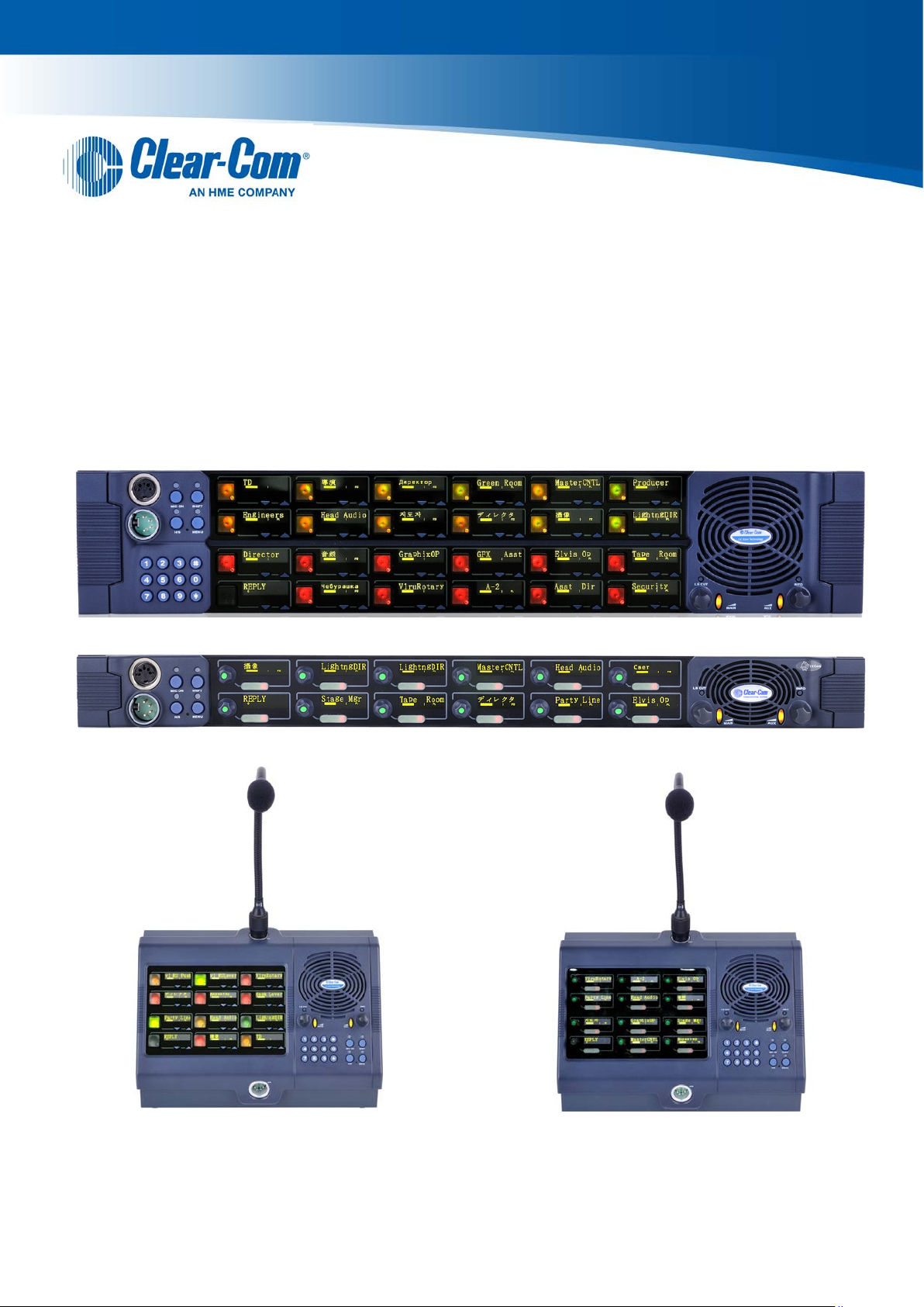
V-Series Panels
User Guide
PN: 399G057 Rev: A 08/22/13
C
Page 2

Document Reference
V-Series Panels User Guide
Part Number: 399G057 Revision: A
Legal Disclaimers
Copyright © 2013 HME Clear-Com Ltd.
All rights reserved.
Clear-Com, the Clear-Com logo, and Clear-Com Concert are trademarks or registered trademarks of
HM Electronics, Inc.
The software described in this document is f urnished under a license agreement and may be used
only in accordance with the terms of the agreement.
The product described in this document is distributed under licenses restricting its use, copying,
distribution, and decompilation/reverse e ngineering. No part of this document may be reproduced in
any form by any means without prior written authorizat ion of Clear-Com, an HME Company.
Clear-Com Offices are located in California, USA; Cambridge, UK; Montreal , Canada; and Beijing,
China. Specific addresses and contact informati on can be found on Clear-Com’s corporate website:
www.clearcom.com
Clear-Com Contacts
Americas and Asia-Pacific Headquarters
California, United States
Tel: +1.510.337.6600
Email: CustomerServicesUS@clearcom.com
Europe, Middle East, and Africa Headquarters
Cambridge, United Kingdom
Tel: +44 1223 815000
Email:
Canada Office
Quebec, Canada
Tel: +1 (450) 653-9669
China Office
Beijing Representative Office
Beijing, P.R.China
Tel: +8610 65811360/65815577
SalesSupportEMEA@clearcom.com
2
V-Series Panels User Guide
Page 3

Contents
1 Important Safety Instructions ........................................................................... 9
Safety symbols .................................................................................................................................. 10
Mains power cord .............................................................................................................................. 10
2 Introduction ...................................................................................................... 11
2.1 V-Series Panels covered by this guide ................................................................................. 11
2.2 Further information ................................................................................................................ 12
3 Overview ........................................................................................................... 13
3.1 Headset connector options ................................................................................................... 13
3.2 Expansion panel options ....................................................................................................... 13
3.3 Front panel lights and controls .............................................................................................. 14
3.3.1 V12LD ........................................................................................................................... 14
3.3.2 V12PD ........................................................................................................................... 14
3.3.3 V12RD ........................................................................................................................... 15
3.3.4 V24LD ........................................................................................................................... 15
3.3.5 V24PD ........................................................................................................................... 16
3.3.6 V24RD ........................................................................................................................... 16
3.3.7 V12LDE ......................................................................................................................... 17
3.3.8 V12PDE ......................................................................................................................... 17
3.3.9 V12RDE ........................................................................................................................ 17
3.3.10 V12LDD ......................................................................................................................... 18
3.3.11 V12PDD ........................................................................................................................ 19
3.3.12 V12RDD ........................................................................................................................ 20
3.4 Key display window ............................................................................................................... 21
3.4.1 Navigating the key display window ............................................................................... 22
3.4.2 Key display window controls ......................................................................................... 23
3.4.3 Navigating the Reply key display window ..................................................................... 25
3.5 Supported fonts in V-Series panels....................................................................................... 26
4 Using the Front Panel Controls ...................................................................... 27
4.1 Mic On ................................................................................................................................... 27
4.2 Shift Page .............................................................................................................................. 27
4.3 Headset Select ...................................................................................................................... 27
4.4 Menu ..................................................................................................................................... 28
4.5 LS Main levels (volume) control ............................................................................................ 28
3
V-Series Panels User Guide
Page 4

Auxiliary levels (volume) control ............................................................................................ 28
4.6
4.7 Listen Again ........................................................................................................................... 29
4.8 Up / Down buttons on lever key and pushbutton panels ...................................................... 29
4.9 Alternative text key ................................................................................................................ 29
4.10 Rotary control on rotary panels ............................................................................................. 30
4.11 Dial pad (2RU and desktop panels) ...................................................................................... 31
4.12 Push-To-Talk (PTT) operation .............................................................................................. 31
4.13 Status LEDs (Tallies) ............................................................................................................ 32
4.14 Communication errors ........................................................................................................... 33
4.15 Lever key panels ................................................................................................................... 33
4.15.1 Reply Key GPI functionality on lever key panels .......................................................... 33
4.16 Pushbutton panels ................................................................................................................ 33
4.16.1 Pushbutton Reply Key GPI Operation .......................................................................... 34
4.17 Rotary panels ........................................................................................................................ 34
4.17.1 Using rotary panel keys ................................................................................................. 35
4.17.2 Rotary panel Reply key ................................................................................................. 35
4.17.3 Assignment Panel (AP) mode and the INTERCOM key ............................................... 36
4.17.4 Rotary panel IFB operation ........................................................................................... 36
4.17.5 Rotary panel Forced Listen ........................................................................................... 37
4.17.6 Rotary panel Reply key GPI operation .......................................................................... 38
5 Using the Menu System .................................................................................. 40
5.1 Navigating the menu system ................................................................................................. 40
5.2 Fast Key Assign .................................................................................................................... 41
5.2.1 The Dial code ................................................................................................................ 42
5.2.2 Dial code validation ....................................................................................................... 42
5.3 Top level menu ...................................................................................................................... 44
5.4 SYS INFO (System Information) menu ................................................................................. 46
5.4.1 VIEW KEYS menu......................................................................................................... 47
5.4.2 PARTY LINE menu ....................................................................................................... 50
5.4.3 FIXED GRP menu ......................................................................................................... 52
5.4.4 NEAR PNLS menu ........................................................................................................ 53
5.4.5 MONITORS Menu ......................................................................................................... 54
5.4.6 FL SOURCE Menu ........................................................................................................ 55
5.4.7 FL DEST menu .............................................................................................................. 56
5.5 LOCAL PREF (Local Preferences) menu ............................................................................. 57
5.5.1 TIMEOUTS menu .......................................................................................................... 59
5.5.2 LEVEL ADJ (Level Adjust) Menu .................................................................................. 60
5.5.3 BRIGHTNESS menu ..................................................................................................... 63
4
V-Series Panels User Guide
Page 5

MESSAGE menu ........................................................................................................... 64
5.5.4
5.5.5 RESET XPTS (Reset Crosspoints) menu ..................................................................... 66
5.6 SYS CONFIG (System Configuration) menu ........................................................................ 66
5.6.1 PARTY LINE configuration menu .................................................................................. 68
5.6.2 FIXED GRP configuration menu ................................................................................... 70
5.6.3 LOCAL PNL (Local Panel) configuration menu ............................................................ 72
5.6.4 LOCAL KEYS configuration menu ................................................................................ 73
5.6.5 ATTRIBUTES menu ...................................................................................................... 76
5.6.6 REMOTE PNL menu ..................................................................................................... 77
5.6.7 FL CONFIG (Forced Listen configuration) menu .......................................................... 80
5.6.8 INPUT LVLS (Input Levels) configuration menu ........................................................... 82
5.6.9 OUTPUT LVL (Output Levels) configuration m enu ....................................................... 86
5.7 DIAGNOSTIC menu .............................................................................................................. 88
5.7.1 SYSTEM DATA menu ................................................................................................... 91
5.7.2 UPGRADE menu ........................................................................................................... 92
5.8 CALL menu ........................................................................................................................... 94
5.9 DIAL menu ............................................................................................................................ 96
5.10 LOCAL EXCL (Local Exclusive) menu .................................................................................. 98
5.11 LOCAL PAGE (Local Page override) menu .......................................................................... 99
5.12 ASSNMT PNL (Assignment Panel) menu ........................................................................... 100
5.12.1 Assigning IFB sources and destinations ..................................................................... 101
5.12.2 Assigning partyline members ...................................................................................... 103
5.12.3 Assigning Fixed Group members ................................................................................ 104
5.13 SUPERVISE menu .............................................................................................................. 105
5.14 SHIFT menu ........................................................................................................................ 109
5.15 Menu map ........................................................................................................................... 110
6 IP Configuration ............................................................................................. 111
6.1 Accessing the IP configuration menus ................................................................................ 111
6.2 IP SETUP menu .................................................................................................................. 112
6.2.1 CONNECT menu ......................................................................................................... 113
6.2.2 USER ID menu ............................................................................................................ 116
6.2.3 PASSWORD menu ..................................................................................................... 117
6.2.4 CNTL DELAY (Control Delay) menu ........................................................................... 118
6.3 NET SETUP menu .............................................................................................................. 120
6.3.1 IP ADDRESS menu..................................................................................................... 122
6.3.2 IP GATEWAY menu .................................................................................................... 123
6.3.3 DNS SERVER menu ................................................................................................... 124
6.3.4 MATRIX IP menu ........................................................................................................ 125
5
V-Series Panels User Guide
Page 6

LOGIN PORT menu .................................................................................................... 126
6.3.5
6.3.6 DHCP menu ................................................................................................................ 127
6.3.7 SUBNETMASK (Subnet Mask) menu ......................................................................... 127
6.3.8 CON TYPE (Connection Type) menu ......................................................................... 128
6.4 CONFIRM CLEAR menu .................................................................................................... 129
6.5 IP menu map ....................................................................................................................... 130
7 Installing V-Series panels ............................................................................. 131
7.1 Placing panels ..................................................................................................................... 131
7.1.1 Placing rack mounted panels ...................................................................................... 131
7.1.2 Placing desktop panels ............................................................................................... 131
7.1.3 Placing expansion panels ........................................................................................... 135
7.2 Wiring V-Series panels ........................................................................................................ 136
7.2.1 V-Series main panel rear connectors (no AES -3 or T-Adapter) ................................. 137
7.2.2 V-Series main panel rear connectors (AES-3) ............................................................ 137
7.2.3 V-Series main panel rear connectors (T-Adapter) ...................................................... 137
7.2.4 V Series expansion panel rear connectors ................................................................. 138
7.2.5 V-Series desktop panel rear connectors (no AES-3 or T-Adapter) ............................ 139
7.2.6 V-Series desktop panel rear connectors (AES-3) ....................................................... 139
7.2.7 V Series desktop panel rear connectors (T-Adapter) .................................................. 140
7.2.8 Mains power cord ........................................................................................................ 140
7.2.9 Power connector wiring ............................................................................................... 141
7.2.10 Analog matrix to panel wiring ...................................................................................... 141
7.2.11 Matrix panel GPIO connector wiring ........................................................................... 143
7.2.12 Programmable Relay contacts .................................................................................... 144
7.2.13 Opto-Isolated inputs .................................................................................................... 144
7.2.14 Auxiliary audio connector ............................................................................................ 146
7.2.15 AES-3 option to AES-6 interface card ......................................................................... 147
7.2.16 T-Adapter option to DIG-2/DIF-102 interface .............................................................. 149
7.2.17 LAN connector ............................................................................................................. 150
7.2.18 Expansion panel output ............................................................................................... 151
7.3 Front panel connectors ....................................................................................................... 152
7.3.1 Microphone connector ................................................................................................. 152
7.3.2 Headset connectors .................................................................................................... 153
7.4 Mains AC Power ................................................................................................................. 156
7.5 Panel parameters in ECS / EHX ......................................................................................... 156
7.5.1 Headset sidetone ........................................................................................................ 157
7.5.2 Headset autodetect ..................................................................................................... 157
7.5.3 Panel microphone gain ............................................................................................... 158
6
V-Series Panels User Guide
Page 7

Speaker dim ................................................................................................................ 158
7.5.4
7.5.5 Page Override ............................................................................................................. 159
7.6 Panel-to-matrix card baud rate ............................................................................................ 159
8 Maintaining V-Series panels ......................................................................... 160
8.1 Accessing the Local Maintenance Menu (LMM) ................................................................. 160
8.2 Navigating the LLM menu ................................................................................................... 161
8.2.1 Use of displays ............................................................................................................ 161
8.3 Commands .......................................................................................................................... 162
8.3.1 version ......................................................................................................................... 162
8.3.2 xpoint ........................................................................................................................... 163
8.3.3 level ............................................................................................................................. 165
8.3.4 control .......................................................................................................................... 166
8.3.5 limit .............................................................................................................................. 168
8.3.6 filter .............................................................................................................................. 169
8.3.7 la (Listen Again) .......................................................................................................... 171
8.3.8 mixer ............................................................................................................................ 172
8.3.9 setup ............................................................................................................................ 172
8.3.10 voicerec ....................................................................................................................... 173
8.3.11 voiceplay ..................................................................................................................... 174
8.3.12 intrim ............................................................................................................................ 174
8.3.13 outtrim ......................................................................................................................... 175
8.3.14 gpio .............................................................................................................................. 176
8.3.15 module ......................................................................................................................... 178
9 Specifications ................................................................................................ 179
9.1 Front panel controls and connectors ................................................................................... 179
9.2 Main panel rear connectors ................................................................................................. 179
9.3 AES-3 option rear connectors ............................................................................................. 179
9.4 T-Adapter option rear connector ......................................................................................... 180
9.5 Expansion panel rear connectors........................................................................................ 180
9.6 Panel microphone input ...................................................................................................... 180
9.7 Headset microphone input .................................................................................................. 180
9.8 Auxiliary loudspeaker output ............................................................................................... 180
9.9 Audio input/output ............................................................................................................... 181
9.10 AC mains power supply (external) ...................................................................................... 181
9.11 Temperature ........................................................................................................................ 181
9.12 Humidity .............................................................................................................................. 181
9.13 Dimensions (1RU panels) ................................................................................................... 182
9.14 Dimensions (2RU panels) ................................................................................................... 182
7
V-Series Panels User Guide
Page 8

Dimensions (Desktop panels) ............................................................................................. 182
9.15
10 Glossary ......................................................................................................... 183
8
V-Series Panels User Guide
Page 9

1 Important Safety Instructions
1. Read these instructions.
2. Keep these instructions.
3. Heed all warnings.
4. Follow all instructions.
5. Do not use this apparatus near water.
6. Clean only with dry cloth.
7. Do not block any ventilation openings. Install in acc ordance with the manufacturer’s
instructions.
8. Do not install near any heat sources such as radiators, heat registers, stoves, or other
apparatus (including amplifiers) that produce heat.
9. Do not defeat the safety purpose of the polarized or grounding-type plug. A polarized plug
has two blades and a third grounding prong. The wide blade or the third prong are provided
for your safety. If the provided plug does not fit int o your outl et, consult an electrician for
replacement of the obsolete outlet.
10. Protect the power cord from being walked on or pinched particularly at plugs, convenience
receptacles, and the point where they exit f rom the apparatus.
11. Only use attachments/accessories specified by the manufacturer.
12. Use only with the cart, stand, tripod, bracket, or table specified by the manufacturer, or s ol d
with the apparatus. When a cart is used, use caution when moving the cart/apparatus
combination to avoid injury from tip-over.
13. Unplug this apparatus during lightning storms or when unused for long periods of tim e.
14. Refer all servicing to qualified service personnel. Servicing is required when the apparat us
has been damaged in any way, such as power-cord supply or pl ug is damaged, liquid has
been spilled or objects have fallen into the apparatus, the apparatus has been exposed to rain
or moisture, does not operate normally, or has been dropped.
15. Warning: To reduce the risk of fire or electric shock, do not expose this product to rain or
moisture.
9
V-Series Panels User Guide
Page 10
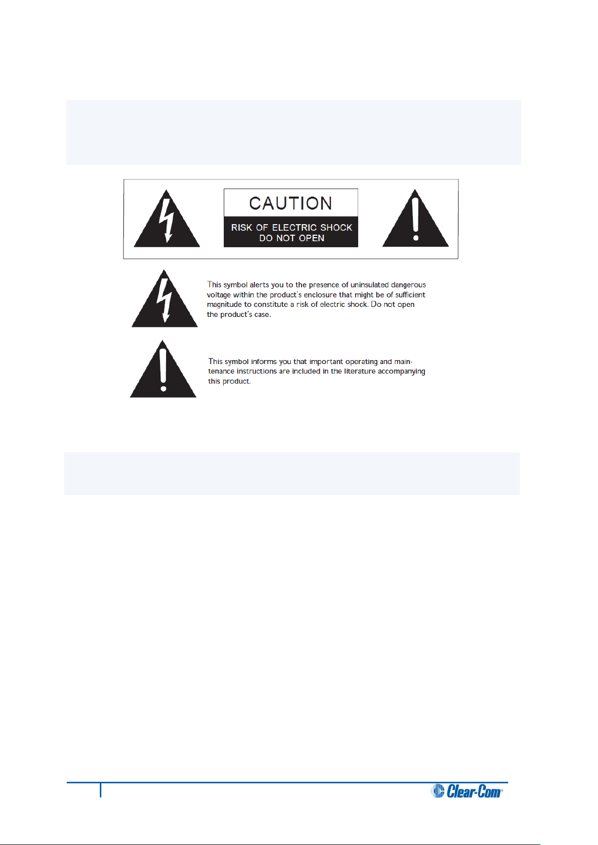
Safety symbols
Familiarize yourself with the safety symbols in Figure 1: Safety symbols. These symbols are
displayed on the apparatus and warn you of the potential danger of electric shock if the system is
used improperly. They also refer you to important operating and maintenance instructions in the
product user manual.
Figure 1: Safety symbols
Mains power cord
V-Series panels are powered by an external powe r s upply. The cord to connect the external power
supply to the mains supply must conform to t he following:
• The mains power cord shall have an IEC C13 connector at one end and a mains power plug
at the other end.
• An IEC C13 plug has three pins, the centre pin carrying the earth / ground. The other two
pins carry neutral and live circuits.
• The conductors of the mains cords shall have adequate cross-sectional area for rated current
consumption of the equipment.
• The mains plug that con nects to the mains supply must be approved for use i n the country
where the equipment is to be used.
• The mains power cord mu st be an IEC mains power cord complying with standard
IEC60320; IEC320/C13.
• Mains power cords use d i n the U.S. must also comply with standard UL817.
10
V-Series Panels User Guide
Page 11
Format
Product number
Description
19” rack mount 1RU 12 lever key panel.
V24LD
19” rack mount 2RU 24 lever key panel with dial pad.
Desktop 12 lever key panel.
19” rack mount 1RU 12 lever key expansion panel.
V12PD
V24PD
V12PDD
V12RDX4
V12RDX5
19” rack mount 2RU 24 rotary control panel with dial pad
(XLR4).
19” rack mount 2RU 24 rotary control panel with dial pad
(XLR5).
2 Introduction
This guide describes how to install, use and maintain V-Series™ user panel s from Clear-Com®
V-Series user panels are fully compatible with bot h the Eclipse and Eclipse HX digital matrix
systems, and are available in 12-key and 24-key pushbutton, rotary and lever key format s.
The panels incorporate a wide range of advanced features to enhance usability and audio
performance, including:
• Advanced Digital Si gnal Processing.
• 10-character displays.
• Listen Again memory.
• Clear-Com IP technology.
2.1 V-Series Panels covered by this guide
The V-Series family of panels comprises:
Lever Key V12LD
V12LDD
V12LDE
Pushbutton
19” rack mount 1RU 12 pushbutton panel.
19” rack mount 2RU 24 pushbutton panel with dial pad.
Desktop 12 pushbutton panel.
V12PDE
Rotary
19” rack mount 1RU 12 pushbutton expansion panel.
19” rack mount 1RU 12 rotary control panel (XLR4).
19” rack mount 1RU 12 rotary control panel (XLR5).
V24RDX4
V24RDX5
V12RDDX4
V12RDDX45
V12RDEY
11
V-Series Panels User Guide
Desktop 12 rotary control panel (XLR4).
Desktop 12 rotary control panel (XLR5).
19” rack mount 1RU 12 rotary control extension panel.
Table 1: V-Series Panels covered by this guide
Page 12

2.2 Further information
V-Series documentation is available from your pro duct CD-ROM. For more information about the VSeries family of panels, see:
http://www.clearcom.com/product/digital-matrix/user-panel
For more information about the Eclipse and Eclipse HX digital matrix systems, referenced by this
guide, see:
http://www.clearcom.com/product/digital-matrix
For sales information, see your Clear-Com sale s r epresentative. For contact information and legal
disclaimers, see Page 2 of this guide.
.
12
V-Series Panels User Guide
Page 13
Panel
Expansion panel support
V12LD
V24LD
V12PD
V24PD
V12RD
V24RD
V12LDD
V12PDD
V12RDD
3 Overview
This chapter provides an overview of the V-Series family of panel s, including:
• Headset connector and expansion panel options.
• Front panel lights an d controls.
• Key display and fonts.
Tip: For a brief description of all the V-Series panel s covered by this guide, including product
numbers, see
3.1 Headset connector options
The following headset connector options (one connector only) are available to V-Series panels:
Table 1: V-Series Panels covered by this guide.
• XLR-4M locking headset c onnection.
• XLR-5F headset connection.
• XLR-7M headset connecti on.
3.2 Expansion panel options
Up to eight V12LDE expansion panels in a daisy chain .
Up to eight V12PDE expansion panels in a daisy chain.
Up to eight V12RDE expansion panels in a daisy chain.
Do not support expansion panels.
Note:
Expansion panel types (lever key, pushbutton or rotary control) may not be mixed in a daisy chain of
such panels and must be connected to a main panel of the sam e t ype.
13
V-Series Panels User Guide
Table 2: Expansion panel options
Page 14
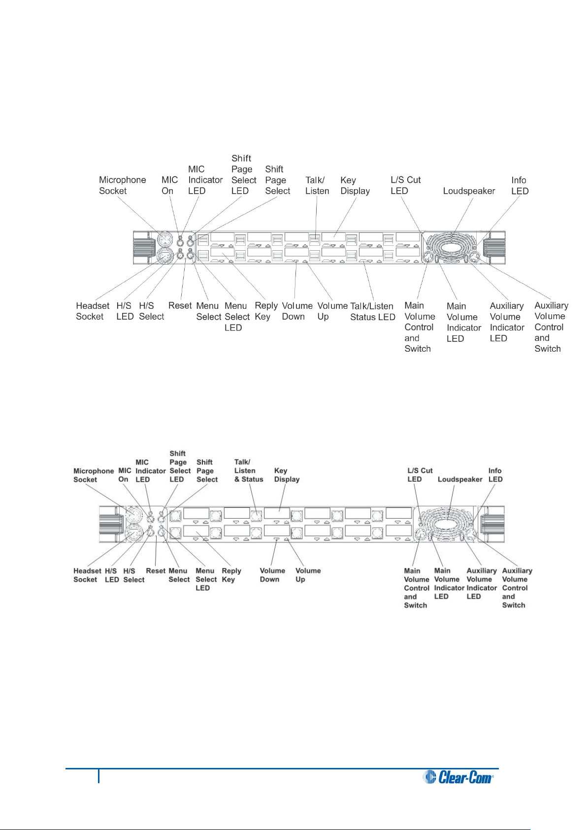
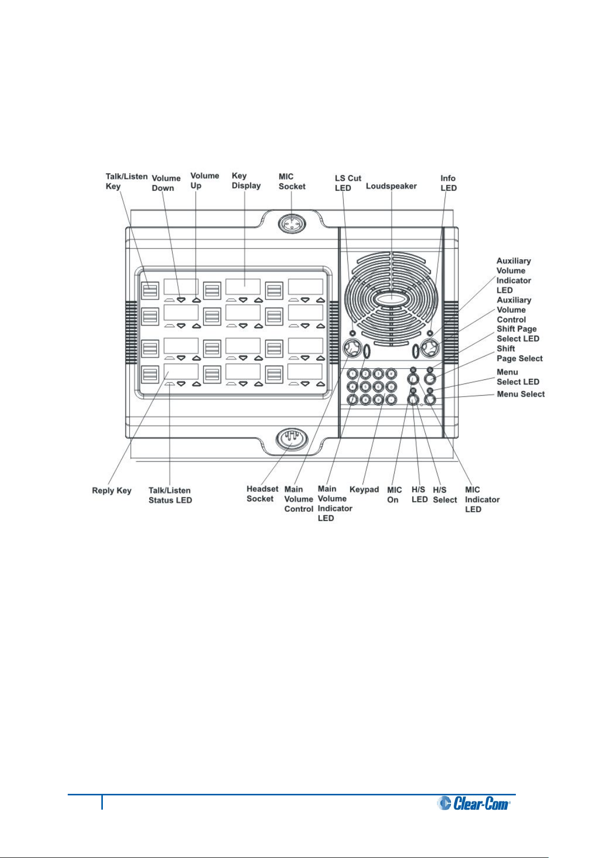
3.3 Front panel lights and controls
3.3.1 V12LD
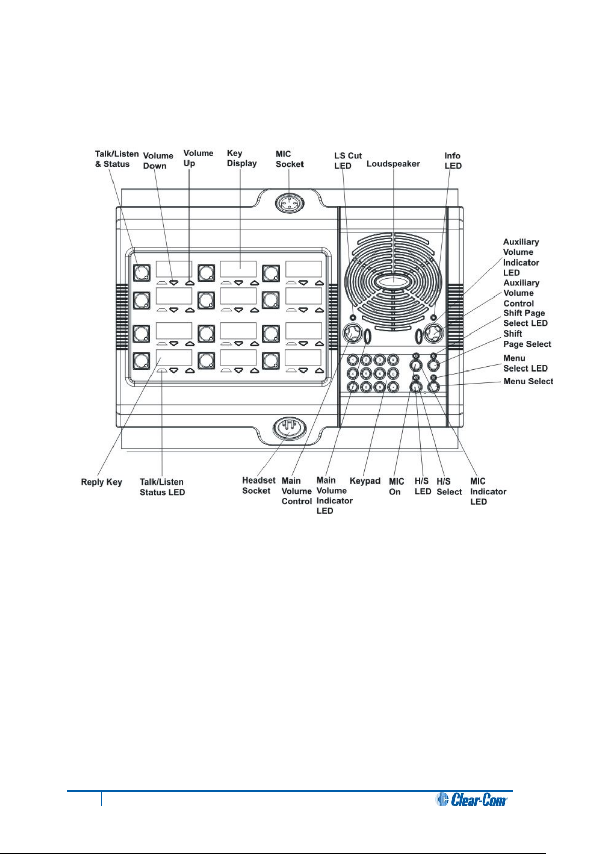
3.3.2 V12PD
Figure 2: V12LD front panel lights and controls
Figure 3: V12PD front panel lights and controls
14
V-Series Panels User Guide
Page 15
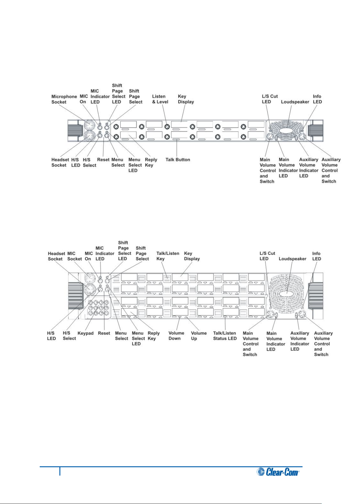
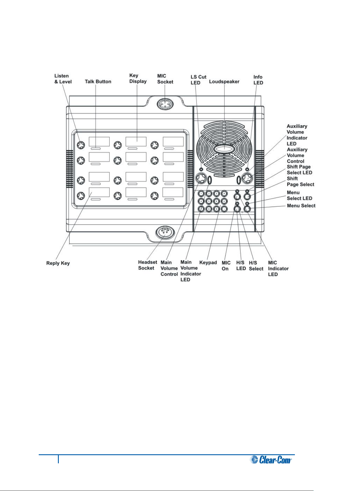
3.3.3 V12RD
3.3.4 V24LD
Figure 4: V12RD front panel lights and controls
15
V-Series Panels User Guide
Figure 5: V24LD front panel lights and controls
Page 16
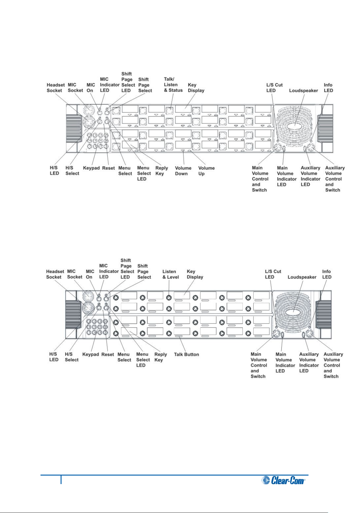
3.3.5 V24PD
3.3.6 V24RD
Figure 6: V24PD front panel lights and controls
16
V-Series Panels User Guide
Figure 7: V24RD front panel lights and controls
Page 17
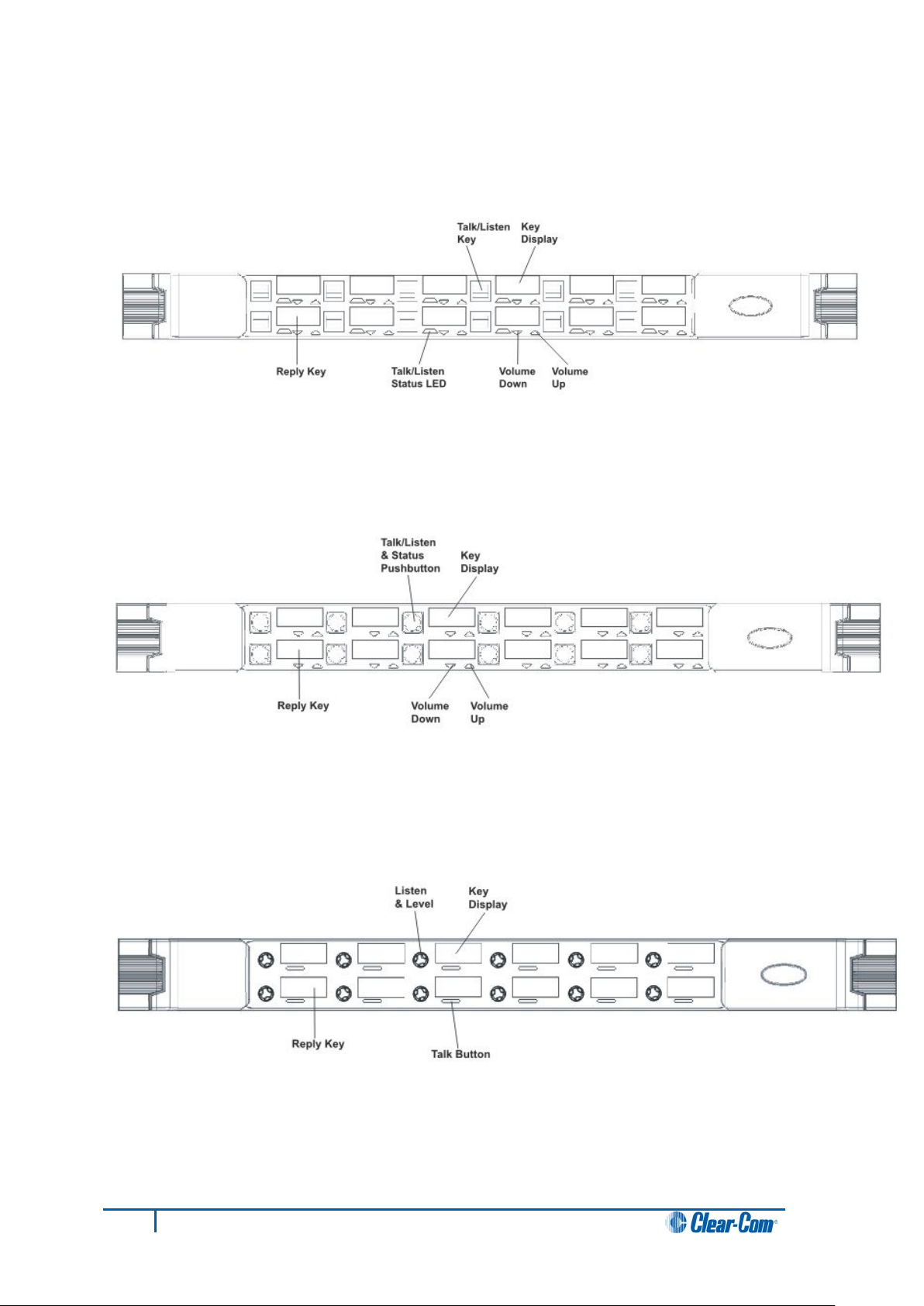
3.3.7 V12LDE
3.3.8 V12PDE
3.3.9 V12RDE
Figure 8: V12LDE front panel lights and controls
Figure 9: V12PDE front panel lights and controls
17
Figure 10: V12RDE front panel lights and controls
V-Series Panels User Guide
Page 18
3.3.10 V12LDD
18
V-Series Panels User Guide
Figure 11: V12LDD front panel lights and controls
Page 19
3.3.11 V12PDD
19
V-Series Panels User Guide
Figure 12: V12PDD front panel lights and controls
Page 20
3.3.12 V12RDD
Figure 13: V12RDD front panel lights and controls
20
V-Series Panels User Guide
Page 21

3.4 Key display window
The key display window is located next to the selection pushbutton, lever key or rotary
control.
You can access assigned labels either by pushing the selection control (pushbutton and
rotary panels) or toggling (lever key panels). Each key display window can be assigned as
many as nine labels, one each from the main page and the eight shift pages. A label may
either:
• Represent a talk or listen path to a panel, interface card or module, fixed group,
or partyline.
• Activate a programmable control function.
The key display window can display up to ten Latin or Katakana characters, or five Kanji
characters, together with status indicators for the key. These status indicators are:
• Currently selected page.
• Latched talk indicator.
• Latched listen indicator.
• Panel monitoring indicator.
• Microphone indicator.
• Incoming VOX indicator.
• Antenna active indicator.
• Destination type indicator (for example, a partyline, IFB, or Fixed Group).
• Remote panel connection.
21
V-Series Panels User Guide
Page 22
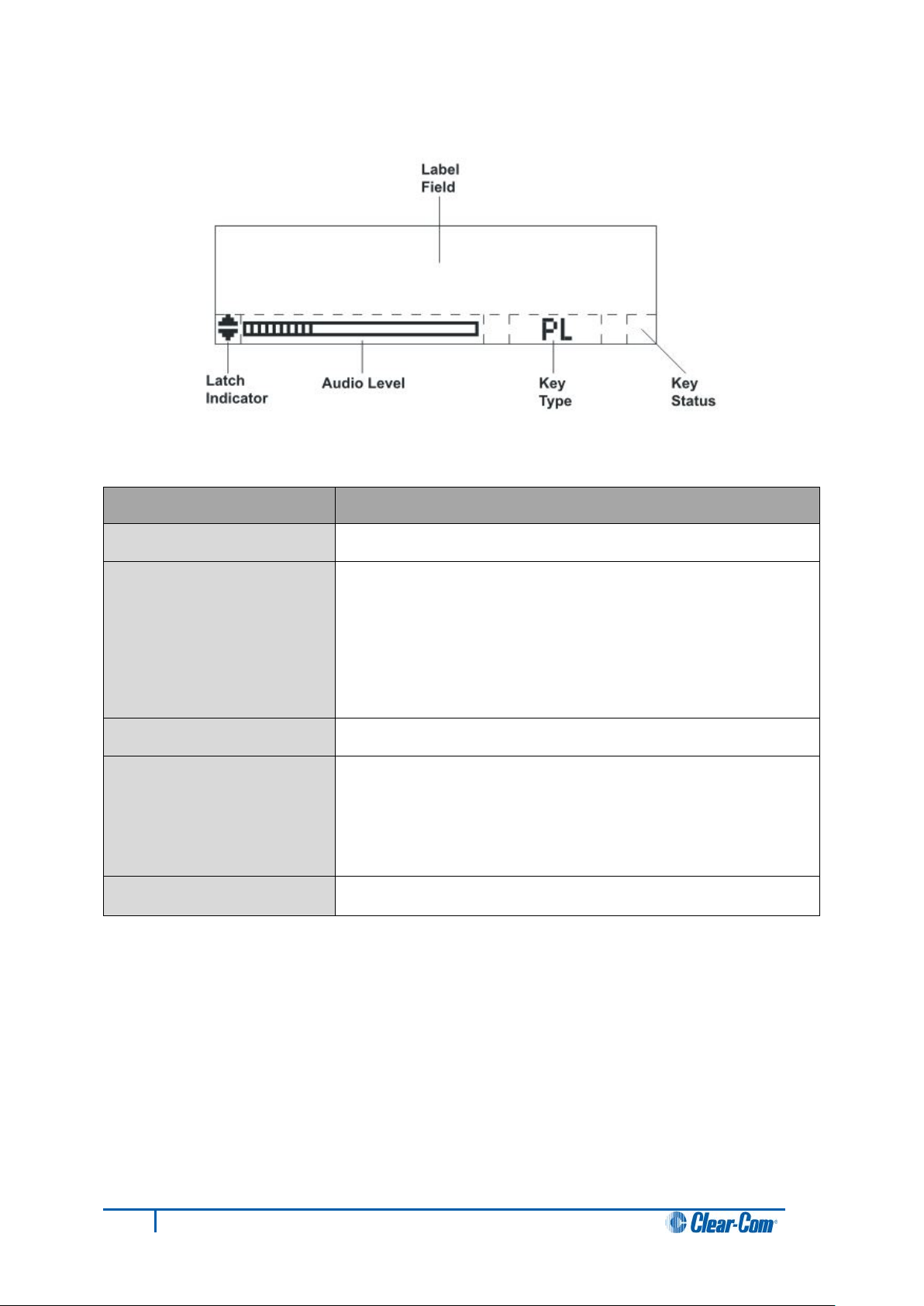
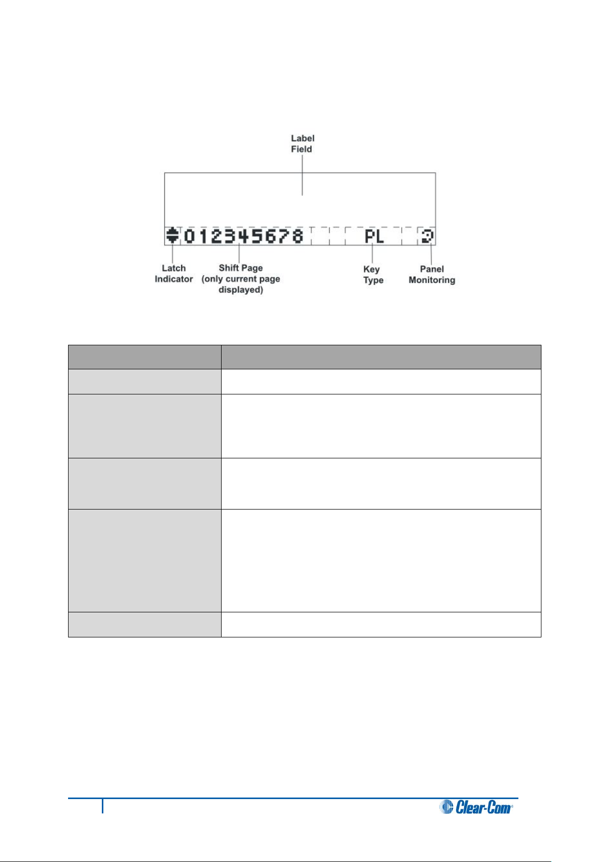
Feature
Description / comments
Label Field
10 character field for the key label.
Latch Indicator
Indicates the talk/listen status of the key.
Audio Level
A bar graph indicating the audio level set on that route.
Key Type
Indicates the type of route or action the panel key is
Key Status
Displays an icon indicating the status of this key
(see Figure 15: Key Status icons).
3.4.1 Navigating the key display window
Figure 14: Navigating the key display window
A down arrow indicates that the key is a latched talk key, an
up arrow indicates a latched listen key. Both arrows together
indicate a latched talk and listen key.
If no arrows are displayed the key is not latched.
connected to:
• PL = Party Line
• IFB = Interruptible Foldback
• FG = Fixed Group (includes stacked keys)
Table 3: Navigating the key display window
22
V-Series Panels User Guide
Page 23
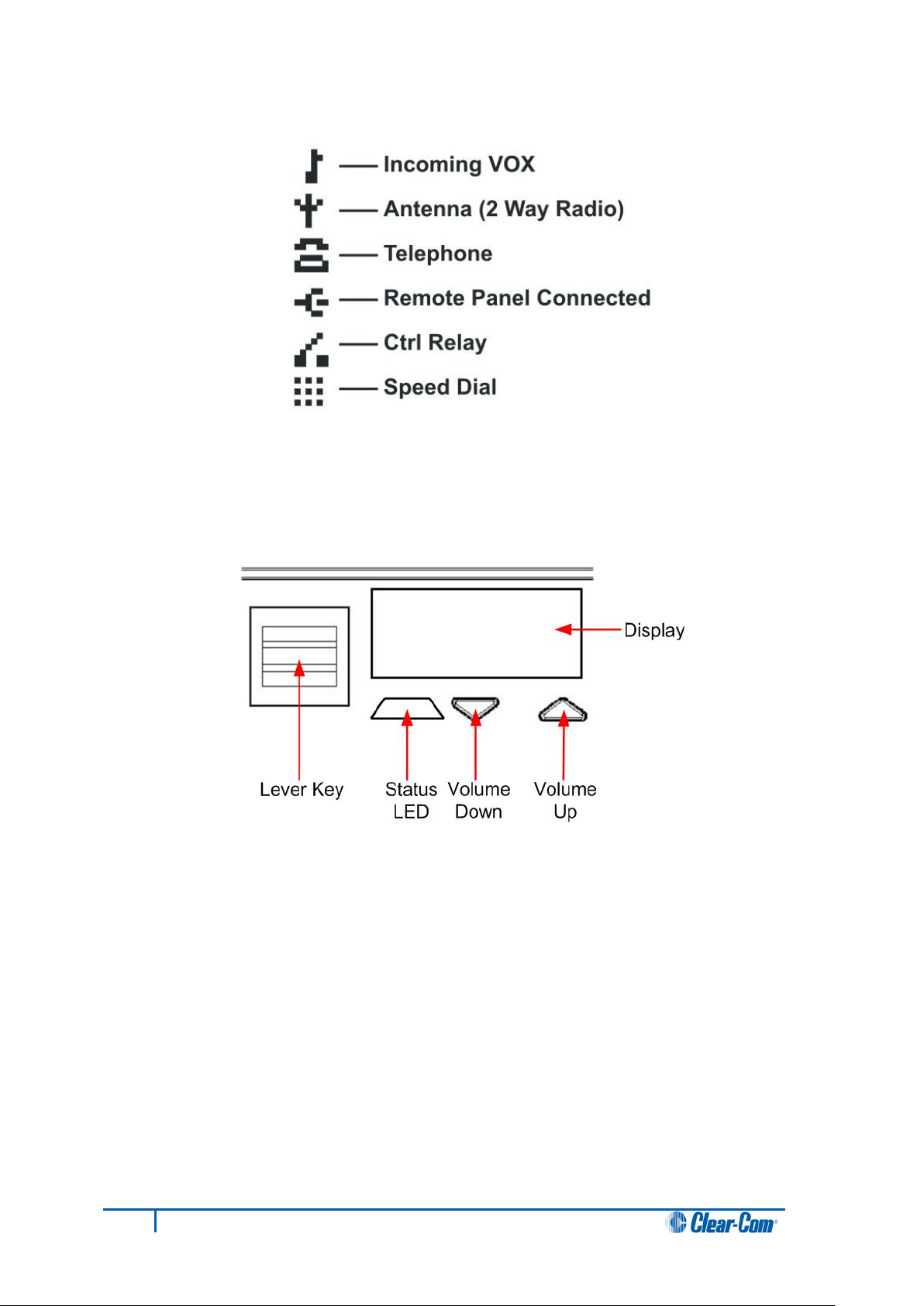
Figure 15: Key Status icons
3.4.2 Key display window controls
Figure 16: Lever key display window controls
23
V-Series Panels User Guide
Page 24
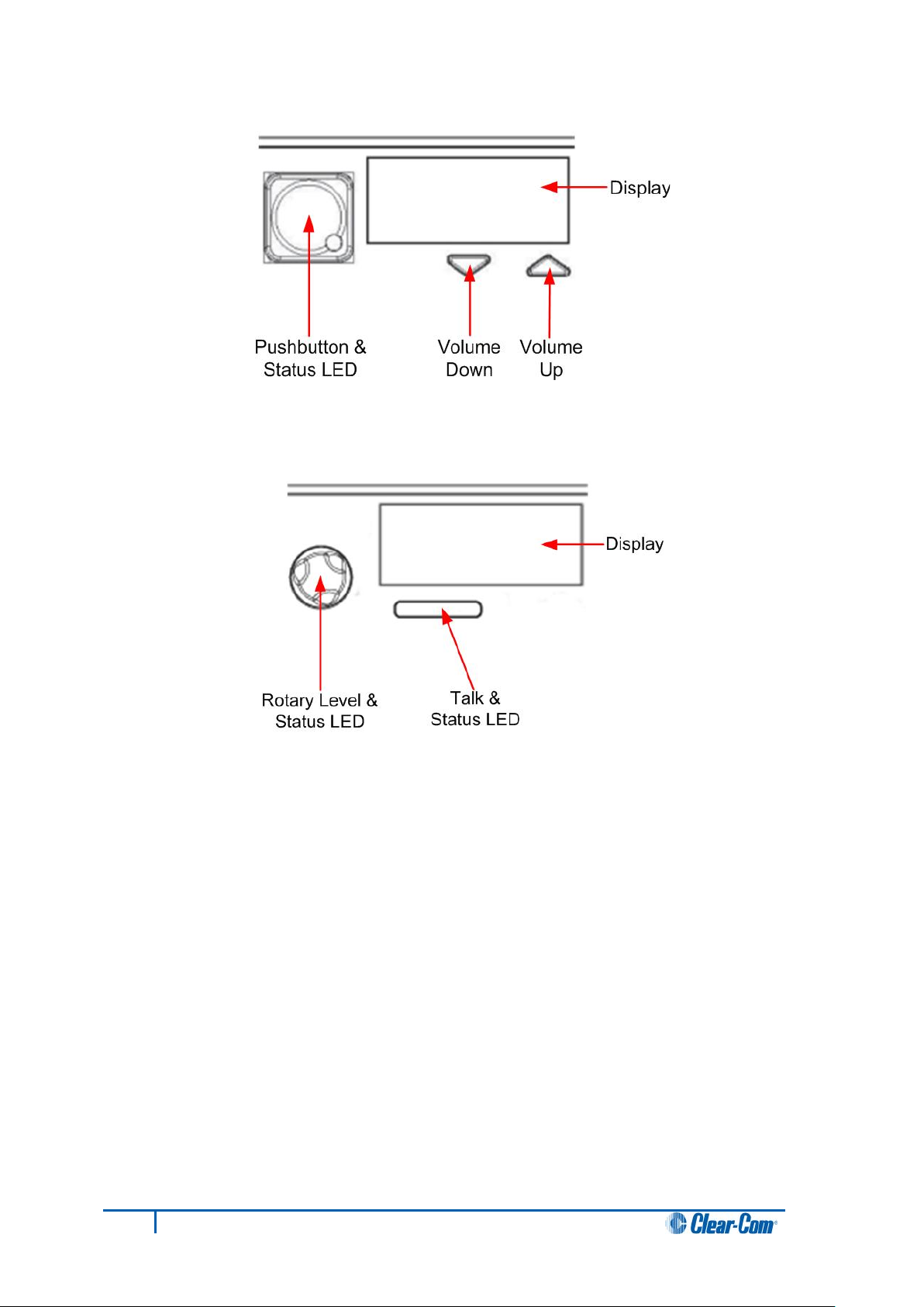
Figure 17: Pushbutton key display window controls
Figure 18: Rotary key display window controls
24
V-Series Panels User Guide
Page 25
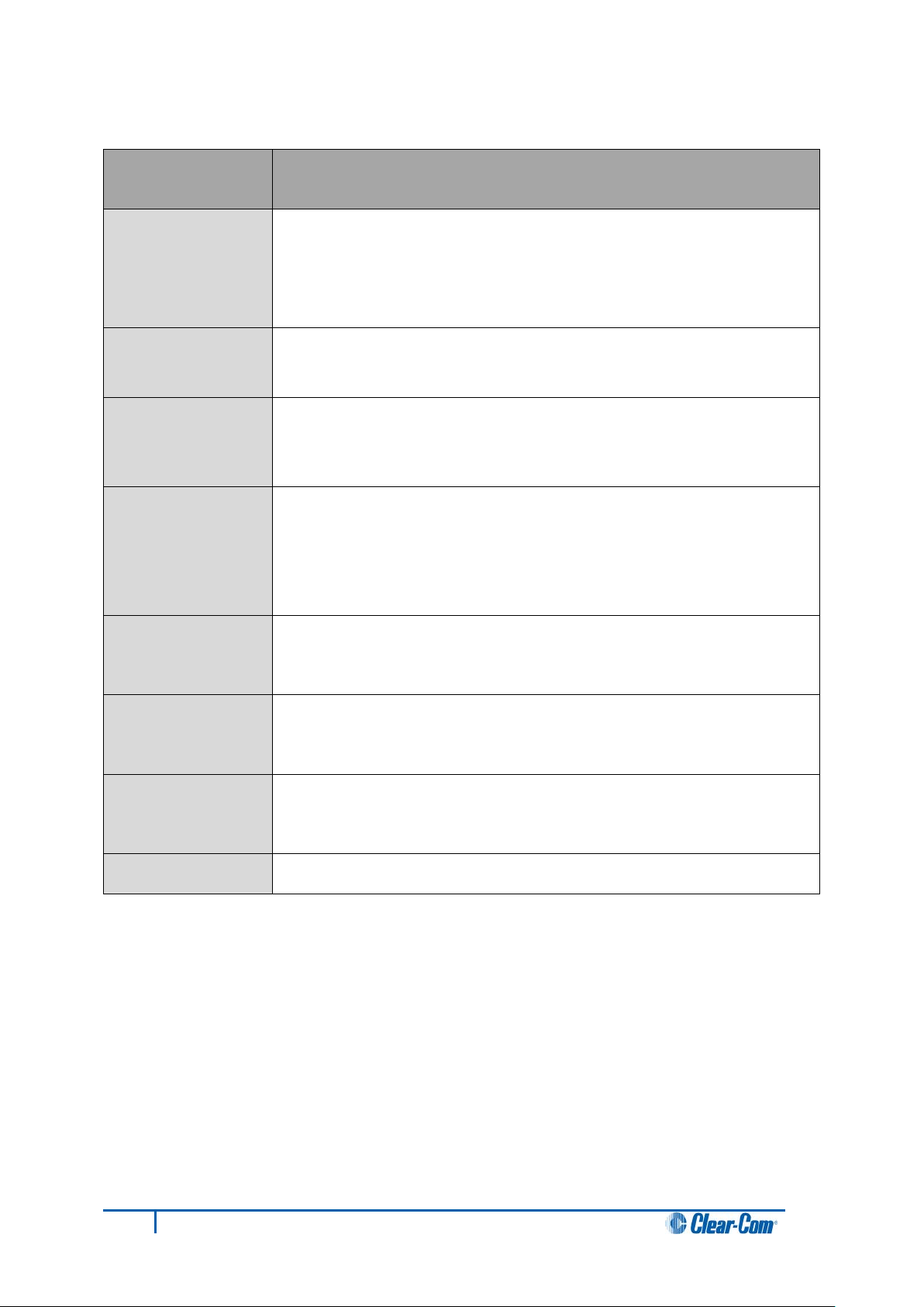
Feature
Description / comments
Label Field
10 character field for the Reply / caller label.
Latch Indicator
Indicates the latch status of the key.
Shift Page
The number of the current shift page. Only the current
Key Type
Indicates the type of route or action the Reply key is
Panel Monitoring
Displays an ear icon if the panel is being monitored.
3.4.3 Navigating the Reply key display window
Figure 19: Navigating the Reply key display window
As the Reply key is non-latching these indicators are not
displayed.
page number is displayed, with the digit in the position shown
in the illustration.
connected to.
When replying to an incoming call from a partyline, Fixed
Group or IFB the caller port is displayed rather than the
partyline, Fixed Group or IFB. The reply key only connects to
the caller.
Table 4: Navigating the Reply key display window
25
V-Series Panels User Guide
Page 26
The backslash is a Yen character. This is a size-maximized font (no
The V-Series panel display will support ten characters.
This is a normal, relatively-sized font. Covers Unicode 1024 to 1279
The V-Series panel display will support ten characters.
This covers the codepoint range 12352 to 12447 (decimal), 0x3040
The V-Series panel display will support five characters, as this is a
Displays 17,000 out of the 21,000 characters. This covers the
The V-Series panel display will support five characters.
The codepoint range is 65376 to 65440 (decimal), 0xFF60 to 0xFFA0
The V-Series panel display will support ten characters.
The character range supported on the VSeries panel is the Basic
Arabic character set 0x0600 to 0x06FF.
3.5 Supported fonts in V-Series panels
Font Description / comments
Basic Latin
Cyrillic
Hiragana
Full-width
Katakana
Kanji
descenders, lower-case characters are not relative in size to uppercase characters). This covers Unicode 32 to 127 (decimal), 0x20 to
0x7F (hex).
(decimal), 0x400 to 0x4FF (hex) with some missing characters.
to 0x309F (hex).
The V-Series panel display will support five characters.
normal width font.
This covers the codepoint range 12448 to 12543 (decimal), 0x30A0 to
0x30FF (hex) with some missing characters.
codepoint range 19968 to 40895 (decimal), 0x4E00 to 0x9FBF (hex).
Hangul
Half-width
Katakana
Arabic
The range is 44032 to 55215 (decimal), 0xAC00 to 0xD7AF (hex).
The V-Series panel display will support five characters.
(hex).
Table 5: Supported fonts
26
V-Series Panels User Guide
Page 27

4 Using the Front Panel Controls
This chapter describes the functionality of t he V-Series front panel controls in detail, including the
small functional differences between
panels.
Tip: For a brief description of all the V-Series panel s covered by this guide, including product
numbers, see
Table 1: V-Series Panels covered by this guide.
4.1 Mic On
The Mic On/Off button turns the currently selected microphone (gooseneck microphone or
headset microphone) on or off.
When the microphone is, on the red LED will come on to indicate that the microphone is
active. If a panel key is used to establish a talk connection the panel microphone is
automatically enabled and the indicator light is lit.
When the connection is terminated the microphone is automatically disabled.
lever key panels, pushbutton panels and rotary control
4.2 Shift Page
By momentarily pressing and releasing the Shift Page button, you can toggle between the
main page and the currently selected shift page.
When you press and hold the Shift Page button for more than 500ms, the panel is placed in
Shift Page mode. The Shift Page menu is shown on the display and the red indicator LED
is lit.
The software now supports named shift pages. This allows the user to give any shift page a
1 - 10 character name to better identify the use of the page. See EHX user guide for
information on the naming of shift pages.
4.3 Headset Select
The Headset Select button enables you to select the panel headset for audio output.
When you have selected a headset, the red LED indicator is lit. The panel microphone is
deselected, if active.
27
V-Series Panels User Guide
Page 28

4.4 Menu
V-Series panel functions are configured in Menu mode. You enter Menu mode by pressing
and releasing the Menu button.
When the panel enters Menu mode, the display windows are cleared of labels and the panel
menus are displayed. The blue menu LED is lit.
To exit an active menu, press the Menu button again.
Note:
Access to some panel menus can be disabled in ECS (Eclipse Configuration Software) /
EHX (Eclipse HX configuration software) through Advanced Settings > Menu Options in
Cards and Ports. A PIN code (set in the configuration software) must be entered to disable
access to these menus. When the PIN code is entered on the panel, access is granted. For
more information, see your ECS / EHX documentation.
4.5 LS Main levels (volume) control
The main levels (volume) control comprises a rotary encoder with push-switch action and
a tri-color loudspeaker volume indicator LED.
The LED volume indications are:
• Red - high volume.
• Amber - intermediate volume.
• Green - low volume.
Turn the volume control clockwise to increase the loudspeaker volume and anticlockwise to
decrease loudspeaker volume.
The loudspeaker cut indicator LED is lit red when the loudspeaker output is muted. Press
the volume control to toggle the loudspeaker cut.
4.6 Auxiliary levels (volume) control
The auxiliary panel levels (volume) control comprises a rotary encoder with push-switch
action and a tri-color loudspeaker volume indicator LED. The LED volume indications are:
• Red - high volume.
• Amber - intermediate volume.
• Green - low volume.
The auxiliary levels (volume) control sets the volume on the optional external loudspeaker
that you can connect to the auxiliary audio port on the rear of the panel. Turn the volume
control clockwise to increase the loudspeaker volume and anticlockwise to decrease
loudspeaker volume.
Press and release the auxiliary volume control to play back messages stored on the
Listen Again system (see next section).
28
V-Series Panels User Guide
Page 29

4.7 Listen Again
Note:
The Listen Again feature is configured in ECS / EHX. For more information, see your ECS /
EHX documentation.
Pressing the auxiliary volume control switch momentarily activates the
Listen Again feature. The last stored audio will be replayed (this feature
is configured in ECS / EHX).
Repeatedly pressing the auxiliary volume control will step back through the stored
messages.
4.8 Up / Down buttons on lever key and pushbutton panels
There is a pair of buttons to adjust the volume level on the connection beneath each key
display window on lever key and pushbutton panels (see
window controls
and Figure 17: Pushbutton key display window controls).
Use the left (Down) button to reduce the volume and the right (Up) button to increase the
volume.
You can also use the volume buttons to release a telephone line, in the same way as the
TEL RELEASE function in the diagnostic menu.
To release the telephone line, press both of the Up and Down buttons together.
The label display changes to TEL RELEAS, and the telephone is put back on the hook. All
latched keys on the local system are unlatched, killing all routes to the telephone. After
approximately 5 seconds, the display starts displaying the configured label again.
If the panel does not have Remote Line Release configured, then the call signal is sent to
the label instead.
Note:
The volume buttons are also used to adjust some settings that are accessed through the
panel menu, such as Sidetone Gain.
Figure 16: Lever key display
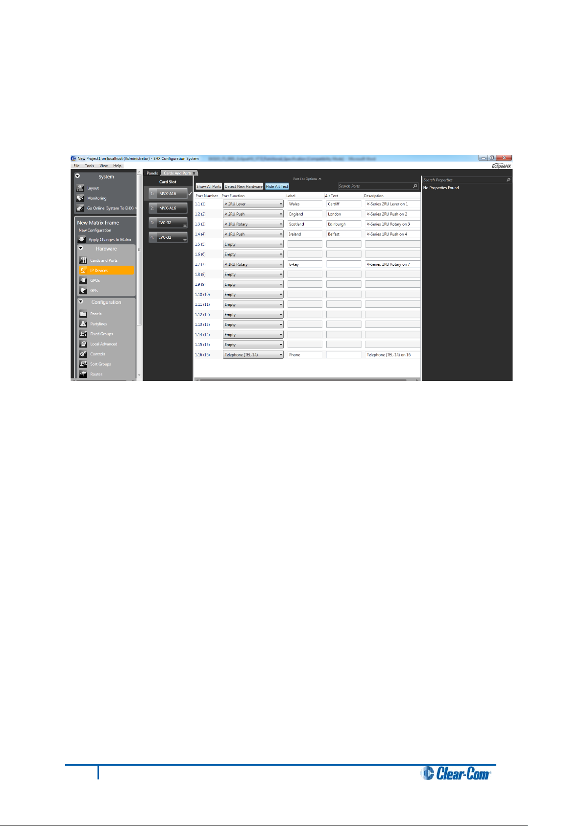
4.9 Alternative text key
Within the EHX software, you can define alternate text for display on a panel. You can then assign an
Alt Text key on the panel
When selected it will turn red, and inverse video and i f al t ernat e t ext is available for that label the
panel will show this.
Alias, VSM and PM text labels will override whichever state the panel is in.
One possible use of alternate text is to set up a dual language configuration on the panel, for example
to allow panels to display Arabic by default in a parti cular Middle Eastern broadcast installation.
English speakers could then select the Alt Text key on a panel to see the English equivalents to the
Arabic labels.
29
V-Series Panels User Guide
Page 30
Another use could be that both the role name and user name could be configured for each panel or
beltpack port. This would allow panel users to see either the name or the role depending on the Alt
Text mode selected.
You can enter alternate text on all the entity screens. The column with the text can be shown or
hidden from EHX using the button in the Port List opt i ons.
4.10 Rotary control on rotary panels
The rotary control located next to the key window display on rotary panels is used to adjust
the volume on the connection. Turn the rotary control clockwise to increase the volume and
anticlockwise to decrease the volume.
Holding the talk key and turning the rotary adjusts the IFB send level.
You can also use the rotary control to release a telephone line, in the same way as the TEL
RELEASE function in the diagnostic menu.
To release the telephone line, press and hold the rotary control.
The label display changes to TEL RELEAS, and the telephone is put back on the hook. All
latched keys on the local system are unlatched, killing all routes to the telephone. After
approximately 5 seconds, the display starts displaying the configured label again.
If the panel does not have Remote Line Release configured, then the call signal is sent to
the label instead.
Note:
The rotary control is also used to adjust some settings that are accessed through the panel
menu, such as Sidetone Gain, and scrolling through lists.
30
V-Series Panels User Guide
Page 31

Dial pad key
Menu shortcut
1
Dial menu
2
Local Exclusive
3
Local page override
4
Assignment Panel menu
5
Local Key Assign menu
7
Local Preferences menu
8
Fast Key Assign menu
9
Diagnostics menu
Option
Description / comments
No Function
The headset PTT does not activate any talk or
Activate All Talk Keys
The headset PTT activates the audio routes for all
Unlatched talk and listen keys are not activated.
Activate Two-Way Radio Talk Keys
The headset PTT activates the
audio routes on all latched talk keys attached to
4.11 Dial pad (2RU and desktop panels)
Use the dial pad on 2RU panels and desktop panels to:
• Access some menu pages directly (as a shortcut).
• Enter dialcodes, to dial out thru a telephone interface, such as the TEL-14 interface
module.
The menu shortcuts available from the dial pad are as follows:
Table 6: Dial pad menu shortcuts
When the dial pad keys are used to access a menu function, The blue menu LED is lit.
4.12 Push-To-Talk (PTT) operation
Push-To-Talk (PTT) operation on V-Series panels is performed using a PTT switch on either:
• The panel headset.
• The auxiliary audio connector on the rear of the panel.
The operation of PTT on the V-series panels is configured in Logic Input Options ECS /
EHX. You can set the Headset PTT Function to one of three options:
listen routes.
latched talk keys.
31
V-Series Panels User Guide
Page 32

two-way radios.
LED action / state
Description / comments
Solid red
A talk path (audio route) is active.
Solid green
A listen path (audio route) is active.
Solid amber
A talk and listen path (audio route) is active.
LED is off
LED flashing
LED is dim red
Key is configured as a talk key or a menu option is
selectable.
LED is dim green
LED is dim amber
selectable.
LED is blue
Menu mode is active.
Unlatched talk keys and listen keys are not
activated.
Table 7: Headset PTT options
4.13 Status LEDs (Tallies)
Status LEDs (tallies) indicate the status of a key, audio route, or menu option.
Note:
In the case of lever key panels, the status LEDs are set under the display windows. In
pushbutton panels, the push buttons themselves act as status indicators, and there are no
separate LEDs. In rotary panels, the rotary controls and the talk buttons act as status
indicators.
The status LEDs (tallies) signal the following:
Key is either not configured or the menu option is not
selectable.
Either user action is required, or there is an incoming call or
call signal.
Key is configured as a listen key or menu option is selectable
Key is configured as a talk and listen key or menu option is
Table 8: LED actions / states
Important note:
Specific information on the operation / action of status LEDs (tallies) is provided by sections
describing specific functionality and / or menu operations.
32
V-Series Panels User Guide
Page 33

4.14 Communication errors
If the panel loses data communication with the matrix, the following message is displayed:
Waiting for Eclipse
When data communication is restored, the panel automatically returns to normal operation.
4.15 Lever key panels
Lever keys can:
• Have both talk and listen labels assigned to the same key in ECS / EHX.
• Be used as either talk or listen keys, depending on whether the key is moved up or
down. If the key is moved upwards then the listen function is selected while if the key
is moved down then the talk function is selected.
The lever keys normally default to latching unless the non-latching option is configured in
ECS / EHX under Global Settings (Latch Disable set to True) for the destination port. In
the default state (latching), pressing the lever key momentarily up or down latches the key.
If you hold the lever key in the talk or listen position for more than 200ms, the lever key does
not latch and the connection terminates as soon as the key is released.
When the key is inactive, the talk/listen status indicator below the key is lit amber. When a
talk path is active (key pressed down) the status light is lit red, and when a listen path is
active (key pressed up) the status light is lit green.
An incoming call to the panel will cause the Reply key indicator to flash red. To take the call,
press the reply key down. To clear the call press the Reply key up.
4.15.1 Reply Key GPI functionality on lever key panels
If you connect a footswitch (or other type of switch) to GPI 3, which is preassigned to the
Reply key, the panel clears the item that is currently being viewed on the reply stack when
you release the switch.
You can use the Reply key up/down to scroll through the Reply key stack if more than one
call is present on the answerback stack. To move to the next call, press the up button. To
return to the previous call, press the down button.
For more information, see [Opto-Isolated Inputs] and your ECS / EHX documentation.
4.16 Pushbutton panels
Pushbuttons are either talk or listen keys, according to how they have been assigned in
ECS / EHX.
Pushbuttons normally default to latching unless the non-latching option is configured in
ECS / EHX under Global Settings (Latch Disable set to True) for the destination port. In
the default state (latching), pressing the button momentarily latches the key.
33
V-Series Panels User Guide
Page 34

If you hold the pushbutton for more than 200ms, the lever key does not latch and the
connection terminates as soon as the key is released.
When the pushbutton is inactive, the pushbutton is lit either dim red, green or amber
(depending on whether it is configured as a talk (red), listen (green) key, or talk and listen
(amber) key.
When the pushbutton is active, the pushbutton is lit either bright red, green, or amber,
according to how it is assigned.
To cancel a connection, press the pushbutton. The button returns to dim illumination.
An incoming call is signalled by a flashing red Reply pushbutton. To pick up the call, press
the Reply pushbutton.
4.16.1 Pushbutton Reply Key GPI Operati on
Connecting a footswitch (or other type of switch) to GPI 3, which is preassigned to the Reply
key, the panel will not clear the item that is currently being viewed on the reply stack when
you release the switch.
You can use the Reply key up/down to scroll through the Reply key stack if more than one
call is present on the answerback stack. To move to the next call, press the up button. To
return to the previous call, press the down button.
For more details, see [Opto-Isolated Inputs] and your ECS / EHX documentation.
Tip: For an audio block diagram for V-Series panels, see [figure cross-ref].The diagram
shows all the allowed audio routes and valid crosspoints allowed by V-Series panels. Some
of the audio paths shown by the diagram are only available with the audio mixer function in
ECS / EHX.
4.17 Rotary panels
Rotary panels can have talk and listen labels assigned to the same key in ECS / EHX. The
talk and listen functions are divided between the rotary control (listen) and the pushbutton
under the display (talk).
If the rotary control is pressed then the listen function is selected. The rotary control light is lit
green.
If the pushbutton (talk button) under the display is pressed, then the talk function is selected
and the talk button is lit red.
If listen is latched while talking, then the rotary control is lit green and the pushbutton (talk
button) is lit red.
Figure 20: Rotary panel display: latched listen while t alking
34
V-Series Panels User Guide
Page 35

4.17.1 Using rotary panel keys
By default, the talk label is displayed on a key, unless a listen only label is configured for the
key.
In assignment panel mode, the talk labels are shown on possible IFB destinations and the
listen labels are shown when the user is selecting an IFB source.
The rotary control and talk button normally default to latching unless the non-latching option
is configured in ECS / EHX under Global Settings (Latch Disable set to True) for the
destination port.
In the default state (latching), pressing the rotary control or talk button momentarily latches
the key.
If you hold the rotary control or talk button for more than 200ms, the key does not latch and
the connection terminates as soon as the key is released.
When the rotary control is inactive, the center of the control is lit dim green. When the talk
button is inactive, the button is lit dim red.
If the brightness control is turned down further, the dimmed lighting of the rotary control and
talk button is turned off entirely.
When you press the rotary control to establish a listen route, the center of the control is lit
bright green. When you press a talk button to establish a talk route, the button is lit bright
red.
To cancel the connection press the rotary control or talk button.
.
An incoming call is signalled by a flashing red Reply key talk button. To pick up the call
press the reply key talk button.
4.17.2 Rotary panel Reply key
The Reply key on a rotary panel can be overwritten with other talk and listen labels in ECS /
EHX without being deleted. This enables the creation of:
• 12 listen and 12 talk pai rs for each 1RU panel.
• 24 listen and 24 talk pai rs for each 2RU panel.
If you enter Menu mode and the reply key has been overwritten / is no longer available, the
Assignment Panel (AP) functions are disabled. If the labels placed on the Reply key are
removed in ECS / EHX, the Reply key becomes available again and Assignment Panel
functions are restored.
You can use the Reply key rotary control to scroll through the Reply key stack if more than
one call is present on the answerback stack. To move to the next call, turn the rotary control
clockwise. To return to the previous call, turn the rotary control anticlockwise.
35
V-Series Panels User Guide
Page 36

4.17.3 Assignment Panel (AP) mode and the INTERCOM key
Assignment Panel (AP) mode is enabled in ECS / EHX. AP mode enables you to add
members to local partylines (conferences), local Fixed Groups, and route local audio
sources to Global IFBs.
There are three ways to access AP mode on rotary panels:
• Press Menu and then select ASSNMT PNL.
• Press the dial pad 4 key (a shortcut to the ASSNMT PNL menu).
• Press an assigned INTERCOM button.
You can assign a special INTERCOM button to any key on a rotary panel including the
Reply key in ECS / EHX. The position of the INTERCOM key on the panel determines which
buttons are available for making assignments and which remain in intercom mode. This
feature extends to expansion panels, enabling you to perform intercom and assignment
operations simultaneously.
When the INTERCOM key is selected, the panel enters Assignment Panel (AP) mode
without
entering Menu mode. If you select a INTERCOM key that has been placed on an expansion
panel, then the expansion panel (and any other expansion panels in the daisy chain) is
placed in AP mode and can be used normally.
You use the INTERCOM key in exactly the same way as the Reply key in Menu mode when
making assignments.
For detailed information about making assignments, and the appearance of the panel
displays, see 5.12
For more information about using the dial pad to perform tasks, see
4.11
Dial pad (2RU and desktop panels)
Note:
If the Reply key has not been reassigned in ECS / EHX, the talk button on the Reply key will
also flash when in AP mode, mimicking the INTERCOM key status.
ASSNMT PNL (Assignment Panel) menu.
4.17.4 Rotary panel IFB operation
When a rotary panel key is assigned as an IFB source, you can use the rotary control to
adjust the audio level sent from the panel to the destination or the listen level at the panel.
If you latch the call to the IFB destination by momentarily pressing the talk button, you can
adjust the level of the audio sent to the IFB destination by turning the rotary control.
If the call to the IFB destination is not latched (the talk button is held down) the audio level is
adjusted by pressing and turning the rotary control.
36
V-Series Panels User Guide
Page 37

Figure 21: Rotary Panel latched and unlatched talk to IFB
4.17.5 Rotary panel Forced Listen
Forced listen key operation on rotary panels differs from lever key and pushbutton panels. A
forced listen key on a rotary panel will show the rotary control lit bright green to indicate
active listen.
Pressing the rotary control, when it is configured as a forced listen, will mute the audio from
the forced listen. Pressing the rotary encoder again restores the forced listen audio.
37
V-Series Panels User Guide
Page 38

4.17.6 Rotary panel Reply key GPI operation
Connecting a footswitch (or other type of switch) to GPI 3, which is preassigned to the Reply
key, the panel will not clear the item that is currently being viewed on the reply stack when
you release the switch.
For more details, see gOpto-Isolated Inputs and your ECS / EHX documentation.
Tip: For an audio block diagram for V-Series panels, see [figure cross-ref].The diagram
shows all the allowed audio routes and valid crosspoints allowed by V-Series panels. Some
of the audio paths shown by the diagram are only available with the audio mixer function in
ECS / EHX.
38
V-Series Panels User Guide
Page 39

Figure 22: V-Series audio block diagram
39
V-Series Panels User Guide
Page 40

5 Using the M e nu System
This chapter describes the structure and functionality of the V-Series menu system.
Tip: For a brief description of all the V-Series panel s covered by this guide, including product
numbers, see
5.1 Navigating the menu system
To enter menu mode, press the menu button on the front panel to display the top level
menu.
The menu LED will light and various menu options are displayed on the key displays.
Table 1: V-Series Panels covered by this guide.
Note:
Access to the System Configuration, Local Preferences and Diagnostic menus is set
from ECS / EHX. Depending on the configuration, access to some or all of these menus may
be disabled on the panel.
To navigate each menu level:
• On lever key or pushbutton panels, use the lever keys or pushbuttons associated
with a particular menu option to select that option.
Note:
Press lever keys down (Talk) to select menu options. The up (Listen) direction is not
active except in the case of the View Keys and Local Keys menus, where you can
use both up and down (Talk and Listen) key presses to select menu options.
• On rotary panels, use the talk button associated with the displayed menu option to
select that option.
The selected menu options are then displayed on the panel and the process is repeated until
you reach the setting you want to enable, disable or adjust.
To return to the previous menu use the Reply key talk button (which displays the name of
the current menu).
40
V-Series Panels User Guide
Page 41

To scroll through label lists:
• On lever key and pushbutton panels, use the up/down volume control buttons.
• On rotary panels, use the rotary control.
Note:
You can access the following menus directly using the dial pad on the 2RU and desktop
panels:
1 - Dial menu
2 - Local Exclusive
3 - Local page override
4 - Assignment Panel menu
5 - Local Key Assign menu
7- Local Preferences menu
# - Fast Key Assign
For more information, see 4.10
Dial pad (2RU and desktop panels).
5.2 Fast Key Assign
The Fast Key Assign facility on V-Series panels with dial pads enables you to create and
delete local key assignments through the dial pad (see 4.10
panels)
).
This facility is enabled in ECS / EHX in Advanced Settings (see your ECS / EHX
documentation).
To enter Fast Key Assign mode on a panel press the # key on the dial pad. The Reply key
displays FAST ASSN in inverted text.
Figure 23: Fast Key Assign for rack mount panels
Dial pad (2RU and desktop
41
V-Series Panels User Guide
Page 42

Figure 24: Fast Key Assign for desktop panels
5.2.1 The Dial code
The fast key assign requires 3 to 5 key presses for a dial code number to use. The dial code
number will be displayed on the reply key as the user is dialling it. The first port number dial
code will be 1 and all entity types will be 1 indexed.
5.2.2 Dial code validation
To terminate a Dial Code number the user must press the * key. At this point the Dial Code
number is verified to see if the user is allowed to assign the entity to the panel through the
sort group rules. If it is an invalid or disallowed operation then “Invalid” will be displayed on
the reply key. If it is valid, then the label for the entity will be displayed on the reply key and
the key labels which it can be assigned to will flash. The rack will determine if the entity is
assignable by looking in the entity table to see if the “Protect Port from Assignment” bit has
been set and if the talk and listen bits are cleared. Also the Sort groups will be checked to
see if the user panel is allowed to assign the entity.
Whether the key assigned has its talk or listen bits set will be determined by the default
settings on the port set in ECS. Note if the talk and listen bits are set, a Talk + Listen key will
be configured not a Talk + Forced Listen. On a lever or rotary V-Series panel the talk will be
placed on the talk key and the listen on the listen key. The rotary encoder panel will also
support talk forced listen. The force listen will be assigned to the encoder key and the talk to
the push button key.
Sort groups
If the destination is a member of a valid local sort group, you can scroll the members of the
sort group until you reach the desired destination by using the up/down buttons or rotary
controller on the Reply key. Any member of the sort group may be selected for assignment.
Note:
If the destination port is a member of a sort group that is blocked for the panel the word
BLOCKED is displayed in the reply key. Sort group permissions are set in ECS / EHX. For
more information, see your ECS / EHX documentation.
42
V-Series Panels User Guide
Page 43

Assigning keys
Select one of the flashing keys by pressing one of the following:
• The pushbutton on pushbutton panels.
• The key down on lever key panels.
• The talk button on rotary panels.
The selected destination port will be assigned to that key. When a key has been assigned,
the talk/listen attributes are defined in ECS / EHX. You can change the assigned key
attributes later from the local panel menu.
To exit assign mode press Menu on the panel.
43
Figure 25: Fast Key Assign sequence
V-Series Panels User Guide
Page 44

Deleting key assignments
To delete a key assignment, press the # key followed by the * key. The Reply key displays
DELETE? and all the keys that can be deleted flash.
To delete the assignments on one of the flashing keys, press:
• The associated pushbutton (pushbutton panels).
• The associated key down (lever key panels).
• The associated talk button (rotary panels).
To exit delete mode press the Menu button.
5.3 Top level menu
To enter the menu system press the Menu button on the front panel. The top level menu is
displayed and the blue menu LED is lit.
Press Menu again to exit Menu mode.
Figure 26: Main menu display for rack mounted panels
Figure 27: Main menu display for desktop panels
44
V-Series Panels User Guide
Page 45

Menu option
Description / comments
The main menu options are as follows:
SYS INFO
LOCAL PREF
SYS CONFIG
DIAL
LOCAL EXCL
ASSNMT PNL
Comprises menu options that enable panel keys and nearby
panels to be viewed.
Comprises menu options that enable you to configure
preferences on the panel, such as brightness levels, timeouts
and audio levels.
Comprises menu options that enable local panel configuration,
input levels adjustment and output levels adjustment.
Enables manual dialing on panel types without a dial pad.
Used to temporarily deactivate latched keys during talk or listen.
Requires the matrix to be online.
Comprises menu options that enable keys to be assigned locally
to IFBs, partylines and Fixed Groups.
MESSAGE
CALL
DIAGNOSTIC
LOCAL PAGE
SUPERVISE
Used to record and review an outgoing audio message.
Used to place labels on the reply stack, creating a temporary
user key.
Provides access to the diagnostic menu options, where you can
view system information, reset the panel and test audio links.
Enables the user to override the destination volume settings,
and talk to the connected panels.
Places the panel in Supervisor mode, enabling you to
supervise (take control of) other panels.
The supervise option must be enabled in ECS / EHX, otherwise
this menu option is not displayed. For more information, see
your ECS / EHX documentation.
Figure 28: Main menu options
45
V-Series Panels User Guide
Page 46

5.4 SYS INFO (System Information) menu
The System Information (SYS INFO) menu enables you to view all the partylines and Fixed
Groups programmed on the local system.
Figure 29: Sys Info menu on rack mounted panels
Figure 30: Sys Info menu on desktop panels
46
V-Series Panels User Guide
Page 47

Menu option
Description / comments
The SYS INFO menu provides access to the following options:
VIEW KEYS
PARTY LINE
FIXED GRP
Enables you to view the panel key settings.
Lists both the available partylines and members of partylines.
Lists both the available Fixed Groups and members of Fixed
Groups.
NEAR PNLS
MONITORS
FL SOURCE
FL DEST
List of panels configured as nearby panels in ECS / EHX.
List of panels monitoring this panel.
List of forced listen sources available to the panel.
List of forced listen destinations available to the panel.
Figure 31: SYS INFO menu options
Tip: To return to the main menu, press the Reply key / Reply key talk button (SYS INFO).
5.4.1 VIEW KEYS menu
Use the up/down volume buttons or rotary encoder on the Reply key (VIEW KEYS) to scroll
through the list of key labels.
Each label displayed allows access to the configuration information for that label. To display
the information (KEY INFO menu), select the label by pressing the corresponding talk/listen
key or talk button.
Tip: To return to the SYS INFO menu, press the Reply key / Reply key talk button
(VIEW KEYS).
Figure 32: VIEW KEYS menu on rack mounted panels
47
V-Series Panels User Guide
Page 48

Figure 33: VIEW KEYS menu on desktop panels
KEY INFO menu
The VIEW KEYS > KEY INFO menu provides information about the selected key.
Figure 34: KEY INFO menu on rack mounted panels
48
V-Series Panels User Guide
Page 49

Variable
Description / comments
Sys Name
Name of the system that the entity the label refers to belongs to.
(Partyline), IFB, FG. CONTROL
menu])
Figure 35: KEY INFO menu on desktop panels
The items in italics in the above figures (together with LIST) are system and configuration
dependant as follows:
Attributes
May be any of the following: Talk, Talk + Lstn, Talk + FL
(Forced Listen), Dual T+L, Listen or Force Lstn
Label Entity
LIST
The type of label. May be any of the following: PORT, PL
Displayed if the label is a Fixed Group. Pressing this key
displays a list of Fixed Group members (see [link to Fixed Group
Table 9: KEY INFO variables
Tip: To return to the VIEW KEYS menu, press the Reply key / Reply key talk button
(KEY INFO).
49
V-Series Panels User Guide
Page 50

5.4.2 PARTY LINE menu
The PARTY LINE menu option displays the partylines available to the panel.
Use the up/down volume buttons or the rotary control on the Reply key (VIEW PL) to scroll
through the available partylines on the panel display.
Select one of the partylines to display the membership menu for that partyline.
Tip: To return to the SYS INFO menu, press the Reply key or Reply key talk button
(VIEW PL).
Figure 36: Partyline menu for rack mounted panels
Figure 37: Partyline menu for desktop panels
50
V-Series Panels User Guide
Page 51

PL MEMBERS menu
Figure 38: Partyline members menu for rack mounted panels
Figure 39: Partyline members menu for desktop panels
The PARTY LINE > PL MEMBERS menu shows you the members of the partyline you selected in the
PARTY LINE menu.
Use the volume up/down buttons or the rotary control on the Reply key (PL MEMBERS) will
scroll through the list of party line members.
Note:
Any members that were assigned to a partyline using Production Maestro Pro, rather than
ECS / EHX, are not displayed. This is because Production Maestro Pro assignments are
temporary, rather than fixed, as in the ECS / EHX configuration.
Tip: To return to the PARTY LINE menu, press the Reply key or Reply key talk button
(PL MEMBERS).
51
V-Series Panels User Guide
Page 52

5.4.3 FIXED GRP menu
The FIXED GRP menu displays a list of all the Fixed Groups available to the panel.
Figure 40: Fixed Group menu for rack mounted panels
Figure 41: Fixed Group menu for desktop panels
Use the Reply key (VIEW FG) up/down volume buttons or rotary control to scroll through the
available fixed groups on the panel display.
Select one of the fixed groups to display the membership for that fixed group.
Tip: To return to the SYS INFO menu, press the Reply key or Reply key talk button
(VIEW FG).
FG MEMBERS menu
The FG MEMBERS menu displays the members of the Fixed Group that you selected in the
main FIXED GRP menu.
Use the volume up/down buttons or rotary control on the Reply key (FG MEMBERS) to scroll
through the devices that are members of the fixed group.
Tip: To return to the FIXED GRP menu, press the Reply key or Reply key talk button
(FG MEMBERS).
52
V-Series Panels User Guide
Page 53

5.4.4 NEAR PNLS menu
Selecting the NEAR PNLS menu option on the main menu will display the labels associated
with panels configured as Nearby Panels in ECS / EHX.
Note:
Panels designated as Nearby Panels are within hearing distance of each other, which
means that an audio link between panels could result in an audio feedback loop (howlround).
Audio paths to panels designated as nearby panels cannot be established.
Use the up/down volume buttons or rotary control on the Reply key (NEAR PNLS) to scroll
through the list of nearby panels.
Tip: To return to the SYS INFO menu press the Reply key or Reply key talk button
(NEAR PNLS).
Figure 42: Nearby panels menu for rack mounted panels
Figure 43: Nearby panels for desktop panels
53
V-Series Panels User Guide
Page 54

5.4.5 MONITORS Menu
The MONITORS menu displays a list of the ports monitoring the current panel.
Use the up/down buttons or rotary control on the Reply key (MONITORS) to scroll through
the list of monitoring ports.
Tip: To return to the SYS INFO menu press the Reply key or Reply key talk button
(MONITORS).
Figure 44: Monitors menu for rack mounted panels
Figure 45: Monitors menu for desktop panels
54
V-Series Panels User Guide
Page 55

5.4.6 FL SOURCE Menu
The FL SOURCE menu option lists all the forced listen sources configured in the system.
Note:
A forced listen is a permanently enabled audio path set up in ECS / EHX between a source
and a destination, allowing the destination to listen to the source without the source having
to activate a talk key. For more information, see your ECS / EHX documentation.
Figure 46: Force listen source menu on rack mounted panels
Figure 47: Force listen source menu on desktop panels
Use the up/down volume buttons or rotary controller on the Reply Key (FL SOURCE) to
scroll through the list of forced listen sources.
Tip: To return to the SYS INFO menu press the Reply key or Reply key talk button
(FL SOURCE).
55
V-Series Panels User Guide
Page 56

5.4.7 FL DEST menu
Pressing the FL DEST key or talk button will display all the forced listen destinations
configured on the panel.
Figure 48: Forced listen destination menu on rack mounted panels
Figure 49: Forced listen destination menu on desktop panels
Use the volume up/down buttons or rotary control on the Reply Key (FL DEST) to scroll
through the list of forced listen destinations.
Tip: To return to the SYS INFO menu press the Reply key or Reply key talk button
(FL DEST).
56
V-Series Panels User Guide
Page 57

5.5 LOCAL PREF (Local Preferences) menu
Select the LOCAL PREF (Local Preferences) menu option from the main menu to display
the panel setups that may be changed locally rather than in ECS / EHX.
If the PIN code has been enabled in ECS / EHX, the panel will request PIN code entry
before allowing access to the local preferences menu.
Figure 50: Local preferences PIN entry on rack mounted panels
Figure 51: Local preferences PIN entry on desktop panels
On lever key and pushbutton panels enter the PIN code using the volume up/down buttons
under each number. On rotary panels, press the rotary control to select the left hand digit
and the talk button to select the right hand digit in the display.
The PIN code digits will be echoed as X in the PIN code entry window.
57
V-Series Panels User Guide
Page 58

Menu option
Description / comments
Figure 52: Local preferences menu for rack mounted panels
Figure 53: Local preferences menu for desktop panels
The LOCAL PREF menu provides access to the following menu items:
TIMEOUTS
LEVEL ADJ
Displays the timeouts setting menu.
Displays the menu to set the audio levels for the microphones, headset
and loudspeaker.
BRIGHTNESS
Displays the brightness setup menu that allows the brightness of all
labels and LEDs to be adjusted.
RESET XPTS
Displays the menu for resetting the panel crosspoints to default level.
Table 10: LOCAL PREF menu options
Tip: To return to the main menu, press the Reply key / Reply key talk button
(LOCAL PREF).
58
V-Series Panels User Guide
Page 59

5.5.1 TIMEOUTS menu
The LOCAL PREF > TIMEOUTS menu displays the Answerback and Listen Again timeout
settings.
The Answerback timeout controls the length of time an unanswered call remains in the
Reply key stack. If the value is set to OFF (0 seconds) or the function is disabled, calls will
remain in the Reply key stack until actioned.
The Listen Again timeout controls the length of time before recorded messages are auto
deleted and may be set to a value of 0 t- 99 minutes in units of 1 minute.
Note:
If the timeout is set to 99 the messages are not auto-deleted. If the timeout is set to 0 the
Listen Again facility is disabled, so no audio is recorded. You can use this timeout to ensure
that recorded conversations are not left on a panel where they may be accessed later by
other operators.
Figure 54: Timeouts menu for rack mounted panels
Figure 55: Timeouts menu for desktop panels
59
V-Series Panels User Guide
Page 60

Menu option
Description / comments
The TIMEOUTS menu provides access to the following menu items:
ANSWERBACK
Enables you to set the panel answerback timeout. Values range from 0
(OFF) to 60 seconds in 10 second steps.
DISABLE
MSG A DEL
Disables Answerback timeout.
Enables you to set the Listen Again timeout. Values range from 0 to 99
minutes. If the timeout is set to 0 the Listen Again facility is disabled
(no audio recorded). If the timeout is set to 99 the messages are not
auto-deleted.
Figure 56: TIMEOUTS menu options
Tip: To return to the LOCAL PREF menu, press the Reply key / Reply key talk button
(TIMEOUTS).
5.5.2 LEVEL ADJ (Level Adjust) Menu
The LEVEL ADJ (Level Adjust) menu displays the audio levels setup menu.
60
Figure 57: Level adjust menu for rack mounted panels
V-Series Panels User Guide
Page 61

Menu option
Description / comments
Figure 58: Level adjust menu for desktop panels
This menu adjusts the audio gain values for gooseneck panel microphone and headset
microphones to preset levels of 20, 40, 50, 60, 70 or 80 db. The sidetone levels can be set
for the first headset (front panel connector) and the second headset (auxiliary audio
connector).
Adjust the gain values and sidetone levels using the up / down buttons or the rotary control.
Note:
If you change these parameters locally, the EHX software can only change It by performing
a black reset. Otherwise, the EXH sotware can download changes without a black reset.
GN MIC
HS MIC
Gooseneck microphone gain.
First headset microphone gain.
HS2MIC
LS DIM
L SIDETONE
61
V-Series Panels User Guide
Second headset microphone gain.
The amount the loudspeaker is dimmed by when a talk key is pressed
(-70dB, -20dB, -12dB, -6dB, -3dB, 0dB).
First headset left sidetone level. The key status (lever key) or
pushbutton or talk button (rotary) is lit red when the left sidetone is on.
To toggle left sidetone between ON and OFF press the pushbutton or
press the lever key down or press the talk button (rotary). The default
sidetone level is -9dB, the minimum level is -15.5dB.
Page 62

R SIDETONE
L2SIDETONE
R2SIDETONE
First headset right sidetone level. The key status (lever key) or
pushbutton or talk button (rotary) is illuminated red when the right
sidetone is on.
To toggle right sidetone between ON and OFF press the key
pushbutton or press the lever key down or press the talk button
(rotary). The default sidetone level is -9dB, the minimum level is -
15.5dB.
Second headset left sidetone level. The key status (lever key) or
pushbutton or talk button (rotary) is illuminated red when the left
sidetone for the second headset is on.
To toggle left sidetone between ON and OFF press the key pushbutton
or press the lever key down or press the talk button (rotary). The
default sidetone level is -9dB, the minimum level is -15.5dB.
Second headset right sidetone level. The key status (lever key) or
pushbutton or talk button (rotary) is illuminated red when the right
sidetone for the second headset is on.
To toggle right sidetone between ON and OFF press the key
pushbutton or press the lever key down or press the talk button
(rotary). The default sidetone level is -9dB, the minimum level is -
15.5dB.
Table 11: LEVEL ADJ menu options
Note:
When a monaural headset is used only the headset left sidetone adjust operates. The right
sidetone adjust has no effect.
Tip: To return to the LOCAL PREF menu, press the Reply key / Reply key talk button
(LEVEL ADJ).
62
V-Series Panels User Guide
Page 63

5.5.3 BRIGHTNESS menu
The BRIGHTNESS menu enables you adjust the brightness settings for the panel.
Figure 59: Brightness menu for rack mounted panels
Figure 60: Brightness menu for desktop panels
Use the up/down buttons or rotary control on the Reply key to alter the brightness of the
displays.
Note:
If you change the display brightness locally, the EHX software can only change It by
performing a black reset. Otherwise, the EXH sotware can download changes without a
black reset.
The displays automatically dim after the time limit set in ECS / EHX Panel Options (from 0 to
60 minutes) where 0 minutes sets the panel display to dim mode permanently.
After a further period the display will change to provide a screensaver to increase the lifetime
of the displays.
Tip: To return to the LOCAL PREF menu, press the Reply key / Reply key talk button
(BRIGHTNESS).
63
V-Series Panels User Guide
Page 64

5.5.4 MESSAGE menu
Use the MESSAGE menu to enable outgoing messages to be recorded, reviewed, output to
audio and erased.
Figure 61: Message menu for rack mounted panels
Figure 62: Message menu for desktop panels
64
V-Series Panels User Guide
Page 65

actions
The MESSAGE menu provides access to the following menu options / actions:
Menu options /
RECORD
REVIEW
PLAY
ERASE
Description / comments
When you press the RECORD button, you can record up to 10
seconds of audio from the microphone into an audio file on the panel.
Text inverts while the button is pressed.
When you press the REVIEW button, the outgoing message is played
to the currently selected output device (Headset or Loudspeaker).
Text inverts while the button is pressed.
When you press the PLAY button, the outgoing message is output to
the route configured by ECS / EHX. This will normally be Matrix 1 or
Matrix 2 but may be the EXT1 or EXT2 output.
Text inverts while the button is pressed.
When you press the ERASE button, the current outgoing message is
erased.
Configurable
Messaging
Enables access to the Messaging menu on v-series panels.
If the tick box is disabled, the panel will not show the MESSAGE menu.
If the option is enabled, the panel is in the messaging menu and the
PLAY button is on:
1. Panels with a listen to this panel will hear the recorded audio.
2. Another panel talking to this panel will also get a listen route and
will be able to hear the recorded message. Note that only a maximum
of 10 panels simultaneously talking to that panel will hear the recorded
message if the PLAY button is on.
Figure 63: MESSAGE menu options
Tip: To return to the LOCAL PREF menu, press the Reply key / Reply key talk button
(MESSAGE).
Note:
You can use the recorded output message to verify audio paths between ports.
Select a talk path set up on the panel, then enter the MESSAGE menu and press PLAY. If
the talk path connects to another panel, the message is heard as an incoming talk on the
target panel.
65
V-Series Panels User Guide
Page 66

5.5.5 RESET XPTS (Reset Crosspoints) menu
The RESET XPTS menu enables you to reset the panel crosspoints to their default levels.
Press the YES key or pushbutton or talk button to reset the panel crosspoint levels to their
default settings or the NO key to cancel the operation and return the user to the local
preferences (LOCAL PREF) menu.
Tip: To return to the LOCAL PREF menu, press the Reply key / Reply key talk button
(RESET XPTS).
5.6 SYS CONFIG (System Configuration) menu
The SYS CONFIG (System Configuration) menu comprises menu options that enable local
panel configuration, input levels adjustment and output levels adjustment.
Note:
If the PIN code has been enabled in ECS / EHX, you must enter a PIN code entry before you
can access this menu.
On lever key or pushbutton panels, enter the PIN code using the volume up/down buttons
under each number. On rotary panels press the rotary encoder to select the left hand digit
and the talk button to select the right hand digit in the display. The PIN code digits will be
shown as
Figure 64: System configuration menu on rack mounted panels
* in the PIN code entry window.
66
V-Series Panels User Guide
Page 67

Menu options
Description / comments
Group.
Figure 65: System configuration menu for desktop panels
The SYS CONFIG menu displays the following menu options:
PARTY LINE
Displays the partyline configuration menu (PL CONFIG on the Reply
key). Enables interfaces and panels to be assigned to a partyline.
FIXED GRP
Displays the Fixed Group configuration menu (FG CONFIG on the
Reply key). Enables interfaces and panels to be assigned to a Fixed
LOCAL PNL
REMOTE PNL
FORCE LSTN
Displays the local panels configuration menu.
Displays the remote panels configuration menu.
Displays the Forced Listen configuration menu. Enables sources and
destinations configured as keys on the current panel to be set as
forced listens.
INPUT LVLS
Enables you to set input audio levels.
OUTPUT LVLS
Tip: To return to the main menu, press the Reply key / Reply key talk button
(SYS CONFIG).
67
V-Series Panels User Guide
Enables you to set output audio levels.
Table 12: SYS CONFIG menu options
Page 68

5.6.1 PARTY LINE configuration menu
The SYS CONFIG > PARTY LINE menu (PL CONFIG on the Reply key) enables you to
configure partylines 1 - 10 by adding panels and interfaces to the partylines as members.
Figure 66: Partyline configuration menu for rack mounted panels
Figure 67: Partyline configuration menu for desktop panels
Use the up/down volume buttons (lever key or pushbutton panels) or rotary control on the
Reply Key (PL CONFIG) will scroll through the available partylines on the panel display.
Selecting one of the partylines displays the membership menu for that partyline.
Tip: To return to the SYS CONFIG menu, press the Reply key / Reply key talk button
(PL CONFIG).
68
V-Series Panels User Guide
Page 69

PL MEMBERS (Partyline membership) menu
The PL CONFIG > PL MEMBERS (Partyline membership) menu enables you to add /
remove interfaces and panels to / from a partyline.
Figure 68: Partyline membership menu for rack mounted panels
Figure 69: Partyline membership menu for desktop panels
Select INTERFACES to list the interfaces that may be members of the partyline. Select
PANELS to list the panels that may be members of the partyline.
Tip: To return to the PARTY LINE (PL CONFIG) menu, press the Reply key / Reply key talk
button (PL MEMBERS).
69
V-Series Panels User Guide
Page 70

PL INTS (Interfaces) and PL PANELS (Panels) menus
Use the volume up/down buttons (lever key and pushbutton panels) or rotary control on the
Reply Key (PL INTS (interfaces) or PL PANELS (panels)) to scroll through the list of
possible interfaces / panels.
If the interface or panel is a member of the partyline a selection bar is displayed under the
interface or panel name. To select or deselect a label or panel press the lever key/button or
talk button next to the required label. The interface is either added to or removed from the
party line membership.
Tip: To return to the PL MEMBERS menu, press the Reply key / Reply key talk button
(PL INTS or PL PANELS).
5.6.2 FIXED GRP configuration menu
The SYS CONFIG > FIXED GRP (FG CONFIG on the Reply key) menu enables you to
configure Fixed Groups by adding and removing panels and interfaces as members.
Figure 70: Fixed Group configuration menu for rack mounted panels
Figure 71: Fixed Group configuration menu for desktop panels
70
V-Series Panels User Guide
Page 71

Use the volume up/down buttons (lever key or pushbutton panels) or rotary control on the
Reply Key (FG CONFIG) to scroll through the available fixed groups on the panel display.
Selecting one of the fixed groups will display the membership menu for that fixed group.
Tip: To return to the SYS CONFIG menu, press the Reply key / Reply key talk button
(FG CONFIG).
FG MEMBERS menu
When a fixed group is selected from the FIXED GRP configuration menu (FG CONFIG on
the Reply key) the Fixed Group membership menu (FG MEMBERS) will be displayed.
Figure 72: Fixed Group members menu for rack mounted panels
Figure 73: Fixed Group members menu for desktop panels
Select INTERFACES to list the interfaces that may be members of the Fixed Group. Select
PANELS to list the panels that may be members of the Fixed Group.
Tip: To return to the FIXED GRP (FG CONFIG) menu, press the Reply key / Reply key talk
button (FG MEMBERS).
71
V-Series Panels User Guide
Page 72

FG INTS (Interfaces) and FG PANELS (Panels) menus
Use the volume up/down buttons (lever key and pushbutton panels) or rotary control on the
Reply Key (FG INTS (interfaces) or FG PANELS (panels)) to scroll through the list of
possible interfaces / panels.
If the interface or panel is a member of the Fixed Group a selection bar is displayed under
the interface or panel name. To select or deselect a label or panel press the lever key/button
or talk button next to the required label. The interface is either added to or removed from the
Fixed Group membership.
Tip: To return to the FG MEMBERS menu, press the Reply key / Reply key talk button
(FG INTS or FG PANELS).
5.6.3 LOCAL PNL (Local Panel) configuration menu
Select the LOCAL PNL item in the SYS CONFIG (System Configuration) menu to display
the local panel configuration menu.
Figure 74: Local panel configuration menu for rack mounted panels
Figure 75: Local panel configuration menu for desktop mounted panels
72
V-Series Panels User Guide
Page 73

Menu options
Description / comments
ATTRIBUTES
Use this menu to set the attributes of the panel keys.
The LOCAL PNL menu displays the following menu options:
LOCAL KEYS
Use this menu to assign keys on the panel.
Table 13: LOCAL PNL menu options
Tip: To return to the SYS CONFIG menu, press the Reply key / Reply key talk button
(LOCAL PNL).
5.6.4 LOCAL KEYS configurat ion menu
The LOCAL KEYS menu enables you to both select a key and display what is configured on
that key.
For lever key panels, press the key up to display the listen label, and down to display the talk
label. In the case of pushbutton panels pressing the pushbutton will display the talk or listen
label that is configured for that key (only one can be configured per key on a pushbutton
panel).
For rotary panels press the rotary control to display the listen label and the talk button to
display the talk label.
Tip: To return to the SYS CONFIG menu, press the Reply key / Reply key talk button
(LOCAL KEYS).
73
Figure 76: Local Keys menu for rack mounted panels
V-Series Panels User Guide
Page 74

Controls
Description / comments
Figure 77: Local Keys menu for desktop panels
KEY ASSIGN menu
Select a label on the LOCAL KEYS menu to display the KEY ASSIGN menu. The KEY
ASSIGN menu displays the labels that are attached to that key.
On lever key panels, press a lever key down to show what is configured on the talk key for a
label, and down to show what is configured on the listen key.
Press a pushbutton key to display the talk or listen label configured for that key.
On rotary panels, use the rotary control to scroll through the label list. Up to four labels can
be configured (stacked) on a key.
You can also use KEY ASSIGN to assign a label to a key locally (without using ECS / EHX).
The highlight bar is displayed below the first label on the key.
Use the up/down buttons or the rotary control on the Reply key (KEY ASSIGN) to move the
highlight bar to the next key to the right (up) or left (down).
Alternatively, select the next label by pressing the label pushbutton or lever key or talk button
(rotary). The highlight bar is then displayed on that label.
CLEAR / Talk key
GET LABEL / Talk
key
OK / Talk key
74
V-Series Panels User Guide
Removes the highlighted label and shuffle the labels to the left.
Displays the available Sort Groups. When you select a label from a
group, the label is assigned to the selected key.
Confirms the settings and returns you to the LOCAL PNL menu.
Table 14:ASSIGN KEY menu controls
Page 75

Menu option
Description / comments
Label
Label for currently displayed key in Sort Group.
Accepts the currently displayed item and places it in the KEY ASSIGN
GET LABEL Menu
The KEY ASSIGN > GET LABEL menu displays the available sort groups.
Use the up / down buttons (lever key and pushbutton panels) or rotary control on the Reply
key to scroll through the list of available Sort Groups. To select a sort group from the list, use
the pushbutton or lever key or talk button corresponding to the display window.
The Sort Group membership menu is displayed for the selected Sort Group.
Pressing the Reply key or Reply key talk button (GET LABEL) will return to the key assign
menu.
Note:
For information setting up Sort Groups, see the [link to Eclipse Configuration Menu].
The Sort Group menu options comprise the following:
Alias Label
START
MIDDLE
END
OK
Alias of currently displayed key.
Takes you to the start of the current Sort Group.
Takes you to the middle of the current Sort Group.
Takes you to the end of the current Sort Group.
menu.
Table 15:Sort Group menu options
The Reply key displays the label of the selected Sort Group. The top row shows the first
member of the Sort Group.
Pressing and releasing the down button (lever key and pushbutton panels) or turning the
rotary encoder anti-clockwise on the reply key will step down through the Sort Group
(towards the end).
Pressing and releasing the Up button (lever key and pushbutton panels) or turning the rotary
control clockwise on the Reply key will step up through the sort group (towards the start).
Pressing the Reply key or Reply key talk button will return you to the Get Label menu.
75
V-Series Panels User Guide
Page 76

Attribute
Description / comments
the destination.
Sets a dual talk and listen key (used only on pushbutton panel types).
than 200ms) to latch a listen on the same pushbutton.
5.6.5 ATTRIBUTES menu
The LOCAL PNL > ATTRIBUTES menu enables you to set the attributes of a panel key to
TALK, LISTEN, TALK + LSTN, TALK + FL or DUAL T+L.
TALK
LISTEN
Sets a talk from this panel to a destination with no automatic listen to
Sets a key to listen to the source without talking to the destination at
the same time. Use as a monitor key. Use the volume level up/down
buttons under the display (lever key and pushbutton panels) or rotary
control to increase listen level.
TALK + LSTN
Sets a talk key with listen. Use the volume level up/down buttons
under the display (lever key and pushbutton panel) or rotary encoder to
TALK + FL
increase or mute the listen level.
Sets a talk key with permanently made listen. Use the volume level
up/down buttons under the display (lever key and pushbutton panels)
DUAL T + L
or rotary encoder to increase or mute the listen level.
Press and hold to activate a talk and listen, or press and release(less
Table 16:Available attributes in ATTRIBUTES menu
Tip: To return to the SYS CONFIG menu, press the Reply key / Reply key talk button
(ATTRIBUTES).
76
V-Series Panels User Guide
Page 77

5.6.6 REMOTE PNL menu
The REMOTE PNL menu enables you to program keys on a remote panel. Select the
remote panel from a list of available panels using the Sort Groups.
Note:
You can only use the REMOTE PNL menu to program keys on other V-Series panels. It
cannot be used to program keys on other panel types.
Figure 78: Remote panel menu for rack mounted panels
Figure 79: Remote panel menu for desk top panels
Use the up / down buttons (lever key and pushbutton panels) or rotary control on the Reply
key to scroll through the list of available Sort Groups. To select a sort group from the list, use
the pushbutton or lever key or talk button corresponding to the display window.
The Sort Group membership menu is displayed for the selected Sort Group.
Tip: To return to the SYS CONFIG menu, press the Reply key (REMOTE PNL).
Note:
For information setting up Sort Groups, see the [link to Eclipse Configuration Menu].
77
V-Series Panels User Guide
Page 78

Menu option
Description / comments
Label
Label for currently displayed key in Sort Group.
Accepts the currently displayed item and you to the REMOTE PNL
The Sort Group menu options comprise the following:
Alias Label
START
MIDDLE
END
OK
Alias of currently displayed key.
Takes you to the start of the current Sort Group.
Takes you to the middle of the current Sort Group.
Takes you to the end of the current Sort Group.
menu where the remote keys can be selected and the attributes of the
selected remote keys set.
Table 17:Sort Group menu options
The Reply key displays the label of the selected Sort Group. The top row shows the first
member of the Sort Group.
Pressing and releasing the down button (lever key and pushbutton panels) or turning the
rotary encoder anti-clockwise on the reply key will step down through the Sort Group
(towards the end).
Pressing and releasing the Up button (lever key and pushbutton panels) or turning the rotary
control clockwise on the Reply key will step up through the sort group (towards the start).
Pressing the Reply key or Reply key talk button will return you to the REMOTE PNL menu.
Figure 80: Remote panel menu (RMT keys and attributes mode) for rack mounted panels
78
V-Series Panels User Guide
Page 79

Menu option
Description / comments
RMT KEYS
Press to assign keys on the remote panel
Figure 81: Remote panel menu (RMT keys and attributes mode) for desktop panels
ATTRIBUTES
Table 18: Remote panel menu (RMT keys and attributes mode)
Press to set the properties of the remote panel keys.
Tip: To return to the Sort Group version of the menu, press the Reply key or Reply key talk
button (REMOTE PNL).
RMT KEYS menu
Use the REMOTE PNL > RMT KEYS menu to assign keys on the remote panel.
79
V-Series Panels User Guide
Page 80

ATTRIBUTES menu
The REMOTE PNL > ATTRIBUTES menu allows the user to set the attributes of a panel
key to TALK, LISTEN, TALK + LSTN, TALK + FL or DUAL T+L.
For definitions of the available attributes, see
menu
.
Table 14: Available attributes in ATTRIBUTES
Tip: To return to the REMOTE PNL menu, press the Reply key or Reply key talk button
(ATTRIBUTES).
5.6.7 FL CONFIG (Forced Liste n configuration) menu
The Forced Listen configuration menu (FL CONFIG on the Reply key) enables you to
select a key and set the source or destination of that key to forced listen.
Figure 82: Forced Listen configuration menu for rack mounted panels
Figure 83: Forced listen configuration men for desktop panels
80
V-Series Panels User Guide
Page 81

Menu option
Description / comments
SOURCE
Press to select forced listen sources (FL SOURCE menu).
DEST
Table 19: FL CONFIG menu options
Press to select forced listen destinations (FL DEST menu).
Tip: To return to the SYS CONFIG menu, press the Reply key or Reply key talk button
(FL CONFIG).
FL SOURCE configuration menu
Selecting FL CONFIG > SOURCE takes you to the FL SOURCE menu.
Configuring a forced listen source creates a forced listen from the selected source to the
selected key on the panel being configured. This results in the configured panel always
receiving the audio from the forced listen source on that key.
Tip: To return to the FL CONFIG menu, press the Reply key or Reply key talk button
(FL SOURCE).
In the FL SOURCE menu, select INTERFACES or PANELS to display a list of interfaces or
panels that may be forced listen sources.
Press the volume up/down buttons (lever key and pushbutton panels) or turn the rotary
control on the Reply key (FL SRC INT (Interfaces) or FL SRC PN (Panels)) to scroll through
the list of possible interfaces / panels.
Press a key or talk button for a source interface / panel to select the label, and display the
forced listen destination (FL DEST) menu.
FL DEST configuration menu
Selecting FL CONFIG > DEST takes you to the FL DEST menu. FL DEST is also displayed
when you have selected a forced listen source (see previous section).
Configuring a forced listen destination creates a forced listen from the panel being
configured to the selected destination. This results in the configured panel always sending
audio to the forced listen destination.
Tip: To return to the FL CONFIG menu, press the Reply key or Reply key talk button
(FL SOURCE).
In the FL DEST menu, select INTERFACES or PANELS to display a list of interfaces or
panels that may be forced listen destinations.
81
V-Series Panels User Guide
Page 82

Press the volume up/down buttons (lever key and pushbutton panels) or turn the rotary
control on the Reply key (FL DST INT (Interfaces) or FL DST PN (Panels)) to scroll through
the list of possible interfaces / panels.
Press a key or talk button for a source interface / panel to select the label / destination, and
display the forced listen source (FL SOURCE) menu.
5.6.8 INPUT LVLS (Input Levels) configuration menu
The INPUT LVLS menu displays the Sort Groups available to the panel. Selecting one of the
Sort Groups displays the membership menu for that sort group.
Figure 84: Input levels configuration menu for rack mounted panels
Figure 85: Input levels configuration menu for desk top panels
82
V-Series Panels User Guide
Page 83

Press the up / down volume buttons (lever key and pushbutton panels) or turn the rotary
control on the Reply key to scroll through the list of Sort Groups.
When a Sort Group is selected by pressing the corresponding lever key, pushbutton or talk
button the Sort Group membership menu is displayed.
Tip: To return to the SYS CONFIG menu, press the Reply key or Reply key talk button
(INPUT LVLS).
Setting the input levels for a label
The INPUT LVLS > Sort Group membership menu enables you to select an individual
label from a Sort Group and to set the input levels for that label.
Figure 86: Input levels Sort Group membership menu for rack mounted panels
Figure 87: Input levels Sort Group membership menu for desktop panels
83
V-Series Panels User Guide
Page 84

Menu option
Description / comments
configured.
The Sort Group menu options comprise the following:
START
MIDDLE
END
OK
Takes you to the start of the current Sort Group.
Takes you to the middle of the current Sort Group.
Takes you to the end of the current Sort Group.
Press the OK key or talk button to select the port label to be
Table 20:Sort Group menu options
The Reply key displays the label of the selected Sort Group. The top row shows the first
member of the sort group.
Pressing and releasing the down button (lever key and pushbutton panels) or turning the
rotary control anticlockwise on the Reply key will step down through the Sort Group towards
the end of the Sort Group.
Pressing and releasing the up button (lever key and pushbutton panels) or turning the rotary
control clockwise on the Reply key steps you up through the Sort Group.
Pressing the OK key or talk button to selects the port label to be configured.
Setting the input levels for the selected label
Figure 88: Input levels menu (selected label mode) for rack mounted panels
84
V-Series Panels User Guide
Page 85

Figure 89: Input levels menu (selected label mod e) fo r desktop panels
The +0 dB represents the input level for the audio source of the label and may be adjusted
using the up and down buttons below the level display or the rotary encoder.
Select the RESET key or talk button to reset the input levels to the default of 0dB. Pressing
the Reply key or Reply key talk button (INPUT LEVEL) will return you to the Sort Group
menu.
Note:
When you set the input level for an audio source, you are setting the input levels for the
entire matrix and not just an individual panel.
Input and output settings can only be made for the local matrix. Gains for other matrices can
be achieved within ECS / EHX.
85
V-Series Panels User Guide
Page 86

5.6.9 OUTPUT LVL (Output Leve ls) configuration menu
The OUTPUT LVL (Output Levels) menu displays the Sort Groups available to the panel.
Selecting one of the Sort Groups displays the membership menu for that Sort Group.
Figure 90: Output levels configuration menu (available Sort Groups) for rack mounted panels
Figure 91: Output levels configuration menu (available Sort Groups) for desktop panels
86
V-Series Panels User Guide
Page 87

Menu option
Description / comments
configured.
The Sort Group menu options comprise the following:
START
MIDDLE
END
OK
Takes you to the start of the current Sort Group.
Takes you to the middle of the current Sort Group.
Takes you to the end of the current Sort Group.
Press the OK key or talk button to select the port label to be
Table 21:Sort Group menu options
The Reply key displays the label of the selected Sort Group. The top row shows the first
member of the sort group. Pressing and releasing the down button (lever key and
pushbutton panels) or turning the rotary control anticlockwise on the Reply key will step
down through the Sort Group towards the end of the Sort Group.
Pressing and releasing the up button (lever key and pushbutton panels) or turning the rotary
control clockwise on the Reply key steps you up through the Sort Group.
Pressing the OK key or talk button to selects the port label to be configured.
Setting the Output Levels for the selected label
Figure 92: Output levels menu (selected label mode) for rack mounted panels
Figure 93: Output levels menu (selected label mode) for desktop panels
87
V-Series Panels User Guide
Page 88

The +0 dB represents the output level for the audio source of the label and may be adjusted
using the up and down buttons below the level display or the rotary encoder.
Select the RESET key or talk button to reset the output levels to the default of 0dB.
Pressing the Reply key or Reply key talk button (OUTPUT LEVEL) will return you to the Sort
Group menu.
Note:
When you set the output level for an audio source, you are setting the input levels for the
entire matrix and not just an individual panel.
Input and output settings can only be made for the local matrix. Gains for other matrices can
be achieved within ECS / EHX.
5.7 DIAGNOSTIC menu
The DIAGNOSTIC menu is accessed from the top level menu.
Figure 94: Diagnostic menu for rack mounted panels
Figure 95: Diagnostic menu for desktop panels
88
V-Series Panels User Guide
Page 89

Menu option
Description / comments
turns off the red LED.
The DIAGNOSTIC menu options are as follows:
SYSTEMDATA
TEST TONE
RESET PANL
TEL RELEAS
Displays the system data menu.
Selecting TEST TONE turns the LED indicator red and sends a 1KHz
test tone to the matrix output.
Selecting Test Tone again disables the tone, and
Exiting the DIAGNOSTIC menu also turns off the test tone.
Selecting RESET PANL resets the panel to factory defaults. It will also
delete all locally assigned keys and reset all crosspoint levels to the
factory default (0dB).
Panel brightness is reset to the brightness level configured for that
panel in ECS / EHX.
Selecting TEL RELEAS returns the user to the Direct Access Key
(DAK) page. If a telephone key is pressed the line is released.
Note:
The panel must also have Remote Line Release enabled in ECS /
EHX for this to take effect. This function can also be performed using
the up/down volume control buttons or rotary control.
UPGRADE
Only displayed if an update is available from the matrix. Selecting this
option displays the UPGRADE menu.
Table 22:Diagnostic menu options
Tip: To return to the top level menu, press the Reply key or Reply key talk button
(DIAGNOSTIC).
89
V-Series Panels User Guide
Page 90

information
M 0.20.0
Module application code version
U 0.0.11
Panel boot loader version
K2.6.16
Panel kernel version
A0.19.0
Panel application version
172.16.86.101
Panel IP address (if set, otherwise blank).
Version numbers and IP address
Figure 96: Diagnostic menu (offline display) for rack mounted panels
Figure 97: Diagnostic menu (offline display) for desktop panels
The version number displayed in the DIAGNOSTIC menu is for the panel application only.
To obtain the version numbers of all panel firmware and the IP address of the V-Series
panel, you must take the panel off line.The information given (from the example information
in Figure 95 and Figure 96 above) is as follows:
Example diagnostic
Description / comments
Table 23: Example diagnostic information
90
V-Series Panels User Guide
Page 91

System information
Description / comments
LD
Time and date of last configuration / map download.
NET
Systems configured and connected to the panel
PORT
Port number of the panel
Label
Panel label
Note:
The version and IP address information is for main panels only. Expansion panels do not
display this information. You can also access version information through ECS / EHX.
5.7.1 SYSTEM DATA menu
Select the SYSTEMDATA menu to display system information for the panel.
Figure 98: System data menu for rack mounted panels
Figure 99: System data menu for desktop panels
The SYSTEM DATA menu displays the following information:
MAP
Name of configuration / map.
Table 24: System information
91
V-Series Panels User Guide
Page 92

Tip: To return to the DIAGNOSTIC menu, press the Reply key or Reply key talk button
(SYSTEMDATA).
5.7.2 UPGRADE menu
The UPGRADE menu is displayed if:
• A panel upgrade is available from the matrix.
• The Panel Prompt option was selected in ECS / EHX.
You have the option to accept or refuse any upgrade that is offered.
You can access the UPGRADE menu from the DIAGNOSTIC menu. The menu is also
displayed when a panel comes back online after an upgrade has been downloaded to the
matrix. Flashing keys also prompt you that an upgrade is available.
Figure 100: Upgrade menu for rack mounted panels
Figure 101: Upgrade menu for desktop panels
92
V-Series Panels User Guide
Page 93

Confirming the upgrade
If you select YES, the upgrade confirmation menu is displayed.
Figure 102: Upgrade confirmation menu for rack mounted panels
Figure 103: Upgrade confirmation menu for desktop panels
If you are sure about the upgrade, select YES. The panel is upgraded with the new
download.
If you select NO, the upgrade prompt is not displayed again until the upgrade is downloaded
from the matrix again.
The panel displays a message when the upgrade is complete, and then reboots to load the
new application.
Note:
During the upgrade process the message UPDATE IN PROGRESS is displayed, with an
indication of how far the upgrade has progressed.
93
V-Series Panels User Guide
Page 94

5.8 CALL menu
The CALL menu displays a list of sort groups from which a label can be selected and placed
on the answerback stack to create a temporary key.
Figure 104: Call menu for rack mounted panels
Figure 105: Call menu for desktop panels
Use the up/down buttons (lever key and pushbutton panels) or rotary control on the Reply
key to scroll through the available Sort Groups and select the name of the Sort Group
containing the required label using the lever key or pushbutton or talk button.
This will display the Sort Group label selection menu. Press the Reply key or Reply key talk
button (CALL) to return to the main menu.
94
V-Series Panels User Guide
Page 95

Selected Sort Group in the CALL menu
Figure 106: Selected Sort Group menu for rack mounted panels
Figure 107: Selected Sort Group menu for desktop panels
The selected Sort Group label / name is displayed on the Reply key and the first member of
the sort group is displayed on the top row of the display.
Selecting START will take the user to the start of the sort group. Selecting MIDDLE will take
the user to the middle of the sort group, and selecting END will take the user to the end of
the sort group.
Selecting OK will select the currently displayed member of the sort group and place it at the
top of the answerback stack and return the user to the main CALL menu.
Tip: To call the selected label, press the Reply key to access the label from the
answerback stack and call. The label is not removed from the answerback stack.
To return to the CALL menu, press the Reply key or Reply key talk button.
95
V-Series Panels User Guide
Page 96

5.9 DIAL menu
The DIAL menu is provided on 1RU panels to allow users to dial telephone numbers. 2RU
and desktop panels also have a dial pad for dialing telephone numbers.
To use the DIAL facility, you must first set up a key on the panel to a TEL-14 interface
module. To dial out:
1. Select the TEL-14 interface module.
2. Use either the dial pad (if available) or the DIAL menu to dial the telephone number.
Figure 108: Dial menu for rack mounted panels
Figure 109: Dial menu for desk top panels
On lever key and pushbutton panels, pressing the up / down buttons under the numbers will
dial the numbers as they are selected and enter them into the dial display on the lower line
(shown as
XXXX ).
On rotary panels pressing the rotary control will select the left digit, while pressing the talk
button will select the right digit. Telephone numbers up to 30 digits in length may be
displayed.
If the initial number dial is unsuccessful, select the RELEASE key to release the telephone
line.
Select REDIAL to dial the number saved on the lower line of the display. If you exit DIAL
mode, the redial number is cleared.
96
V-Series Panels User Guide
Page 97

The RELEASE and REDIAL keys perform the same function on 2RU panels whether the
keypad or panel keys are used to dial the number.
Tip: To return to the main menu, press the Reply key or Reply key talk button (DIAL).
Using the DIAL menu with dial pads
Using the dial pad on 2RU rack mount panels and desktop panels to access the DIAL menu
by pressing 1 will enter a different dial menu. The labels operate as normal, and dialing out
is achieved using the dial pad.
Figure 110: Dial menu (from dial pad shortcut) for rack mounted panels
Figure 111: Dial menu (from dial pad shortcut) for desktop panels
Important note:
When you dial out through a TEL-14 interface module, using the DIAL menu, no outgoing
audio is transmitted until you exit the DIAL menu. Incoming audio from the TEL-14 interface
module can be heard, however.
97
V-Series Panels User Guide
Page 98

5.10 LOCAL EXCL (Local Exclusive) menu
The LOCAL EXCL (Local Exclusive) menu enables you to select a single key for talk and
temporarily deactivate all other latched keys on the panel.
The required key is non-latching and so must be kept pressed while local exclusive is in
operation. Releasing the key will return the deactivated latched keys to their previous state.
The menu can also be entered by pressing 2 on the dial pad.
Figure 112: Local exclusive menu for rack mou nted panels
Figure 113: Local exclusive menu for desktop panels
If local exclusive is selected but no key is pressed in five seconds local exclusive mode is
cancelled and the panel returns to its previous state.
The local exclusive functionality is only available when the panel is connected to a matrix
and online.
98
V-Series Panels User Guide
Page 99

5.11 LOCAL PAGE (Local Page override) menu
The LOCAL PAGE override menu allows you to talk to one or more destinations, regardless
of the destination panel settings for the panel loudspeaker.
Tip: Local page override can also be accessed by pressing 3 on the panel dial pad.
Figure 114: Local page override menu for rack mounted panels
Figure 115: Local page override menu for desktop panels
Select any key with a label to override the local loudspeaker settings for all the destination
panels associated with that key.
When the talk key is released the override function ceases, and the loudspeaker settings at
the destination panels revert to their normal settings.
If no key is pressed for five seconds after entering local page override mode the panel exits
local page override automatically.
Note:
To enable local page override on the panel, you must enable both page override and ensure
that the page volume levels for the destination panel are set in ECS / EHX. For more
information, see your ECS / EHX documentation.
99
V-Series Panels User Guide
Page 100

5.12 ASSNMT PNL (Assignment Panel) menu
Use the ASSNMT PNL (Assignment Panel (AP)) menu, to assign (and remove) sources and
destinations for IFBs, partylines and Fixed Groups.
The Reply key displays the assignment types (IFB, PL, FG) that have been enabled in ECS /
EHX. Pressing the Reply key or Reply key talk button will cycle through the available
assignment types.
Tip: In addition to the main menu, you can also enter assignment panel mode through a
INTERCOM key on rotary panels. The INTERCOM key will function in exactly the same way
as the Reply key.
Figure 116: Assignment panel menu (IFB assignment shown) for rack mounted panels
Figure 117: Assignment panel menu (IFB assignment shown) for desktop panels
100
V-Series Panels User Guide
 Loading...