

Page 1

TW-60
PUBLIC SAFETY RADIO INTERFACE
INSTRUCTION MANUAL
Page 2

TW-60 Public Safety Radio Interface Manual
© 2005 Vitec Group Communications
All Rights Reserved
Part Number 810320 Rev. 1
Vitec Group Communications, Inc.
4065 Hollis Street
Emeryville, CA 94608-3505
U.S.A
Clear-Com is a registered trademark of Vitec Group Communications
The Clear-Com Logo is a registered trademark of Vitec Group Communications
Eclipse is a registered trademark of Vitec Group Communications
Windows is a registered trademark of Microsoft Corp.
Page 3

CONTENTS
IMPORTANT SAFETY INSTRUCTIONS. . . . . . . . . . . . . . . . . . . . . . . . . . . . i
OPERATING A TW-60 . . . . . . . . . . . . . . . . . . . . . . . . . . . . . . . . . . 1-1
Introduction. . . . . . . . . . . . . . . . . . . . . . . . . . . . . . . . . . . . . . . . . . . . . . . . . 1-1
Description. . . . . . . . . . . . . . . . . . . . . . . . . . . . . . . . . . . . . . . . . . . . . . . . . . 1-1
Front Panel Controls and Indicators. . . . . . . . . . . . . . . . . . . . . . . . . . . . . . . 1-1
Rear Panel Controls and Indicators. . . . . . . . . . . . . . . . . . . . . . . . . . . . . . . . 1-2
INSTALLING A TW-60 . . . . . . . . . . . . . . . . . . . . . . . . . . . . . . . . . . 2-1
Connection to Radios. . . . . . . . . . . . . . . . . . . . . . . . . . . . . . . . . . . . . . . . . . 2-1
Wiring the Two-Way Radio Cable . . . . . . . . . . . . . . . . . . . . . . . . . . . . . . . . 2-2
Setup Switches . . . . . . . . . . . . . . . . . . . . . . . . . . . . . . . . . . . . . . . . . . . . . . . 2-2
Rack Mounting . . . . . . . . . . . . . . . . . . . . . . . . . . . . . . . . . . . . . . . . . . . . . . 2-3
Connecting the TW-60 . . . . . . . . . . . . . . . . . . . . . . . . . . . . . . . . . . . . . . . . 2-3
Verifying Operation of the TW-60 System . . . . . . . . . . . . . . . . . . . . . . . . . . 2-5
TECHNICAL REFERENCE . . . . . . . . . . . . . . . . . . . . . . . . . . . . . . . . . 3-1
Block Diagram . . . . . . . . . . . . . . . . . . . . . . . . . . . . . . . . . . . . . . . . . . . . . . . 3-1
SPECIFICATIONS . . . . . . . . . . . . . . . . . . . . . . . . . . . . . . . . . . . . . 4-1
WARRANTY . . . . . . . . . . . . . . . . . . . . . . . . . . . . . . . . . . . . . . . . 5-1
Warranty Repairs . . . . . . . . . . . . . . . . . . . . . . . . . . . . . . . . . . . . . . . . . . . . . 5-2
Non-Warranty Repairs . . . . . . . . . . . . . . . . . . . . . . . . . . . . . . . . . . . . . . . . . 5-2
TW-60 PUBLIC SAFETY RADIO INTERFACE
Page 4

TW-60 PUBLIC SAFETY RADIO INTERFACE
Page 5
Please read and follow these
important safety instruc-
tions.
IMPORTANT SAFETY INSTRUCTIONS
1. Read these instructions.
2. Keep these instructions.
3. Heed all warnings.
4. Follow all instructions.
5. Do not use this apparatus near water.
6. Clean only with dry cloth.
7. Do not block any ventilation openings. Install in accordance with the
manufacturer's instructions.
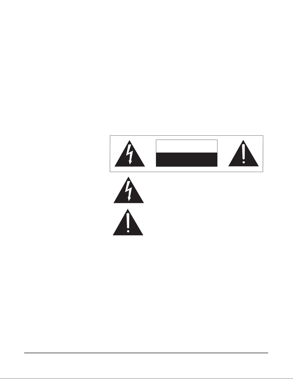
CAUTION
RISK OF ELECTRIC SHOCK
DO NOT OPEN
This symbol alerts you to the presence of uninsulated dangerous
voltage within the product's enclosure that might be of sufficient
magnitude to constitute a risk of electric shock. Do not open
the product's case.
This symbol informs you that important operating and maintenance instructions are included in the literature accompanying
this product.
Figure 1: Safety Symbols
8. Do not install near any heat sources such as radiators, heat registers, stoves, or
other apparatus (including amplifiers) that produce heat.
9. Do not defeat the safety purpose of the grounding-type plug. A grounding
type plug has two blades and a third grounding prong. The third prong is
provided for your safety. If the provided plug does not fit into your outlet,
consult an electrician for replacement of the obsolete outlet.
10.Protect the power cord from being walked on or pinched, particularly at
plugs, convenience receptacles, and the point where they exit from the
apparatus.
11.Only use attachments/accessories specified by the manufacturer.
12.Unplug this apparatus during lightning storms or when unused for long
periods of time.
13.Refer all servicing to qualified service personnel. Servicing is required when
the apparatus has been damaged in any way, such as if the power-supply cord
or plug is damaged, liquid had been spilled or objects have fallen into the
TW-60 PUBLIC SAFETY RADIO INTERFACE
i
Page 6

apparatus, the apparatus has been exposed to rain or moisture, does not
operate normally, or has been dropped.
14.Do not expose the apparatus to dripping or splashing and do not place objects
filled with liquids, such as vases, on the apparatus.
WA RN IN G: To reduce the risk of electric shock, do not expose this apparatus to
rain or moisture.
15.The appliance coupler is considered the disconnection device and should
remain readily operable for disconnection of unit.
ii
TW-60 PUBLIC SAFETY RADIO INTERFACE
Page 7

1
“Radio interoperability”
allows public safety
providers to talk in real time
on-demand regardless of the
brand, model number, or
frequencies of the radio
equipment used.
OPERATING A TW-60
INTRODUCTION
Thank you for choosing this Clear-Com product.
“Radio interoperability” is the ability of public safety providers – law
enforcement, firefighters, EMS, emergency management, public utilities,
transportation and other personnel – to exchange voice communications on
demand, in real time. It is the term that describes how radio communications
systems should operate between and among agencies and jurisdictions that
respond to common emergencies. Communication should be achieved regardless
of the brands, model numbers, or frequency ranges of the radio equipment used.
The TW-60, in conjunction with an associated Clear-Com matrix
communications system, can be installed with an existing Land Mobile Radio
communications system to provide interoperability.
Please read this manual completely to better understand the functions of the
TW-60. This manual is to be used in conjunction with the manuals supplied for
the associated Clear-Com matrix communications system. For questions not
addressed in this manual, contact your dealer, distributor, or Clear-Com directly.
Our applications support and service people are ready to help.
Channel 1
Audio
Level
Adj.
Receive
1.5
1
0.75
0.5
0.25
Transmit Delay
(Seconds)
DESCRIPTION
The TW-60 Public Safety Radio Interface provides the physical interface point to
connect a Land Mobile Radio to a Clear-Com matrix communications system. It
provides the necessary control and voice connections, including the ability to
delay the retransmission of voice to allow for the key up time on the
retransmitting radio. Each 1RU TW-60 provides and powers four separate radio
interface channels.
FRONT PANEL CONTROLS AND INDICATORS
TW-60 Interface
Key
Level
Transmit
Level
Adj.
Power
Fault
Figure 1: Front Panel of TW-60 Interface
Level
Level
Adj.
Transmit
Channel 4
Key
Audio
Level
Adj.
Receive
1.5
1
0.75
0.5
0.25
Transmit Delay
(Seconds)
2
2.5
3
4
5
Auto
0
2
2.5
5
Auto
0
Channel 2
Key
3
Level
4
Transmit
Level
Adj.
Audio
Level
Adj.
Receive
1.5
1
0.75
0.5
0.25
Transmit Delay
(Seconds)
2
2.5
3
4
5
Auto
0
Key
Level
Level
Adj.
Transmit
Channel 3
Audio
Level
Adj.
Receive
1.5
1
0.75
0.5
0.25
Transmit Delay
(Seconds)
2
2.5
3
4
5
Auto
0
TW-60 PUBLIC SAFETY RADIO INTERFACE
1-1
Page 8
• Receive Level Adjust: Used to adjust the receive level of the base station
two-way radio when there is no external volume control on the base station
radio.
Note: The receive level is set at the factory and should be adjusted only if the
remote radio does not have its own volume adjustment. The default is 12
o'clock, (1/2 rotation).
• Transmit Level Adjust: Use the TRANSMIT LEVEL ADJUST volume control
to set the level of the intercom's audio as heard at the remote station radio. The
factory default is 12 o'clock, (1/2 rotation).
• Transmit Delay: This rotary switch enables and adjusts the key up delay
available for each two-way radio. The available settings are shown in Table 1.
• Audio LED: This green LED illuminates when the system has sensed audio
from another channel and is supplying audio to this channel to be retransmitted.
• Key LED: This red LED illuminates when this channel is keying its associated
transmitter.
• Level LED: This bi-color red/green LED indicates audio levels received into
the system. Use this indicator to adjust the volume control on the two way radio
to match the system levels. The LED turns red when the signal is too high. Note
that proper audio levels cause the LED to light green when speaking, but flash
red about 10 percent of the time.
Power
40 MA (kfjakf) jljfakjakjf
100-250 VAC
Matrix GPI
• Power LED: This green LED illuminates when the system is receiving AC
power and is turned on.
• Fault LED: This red LED illuminates when the system is receiving AC power
and is turned on, but it has detected a problem with one of its internal power
supplies. The TW-60 may still operate in this condition, but service is required
to correct this condition.
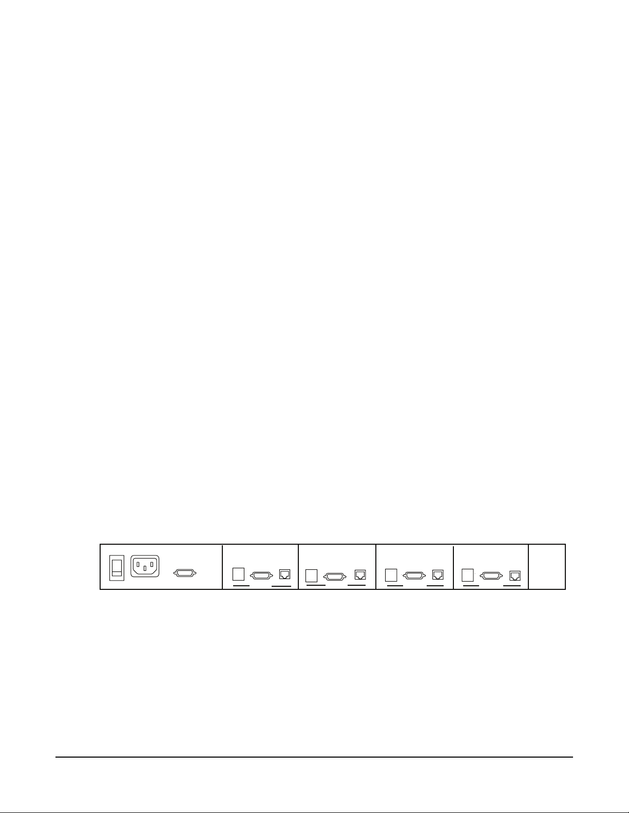
REAR PANEL CONTROLS AND INDICATORS
Setup
Switches
1,2,3
Two-Way
Radio
Channel 4
Matrix
Audio
Setup
Switches
1,2,3
Two-Way
Radio
Channel 3
Matrix
Audio
Setup
Switches
1,2,3
Two-Way
Radio
Channel 2
Figure 2: Back Panel of TW-60 Interface
• Power Switch: This switch turns the TW-60 on or off.
• IEC Power Inlet Connector: The AC power cord connects to this receptacle.
• Matrix GPI Connector: DB-9M connector used to connect control and audio
signals to the Clear-Com matrx.
Matrix
Audio
Setup
Switches
1,2,3
Two-Way
Radio
Channel 1
Matrix
Audio
1-2
TW-60 PUBLIC SAFETY RADIO INTERFACE
Page 9

• Channel 1 - 4 Radio Connectors: These four DB-9F connectors are used to
connect control and audio signals to the base station two-way radios on each
channel.
• Channel 1 - 4 Matrix Audio Connectors: These four RJ-45 connectors are
used to connect the 4-wire audio signals to the Matrix port.
• Channel 1 - 4 Setup Switches: These 3 dipswitches on each channel control
the audio level interface and transmitter keying protocol for each two-way radio.
Refer to Table 3.
TRANSMIT DELAY
For each of the four interface channels, a knob is provided on the front panel to
set the amount of time that audio will be delayed before it is transmitted. The
Transmit Delay is adjustable as follows:
POSITION ACTION
0 Delay is off, speech transmits immediatley
0.25 Delay is 0.25 seconds
0.5 Delay is 0.5 seconds
0.75 Delay is 0.75 seconds
1Delay is 1 second
1.5 Delay is 1.5 seconds
2Delay is 2 seconds
2.5 Delay is 2.5 seconds
3Delay is 3 seconds
4Delay is 4 seconds
5Delay is 5 seconds
Auto Delay is adjusted automatically
Table 1: Transmit Delay Switch Positions
In many trunking radio systems, the delay from keying a transmitter to having a
voice channel ready for use may be variable. The Automatic Transmit Delay
setting is useful in this situation to provide the minimum delay necessary for a
complete voice transmission. When set to automatically delay the transmitted
voice, the TW-60 listens for the tones the two way radio is producing and delays
the transmission of the voice until the tones stop.
TW-60 PUBLIC SAFETY RADIO INTERFACE
1-3
Page 10

1-4
TW-60 PUBLIC SAFETY RADIO INTERFACE
Page 11

2
You can wire the TW-60 to
a wide variety of two-way
radio audio and control
connections.
INSTALLING A TW-60
There are eight basic steps to installing the TW-60 Public Safety Radio Interface:
1. Wire cables for connecting the TW-60 unit to radios.
2. Install the TW-60 unit in an equipment rack.
3. Connect the the TW-60 unit to power,
4. Connect the TW-60 unit to radios.
5. Connect the TW-60 unit to a Clear-Com matrix,
6. Connect the TW-60 unit to general-purpose outputs (GPIs).
7. Adjust tranmsit levels.
8. Verify operation of the system.
CONNECTION TO RADIOS
In order to accommodate the widest variety of 2-way radios, each interface
channel of the TW 60 has a 9-pin DB-9F connector which can be wired to a
wide variety of two-way radio audio and control connections. Wiring diagrams
for many two-way radios are supplied as examples of cable wiring. (See
addendum sheet) This will allow you to make a cable that will operate with your
particular radio(s). Each connector socket is labeled on the TW-60's back panel
as Two-Way Radio.
PIN FUNCTION
1 Earphone receive audio ground (shield)
2 Normally closed (NC) transmit key contact
3 Common (C) transmit key contact
4 Normally open (NO) transmit key contact
5 Microphone transmit audio ground (shield)
6 Earphone receive audio
7 Common (C) transmit key contact
8 Alternate transmit key / audio connection
9 Microphone transmit audio
Table 2: Two-Way Radio DB-9F Connections
The combination of setup switches, connector wiring and front panel "Transmit"
and "Receive" level controls assures correct level matching to virtually any radio.
A relay provides the required "Push-to-Talk" transmitter "keying" of the radio.
This relay is activated when the Clear-Com matrix communications system
TW-60 PUBLIC SAFETY RADIO INTERFACE
2-1
Page 12

commands it. The relay contacts, in conjunction with the cable wiring chosen,
allow for correct transmitter keying to virtually any type of radio.
In addition to the following table, refer to the Block Diagram section of this
manual for a simplified diagram showing the Two-Way Radio connections to the
DB-9F connectors.
WIRING THE TWO-WAY RADIO CABLE
To connect the base-station radio to the TW-60, you must build your own
custom connector cable. This involves several steps:
1. Obtain or make a cable using the kind of plug that fits your radio. Use single
conductor shielded wire for each cable. Miniature type stereo cable is a good
choice. Solder these cables to the DB-9 connector as shown in Example 1.
This cable length should be kept less than 5 feet. A good source of molded
connectors for your radio would be an external microphone or earphone
which can be purchased from your radio supplier. You will need to cut off the
microphone or earphone as it will not be needed.
2. The next step will be to set the type and level of microphone. The TW-60 has
three Setup Switches for each interface channel that can be set for specific
types of microphones. The three illustrations that follow show how the
TW-60 switches and the male DB-9 connector on the channel cable are
configured for most radios. The section that follows, "Setup Switches," gives
instructions for setting the TW-60's Setup Switches.
3. The most difficult setting is often getting your particular radio to key properly.
Every radio has a different method of externally keying its transmitter. To
determine how to set the jumpers and wire the connector, you need to know
what type of external microphone is used in your radio, or you need to
experiment. Below are three examples of how to key the transmitter. If you are
unsure of which wiring to use, try all three, one at a time. Pins 2, 3, 4 and 7
are the relay contacts in the TW-60. If your radio model is not listed in the
addendum sheet and you have tried all three examples, but you still can't
make the two-way radio work properly, call customer service and we will help
you get the system working.
SETUP SWITCHES
Table 3 shows the location of the Setup Switches on the back panel. There is one
set of three for each of the four channels. The switches are set to ON when they
are in the down position and are set to OFF when they are in the up position.
Output Level Switches: Set switches 2 or 3 to ON to lower the signal level to the
two way radio's microphone input. The switches change the levels, as shown in
Table 3. In general, set switch 3 to ON for most low-level mics (for example,
electrets): set both switches 2 and 3 ON to further reduce the input level for
dynamic type mics.
TW-60 PUBLIC SAFETY RADIO INTERFACE
2-2
Page 13

Transmit Key Switch: For some two-way radios, a dedicated power path may be
needed to activate the Transmit function. If so, set switch 1 to ON, as shown in
Table 3.
SWITCH 1 SWITCH 2 SWITCH 3 FUNCTION
Off Off Mic input range is + 11 dBv to - 20 dBv
Off On Mic input range is - 26 dBv to - 48 dBv
On On Mic input range is - 30 dBv to - 57 dBv
On Provides a dedicated power path to key Transmit
Off Removes power path
Table 3: Setup Switch Positions
RACK MOUNTING
The unit requires 1.75 inches (44 mm) (1RU) of rack space. It requires no
additional free rack space above or below it for ventilation. The station is 5.25
inches (133 mm) in depth and requires at least 2 1/2 inches clearance in the rear
for connectors and cables. The single-piece front panel has integral "rack ears".
This adds stability and strength. Take care not to over tighten the rack mounting
screws as this can mar the front panel.
CONNECTING THE TW-60
Make the necessary back panel connections to the TW-60:
1. Plug the power cord into the IEC receptacle of the TW-60 and connect the
power cord to an unswitched AC outlet.
2. Connect the two-way radio cables from the DB-9F connectors on the TW-60
to each two-way radio.
3. Using 730239 cables, connect the Channels 1 through 4 Matrix Audio
Connectors of the TW-60 to the appropriate connectors on the Clear-Com
matrix. As can be seen in Table 4, four of these cables are needed for each
TW-60 unit.
4. Using a 730240 or a 730241 cable, connect the GPI cable from the DB-9M
connector on the TW-60 to the DB-25F GPI connector on the Clear-Com
matrix. Use the cable shown in Table 4 for each TW-60 unit. Each cable
serves two units.
TW-60 PUBLIC SAFETY RADIO INTERFACE
2-3
Page 14

TW-60 UNITS 730239 CABLES 730240 CABLES 730241 CABLES
Channels 1 - 4 4 1
Channels 5 - 8 4
Channels 9 - 12 4 1
Channels 13 - 16 4
Table 4: Matrix Cables Required for Each TW-60 Unit
The matrix audio RJ-45 jack pinout from the TW-60 to the Clear-Com matrix
communications system is as follows:
PIN FUNCTION
1Not used
2Not used
3 Audio to matrix +
4 Audio from matrix +
5 Audio from matrix -
6 Audio to matrix -
7Not used
8Not used
Table 5: Matrix Audio RJ-45 Jack Pinout
TW-60 PUBLIC SAFETY RADIO INTERFACE
2-4
Page 15

The Matrix GPI DB-9M jack pinout from the TW-60 to the Clear-Com matrix
communications system is as follows:
PIN FUNCTION
1 Channel 1 matrix GPI control
2 Channel 2 matrix GPI control
3 Channel 3 matrix GPI control
4 Channel 4 matrix GPI control
5Signal return
6 Chassis ground
7 Chassis ground
8 Chassis ground
9 Chassis ground
Table 6: Matrix GPI DB-9M Jack Pinout
VERIFYING OPERATION OF THE TW-60 SYSTEM
After the interconnections have been made, and programmed with the
Clear-Com matrix communications system as described in its manuals, it is now
time to check that everything is working properly:
1. Using the documentation supplied with the Clear-Com matrix
communications system as a guide, place all of the radio interfaces into one
group.
2. Turn on the base station two-way radio and the remote radio. Make sure you
have fresh or fully charged batteries. With the external jacks on the base
station removed, make sure the radios can communicate with each other.
3. Set all the Receive Level and Transmit Level controls on the TW-60 to their
mid position. Set the Transmit Delay Switch for each channel to 0.
4. Turn on the TW-60 using the power switch on the back panel. The green
power indicator on the front panel should light and the red fault indicator
should be off.
5. Set the base station two-way radio volume control to approximately zero
volume. Key the remote radio associated with the base station radio.
Gradually increase the volume control on the base station two-way radio until
the green Audio light on the channel associated with that radio lights. The
volume control should be set to the minimum level that will light the green
Audio light with the sound of the radio unsquelching.
6. Repeat the previous step for each radio on the other channels.
7. When the volume controls have been correctly adjusted, keying any remote
radio should result in the Audio LED lighting on the associated TW-60
channel and also in the Transmit Key LEDs lighting on the other TW-60
TW-60 PUBLIC SAFETY RADIO INTERFACE
2-5
Page 16

channels. The transmit indicator on the base station radios (if any) on these
channels should also illuminate.
8. Now verify that when any remote radio is keyed, the others can all hear the
transmission. To avoid feedback, it is helpful to have the remote radios some
distance away or in another room. The Transmit Level controls on the TW 40
adjust the volume to the remote radios. If the audio heard on any remote radio
is too loud or too weak, adjust the Transmit Level control for that radio on its
associated TW-60 channel. While speaking on the remote radio, the Transmit
Level LED on the other channels should be flashing green with some
occasional red. You may need to adjust the Setup Switches on the
transmitting channel to set the audio signal to the level needed by the mic
circuit of that radio. Adjust switches 2 and 3 as described in Table 3.
9. You should now be able to communicate from any remote radio to the other
remote radios. Pressing the talk key on each remote transmitter should key any
other base station transmitter channels in the same group. Note whether the
key up time of any given channel prevents the first words from being received.
If the first words are missed on any channel(s), turn the Transmit Delay
Switch for that channel to add more audio delay. Adjust for the minimum
delay that consistently transmits the first words promptly and correctly. For
trunking radio systems which have an inconsistent delay that varies depending
upon conditions, set the Transmit Delay Switch to Auto.
10.If there are other TW-60 units in the system, program each one using the
above steps. When all have been programmed, verify that any radio channel
on any TW-60 can be retransmitted onto all of the other channels on all of
the TW-60 units.
TW-60 PUBLIC SAFETY RADIO INTERFACE
2-6
Page 17

3
TECHNICAL REFERENCE
BLOCK DIAGRAM
The following block diagram shows only two of the four channels.
Figure 1: Block diagram of two channels
TW-60 PUBLIC SAFETY RADIO INTERFACE
3-1
Page 18

TW-60 PUBLIC SAFETY RADIO INTERFACE
3-2
Page 19

4
SPECIFICATIONS
Transmit Output
To radio microphone Transformer isolated
Microphone Type Carbon, dynamic or electret
Level: -57 dBv to +11 dBv *
Frequency Response 100 - 15,000 Hz, ±3 dB
Transmit Key N.O. or N. C. dry contacts
Transmit Audio Delay 0 to 5 seconds in 12 steps
Receive Input
From radio earphone: Transformer isolated
Impedance: 400 ohms balanced. Level: -8 dBv to +23 dBv *
Frequency Response 100 - 15,000 Hz, ±3 dB
Rear Panel Connectors
Two-Way Radios (4) DB-9F (1 per channel)
Matrix Audio (4) RJ-45 (1 per channel)
Matrix GPI Control (1) DB-9M
AC Power (1) IEC 320 connector
Rear Panel Controls
Power Switch (1) Rocker switch
Front Panel Controls
Receive Level Adjust (4) Trimpots (1 per channel)
Transmit Level Adjust (4) Trimpots (1 per channel)
Transmit Delay (4) 12-position rotary switch (1 per channel)
Front Panel Indicators
Receive Audio (4) Green LEDs (1 per channel)
Transmit Key (4) Red LEDs (1 per channel)
Transmit Audio Level (4) Red/Green LEDs (1 per channel)
Power On (1) Green LED
Power Fault (1) Red LED
Power Requirements
100-250 VAC, 50 - 60 Hz, 70 W (max)
Environmental
32 - 122° F (0 - 50° C)
TW-60 PUBLIC SAFETY RADIO INTERFACE
4-1
Page 20

Dimensions
19 inches W x 1.75 inches H x 5.25 inches D (483 mm x 44 mm x 133 mm)
Weight
4.5 lbs. (2.05 kg)
* 0 dBv is referenced to 0.775 volts RMS.
Notice About Specifications
While VGC Clear-Com makes every attempt to maintain the accuracy of the
information contained in its product manuals, that information is subject to
change without notice. Performance specifications included in this manual are
design-center specifications and are included for customer guidance and to
facilitate system installation. Actual operating performance may vary.
TW-60 PUBLIC SAFETY RADIO INTERFACE
4-2
Page 21

5
Clear-Com offers 24/7
customer support.
Return authorization
numbers are required for all
returns.
WARRANTY
Clear-Com guarantees this product to be free of manufacturing defects in
material and workmanship under normal use for a period of two years from the
date of purchase.
TECHNICAL SUPPORT
To ensure complete and timely support to its customers, Clear-Com maintains
Technical Service Centers (TSC) staffed by qualified technical personnel. A
Technical Service Center is staffed to respond to all technical inquiries and to
troubleshoot technical problems regarding all products supplied by Clear-Com.
A TSC is fully available to Clear-Com’s customers during the full course of their
warranty period.
Instructions for reaching our Technical Service Centers are given below.
For technical support from Europe, the Middle East, and Africa
Both warranty and
non-warranty repairs are
available.
Call: +49 40 66 88 40 40 Monday through Friday 09:00 – 17:00 (GMT)
+49 40 66 88 40 41 24hrs, any day (But you must have your PIN number
ready.)
Web si t e: www.clearcom.com
For technical support from the Americas and Asia
Call: +1 510 496 6666
Web site: www.clearcom.com
FAX: +1 510 496 6610
EXCEPTIONS
This warranty does not include damage to a product resulting from cause other
than part defect and malfunction. The Clear-Com warranty does not cover any
defect, malfunction, or failure caused beyond the control of Clear-Com,
including unreasonable or negligent operation, abuse, accident, failure to follow
instructions in the manual, defective or improperly associated equipment,
attempts at modification and repair not approved by VGC, and shipping
damage. Products with their serial numbers removed or defaced are not covered
by this warranty.
WARRANTY
WARRANTY REPAIRS
While Clear-Com will ensure complete system integrity by providing whatever
support is necessary to resolve any failure covered under the terms of the
warranty, the normal procedure will be to repair or replace any defective Line
5-1
Page 22

Replaceable Unit (LRU) that is returned to Clear-Com during the warranty
period.
A Line Replaceable Unit (LRU) is defined as: an assembly that can be safely
removed from the system and readily replaced by plugging in a new unit. In the
case of ancillary items such as power supplies, the entire power supply would be
returned. Whereas, in the case of circuit cards, control panels, etc., only these
assemblies would be returned for repair. All equipment provided by Clear-Com
is covered under the warranty.
This warranty does not include defects arising from installation (when not
performed by Clear-Com), lightning, power outages and fluctuations, air
conditioning failure, improper integration with non-approved components,
defects or failures of customer furnished components resulting in damage to
Clear-Com provided product.
NON-WARRANTY REPAIRS
Equipment that is not under warranty must be sent prepaid to Clear-Com. If
requested, an estimate of repair costs will be issued prior to service. Once repair is
approved and completed, the equipment will be shipped freight collect from the
TSC.
REPLACEMENT UNITS
Should Clear-Com determine, in its reasonable discretion, that any part of a
product is defective due to faulty materials or workmanship, Clear-Com shall at
its expense, repair or replace such part and return the repaired/replacement part
to the customer. The provisions of this warranty shall apply to the
repaired/replacement part for the unexpired portion, if any, of the warranty
period.
EMERGENCY ON-SITE ASSISTANCE
Clear-Com can provide emergency on-site technical assistance in support of
warranty activities. The level of support effort required will be decided on a
case-by-case basis. Clear-Com has the qualified technical staff to support any and
all emergency site activities should they occur.
LIABILITY
The foregoing warranty is Clear-Com’s sole and exclusive warranty. There are no
other warranties (including without limitation warranties for consumables and
other supplies), or guarantees, expressed or implied (including, without
limitation, any warranties of merchantability or fitness for a particular purpose),
of any nature whatsoever, whether arising in contract, tort, negligence of any
degree, strict liability or otherwise, with respect to the products or any part
thereof delivered hereunder and/or with respect to any non-conformance or
defect in any such product and/or part thereof delivered hereunder and/or with
respect to any non-conformance or defect in any such product and/or part
WARRANTY
5-2
Page 23

thereof delivered hereunder, or any other warranties or guarantees, including but
not limited to any liability of Clear-Com for any consequential and/or incidental
damages and/or losses (including loss of use, revenue, and/or profits). In any
event, the maximum extent of Clear-Com’s liability to customer hereunder shall
not under any circumstances exceed the cost of repairing or replacing any part(s)
found to be defective within the warranty period as aforesaid.
RETURNING EQUIPMENT FOR REPAIR
All equipment returned for repair must be accompanied by:
• Documentation stating the return address, telephone number, date of
purchase, and a description of the problem.
• A repair reference number.
To obtain a repair reference number, contact the appropriate Technical Service
Center at the phone numbers or Web sites listed below. Our representatives will
give you instructions and addresses for returning your equipment. By talking
with our representatives, many problems can be resolved on the phone.
For returns from Europe, the Middle East, and Africa
Call: +49 40 66 88 40 40 Monday through Friday 09:00 – 17:00 (GMT)
+49 40 66 88 40 41 anytime, any day
(But you must have your PIN number ready)
Web site: www.clearcom.com
For returns from the Americas and Asia
Call: +1 510 496 6666
Web site: www.clearcom.com
FAX: +1 510 496 6610
WARRANTY
5-3
Page 24

WARRANTY
5-4
 Loading...