


HT-E

UNDERCOUNTER DISHMACHINES
DRAFT
INSTALLATION, OPERATION,
AND SERVICE MANUAL
HT-E
HT-E Manual • 07610-004-64-85-A


REVISION HISTORY
Revision
Letter
A DRAFT JH N/A DRAFT
Revision
Date
Made by Applicable ECNs Details
iii

NOMENCLATURE
HT-E
Undercounter dishmachine; high-temperature, hot-water
sanitizing, with a booster tank, drain pump, and
detergent and rinse-aid dispensers.
The manufacturer provides
technical support for the
dishmachine detailed in
this manual. We strongly
recommend that you refer to
this manual before making a
call to our technical support
sta. Please have this manual
open when you call so that our
sta can refer you, if necessary,
to the proper page. Technical
support is not available
on holidays.
Contact technical support tollfree at 1-888-800-5672.
Technical support is available
for service personnel only.
iv

TABLE OF CONTENTS
GUIDES
Symbols ...................................................................................................................................... 1
Abbreviations .............................................................................................................................. 1
SPECIFICATIONS
Machine Dimensions .................................................................................................................. 2
Operating Parameters ................................................................................................................ 3
Electrical Requirements ............................................................................................................. 4
INSTALLATION
Installation Instructions ............................................................................................................... 5
Inspection......................................................................................................................... 5
Unpacking ........................................................................................................................ 5
Plumbing .......................................................................................................................... 5
Water Supply Connections .............................................................................................. 5
Pressure Regulator .......................................................................................................... 6
Shock Absorber ............................................................................................................... 6
Connecting the Drain Line ............................................................................................... 6
Plumbing Check ............................................................................................................... 6
Electrical Power Connections .......................................................................................... 7
Voltage Check .................................................................................................................. 7
Surrounding Area ............................................................................................................. 7
Thermostats ..................................................................................................................... 8
Chemical Feeder Equipment ........................................................................................... 8
Priming Chemical Feeder Pumps .................................................................................... 8
Leveling............................................................................................................................ 8
OPERATION
Operating Instructions ................................................................................................................ 9
Preparation ......................................................................................................................9
Filling the Wash Tank ....................................................................................................... 9
Ware Preparation ............................................................................................................. 9
Washing a Rack of Ware ...............................................................................................10
Operational Inspection ................................................................................................... 10
Alarms ............................................................................................................................ 10
Draining.......................................................................................................................... 11
Shutdown & Cleaning .................................................................................................... 11
Deliming ......................................................................................................................... 13
Detergent Control...........................................................................................................14
v

TABLE OF CONTENTS
MAINTENANCE
Preventative Maintenance ........................................................................................................ 15
Drain Pump Cleanout ............................................................................................................... 15
TROUBLESHOOTING
Troubleshooting ........................................................................................................................ 16
PARTS
Tub & Frame ............................................................................................................................. 18
Electrical ................................................................................................................................... 20
Hoses ....................................................................................................................................... 22
Wash & Rinse Arms .................................................................................................................. 24
Plumbing Options ..................................................................................................................... 26
Miscellaneous Parts ................................................................................................................. 27
SCHEMATICS
208-230 V, 60 Hz, 1 Phase ....................................................................................................... 28
vi
GUIDES
NOTICE
SYMBOLS
- Risk of Injury to Personnel
!
WARNING
- Risk of Damage to Equipment
!
CAUTION
- Risk of Electrical Shock
- Caustic Chemicals
- Reference Data Plate
i
GUIDES
- Lockout Electrical Power
- Important Note
- Instructions Hyperlink
ABBREVIATIONS & ACRONYMS
ANSI - American National Standards Institute
CFM - Cubic Feet per Minute
dBA - Decibels Adjusted
GHT - Garden Hose Thread
GPH - Gallons per Hour
GPM - Gallons per Minute
GPG - Grains per Gallon
HP - Horse Power
Hz - Hertz
ID - Inside Diameter
kW - Kilowatts
MCA - Minimum Circuit Ampacity
MOP - Maximum Overcurrent Protection
NFPA - National Fire Protection Association
NPT - National Pipe Thread
OD - Outside Diameter
PRV - Pressure Regulating Valve
PSI - Pounds per Square Inch
V - Volts
07610-004-64-85-A
1
SPECIFICATIONS
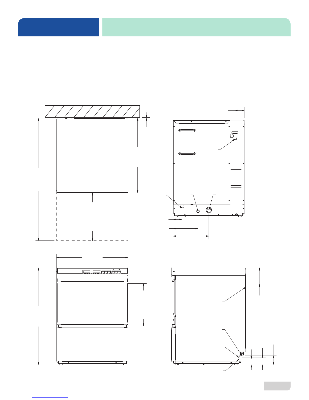
LEGEND
A - Electrical Connection
B - Water Inlet (connection actually at end of pre-installed hose)
C - Drain Connection
D - Chemical Connection
All dimensions from the floor can be increased
2” using the machine’s adjustable feet.
]
m
/2
m
1
9
0
2
4
0
1
[
MACHINE DIMENSIONS
[79 mm]
]
m
/4
m
1
7
[
]
m
4
/
m
3
9
4
2
2
TOP BACK
[6
B
3 1/8
A
N
]
E
P
m
4
/
O
m
3
0
R
5
0
1
O
[4
O
D
23 3/4
[603 mm]
4
]
m
/8
m
1
6
2
1
3
[8
FRONT SIDE
1
[76 mm]
[210 mm]
E
]
C
m
N
A
m
R
6
A
5
E
[3
L
C
3
8 1/4
D
11 7/8
[302 mm]
C
B
A
C
]
m
8
/
m
3
2
6
6
[1
]
]
]
8
m
/
8
/
3
7
m
2
8
1
[4
m
m
3
m
6
m
0
[7
[6
07610-004-64-85-A
D
2

SPECIFICATIONS
NOTICE
OPERATING PARAMETERS
Operating Capacity (without Load Time): HT-E
Racks per Hour 32
Dishes per Hour 800
Glasses per Hour 1152
Operating Capacity (with Load Time):
Racks per Hour 25
Dishes per Hour 625
Glasses per Hour 900
Tank Capacity (Gallons):
Wash Tank XX
Booster Tank XX
Electrical Loads (as applicable):
Wash Motor HP 3/4
Wash Heater kW (208 V) 3.2
Wash Heater kW (230 V) 4.5
Booster Heater kW (208 V) 3.9
Booster Heater kW (230 V) 5.5
i
Always refer to the machine data plate for specic electrical and water requirements.
The material provided on this page is for reference only and is subject to change
without notice.
Sound Level:
Workplace-related Emission Value (dBA) 66
Water Temperatures (°F):
Minimum Wash Temperature 150
Minimum Rinse Temperature 180
Minimum Incoming Water Temperature 110
Water Consumption:
Gallons per Rack 0.69
Gallons per Hour 22.1
Other Water Requirements:
Water Flow Pressure (PSI) 20 ± 5
Flow Rate Minimum (GPM) 4.6
Water Line Connection Size 3/4" GHT
Water Line Size (NPT) 1/2"
Drain Line Size (NPT) 1" ID
1 3/8" OD
07610-004-64-85-A
3
SPECIFICATIONS
NOTICE
i
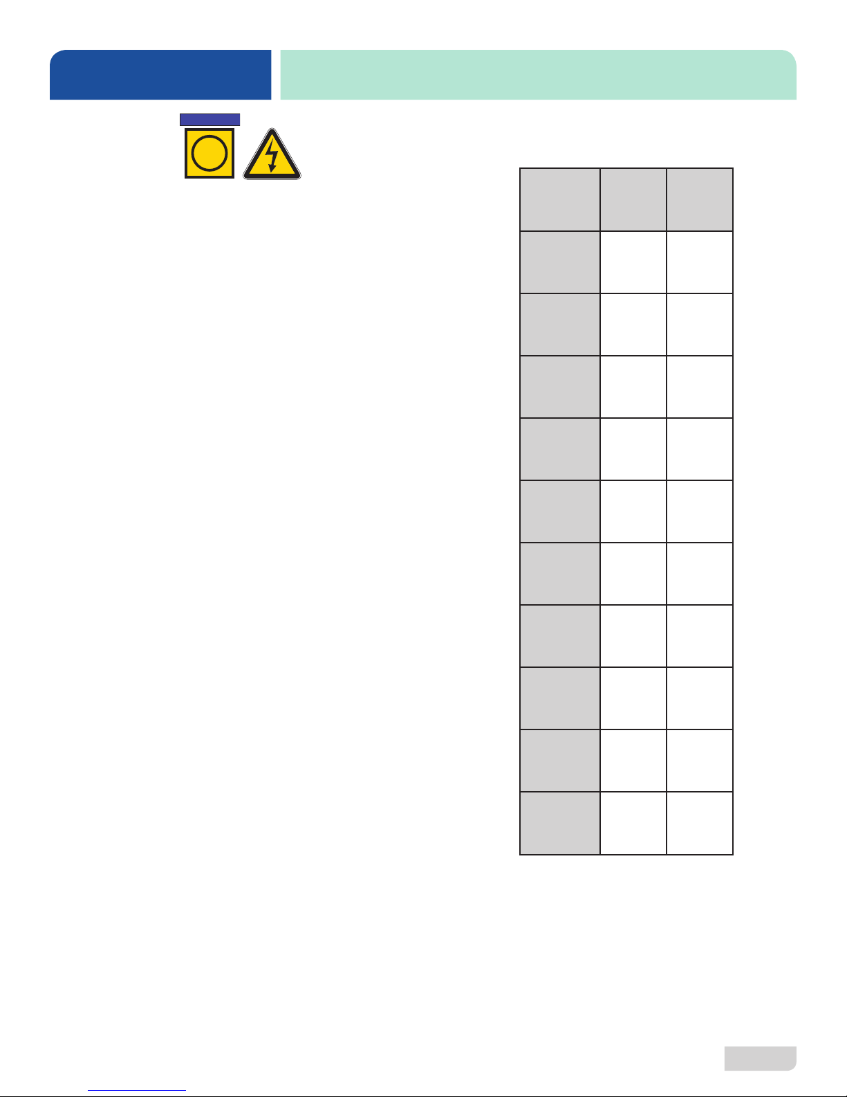
ELECTRICAL REQUIREMENTS
Electrical Characteristics
HT-E
All electrical ratings provided in this manual are for reference
only. Always refer to the machine data plate to get exact electrical
information for this machine. All electrical work performed on
machines should be done in accordance with applicable
local, state, territorial, and national codes. Work should only
be performed by qualied electricians and authorized service
agents.
Note that all electrical wiring used in the HT-E must be rated, at
a minimum, for 212 °F (100 °C), and that only copper conductors
must be used.
Where applicable, heating element amperage draws have been
adjusted for the assumed input voltage. The manufacturer
assumes incoming voltages will be either 208 or 230 Volts. Some
heating elements used in the machines are rated for other voltages,
such as 240 Volts and 480 Volts. Always verify the amperage
draw of the machine in operation when sizing circuit protection.
Available Electrical Characteristics:
• 208 V, 60 Hz, Single-phase
• 230 V, 60 Hz, Single-phase
VOLTS 208 230
PHASE 1 1
FREQ 60 60
WASH
MOTOR
AMPS
DRAIN
MOTOR
AMPS
RINSE
MOTOR
AMPS
WASH
HEATER
AMPS
BOOSTER
HEATER
AMPS
3.8 A 3.8 A
0.3 A 0.3 A
1.8 A 1.8 A
15.2 A 16.8 A
21.7 A 24.0 A
07610-004-64-85-A
TOTAL
LOAD
MCA 26.8 A 28.8 A
MOP 30.0 A 30.0 A
25.8 A 27.8 A
4

INSTALLATION
Shut-off
Adapter AdapterSPS Machine
Facility
INSTRUCTIONS
INSPECTION
Do not throw away
packaging if damage is
evident!
UNPACKING
PLUMBING
The plumber must ush
the incoming water line!
Before installing machine, check packaging and machine for damage. Damaged
packaging might be an indication of damage to the machine. If there is any type
of damage to both packaging and machine, do not throw away the packaging. The
machine has been inspected at the factory before shipping and is expected to arrive
in new, undamaged condition. However, rough handling by carriers or others might
result in damage to the machine while in transit. If this occurs, do not return machine to
the manufacturer. Instead, contact the carrier and ask them to send a representative
to the site to inspect the damage and request that an inspection report be completed.
Contact the carrier within 48 hours of receiving the machine as well as the dealer that
sold you the machine.
The machine should be unpacked and removed from the pallet before installing. Open
the front door and remove all materials from inside. Once unpacked, verify there are no
missing parts. If a part is missing, contact the manufacturer immediately.
All plumbing connections must adhere to local, state, territorial, and national codes.
The installing plumber is responsible for ensuring the incoming water lines are ushed
of debris before connecting to the machine. Note that chips and materials from cutting
processes can become lodged in the solenoid valves and prevent them from opening
or closing. Any valves found to be fouled or defective because of foreign matter
left in the water line, and any subsequent damage, are not the responsibility of the
manufacturer.
A water hardness test
must be performed.
WATER SUPPLY
CONNECTIONS:
WATER HARDNESS
HIGHER THAN 3 GPG
i
A water hardness test must be performed. If water hardness is higher than 3 GPG,
install a water softener or install the optional Scale Prevention System (SPS). See the
next section and the Plumbing Options page for more information on the SPS.
If water hardness is higher than 3 GPG and a water softener is not being used, install
the SPS into the water line between the facility water line and machine water line.
Observe proper inlet/outlet water directions. A water shut-o valve should be installed
before installing the SPS to allow access for service. The water supply must be
capable of the minimum “ow” pressure at the recommended temperature indicated
on the data plate.
Example
Water Line
Valve
*Adapters needed will vary.
Water Line
07610-004-64-85-A
5
 Loading...