

Page 1
®
Phoenix
Owner’s Manual
The instructions, specifications, and recommendations in this manual are based on current information when this
manual was released. Cleaire Advanced Emission Controls, LLC reserves the right to make changes at any time
without obligation. If you find differences between your system and the information in this manual, contact your
Cleaire dealer or call Cleaire at 1-800-308-2111.
The Cleaire logo, Cleaire Advanced Emission Controls, Allmetal, Horizon, Lonestar, LongMile, Longview,
Keep a copy of this Owner’s Manual in the equipment cab.
MLC and Phoenix are registered trademarks of Cleaire Advanced Emission Controls, LLC.
ATTENTION:
Page 2

This page intentionally left blank
Page 3

Cleaire Phoenix® Owner’s Manual
Table of Contents
General Information.................................................................................................................. 1
Cautions............................................................................................................................................................. 2
Safety Warnings ................................................................................................................................................ 2
Owner’s Legal Obligations................................................................................................................................. 3
Contact Information ........................................................................................................................................... 3
Installation.......................................................................................................................................................... 4
DPF Swapping ................................................................................................................................................... 4
System Re-Designation ..................................................................................................................................... 5
Engine Repower ................................................................................................................................................ 6
Acronyms ........................................................................................................................................................... 6
Phoenix System Description ................................................................................................... 7
Product Summary .............................................................................................................................................. 8
PM Filter Assembly ............................................................................................................................................ 9
Control System ................................................................................................................................................ 10
Regeneration System ...................................................................................................................................... 11
Low-Voltage Switch (Optional) ........................................................................................................................ 13
CARB-Verification Labels ................................................................................................................................ 13
Operations ............................................................................................................................... 14
Pay Attention to the System, Engine and Equipment ..................................................................................... 15
Regenerating the Phoenix ............................................................................................................................... 15
Operator Interface Module............................................................................................................................... 16
Conditions That May Damage the Phoenix ..................................................................................................... 19
Maintenance and Repair ........................................................................................................ 20
Your Right to Maintenance Information ........................................................................................................... 21
The Importance of Engine Maintenance ......................................................................................................... 21
The Importance of Properly Maintaining a Diesel Emission Control Strategy ................................................ 21
Maintenance Schedule .................................................................................................................................... 21
Preventative Maintenance Labor and Parts .................................................................................................... 22
Service Calls .................................................................................................................................................... 23
Parts List .......................................................................................................................................................... 24
Troubleshooting ............................................................................................................................................... 25
Repair and Maintenance Clarifications ............................................................................................................ 27
Engine Oil Consumption and Lube Oil Ash ..................................................................................................... 28
Specifications ......................................................................................................................... 30
Owner’s Obligations ............................................................................................................... 33
Warranty .................................................................................................................................. 35
Product Warranty ............................................................................................................................................. 36
Installation Warranty ........................................................................................................................................ 37
Cleaire Warranty Clarifications ........................................................................................................................ 37
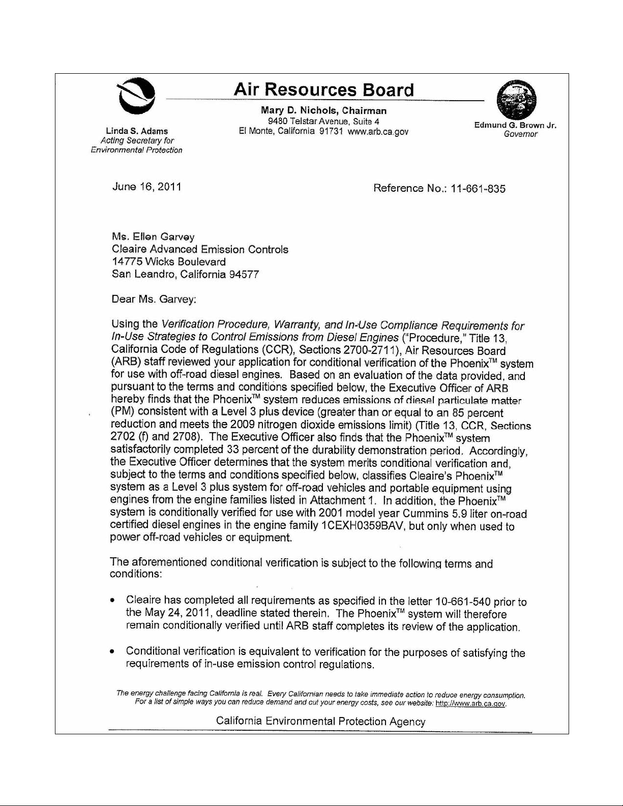
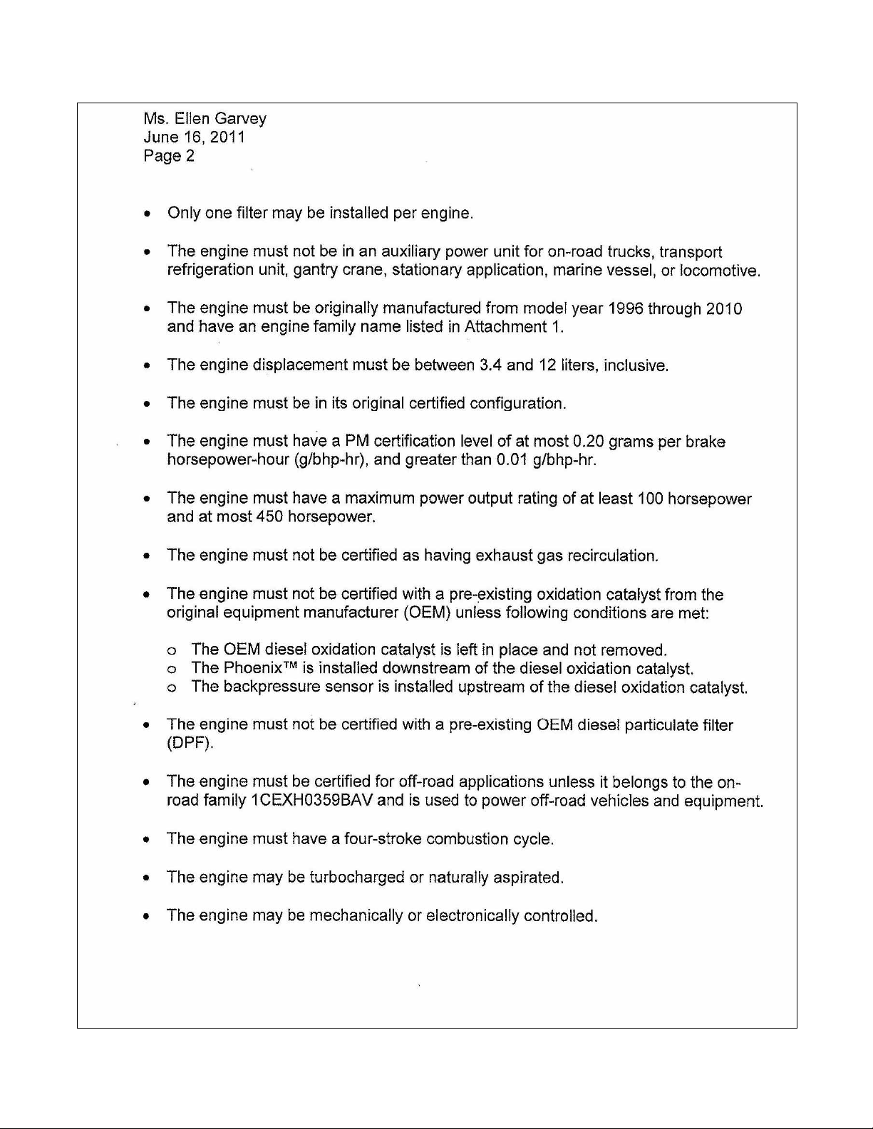
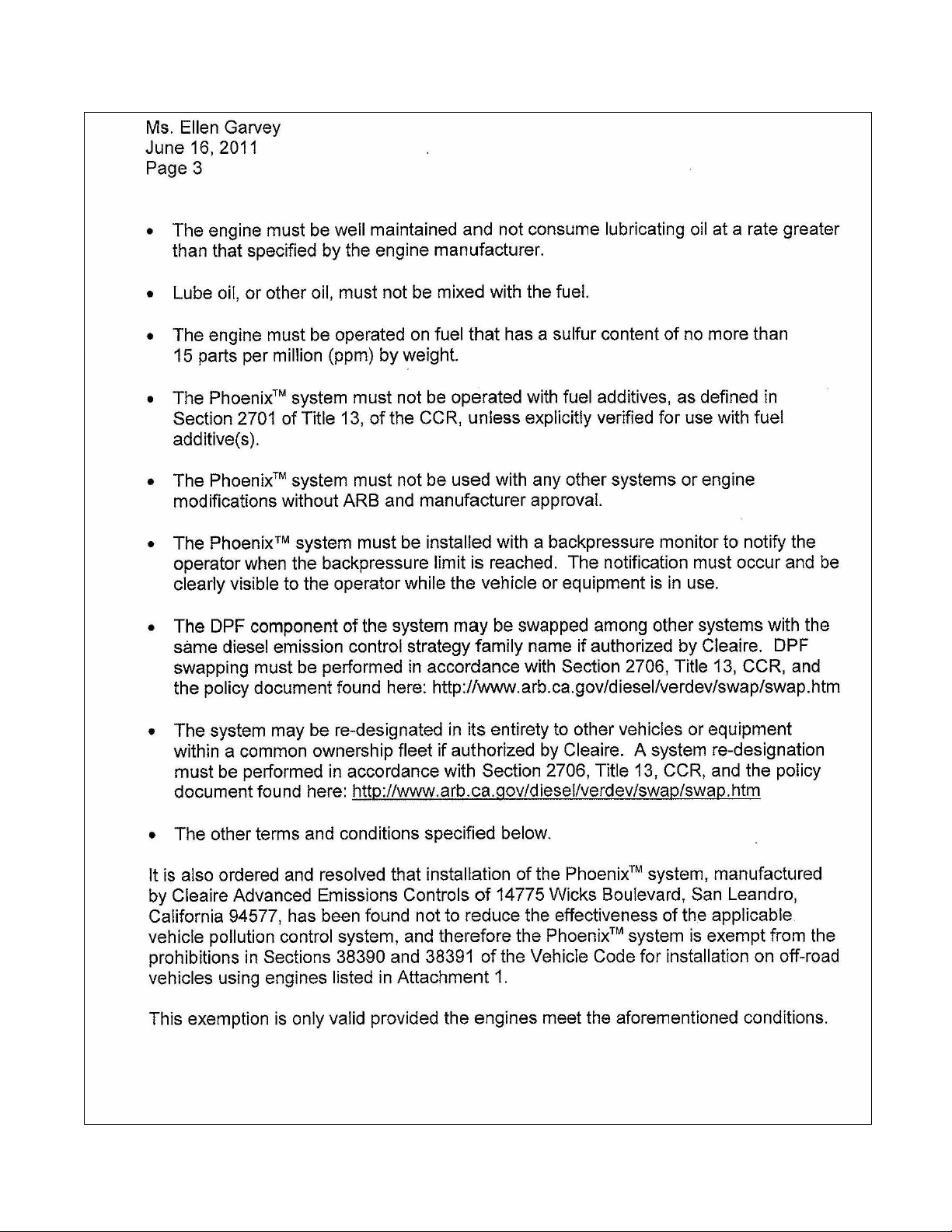
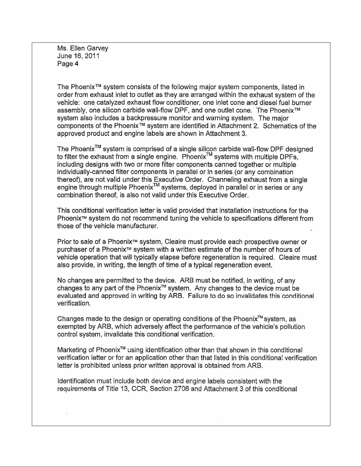
CARB Executive Order for the Phoenix ................................................................................ 38
Phoenix_Owner's_Manual-2011-06
Page 4

G
ENERAL INFORMATION
Phoenix_Owner's_Manual-2011-06 Page 1
Page 5

Cautions
Please study this manual and understand the requirements for the Cleaire Phoenix
system before operating your machine.
The pictures and descriptions in this manual are for a typical Phoenix system. Some parts,
components and configurations for your particular system may vary from those shown here
depending on the machine and application.
The use of parts which are materially different than the verified retrofit parts or systems may
void the verification and the warranty.
The owner’s obligations, routine observations and periodic maintenance requirements are
described in this manual. Contact a Cleaire dealer for further assistance.
Safety Warnings
• Before starting regeneration, park the machine on level ground in a well
ventilated location far away from any combustible material. Turn the engine off.
Do not regenerate indoors.
• The system may be hot when not normally expected:
o Caution: The Phoenix emits hot exhaust gases during regeneration.
o During regeneration, the engine will be off, but the Phoenix (including the
downstream pipes) will be very hot.
o The PM filter stays hotter much longer than a stock muffler will after
operating under heavy load, after the engine is turned off, and after a
completed regeneration cycle.
• Do not touch any of the PM filter assembly components or exhaust tubing during
regeneration or after engine operation. All surfaces can become hot and may
cause burns.
• After operating under heavy load, be very careful about operating or idling near
any combustible material such as dry grass or trash. The PM filter retains heat
much longer than a muffler which makes it possible for very hot exhaust gases to
exit the tailpipe for several minutes (after the high-load operation) and be a
potential source of ignition for any combustible material.
• Do not allow combustible material from the working environment to come in
contact with the Phoenix (for example, paper, trash, sawdust).
• Inspect regularly for any fuel leaks. If any are found, contact your dealer
immediately for further assistance.
• Be sure the Phoenix heat shield panels are in place. If any are missing, contact a
Cleaire-authorized dealer as soon as possible for service.
Phoenix_Owner's_Manual-2011-06 Page 2
Page 6

Owner’s Legal Obligations
Use of any alternative diesel fuels and or fuel additives not specifically listed in the CARB
verification Executive Order (E.O.) is illegal and strictly prohibited. Operating with an
unapproved alternative diesel fuel or fuel additive violates the E.O., negates the verification for
that equipment, and removes compliance status for the equipment. The end-user must meet
other requirements in the E.O. for the Phoenix which is provided in this manual beginning on
page 38. The E.O. for the Phoenix may also be obtained from the CARB website at
http://www.arb.ca.gov/diesel/verdev/level3/level3.htm.
The installation of the Phoenix is based on the owner’s understanding that adding a new part
to or altering an original part of a certified configuration could be considered a violation of the
tampering prohibition of the Clean Air Act. The owner understands that the installation of the
Phoenix will not violate tampering provisions of the Act, at the time of installation, because of
the testing performed under the verification process—provided that the owner adheres to all
installation instructions and meets all operating and maintenance requirements for the
Phoenix.
• Specific events that require action by the owner or operator are given in the
“Owner’s Obligations” section on page 33.
• If any of these events occur, it is the owner’s obligation to take the appropriate
action. Failure to do so may be the basis for denying a warranty claim.
Contact Information
Contact a Cleaire-authorized dealer for any sales or service support for your Phoenix system.
The tables below for contact information are provided for the customer to complete at their
convenience. For more information, contact your local Cleaire product support representative,
call Cleaire at 800-308-2111, or visit www.cleaire.com.
Dealer
Address
Contact person
Contact person’s phone
Contact person’s fax
Contact person’s email
Phoenix_Owner's_Manual-2011-06 Page 3
Page 7

Name of local Cleaire product
support representative
Local Cleaire representative’s phone
Local Cleaire representative’s email
Installation
Cleaire recommends that a Cleaire-authorized technician installs the Phoenix system. The
complete installation procedures are described in the Phoenix Installation Manual. Copies of
the manual are available upon request from your dealer. The installation warranty (page 37) is
the responsibility of the dealer that installs the Phoenix system.
Attention:
A Cleaire-certified technician must commission the system;
otherwise, that may be the basis for denying a warranty claim.
Warranty registration is submitted by the Cleaire-authorized dealer.
DPF Swapping
CARB defines component swapping as the movement of designated parts between different
vehicles/applications utilizing the same Diesel Emissions Control System (DECS). In this
case, Cleaire is limiting this process only to swapping of the diesel particulate filter (DPF)
module. Cleaire has a specified process for DPF swapping that has been approved by ARB.
Failure to follow the ARB-approved process completely could be the basis for enforcement
action against the end-user by ARB.
Attention:
Failure to follow the Cleaire swapping process may be grounds for enforcement action
by ARB against whoever performed or allowed the swapping to occur without following
the Cleaire-approved process.
Cleaire recommends that only a properly trained service technician perform DPF swapping.
This service is available from a Cleaire dealer. The end-user may attend Cleaire training
classes in order to become a properly trained technician. Please note: damage to the DPF
caused by improper handling or damage to other components of the system caused by
improper service techniques could be the basis for Cleaire to deny a warranty claim (in this
case, the person causing the damage will bear the warranty responsibility).
For end users who choose not to use a Cleaire-authorized technician, the detailed process for
DPF swapping is provided in the “Cleaire DPF Swapping Process” document. The Cleaire
DPF Swapping Manual is also available and it provides step-by-step instructions. Both of
Phoenix_Owner's_Manual-2011-06 Page 4
Page 8

these documents are available from a Cleaire dealer, Cleaire or at
www.cleaire.com/swapping/. In summary, the process involves:
• Technician confirms that there is not a solid amber LED; otherwise the cause of the
solid amber LED must be fixed before swapping can be done. Items requiring repair as
specified in the “Operations” section (page 14) should also be done before swapping.
• Technician removes DPF from a vehicle.
• Technician inspects the DPF:
o If DPF requires cleaning, technician will either perform the cleaning or have it
done.
o If the DPF fails the inspection, the technician will either acquire a new DPF from
a Cleaire dealer or a spare DPF from the end-user’s inventory.
• Technician will inspect the engine to confirm it is in good working condition, including:
o Oil consumption is within the engine manufacturer’s recommendation
o Injectors and turbo are in good condition and do not cause excessive soot in the
engine’s exhaust (at the inlet to the DPF).
o The fuel and tank are reasonably clean
• Technician installs the DPF on the recipient vehicle following all the specified service
procedures.
• Technician or administrative staff input the following data into Cleaire’s web-based
portal at www.cleaire.com/swapping/:
(Note: If you do not have Internet access, contact your Cleaire dealer or contact Cleaire
at 1-800-308-2111 or 14333 Wicks Blvd., San Leandro, CA 94577-6719.)
Donor vehicle/DPF
o CARB-verification label serial number for the DECS
o DPF part number
o DPF serial number
o Customer name (end user)
o Engine Serial Number
o Vehicle mileage or hours
o Date of DPF removal
Recipient vehicle/DPF (if known, or upon re-installation)
o CARB-verification label serial number for the DECS
o DPF part number
o DPF serial number
o Customer name (end user)
o Engine Serial Number
o Vehicle mileage or hours
o Date of DPF installation
• Warranty is maintained for the DPF by properly following this process in its entirety
System Re-Designation
CARB defines re-designation as the movement of a used verified Diesel Emissions Control
System (DECS) from an appropriate engine/application (donor) and installation on another
engine/application (recipient) meeting the terms and conditions of the DECS Executive Order
Phoenix_Owner's_Manual-2011-06 Page 5
Page 9

(E.O.) within the same common ownership fleet. At some point in the future, the customer
may want to remove the Cleaire DECS from the current vehicle and have it installed on a
different vehicle. There could be a variety of reasons such as retiring the current vehicle from
service. To avoid violation of the governing ARB Executive Order, violation of anti-tampering
laws, not complying with a fleet rule, and putting warranty coverage in jeopardy, the customer
should get approval from Cleaire for re-designation prior to movement.
Cleaire only allows the dealer to implement a re-designation; the customer must work through
the dealer if they want a DECS re-designated. Cleaire has a detailed process approved by
CARB for re-designating a DECS. In summary, the process involves:
• Pre-authorization (dealer collects information and submits it to Cleaire)
• Review (Cleaire confirms the recipient vehicle is compatible with the DECS)
• Notification (Cleaire notifies the dealer that the re-designation has been approved)
• DECS removed by the dealer from the donor application
• DECS installed by the dealer on the new approved application (and is fully
commissioned)
• Warranty (Cleaire activates the warranty on the new application with the remaining
warranty life)
Engine Repower
A DECS installed on a vehicle that is repowered may remain installed provided:
• The replacement engine meets all the terms and conditions of the governing Executive
Order or conditional verification letter,
• The DECS is not more than ten years old (based on the date of manufacture), and
• The appropriate DECS engine label is affixed to the replacement engine in a visible
location.
Acronyms
BP backpressure
CARB California Air Resources Board
CO carbon monoxide
DECS Diesel Emissions Control System
DPF diesel particulate filter
EFC exhaust flow conditioner
HC hydrocarbons
LED light emitting diode (system indicator light)
MLC® the electronic controller in the Phoenix system
MLinC the software program used to communicate with the MLC
OEM original equipment manufacturer
PM particulate matter (diesel soot)
TC thermocouple
ULSD ultra-low sulfur diesel fuel
VDC volts direct current
Phoenix_Owner's_Manual-2011-06 Page 6
Page 10

P
HOENIX SYSTEM DESCRIPTION
Phoenix_Owner's_Manual-2011-06 Page 7
Page 11
Product Summary
The Phoenix has been verified by the California Air Resources Board to capture over 85% of
the particulate matter (PM) from diesel engine exhaust (“Level 3 plus”). Features include:
• Stainless steel construction
• Rugged silicon carbide diesel particulate matter filter (PM filter)
• Modular design to facilitate installation, service and maintenance
• Filter regeneration when the equipment is parked and the engine is off
(a complete regeneration cycle takes approximately 2 hours)
• Cleaire MLC® (the system controller)
• Sound attenuation eliminating the need for a muffler or silencer
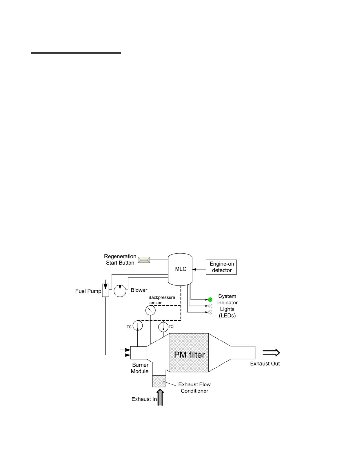
The Phoenix (Figure 1) consists of three main subsystems: the PM filter assembly, the control
system, and the regeneration system:
• The PM filter captures over 85% of the particulate matter (soot) from the diesel engine
exhaust while the equipment is operating.
• The control system monitors the Phoenix and engine during operation and controls the
regeneration cycle, which cleans out the PM filter.
• The regeneration system operates while the machine is parked, engine is off, and the
operator has started regeneration in response to the flashing amber light. The complete
regeneration cycle takes approximately 2 hours.
Figure 1: Phoenix system schematic drawing.
Phoenix_Owner's_Manual-2011-06 Page 8
Page 12
PM Filter Assembly
Attention:
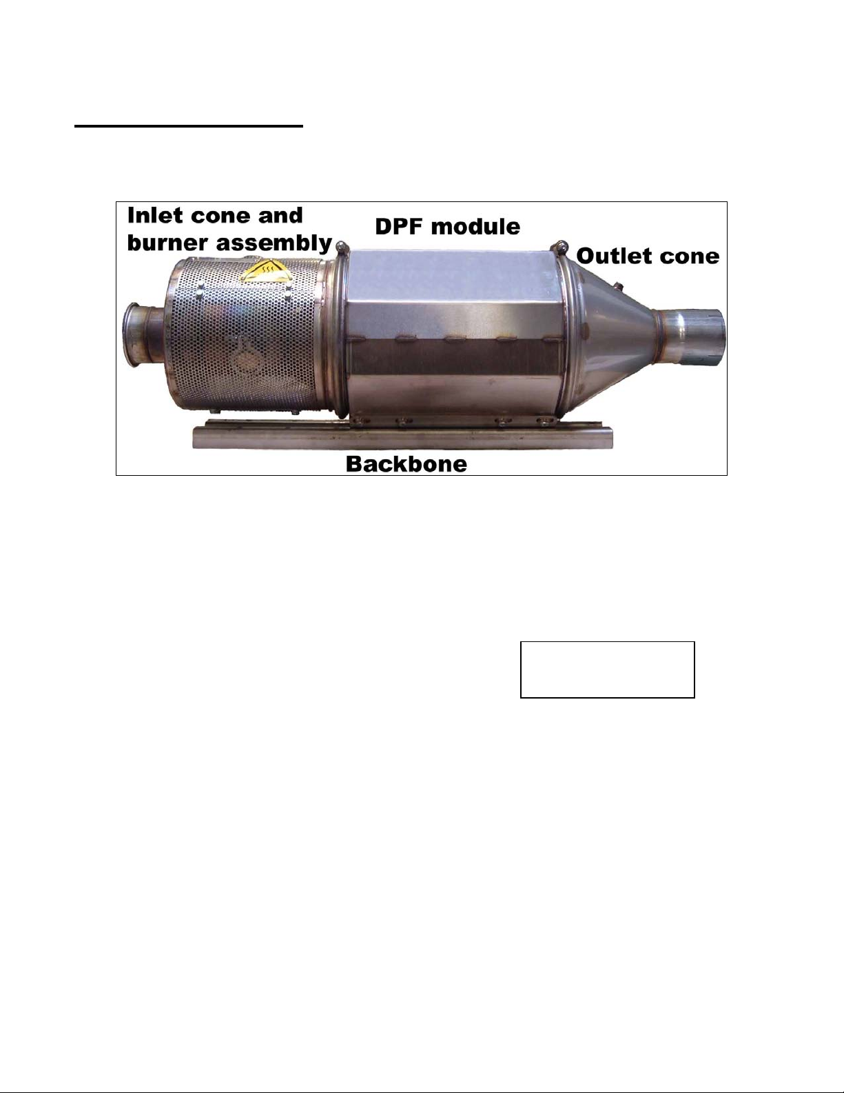
The PM filter assembly (Figure 2) is the core of the Phoenix system and it usually will replace
the muffler. The assembly has important features listed below:
Figure 2: PM Filter Assembly.
Cleaire provides a mounting assembly specifically designed for the Phoenix. Although the
PM filter assembly replaces the stock muffler, it is important to note that the PM filter
assembly is heavier than a typical muffler.
The PM filter includes ceramic materials; its care and handling require the following:
1. Do not drop or hammer.
2. Use appropriate equipment when lifting.
3. Protect from water intrusion.
4. Protect from accidental impacts.
5. Do not weld.
6. Protect flanges during transport (use the foam shipping covers).
The PM filter assembly creates backpressure on the engine
In the process of removing over 85% of the soot and ash from the exhaust, the PM filter
creates backpressure on the engine. At times, the backpressure from the PM filter (and
Phoenix system as a whole) may be higher than the backpressure caused by a muffler. The
actual amount of backpressure from the Phoenix varies instantaneously depending on the
engine speed and load and the soot and ash loading in the PM filter. The regeneration
process removes the carbonaceous part of the soot and thereby lowers the backpressure.
Handle with care!
Phoenix_Owner's_Manual-2011-06 Page 9
Page 13
Control System
The MLC and some electrical components are housed in the Controls Box. The MLC monitors
engine conditions and the Phoenix when the engine is operating. The MLC also continually
logs operating data and records instances of unusual conditions. The MLC controls the
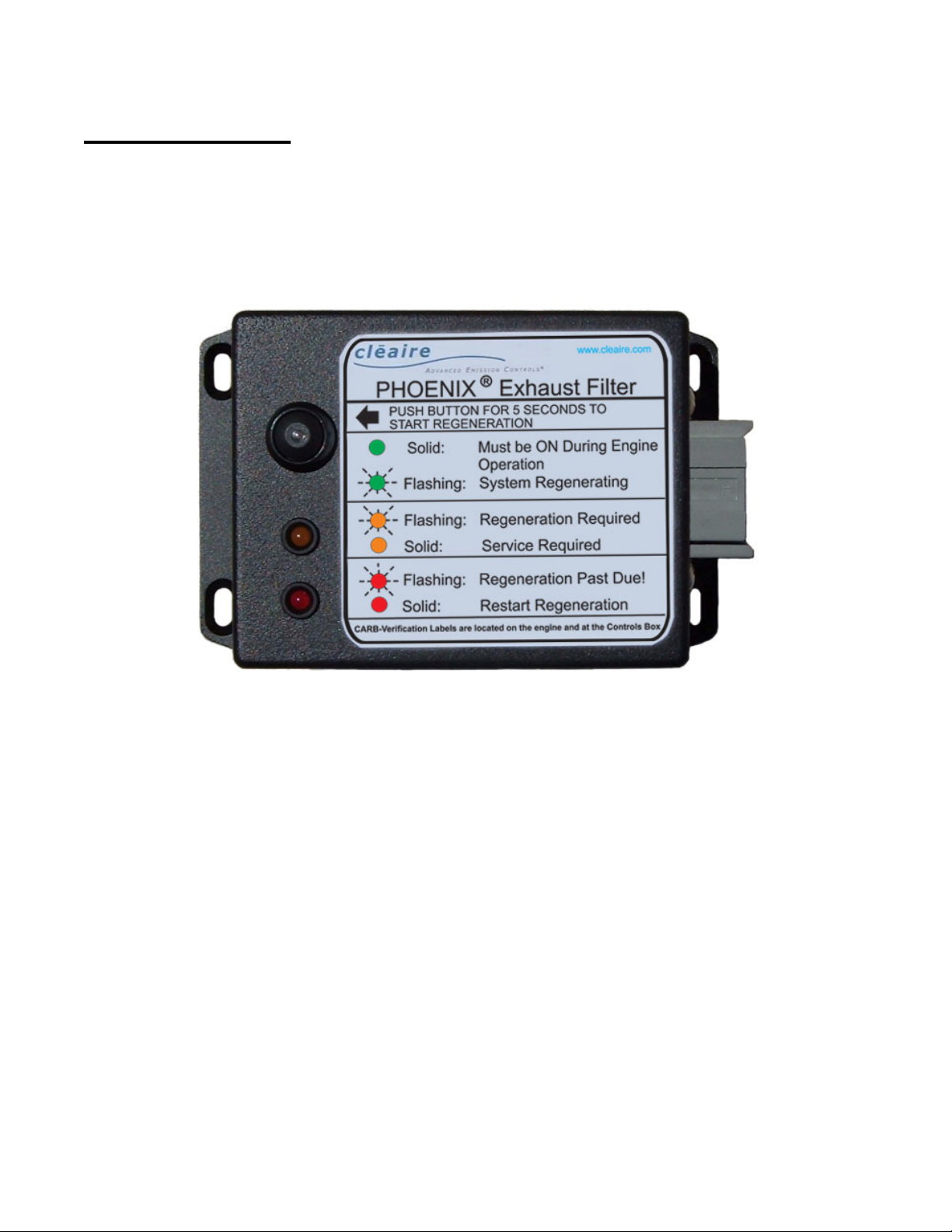
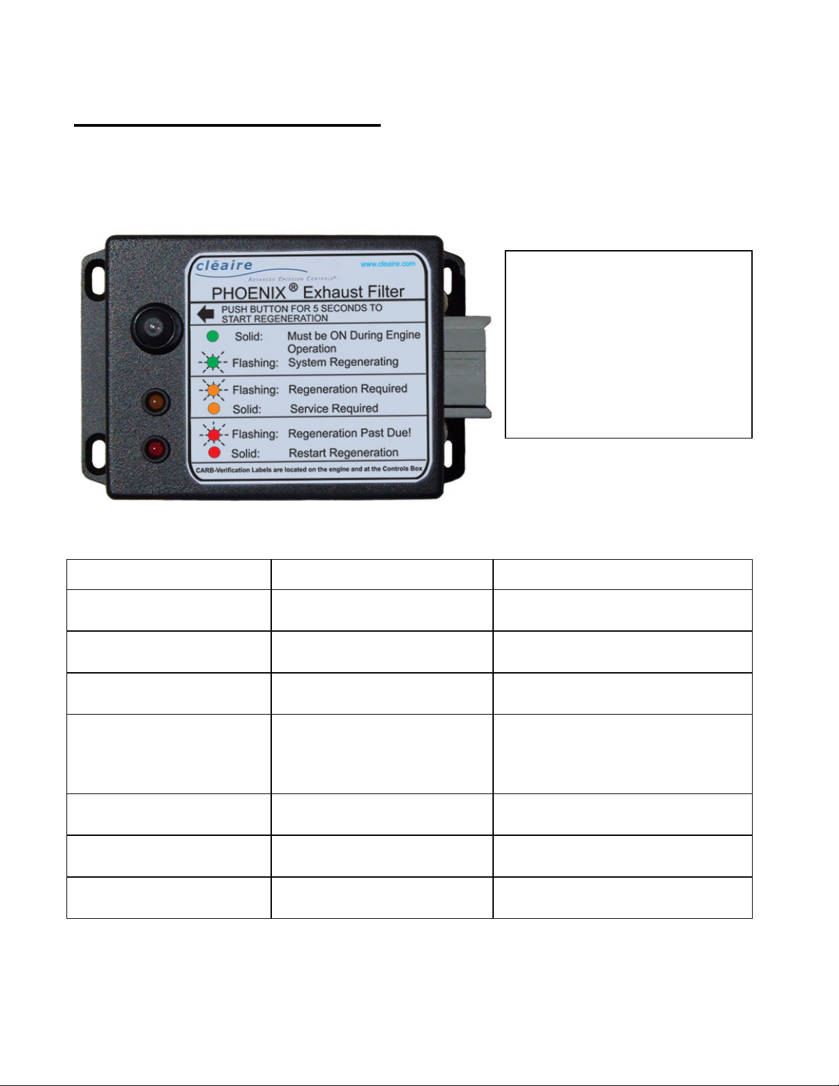
regeneration cycle and it controls the system indicator lights (see Figure 3, also referred to as
the LED’s). The MLC turns on the flashing amber light to alert the operator when regeneration
is required.
Figure 3: Operator Interface Module.
The installing dealer will have installed the Operator Interface Module in a clearly visible and
accessible location. The operator should look at the lights daily and respond accordingly: the
meaning of each light and the appropriate actions for the operator to take are described in the
“Operations” section of this manual starting on page 14.
If the operator neglects to regenerate the Phoenix, the MLC will turn on a flashing red light. At
this point, the operator may experience a loss of power from the engine. The flashing red light
indicates that the PM filter is well past due for regeneration. Further prolonged operation could
damage the emission control system and engine exhaust components. The driver or operator
should respond to a flashing red light according to the detailed explanation given in the “Red
Light – Flashing” section on page 18.
Phoenix_Owner's_Manual-2011-06 Page 10
Page 14
Regeneration System
The regeneration system cleans out the PM filter. It consists of a fuel burner module and an
air blower. Over a controlled cycle, heat and air are provided to the PM filter to oxidize the
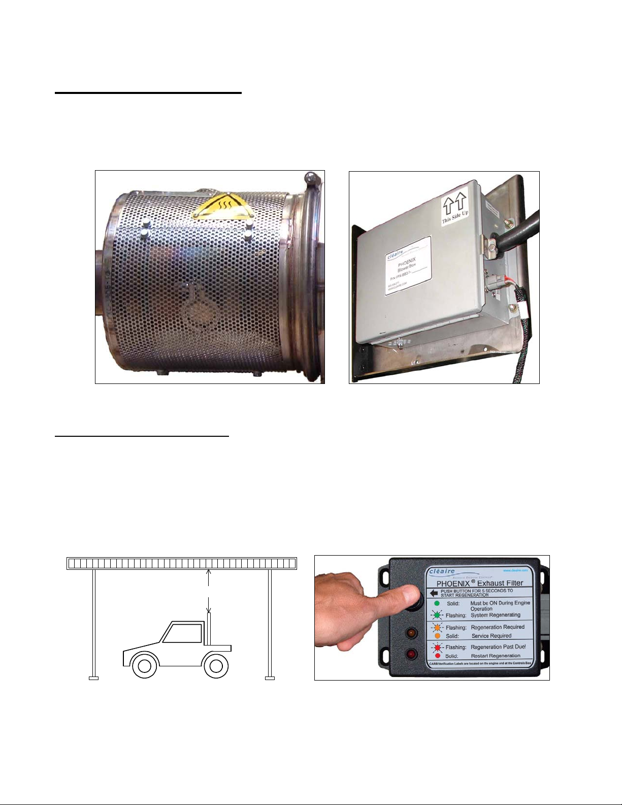
collected soot. The burner module (Figure 4) provides heat and the Blower Box (Figure 5)
provides air. The regeneration process is controlled by the MLC.
Figure 4: Burner module
Figure 5: Blower Box.
Before starting a regeneration
Before starting regeneration, the machine must be parked on level ground in a well ventilated
area far away from any combustible material and the engine must be off. Battery chargers
must not be connected during regeneration. If parked underneath an overhead structure, there
must be good air circulation and at least 18 inches of vertical clearance above the stack
(Figure 6). Also, in cold weather, Cleaire recommends starting regeneration soon after the
engine is turned off so the fuel is still warm. After the operator pushes the start button (see
Figure 7), the MLC powers the blower and ignites the burner to start the regeneration process.
Have at least 18 inches of clearance
Figure 6: If parked under an overhead
structure, have at least 18-inch clearance.
Figure 7: When the amber LED starts
flashing, push the button to regenerate.
Phoenix_Owner's_Manual-2011-06 Page 11
Page 15

Typical regeneration cycle
During regeneration, the blower moves the hot air from the burner through the PM filter
causing the collected soot to oxidize. The burner turns off after approximately 75 minutes.
The blower continues to run several minutes to cool down the burner. The PM filter will remain
hot for several hours. A complete regeneration cycle takes approximately 2 hours.
Elapsed time between regenerations
Typically, the vehicle or equipment will operate approximately 8 to 32 hours between
regeneration requests. The actual elapsed engine-on time between regenerations will depend
on many factors including engine model, maintenance condition, engine load pattern, and
operator behavior.
Regeneration-on-demand option
With the regeneration-on-demand option activated in the MLC, the operator may regenerate
the system any time they want by pushing the start button; in this case, the amber LED does
not have to be flashing in order to initiate regeneration. Operators use this feature when they
want to ensure they have a soot-free filter, such as before starting a mission-critical trip.
Whether or not to activate the regeneration-on-demand feature is the customer’s preference.
The option is not activated in the factory setting for the MLC. A trained technician using the
MLinC program can activate the regeneration-on-demand option in the MLC.
Do not start engine during regeneration; if engine is needed, do a controlled shutdown
Starting the engine before the full two hours have elapsed may damage the PM filter. If the
engine needs to be started before the regeneration has finished, then push and hold the
regeneration start button for 5 seconds. This will stop the regeneration and allow the system
to safely go through a controlled shutdown. After the system has finished the controlled
shutdown (the blower will be off), the engine may be started without damaging the PM filter.
Attention:
Damage to the PM filter caused by starting the engine during the regeneration
cycle may be the basis for denying a warranty claim.
Fuel pump may turn on and off at the start of regeneration
During the first 7 minutes of burner operation, there may be periods when the fuel pump shuts
off for a few seconds, then comes back on for a short time, then turns off again, and so on. Do
not be alarmed if you hear the fuel pump turn off for short periods of time. Similarly, you may
hear the glow plug relay click on and off repeatedly at the very start of regeneration.
If burner fails to light
If the burner fails to light, the red LED will turn on solid after a few minutes alerting the operator
to push the button again. If the burner fails to light after repeated attempts, the amber LED will
turn on solid indicating that service is required.
Phoenix_Owner's_Manual-2011-06 Page 12
Page 16
Low-Voltage Switch (Optional)
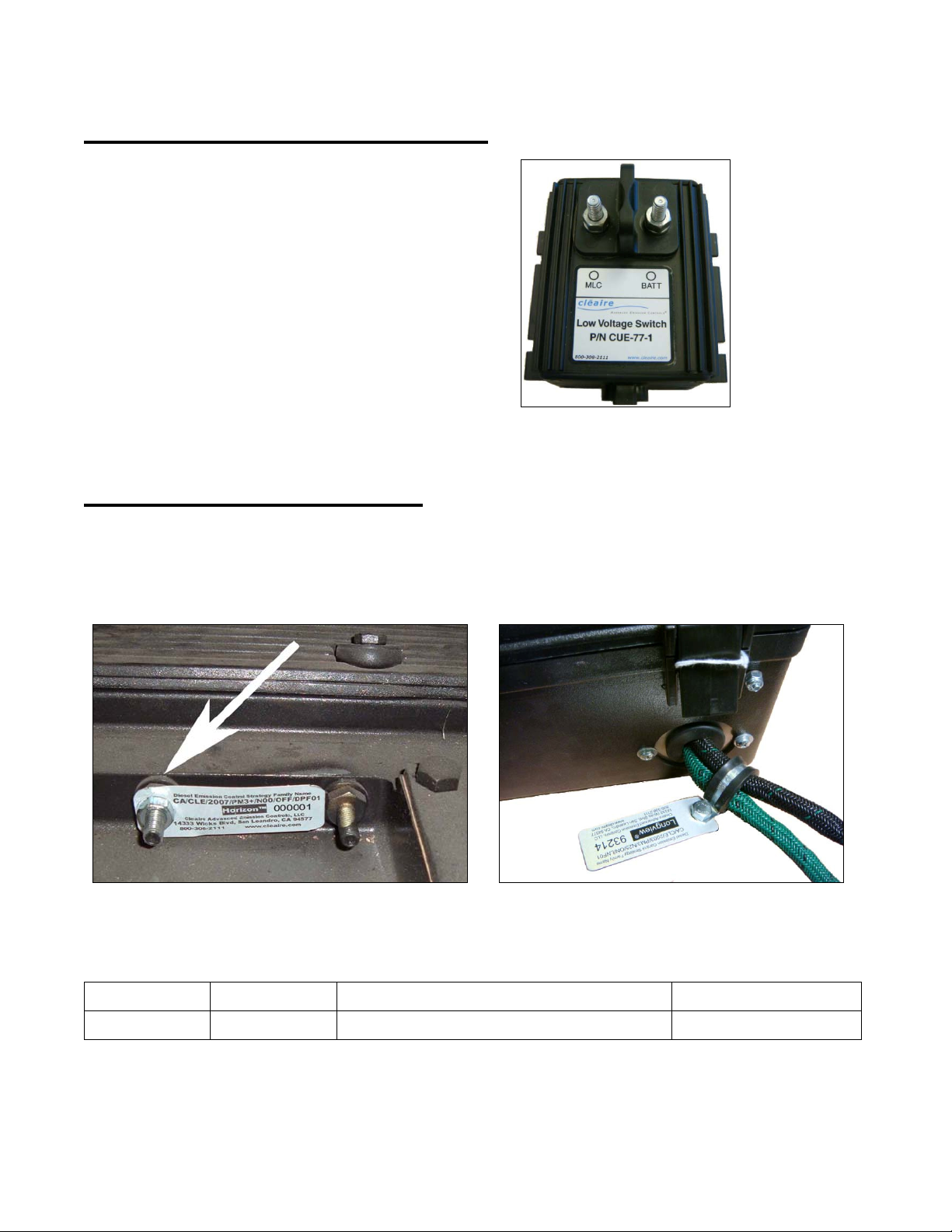
A low-voltage switch (Figure 8) is
an option for the Phoenix for
equipment that is operated
intermittently. It is designed to
disconnect power to the MLC in the
event voltage drops to a set point.
Once the engine is started, the lowvoltage switch automatically resets
and restores power to the MLC and
Phoenix system.
Figure 8: Low-voltage switch.
CARB-Verification Labels
The Phoenix is provided with two CARB-verification labels. One is installed on the engine (see
Figure 9) and the other one is attached to the wiring harness at the Phoenix’s Controls Box
(Figure 10). If either label is missing, order replacements from a Cleaire-authorized dealer. Be
sure to order the correct label for your application (see the table below the pictures).
Figure 9: Example of CARB-verification label
installed on engine.
(Example is from a Horizon system.)
Product Application Verification Family Name Label Part Number
Phoenix Off-road CA/CLE/2009/PM3+/N00/OF/DPF01 CUH-750-A
Phoenix_Owner's_Manual-2011-06 Page 13
Figure 10: CARB-verification label attached
to wiring harness at Controls Box.
(Example is from a Longview system.)
Page 17

O
PERATIONS
Phoenix_Owner's_Manual-2011-06 Page 14
Page 18

Pay Attention to the System, Engine and Equipment
The owner or operator should observe the Phoenix, engine and machine’s operation on a
regular basis. See the “Operator Interface Module” section on page 16 for a detailed
description of each light’s meaning and the appropriate response. Use the Troubleshooting
(page 25) if you suspect the engine, Phoenix are not operating properly. Contact a Cleaireauthorized dealer (or a properly trained technician under the owner’s control) when needed.
1. The operator or the owner’s technician should observe the green, amber and red lights
before starting the engine and on a daily basis.
2. During engine operation, there should not be soot emissions from the Phoenix clamps or
tailpipe. Notify a Cleaire-authorized dealer (or the owner’s technician) if any unusual
exhaust emissions are observed.
3. Periodically inspect the exhaust system for integrity. Note anything abnormal and make
repairs as warranted. For vertical exhaust stacks, make sure the turn out stack or rain
cap is in place and functioning properly. Contact a Cleaire-authorized dealer as needed.
4. Periodically inspect the Phoenix fuel system for any leaks and for integrity. Make a note of
anything abnormal and make repairs as needed. Contact a Cleaire-authorized technician
as needed.
5. Be sure the Phoenix heat shield panels are in place. If any are missing, contact a Cleaireauthorized dealer as soon as possible for service.
Regenerating the Phoenix
The regeneration system is described in detail on page 11.
1. If the amber LED is flashing, the Phoenix needs to be regenerated.
2. At the end of the shift, park the machine on level ground, and turn the engine off.
Reminders: park in a well ventilated area far from any combustible material and
battery chargers should not be connected during regeneration.
3. Push the regeneration start button and hold for 5 seconds.
Reminder: in cold weather, start the regeneration soon after the engine is turned off
so the fuel is still warm.
4. The green LED should start flashing (and will continue to flash during regeneration).
5. Do not start the engine for at least 2 hours; allow the regeneration process to finish.
Reminder: starting the engine too soon could damage the PM filter.
The green light on solid and the amber and red lights off indicate that the regeneration was
successful. In this case, you may operate the equipment normally.
If the burner failed to start, the red LED will be on solid and the operator should push the
regeneration start button again. If the burner fails to light after repeated attempts, the amber
light will turn on solid. If the amber is on solid, contact a properly trained technician for service.
Phoenix_Owner's_Manual-2011-06 Page 15
Page 19
Operator Interface Module
The operator must observe the indicator lights on the Operator Interface Module (see
Figure 11) before starting the engine and on a regular basis. The operator also must
respond as needed. Note: all the LED’s will turn on briefly when the engine is first started.
This allows a simple way for the operator to verify that all the lights are working.
The label placed next to the
lights (Figure 11) provides a
brief description of each light’s
meaning.
The light meanings are
summarized in the table below
(and are explained in greater
detail after the table).
Figure 11: Operator Interface Module.
Condition Meaning Action
1. Green LED is off
(while engine is on)
2. Green LED is on solid MLC® is on
3. Green LED flashing Regeneration is in progress
4. Amber LED flashing
5. Amber LED on solid Phoenix needs service
6. Red LED flashing
7. Red LED on solid Burner did not ignite.
Phoenix needs service
Phoenix needs to be
regenerated
Phoenix is past due for
regeneration
Contact a Cleaire-authorized
dealer for service.
No action required (unless
indicated by the other lights).
Make sure engine is off.
(Stay away from hot surfaces.)
At the end of the shift, turn the
engine off, push the regeneration
start button (and confirm that the
burner ignites).
Contact a Cleaire-authorized
dealer for service.
Follow the “Red Light – Flashing”
instructions on page 18.
Push regeneration start button
again.
Phoenix_Owner's_Manual-2011-06 Page 16
Page 20

Green Light Must Be ON While the Engine Is Operating
If the green light is off, there is likely no power to the Phoenix system. If there is a power
disconnect, low-voltage switch or circuit breaker installed, check it. Contact a Cleaireauthorized dealer for service if needed.
Green Light – Flashing
A flashing green light means regeneration is in progress and the engine must stay off.
CAUTION:
A flashing green light indicates that
the system is regenerating and the Phoenix is hot.
Amber Light – Flashing
If the amber light starts flashing, then the Phoenix needs to be regenerated at the end of the
shift. Engine must be off. The complete regeneration process takes 2 hours.
ATTENTION:
A flashing amber light means that the Phoenix needs to be regenerated
(push regeneration start button). Engine must be off.
Amber Light – On Solid
A solid amber light indicates a broken sensor, disconnected sensor or system fault. Contact a
Cleaire-authorized dealer (or a properly trained technician under the owner’s control) as soon
as practical.
ATTENTION:
A solid amber light indicates that service is required.
Verify that all the wiring harness connections are properly attached. If the amber light stays
on, have the system serviced as soon as possible. For some faults, the solid amber light can
only be turned off by connecting the service computer to the MLC and performing software
operations with the MLinC program.
The amber light will turn on solid for a few seconds after the engine starts. This allows the
operator to confirm that the LED itself is good.
Red Light – Solid
If the burner fails to ignite, the red light will turn on solid after a few minutes alerting the
operator to push the button again. If the burner fails to ignite after repeated attempts, the
amber light will turn on solid indicating that service is required before operating the engine.
In rare instances, a solid red light (with the green light off) indicates that the MLC is damaged.
Contact a Cleaire-authorized dealer (or a properly trained technician under the owner’s control)
as soon as practical.
Phoenix_Owner's_Manual-2011-06 Page 17
Page 21

Red Light – Flashing
A flashing red light alerts the operator that the Phoenix is past due for regeneration. This
condition may be caused by, but not limited to, excess diesel fuel, soot, engine lube oil,
residual ash or foreign material in the exhaust system.
ATTENTION:
A flashing red light means that the Phoenix is past due for regeneration. Warranty
coverage may be denied due to neglect.
If the red light is flashing, it could also be an indicator of another failure in the system or engine
such as a fuel injector failure. Alternatively, the flashing red light may have come on because
the operator did not respond to the amber light (flashing or solid) in a timely manner. Ignoring
the amber light (flashing or solid) to the point that the flashing red light comes on may be
grounds for denying a warranty claim.
If the red light starts flashing, failure to regenerate the Phoenix immediately may result in
engine or Phoenix damage. If not regenerated immediately, the engine, exhaust system and
Phoenix should be inspected for damage and repairs made as needed before the machine is
put back into use. Continuing to operate the engine with a flashing red light may result in
damage to the engine, exhaust system, or Phoenix and may be the basis for denying a
warranty claim.
Phoenix_Owner's_Manual-2011-06 Page 18
Page 22

Conditions That May Damage the Phoenix
The operator should be aware of conditions that could result in damage or failure of the PM
filter assembly or other parts of the system. If any of these events occur, it is the owner’s
responsibility to have the Phoenix inspected and, if necessary, repaired.
See the owner’s legal requirements under the Clean Air Act and CARB
regulations in the “Owner’s Legal Obligations” section on page 3.
Mechanical damage can occur if any system component is mishandled or accidentally
impacted. The glow plug may be damaged if a battery charger is connected during
regeneration. Internal damage to the PM filter assembly can occur from various forms of
engine failure such as losing a turbo or head gasket. These events would cause foreign debris
to enter the exhaust gas and then impact the PM filter assembly, likely causing some damage.
Furthermore, losing a turbo, a failed injector, or a major oil leak could result in excessively high
temperatures in the PM filter. If the engine loses the turbo, the driver should pull off the road
to a safe location as soon as possible and shut the engine off.
Engine oil consumption has an impact on the operation and maintenance of the Phoenix. If
engine oil consumption exceeds the engine manufacturer’s specification, the engine should be
repaired. Failure to do so may damage the Phoenix and may be the basis for denying a
warranty claim. High oil consumption will increase the rate of ash accumulation in the PM filter
and will lead to more frequent maintenance. The “Engine Oil Consumption and Lube Oil Ash”
section on page 28 explains the impacts of oil consumption and ash content on the operations
and maintenance of the system.
Power washing the equipment should not be a problem for the PM filter assembly or Phoenix
system. Avoid pointing the high-power wash at any Phoenix system components or
connectors. However, depending on the power washing technique, it may be possible to
loosen an electrical connector. If a connector comes loose, the amber LED might turn on. If
the amber light comes on, follow the procedures in the Troubleshooting (page 25).
Turn out stacks or rain caps are required on vertical stacks to avoid water intrusion. Be sure
the turn out or rain cap is in place and functioning properly. It is important that water does not
enter the exhaust pipe where it could migrate to the PM filter. Avoid low hanging branches or
other obstacles that could knock off the rain cap.
Phoenix_Owner's_Manual-2011-06 Page 19
Page 23

M
AINTENANCE AND REPAIR
Phoenix_Owner's_Manual-2011-06 Page 20
Page 24

Your Right to Maintenance Information
The Air Resources Board requires that Cleaire provide detailed maintenance information for
the diesel emission control system upon delivery to the end-user pursuant to section
2706(h)(2), Title 13, California Code of Regulations, at no additional cost to the owner. If you
do not already have this information, contact Cleaire at 1-800-308-2111.
The Importance of Engine Maintenance
Proper engine maintenance is critical for the proper functioning of your diesel emission control
strategy. Failure to document proper engine maintenance, including oil consumption records,
may be grounds for denial of a warranty claim for a failed component of a diesel emission
control strategy.
The Importance of Properly Maintaining a Diesel Emission
Control Strategy
Proper maintenance is critical for the diesel emission control strategy to function as intended.
Failure to document proper diesel emission control strategy maintenance, including cleaning
and/or ash removal of the system, replacement of consumables, and replacement of
broken/failed parts, may be grounds for denial of a warranty claim for a failed component of a
diesel emission control strategy.
Maintenance Schedule
Cleaire recommends that a Cleaire-authorized technician or a properly trained technician
under the owner’s control perform the maintenance and repair of a Phoenix. Preventative
maintenance is required once a year or every 2,000 hours (whichever comes first) to ensure
that the system is maintained in good operating condition; however, the DPF may require
cleaning more often than that depending on the engine’s oil consumption rate. See the
“Engine Oil Consumption and Lube Oil Ash” section on page 28 for more information.
The owner is legally required to keep the Phoenix in good operating condition in
order to comply with the Clean Air Act and CARB regulations (for systems
operating in California). See the “Owner’s Legal Obligations” section on page 3.
Failure to have the preventative maintenance performed may be the basis for denying a
warranty claim. Maintenance or repairs done by anyone other than a Cleaire-authorized
technician is the responsibility of the person or organization performing the work. The cost of
parts and labor for preventative maintenance are not included in the purchase price of the
Phoenix system. The parts and labor included in preventative maintenance are listed in the
“Preventative Maintenance Labor and Parts” section below.
Phoenix_Owner's_Manual-2011-06 Page 21
Page 25

Preventative Maintenance Labor and Parts
The preventative maintenance by a Cleaire-authorized technician includes:
o Inspect the Controls Box and components.
o Download data from the MLC and review the Instant Report.
o Confirm the system indicator lights are functioning properly.
o Inspect the Blower Box and components. Replace the air filter.
o Inspect the check valve and air-supply hose.
o Inspect and clean the burner module.
o Inspect the fuel metering pump and fuel filter. Replace filter if dirty. If the fuel filter is
dirty, inspect the fuel in the tank and the fuel tank pick-up filter and replace it if it is dirty.
o Test solenoid valve and clean.
o Inspect the BP sensor and sensor breather. Clean out BP tubing and ports.
o Inspect and clean the DPF.
o Inspect exhaust tubing.
o Reinstall the PM filter assembly and confirm it is properly mounted.
o Inspect the sensors and wiring harness.
o Upgrade the MLC program if necessary.
o Check CARB-verification labels.
o Make repairs (if any of the above inspections showed repairs are needed).
o Perform comprehensive tests of the system’s operations.
PM Filter Maintenance
It may be necessary to periodically clean the PM filter (in addition to the cleaning during
preventative maintenance) depending on the machine’s driving cycle and the ash content of
the diesel fuel and lube oil. The collection of inorganic ash results in an increase in
backpressure from the PM filter over time. If ash in the PM filter results in high backpressure
then the amber light will flash. If the light begins flashing soon after regeneration, then it is
likely that the PM filter has become loaded with ash and will need cleaning. Note: higher than
normal oil consumption will increase the rate of ash accumulation in the PM filter, and thus
may require more frequent maintenance.
Cleaire recommends the use of low-ash engine oils (CJ-4 oil). These products have been
specifically designed for use with a PM filter, and can significantly reduce the buildup of ash in
the PM filter and extend the filter cleaning interval. See the “Engine Oil Consumption and
Lube Oil Ash” section on page 28.
A Cleaire-authorized dealer can clean the PM filter. They also will ensure that the collected
material (ash and soot) is properly disposed in accordance with all applicable Federal, State
and local laws governing waste disposal.
Phoenix_Owner's_Manual-2011-06 Page 22
Page 26
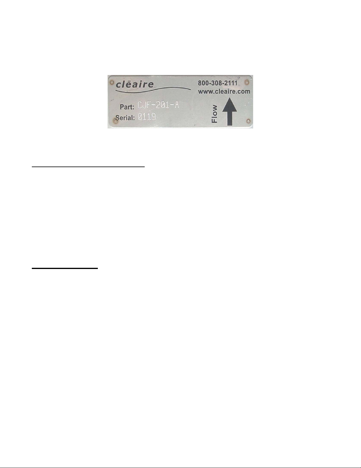
The PM filter is designed to process exhaust flow in only one direction. If the PM filter
is removed for cleaning, be sure it is reinstalled in the proper flow direction as indicated
by the arrow on the part tag (Figure 12).
Figure 12: PM Filter (DPF) part tag and flow arrow.
Exhaust Tubing and Components
All tubing connections between the engine and the PM filter assembly should be gas-tight and
leak-free. Also, all tubing between the engine and PM filter assembly must be in good
condition. This requirement includes any other components such as exhaust brakes.
Aluminized mild steel tubing or rusty tubing could flake off into the exhaust stream. If flaking
occurs, the PM filter may plug, resulting in high backpressure and engine power loss. Cleaire
recommends stainless steel tubing between the turbo and the PM filter assembly. It is the
engine owner or operator’s responsibility to ensure that all tubing in this critical area be
maintained in good condition.
Service Calls
The MLC® controls the green, amber and red indicator lights to provide system status as
described in the “Operator Interface Module” section (page 16). However, not all conditions
will be detected by the MLC® (for example, a traffic accident that physically damages the PM
filter assembly). Therefore, it is important that the owner and/or operator routinely observe the
equipment and Phoenix operations in addition to watching the indicator lights. See the
“Operations” section (page 14) for routine observations that the driver and/or owner should
perform and the “Owner’s Obligations” section on page 33.
Upon any indication of a malfunction, promptly contact a Cleaire-authorized dealer (or the
owner’s technician). See the “Contact Information” section on page 3. Please be prepared
with the following information:
1. Fault information and descriptions in as much detail as possible.
2. The data plate part number and serial number (see Figure 12).
Phoenix_Owner's_Manual-2011-06 Page 23
Page 27
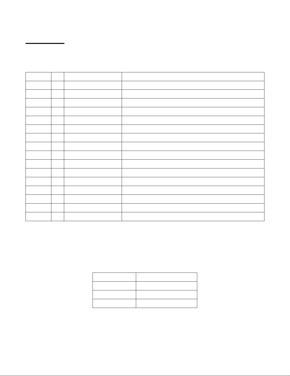
Parts List
A complete parts list was provided with the system. Contact your Cleaire-authorized dealer if
you need a replacement list. The major parts are listed in the table below.
Phoenix® System Major Parts List
Item # Qty
1
2
3
4
5
6
7
8
9
10
11
12
13
14
15
1 CJF-__ __-__ Diesel Particulate Filter Assembly, Unidirectional
1 CPXC-J__ __E-__ __-__ Assembly, cone, inlet/burner/EFC/heat shield
1 CMA-__-__ Sensor, RPM
1 CMA-5-13-__ Sensor, thermocouple
1 CMA-5-__ Sensor, thermocouple, burner
1 CMKP6.0_ MLC® (electronic control unit)
1 CUE-45 Sensor, Backpressure
1 CUE-73-__V Regeneration Air Supply Blower
1 CUH-750K Kit, label, Verification , Phoenix
1 CUE-70-__V Glow plug
1 CMA-__-__V Controls Box – Phoenix
1 CPX-BB3-__-__V Blower box
1 CPX-BB__-__ Module, operator interface w/LEDs and label
1 CPX-FPA-__-__V Fuel metering pump and filter assembly
1 CUP-74 Valve, check, air
Part Number Description
16
1 CHZ-OCJ__-__ Cone, outlet (as applicable)
Spaces represent variables depending on specific configuration and application.
Parts that may be required for preventative maintenance are not covered by the product
warranty as discussed in the “Maintenance Schedule” section on page 21 and are listed in the
table below.
Phoenix® Maintenance Parts List
Part Number Description
CUP-76 Fuel tank pick-up filter
CUP-80 Air filter
CUP-81 Fuel filter
Phoenix_Owner's_Manual-2011-06 Page 24
Page 28
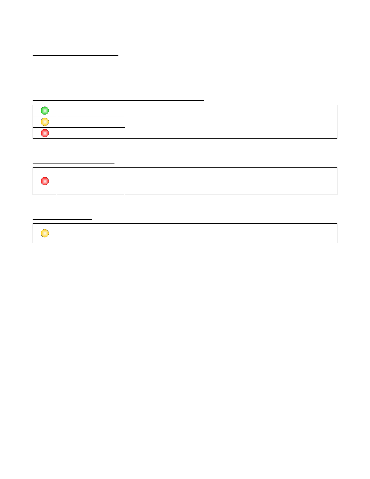
Troubleshooting
The LED’s provide some troubleshooting information. See the “Operator Interface Module”
section on page 16 for additional details. The following tables provide examples of LED
conditions and the appropriate actions to take.
Regeneration Not Finished – Burner Did Not Light
Green ON
Amber FLASHING
Red ON
Regeneration Past Due!
Red FLASHING
Service Required
Amber ON
Burner did not light. At your option, you may push the Regen
button again to attempt to restart regeneration. Call for service
if the system is not able to regenerate.
See the “Red Light – Flashing” section on page 18.
(If the red light just started flashing, regenerate immediately;
otherwise, call for service.)
Service is required if the amber is on solid
(no matter what the status is of the green or red LED’s).
Phoenix_Owner's_Manual-2011-06 Page 25
Page 29

Use the table below to diagnose and resolve potential Phoenix operating problems.
Condition Probable Cause Remedy
1. Green LED off
(while engine is on)
2. Amber LED
flashing again
soon (within a few
hours) after a
regeneration
3. Unusual exhaust
noises
4. White smoke
during startup
5. Light soot dusting
in exhaust tube
6. Visible emissions
(white or black
smoke during
normal operations)
7. Engine surges or
has power loss
• No power to MLC
• Loss of MLC program
(if amber on and green off)
• Faulty LED or wiring
• PM filter is loaded with ash
• Engine operating conditions
have changed to cause
increased soot emissions
• Loose tubing connection(s)
• Loose clamp(s)
• Crack in exhaust tube
• Crack in PM filter
• Engine turbo problem
• Normal condensation inside
the PM filter
• Normal condition • No action required.
• Engine problem resulting in
oil or coolant loss
• PM filter failure
• Normal at first start up after
regeneration or cleaning
• Engine malfunction
(most likely cause)
• Overloaded PM filter
(amber or red LED will have
been flashing for some time
if this is the cause of engine
surging or low power)
• Check fuse, wires and power source
(battery).
• Contact a Cleaire-authorized dealer
for repair.
• Try regenerating again. If the
problem persists, clean the PM filter.
• Check engine for excessive smoke
or a bad injector.
• Tighten connection(s).
• Replace damaged tube.
• Contact a Cleaire-authorized dealer
for repair.
• No action required.
• Contact a Cleaire-authorized dealer
for repair.
• None required (if only visible at first
start up after regeneration or
cleaning).
• Repair the engine.
• If the engine passes all its
diagnostic tests and regenerating
the Phoenix does not solve the low
power problem, then contact a
Cleaire dealer for service.
(PM filter will likely need cleaning.)
There is additional troubleshooting information in the Phoenix and Vista Service and
Troubleshooting Manual. This manual is for trained technicians.
Phoenix_Owner's_Manual-2011-06 Page 26
Page 30

Repair and Maintenance Clarifications
Cost
The warranty (page 35) includes a section titled “Owner’s Warranty Responsibility” which
clarifies that the owner or operator is responsible for making sure that the maintenance
described in this owner’s manual is performed. In addition to the scheduled preventative
maintenance, the amber light is another indicator that maintenance or repair is required.
ATTENTION:
A solid amber light indicates that service is required.
Cleaning the PM filter is a maintenance item and is not covered under warranty. If a repair is
required, it may be covered under the installation or product warranty depending on the cause.
The table below provides a summary of service types (maintenance or repair) and what
organization is responsible for the cost of the service.
Service Type (and subtype) Definition/Example
High backpressure from PM filter
overloaded with ash.
High backpressure from PM filter
overloaded with ash.
Clean out ash from the PM filter.
Perform multi-step complete system
check out.
System or component fails in
normal application.
System or component failed
because it was installed improperly.
System or component damaged
through abuse, neglect, or
misapplication.
Warranty period has lapsed.
Maintenance
Repair
(unplanned)
(regularly planned)
(comprehensive
preventative
maintenance)
(warrantable)
(warrantable)
(non-warrantable)
Responsibility
Owner
Owner
Owner
Cleaire
Installer
Owner
Phoenix_Owner's_Manual-2011-06 Page 27
Page 31

Engine Oil Consumption and Lube Oil Ash
Cleaire recommends that Phoenix owners monitor the oil consumption of their engines and
know the ash content of the engine oil to ensure that the PM filter is scheduled for cleaning
before it becomes overloaded with ash. This section of the manual provides information to
extend the filter cleaning interval of the PM filter.
PM filters are designed to capture all solid particles coming from the tailpipe. While most of
the captured material can be readily regenerated (oxidized) inside the filter, the PM filter will
accumulate incombustible materials, collectively called “ash,” which cannot be regenerated
and must be removed through offline cleaning.
The majority of the ash comes directly from oil consumed during engine operation, though
small amounts of ash also come from the fuel and engine wear. Most of the ash that
accumulates in PM filters is part of the lube oil additive package, and since the PM filter will
capture all solid materials coming from the engine exhaust, all the ash from oil consumption
will ultimately end up in the PM filter. Thus, the ash content of the lube oil and the oil
consumption rate become critical factors in determining the rate of ash accumulation in the
filter.
It is important to note that once the PM filter captures approximately 200 grams (about 7
ounces) of ash, it will no longer be possible to remove all the ash from the filter using existing
cleaning techniques. Therefore, it is important to proactively clean your PM filter based on 1)
oil consumption rate, and 2) lube oil ash content.
Pre-2007, CI-4 oil typically contains between 1.2 and 1.5% ash by weight. The new CJ-4 oils,
designed especially for diesel engines with PM filters, contain approximately 1.0% ash, and will
therefore result in a lower filter loading for a given amount of oil consumption. Given the ash
content, the filter must be cleaned once the engine has consumed the following amount of oil:
Every 24 Quarts with CJ-4
Every 16 Quarts with CI-4
Using the ash content of these oils, the service intervals shown in Figure 13 are recommended
to ensure optimum performance and cleanability of the PM filter.
Phoenix_Owner's_Manual-2011-06 Page 28
Page 32
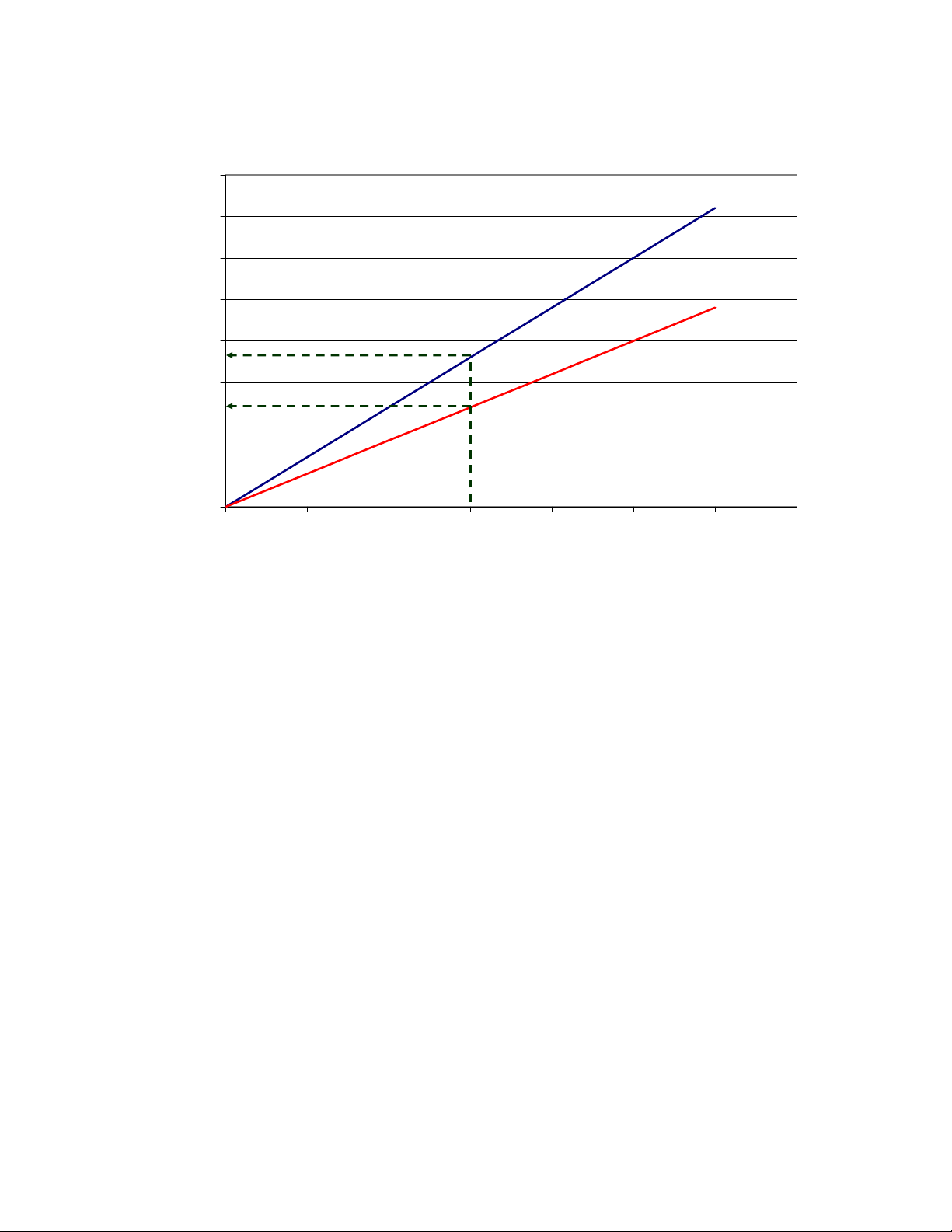
80,000
70,000
60,000
50,000
40,000
30,000
DPF Cleaning Interval for CI-4 and CJ-4 Oils
CJ-4
CI-4
CJ-4 Interval
Miles to DPF Cleaning
20,000
10,000
Figure 13: PM filter cleaning interval as a function of oil consumption rate
(The relationship is similar for oil consumption in operating hours per quart.)
CI-4 Interval
0
0 500 1,000 1,500 2,000 2,500 3,000 3,500
Oil Consumption Rate (Miles/Quart)
(for a typical well maintained engine).
The values presented above are provided as estimations and may not apply to all filters in all
applications. Factors like engine duty cycle, soot composition, ash composition and others can
also have an impact on the filter cleaning interval. Furthermore, the guide applies only to ash
accumulation in the filter; if the engine does not meet the temperature requirements for
regeneration or if there are excessive soot emissions (e.g., from a failed injector), more
frequent filter cleaning may be required to remove the soot.
Cleaire, as an industry leader in filter cleaning techniques, continues its efforts to improve its
cost-effective filter cleaning solutions. As these techniques improve, we expect to be able to
clean filters with ash loadings greater than 200 grams, thereby extending the cleaning interval
beyond the values described above.
In summary, to ensure that the PM filter is fully cleanable, Cleaire recommends that the
customer monitor their oil consumption rate and schedule filter cleaning before the filter has
accumulated 200 grams of ash. Customers can extend their filter cleaning interval by:
• Maintaining their engines to minimize oil consumption
• Switching to low ash oils
Phoenix_Owner's_Manual-2011-06 Page 29
Page 33

S
PECIFICATIONS
Phoenix_Owner's_Manual-2011-06 Page 30
Page 34

Phoenix
System
Cleaire MLC
®
Total Weight 150 pounds
Materials of Construction 304 and 316 stainless steel and
silicon carbide
Diesel Fuel Type (same as engine fuel) CARB #2 diesel, ULSD and
biodiesel up to B20
Fuel Consumption (per regeneration) 0.8 quarts
Power Consumption (avg. during regen.) 50 W
Voltage 12 V or 24V nominal
Real time clock Battery-backed
Diagnostic and Programming I/O 9-pin DBF Serial (RS-232)
(adapter from harness required)
Inputs
PM Filter Assembly Inlet Temperature Type K thermocouple, ungrounded
Burner Flame Temperature Type K thermocouple, ungrounded
Engine RPM Sensor (Frequency) 0.5 to 12 kHz
Engine Electrical Power (Battery Voltage) 12 VDC or 24 VDC nominal
PM Filter Assembly Backpressure Sensor 0 – 5 VDC
Outputs
Fuel Metering Pump (pulsed output) 12 or 24 VDC (same as input)
Power Relay 12 or 24 VDC (same as input)
Blower Speed Signal 0 – 10 VDC
Two Power Output Lines 5 VDC
Regeneration in-progress indicator Green LED flashing
Regeneration requested indicator Amber LED flashing
Phoenix system service indicator Amber LED on solid
Excessively high backpressure indicator Red LED flashing
Burner did not ignite (push button again) Red LED solid
Phoenix_Owner's_Manual-2011-06 Page 31
Page 35
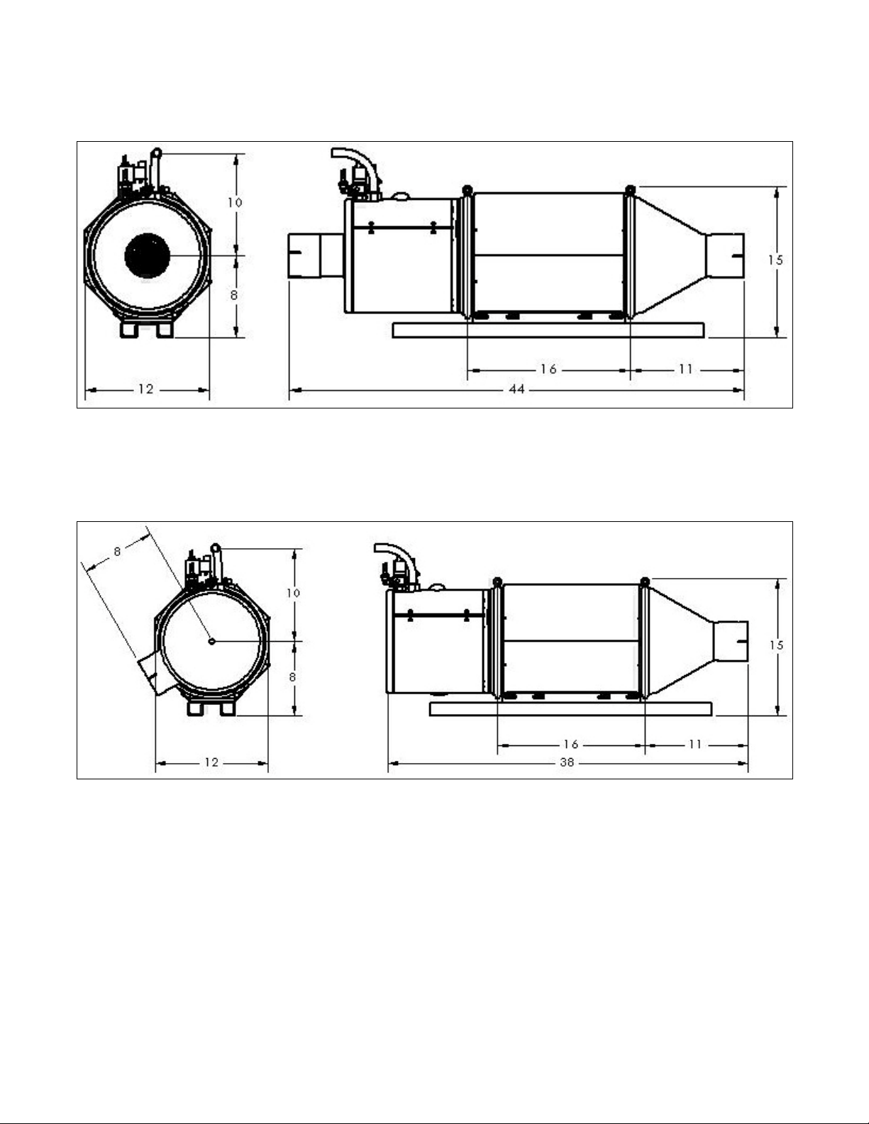
System dimensional drawings are provided in Figure 14 and Figure 15 below.
Figure 14: System dimensions (inches) with straight-in inlet cone.
Figure 15: System dimensions (inches) with side-in inlet cone.
Phoenix_Owner's_Manual-2011-06 Page 32
Page 36

O
WNER’S OBLIGATIONS
Phoenix_Owner's_Manual-2011-06 Page 33
Page 37

The owner’s actions in the table below are mandatory for proper system operation. Failure to
do the required action(s) could be the basis for denying a warranty claim or a fine by CARB.
Event or Symptom Owner’s Action Item Manual Section
Initial installation of Phoenix
system.
Flashing amber light
(Phoenix needs to be
regenerated).
Solid amber light
(bad sensor or system fault).
Flashing red light. The Phoenix is past due for regeneration.
Engine malfunction
(such as turbo failure, injector
failure, excess oil
consumption, or leaky head
gasket).
Debris or other object impacts
Phoenix system or
components.
Review this manual and know the
requirements for the Phoenix system. Keep a
copy of this manual in the equipment. Be
sure that drivers and maintenance staff
understand each item in the “Operations”
section.
At the end of the shift, park the machine on
level ground, turn off the engine, and push the
regeneration start button.
Contact a properly trained technician as soon
as practical.
Turn off the engine. If the red light just started
flashing, regenerate immediately; otherwise,
contact a properly trained technician as soon
as practical.
If the turbo fails, park in a safe place ASAP
and shut the engine off. Contact a properly
trained technician promptly.
(System components may be damaged from
foreign material.)
Contact a properly trained technician promptly
since system components may be damaged,
including hidden damage to internal
components.
This entire manual.
“Operations” (page 14).
“Regenerating the Phoenix”
(page 15).
“Operator Interface Module”
(page 16).
“Operator Interface Module”
(page 16).
“Conditions That May
Damage the Phoenix” (page
19).
“PM Filter Assembly” (page 8)
and “Conditions That May
Damage the Phoenix” (page
19).
Tubing or exhaust component
(turbo or exhaust brake, for
example) between the engine
and the PM filter assembly is
removed, replaced or in poor
condition.
For a vertical exhaust stack,
the rain cap or turn out stack
is knocked off or somehow
missing.
Oil consumption is more than
the engine manufacturer’s
specification.
Phoenix heat shield panel is
missing.
Ensure that the tubing or component is
installed properly and that no debris could
enter the exhaust stream.
(Debris or foreign matter in the exhaust
stream can damage the PM filter or system
components. Also, exhaust leaks may result
in poor system performance and safety
hazards.)
Replace the rain cap or turn out stack as soon
as practical. If any water entered the exhaust
pipe then contact a properly trained
technician.
Monitor and keep accurate records of the
engine’s oil consumption rate.
If oil consumption exceeds the specification,
repair the engine so that oil consumption is
within the manufacturer’s specification.
Contact a Cleaire-authorized dealer as soon
as possible for service.
“Exhaust Tubing and
Components” (page 23).
“PM Filter Assembly” (page 8)
and “Conditions That May
Damage the Phoenix” (page
19).
“Conditions That May
Damage the Phoenix” (page
19) and “Engine Oil
Consumption and Lube Oil
Ash” (p. 28).
“Safety Warnings” (p. 2) and
“Operations” (p. 14).
Phoenix_Owner's_Manual-2011-06 Page 34
Page 38

W
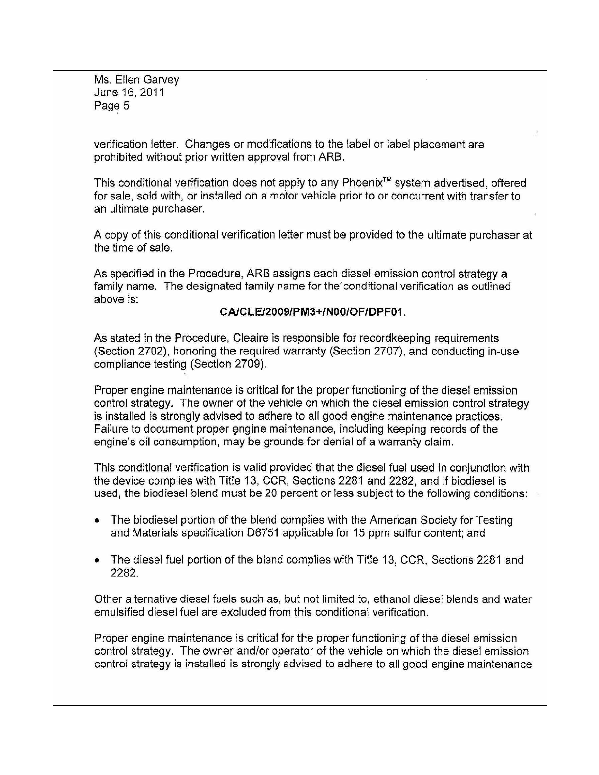
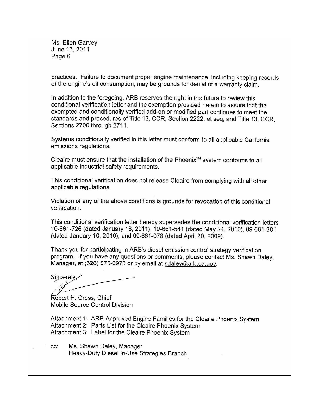
ARRANTY
Phoenix_Owner's_Manual-2011-06 Page 35
Page 39

Product Warranty
YOUR WARRANTY RIGHTS AND OBLIGATIONS
Cleaire Advanced Emission Controls (Cleaire) warrants the diesel emission control system in the application for which it is sold
or leased to be free from defects in design, materials, workmanship, or operation of the diesel emission control system which
cause the diesel emission control system to fail to conform to the emission control performance level it was verified to, or to
the requirements in the California Code of Regulations, Title 13, Sections 2700 to 2706, and 2710, for the periods of time listed
in Table 1, provided there has been no abuse, neglect, or improper maintenance of your diesel emission control system,
vehicle or equipment, as specified in the owner’s manuals. Where a warrantable condition exists, this warranty also covers
the engine from damage caused by the diesel emission control system, subject to the same exclusions for abuse, neglect or
improper maintenance of your vehicle or equipment. Please review your owner’s manual for other warranty information. Your
diesel emission control system may include a core part (e.g., particulate filter, diesel oxidation catalyst, selective catalytic
reduction converter) as well as hoses, connectors, a back pressure monitor (if applicable), and other emission-related
assemblies. Where a warrantable condition exists, Cleaire will repair or replace your diesel emission control system at no cost
to you including diagnosis, parts, and labor.
Table 1: Warranty Period
Engine Type Engine Size
Warranty Period
Light heavy-duty, 70 to 170 hp, Gross Vehicle Weight Rating (GVWR) less
than 19,500 lbs.
5 years or
On-Road
Medium heavy-duty, 170 to 250 hp, GVWR from 19,500 lbs. to 33,000 lbs.
Heavy heavy-duty, exceeds 250 hp, GVWR exceeds 33,000 lbs.
150,000 miles
Heavy heavy-duty, exceeds 250 hp, GVWR exceeds 33,000 lbs., and the
truck is:
1. Typically driven over 100,000 miles per year, and
2 years,
unlimited miles
2. Has less than 300,000 miles on the odometer at the time of installation.
Off-Road
(includes
Under 25 hp, and for constant speed engines rated under 50 hp with rated
speeds greater than or equal to 3,000 rpm
3 years or
1,600 hours
portable
engines),
Stationary,
At or above 25 hp and under 50 hp
4 years or
2,600 hours
Marine,
Locomotives,
TRU and
At or above 50 hp
5 years or
4,200 hours
APU
WARRANTY COVERAGE
For an engine used in an application listed in Table 1, the warranty period will be the years or hours or miles of operation
shown in Table 1, whichever occurs first. If any emission-related part of your diesel emission control system is defective in
design, materials, workmanship, or operation of the diesel emission control system thus causing the diesel emission control
system to fail to conform to the emission control performance level it was verified to, or to the requirements in the California
Code of Regulations, Title 13, Sections 2700 to 2706, and 2710, within the warranty period, as defined above, Cleaire will
repair or replace the diesel emission control system, including parts and labor.
In addition, Cleaire will replace or repair the engine components to the condition they were in prior to the failure, including
parts and labor, for damage to the engine proximately caused by the verified diesel emission control strategy. This also
includes those relevant diagnostic expenses in the case in which a warranty claim is valid. Cleaire may, at its option, instead
pay the fair market value of the engine prior to the time the failure occurs.
Phoenix_Owner's_Manual-2011-06 Page 36
Page 40

OWNER’S WARRANTY RESPONSIBILITY
As the vehicle, engine, or equipment owner, you are responsible for performing the required maintenance described in your
owner’s manual. Cleaire recommends that you retain all maintenance records and receipts for maintenance expenses for your
vehicle, engine, or equipment, and diesel emission control system. If you do not keep your receipts or fail to perform all
scheduled maintenance, Cleaire may have grounds to deny warranty coverage. You are responsible for presenting your
vehicle, equipment, or engine, and diesel emission control system to a Cleaire dealer as soon as a problem is detected. The
warranty repair or replacement should be completed in a reasonable amount of time, not to exceed 30 days. If a replacement
is needed, this may be extended to 90 days should a replacement not be available, but must be performed as soon as a
replacement becomes available.
If you have questions regarding your warranty rights and responsibilities, you should contact Cleaire at 1-800-308-2111 or the
California Air Resources Board at 9528 Telstar Avenue, El Monte, California 91731, or (800) 363-7664, or electronic mail:
[email protected].
Installation Warranty
YOUR WARRANTY RIGHTS AND OBLIGATIONS
The installer must warrant that the installation of a diesel emission control system is free from defects in workmanship or
materials which cause the diesel emission control system to fail to conform to the emission control performance level it was
verified to, or to the requirements in the California Code of Regulations, Title 13, Sections 2700 to 2706. The warranty period
and the extent of the warranty coverage provided by the installer must be the same as the warranty provided by Cleaire, and
the same exclusions apply.
OWNER’S WARRANTY RESPONSIBILITY
As the vehicle, engine, or equipment owner, you are responsible for presenting your vehicle, engine, or equipment, and diesel
emission control system to the installer as soon as a problem with the installation is detected.
If you have questions regarding your warranty rights and responsibilities, you should contact the installer or Cleaire at 1-800308-2111 or the California Air Resources Board at 9528 Telstar Avenue, El Monte, California 91731, or (800) 363-7664, or
electronic mail: [email protected].
Cleaire Warranty Clarifications
(Which do not limit or modify the provisions of the Product Warranty or Installation Warranty in any way)
The product warranty above is the sole warranty made by Cleaire Advanced Emission Controls, LLC. There are no other
warranties, expressed or implied, of merchantability or fitness for a particular purpose.
For the purpose of the product warranty and installation warranty, abuse or neglect includes vehicle accidents, ignoring the
system indicator lights, blending lubricating oil with fuel, or any engine failure or condition that are not proximately caused by
the diesel emission control system that allows excess lubricating oil, coolant, contaminants or debris to enter the exhaust
system. The owner shall not use any fuel additive or lube oil additive that is not approved by EPA or CARB for use in diesel
engines equipped with catalytic mufflers.
Cleaire recommends that the verified diesel emissions control strategy be installed and serviced by Cleaire authorized
personnel. Improper installation or service by unauthorized or untrained personnel may result in a denial of coverage under
the product warranty or installation warranty.
Phoenix_Owner's_Manual-2011-06 Page 37
Page 41

CARB E
XECUTIVE ORDER FOR THE PHOENIX
Phoenix_Owner's_Manual-2011-06 Page 38
Page 42
Phoenix_Owner's_Manual-2011-06 Page 39
Page 43
Phoenix_Owner's_Manual-2011-06 Page 40
Page 44
Phoenix_Owner's_Manual-2011-06 Page 41
Page 45
Phoenix_Owner's_Manual-2011-06 Page 42
Page 46
Phoenix_Owner's_Manual-2011-06 Page 43
Page 47
Phoenix_Owner's_Manual-2011-06 Page 44
Page 48

Cleaire Advanced Emission Controls, LLC
14333 Wicks Blvd.
San Leandro, CA 94577-6719
1-800-308-2111
Phoenix_Owner's_Manual-2011-06 Page 45
 Loading...