

Page 1
5
PIN SCAN
•
Unpacking
Open the box, remove the projector
from the packing and place it on a
flat, horizontal surface.
Unpack the standard accessories
supplied with the fixture. Inspect the
lamp change label (
1) and replace it
with one of the optional language
versions if necessary.
Make sure that the label is never
removed, as it displays important
safety information.
•
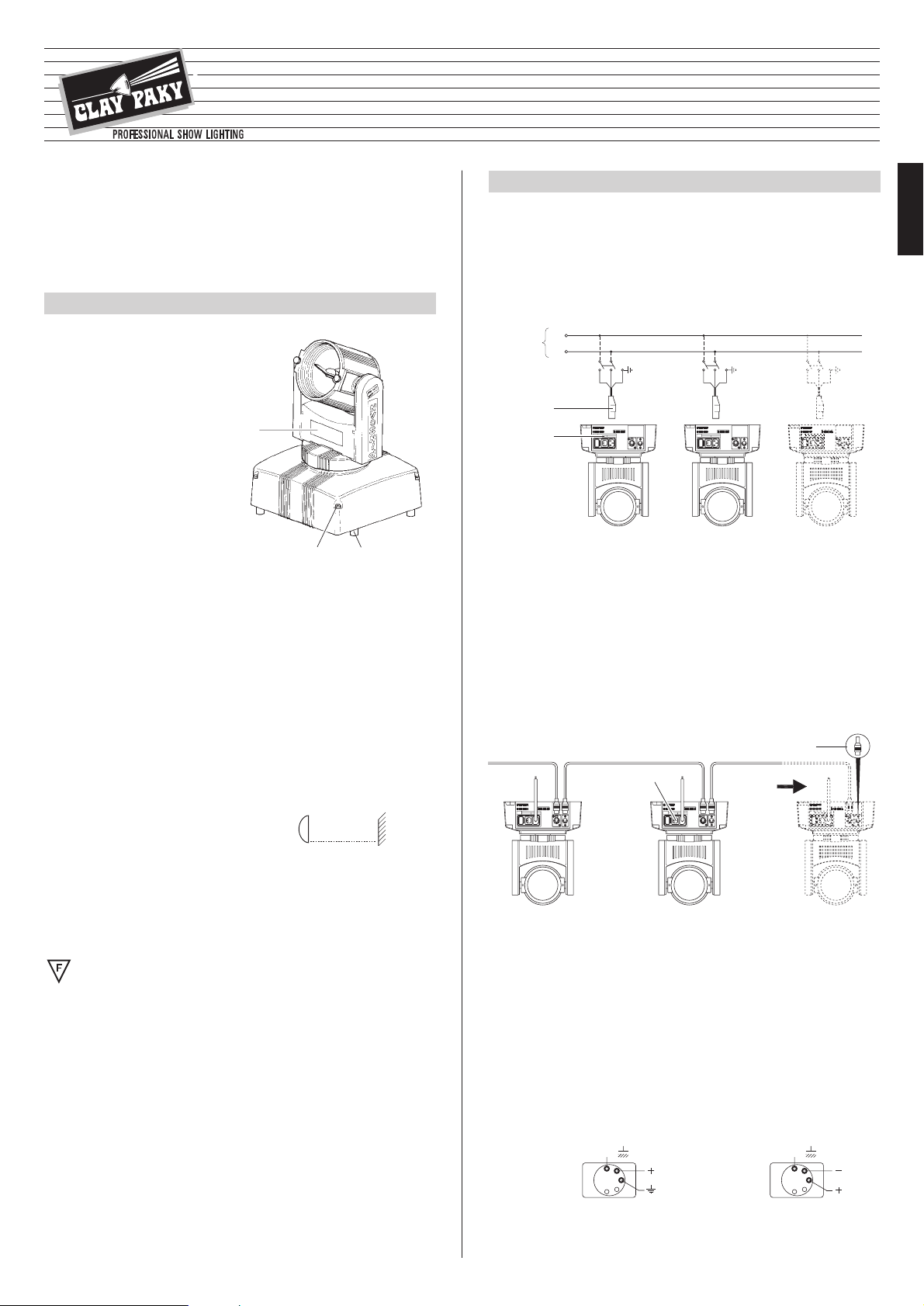
Connecting to the electrical power supply
The operations described in this heading must be carried out by a licensed electrician.
The projector must be wired up to the electrical power supply using the special socket
connector provided (
4).
It is good policy to connect projectors to the power supply by way of dedicated
switches, so that each can be turned on and off individually from a remote station.
The projector is designed to operate at the voltage and frequency indicated on the
electrical data plate (
5). Check that these two values correspond to the mains voltage
and frequency.
IMPORTANT: the projector must be connected to a power supply circuit
having a proper earth system (Class I appliance).
• Connecting the control signals
RS 232/423(PMX) - DMX 512
•
Fitting the lamp
Refer to the directions for replacement of the lamp given under heading 4 MAINTENANCE.
•
Installing the projector
The projector can be placed on the floor on the rubber feet (2) or installed on the ceiling or wall using the holes (
3) in the base.
Make certain that the anchorage is stable before positioning the projector.
•
Minimum distance from target objects
The projector must be positioned in such a way that
objects struck by the beam are located at least 1.3
m (4’ 3”) from the lens.
•
Minimum distance of inflammable materials from any part of the fixture:
m 0.1 (4”).
The fixture may be mounted on surfaces rated normally inflammable.
IMPORTANT: For better and more reliable operation of the fixture, the ambient
temperature must not exceed 35° C (95° F). Protection factor IP 20: the fixture is
protected against penetration of solid bodies more than 12mm (0.5”) in diameter (first
digit 2), but can be damaged by spray, jet, drip or rain water (second digit 0).
23
1
POWER SUPPLY AND INTERFACE
2
Projectors are wired up to the controller and one to the next using two-core
screened cable and Cannon 5 pin XLR type plug/socket connectors.
To connect a DMX line, a terminating plug (
8) with a 100Ω resistor wired between
pins 2 and 3 must be fitted to the last projector connected in series; the plug is not
required when using an RS232/423(PMX) signal.
ENGLISH
INSTALLING THE PROJECTOR
1
IMPORTANT: Read carefully. It is essential for the correct and safe use of the
equipment that erectors and operators should be fully conversant with the
information and instructions given in this manual.
INSTRUCTION MANUAL
ENGLISH
7
6
4
5
Mains
®
The wires must not come into contact with each other or with the metal
casing of the plug.
The casing of the plug/socket must be connected to the screen and to pin 1
of the connectors.
Having completed the operations described above, press the on/off switch (7).
Check that the lamp comes on and the auto-reset sequence starts.
SIGNAL
SCREEN
SIGNAL
54
3
2
1
DMX 512
SIGNAL
SCREEN
SIGNAL
RS232/423 (PMX)
1
2
3
45
12Vmax 100W
L
N
(4’ 3”)
1.3 m
12V - 100W
Page 2
6
1
DIMMER / STOPPER / STROBE
2
PA N
3
TILT
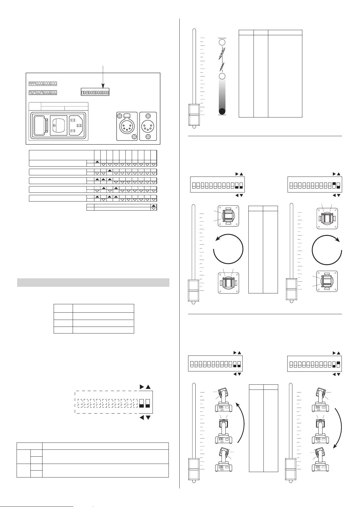
CHANNEL FUNCTIONS AND OPTIONS
3
•
Projector address codes
A single PIN SCAN projector utilizes 3 control channels. To ensure that the different
projectors are addressed correctly by the controller, a code must be assigned to
each one.The operation is carried out on each PIN SCAN by setting the microswitches as indicated in the table below.
DIGITAL START ADDRESS AND OPTIONS SELECT
Projector 1
- Channels 1-3
124
8
163264
128
256
TEST
OFF
ON
CODE
Projector
2 - Channels 4-6
OFF
ON
Projector
3 - Channels 7-9
ON
OFF
Projector
4 - Channels 10-12
ON
OFF
Projector
5 - Channels 13-15
ON
OFF
OFF
ON
Setting the TEST switch to the ON position for a few seconds with the projector
powered-up, an auto-reset routine is carried out. Leaving the TEST switch at the
ON position for a longer period, a full self-test program will be completed; once the
operation has terminated, return the switch to the OFF position.
CHANNEL
FUNCTION
ON
Pan direction change.
OFF
ON
Tilt direction change
OFF
11
12
OPTION FUNCTION
TEST
256
128
64
32
16
8
4
2
1
ON
10987654321 11 1 2
PAN
TILT
OPTIONS
Select the options by setting the microswitches as indicated.
Spotlight selection
0
1
2
3
4
5
6
7
8
9
10
BIT % EFFETTO
244 - 255 95.5 - 100
APERTO
140 54.7
STROBO LENTO
APERTO
0 0.0
CHIUSO
243 95.0
STROBO VELOCE
128 - 139 50.0 - 54.2
• DIMMER / STOPPER / STROBE - channel 1
0
1
2
3
4
5
6
7
8
9
10
BIT %
2550100
0.0
• PAN - channel 2
Operation with option 11 OFF Operation with option 11 ON
TEST
256
128
643216
842
1
ON
10987654321
11 12
PAN
TILT
0
1
2
3
4
5
6
7
8
9
10
TEST
256
128
643216
842
1
ON
10987654321
11 12
PAN
TILT
0
1
2
3
4
5
6
7
8
9
10
BIT %
255
128
0
100
50.0
0.0
• TILT - channel 3
Operation with option 12 OFF Operation with option 12 ON
TEST
256
128
643216
842
1
ON
10987654321
11 12
PAN
TILT
0
1
2
3
4
5
6
7
8
9
10
TEST
256
128
643216
842
1
ON
10987654321
11 12
PAN
TILT
Page 3

7
• Changing fuses
To change the fuses, press the tab (8) and
pull out the fuse holder (
10). Replace any
blown fuse with one of the same type and
rating as indicated on the label (
10)
attached to the holder (
9). Insert the fuse
holder and push in to engage the tab (
8).
• Routine cleaning
To maintain the light output of the projector undiminished, parts that tend to accumulate dust and grease must be cleaned periodically.
To remove dirt from the reflector and filter use a soft cloth moistened with any liquid
detergent suitable for cleaning glass.
CAUTION: Do not use solvents or alcohol
IMPORTANT: isolate the projector from the electrical power supply before
commencing maintenance work of any description.
The maximum temperature on the outer surface of the projector under normal
operating conditions is 100°C (212° F).
After switching off, do not remove any part of the projector for at least 10 minutes; once
this time has elapsed, the risk of a lamp exploding is practically zero.If the lamp needs
changing, wait a further 15 minutes to avoid the risk of burns.
MAINTENANCE
4
ENGLISH
CAUTION:
- When fitting a new lamp read the manufacturer's instructions carefully.
- The lamp must always be changed without delay if damaged or deformed by heat.
•
Only use 12V halogen lamps with a maximum power of 100W made
with low pressure technology.
8
9
10
TROUBLESHOOTING
5
No electrical power supply.
Check that power is available at
the mains socket and/or that fuses
are intact.
PROJECTOR DOES NOT LIGHT UP
FAULTS
PROJECTION FAULTY
REDUCED BRIGHTNESS
POSSIBLE CAUSES CHECKS AND REMEDIES
•
•
••
•
Lamp expended or faulty.
Change lamp (see instructions).
Deposit of dust or grease.
Clean (see instructions).
Cooling
Forced ventilation cooling system using
axial flow fan.
Housing
•
Extruded die-cast aluminium.
• Epoxy powder coated finish.
Operating position
Will function in any position.
Weight and dimensions
Weight: 5.8 kg (12 lbs 12 ozs).
Power supply
•
100-120V 50/60Hz
• 200-240V 50/60Hz
Lamps
•
12V 90W (Halostar).
To be used with special Clay Paky
pencil beam parabola (2.5°).
• 12V/50-75-100W (Halospot).
Built-in reflector with different beam
apertures.
Power consumption
150VA max. (consumption varies in
relation to the lamp).
Channels
N. 3 control channels.
Inputs
•
RS232/423(PMX)
• DMX512
Moving body
•
Movement generated by two
microstepping motors with full microprocessor control.
• Range of adjustment:
- PAN = 360°
- TILT = 227°
• Resolution:
- PAN = ± 1.41°
- TILT = ± 0.89°
TECHNICAL DATA
6
(9.1”)
230
(9.1”)
230
(3.4”)
86
(12.8”)
max 325
(7.5”)
190
1
1
2
3
4
5
3
1
2
• Changing the lamp: type HALOSTAR 12V max 100W with G 6.35 fitting
• Changing the lamp: type HALOSPOT 12V max 100W with G 53 fitting
FUSE
5 x 20
1A T
250 V
 Loading...