

Page 1
7
•
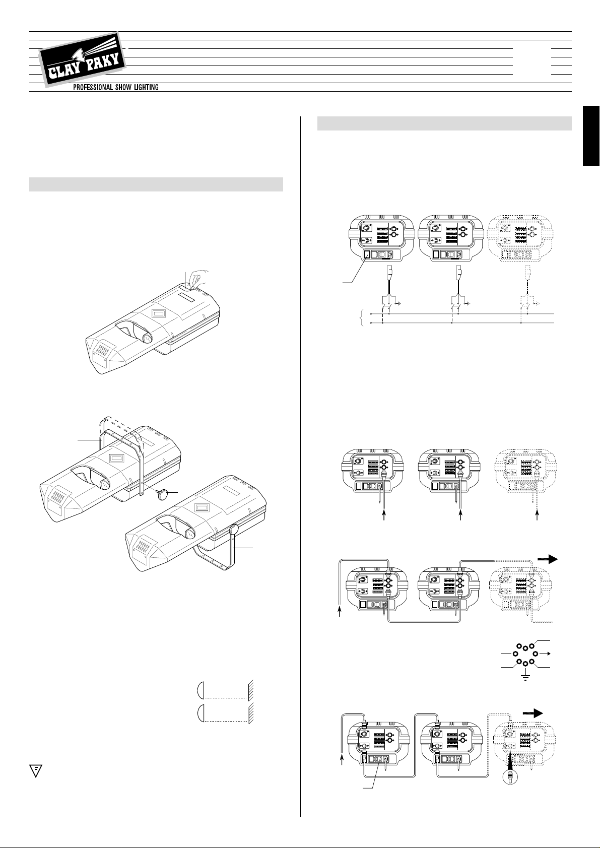
Connecting the control signals
0-10V CONNECTION
- Projectors operating independently of one another
- Projectors operating simultaneously and identically
RS 232/423(PMX) - DMX 512 CONNECTION
Projectors are wired up to the controller and one to the next using two-core screened
cable and Cannon 5 pin XLR type plug/socket connectors.
•
Connecting to the electrical power supply
The operations described in this heading must be carried out by a licensed electrician.
The projector must be wired up to the electrical power supply using the special
socket connector provided. It is good policy to connect projectors to the power
supply by way of dedicated switches, so that each can be turned on and off individually from a remote station.
The projector is designed to operate at the voltage and frequency indicated on the
electrical data plate (4) affixed to the rear end. Check that these two values correspond to the mains voltage and frequency.
IMPORT ANT: the projector must be connected to a po wer suppl y circuit ha ving
a proper earth system (Class I appliance).
IMPORTANT: For better and more reliable operation of the projector, the ambient
temperature must not exceed 35° C (95° F). Protection factor IP 20: the appliance is
protected against penetration of solid bodies more than 12mm (0.5”) in diameter (first
digit 2), but can be damaged by spray, jet, drip or rain water (second digit 0).
DMX 512
RS 232/423
ENGLISH
0 - 10V 0 - 10V 0 - 10V
0 - 10V
8
Is
PAN
GOBO
COL
TILT
7
6
31
5
2
4
•
Initial assembly operations
Position the bracket (2) the desired height and secure by tightening the knobs (3).
The bracket can also be fitted from the underside of the projector.
•
Minimum distance from target objects
The projector must be positioned in such a way
that objects struck by the beam are separated
from the lens at least by the distance indicated on
the lamp change label next to the symbol illustrated alongside.
•
Minimum distance of inflammable materials from any part of the equip-
ment: 0.10 m (4”).
The appliance may be mounted on surfaces rated normally inflammable.
•
Fitting the lamp
Refer to directions for replacement of the lamp given under heading 6 MAINTENANCE.
•
Installing the projector
The projector can be mounted in any position without its operating characteristics
being affected.
IMPORTANT: fix the projector in the desired position utilizing the holes in the bracket (2). Secure preferably using two ø10 bolts with nuts and lock washers.
Make certain that the anchorage is stable before positioning the projector.
INST ALLING THE PROJECTOR
1
POWER SUPPLY AND INTERFACE
2
•
Unpacking
Open the box, remove the projector from the packing and place it on a flat horizontal surface. Unpack the standard accessories supplied with the equipment.
Inspect the lamp change label (1) and replace with one of the optional language
versions if necessary.
Make certain that the label is never removed, as it displays important safety
information.
1
2
3
2
The connection between controller and projector must be made using a multicore cable with 8
wires of 0.25mm
2
section and a DIN 8 PIN 45°
plug/socket connector.
5
IMPORTANT: Read carefully. It is essential for the correct and safe use of the
equipment that erectors and operators should be fully conversant with the
information and instructions given in this manual.
INSTRUCTION MANUAL
ENGLISH
4
Mains
HMD 300
HTI 300
HTI 150
®
MINISCAN
L
N
(
3’ 3”
1.0 m
(
1’ 8”
0.5 m
)
)
HMD 300
HTI 300
HTI 150
Page 2
8
TEST
256
128643216842
1
ON
10987654321
1112
PAN
TILT
TILT
GOBOPAN
COL
Is
THE DIGITAL START
ADDRESS IS THE SUM
OF THE NUMBERS
PRODUCED BY THE
SELECTED SWITCHES
DIGITAL
START
ADDRESS
AND
OPTIONS
SELECT
EG.
RESPOND
C.1 - 4
EG.
RESPOND
C.17 - 20
RUN TEST
SEQUENCE
DMX 512
RS232/423
: 1 = ,2 = SIG - ,3 = SIG +
: 1 = ,2 = SIG ,3 = SIG
DIGITAL INPUT
ANALOGUE
INPUTS 0 - 10V
Projector
1-4
5-8
ON
OFF
ON
OFF
TEST
256
128
64
32
16
842
1
OFF
ON
OFF
ON
OFF
ON
OFF
ON
OFF
ON
OFF
ON
OFF
ON
OFF
ON
OFF
ON
1
2
3
9-12
4 13-16
5 17-20
6 21-24
7 25-28
8 29-32
9 33-36
10 37-40
CODE
- Channels
Projector - Channels
Projector - Channels
Projector - Channels
Projector - Channels
Projector - Channels
Projector - Channels
Projector - Channels
Projector - Channels
Projector - Channels
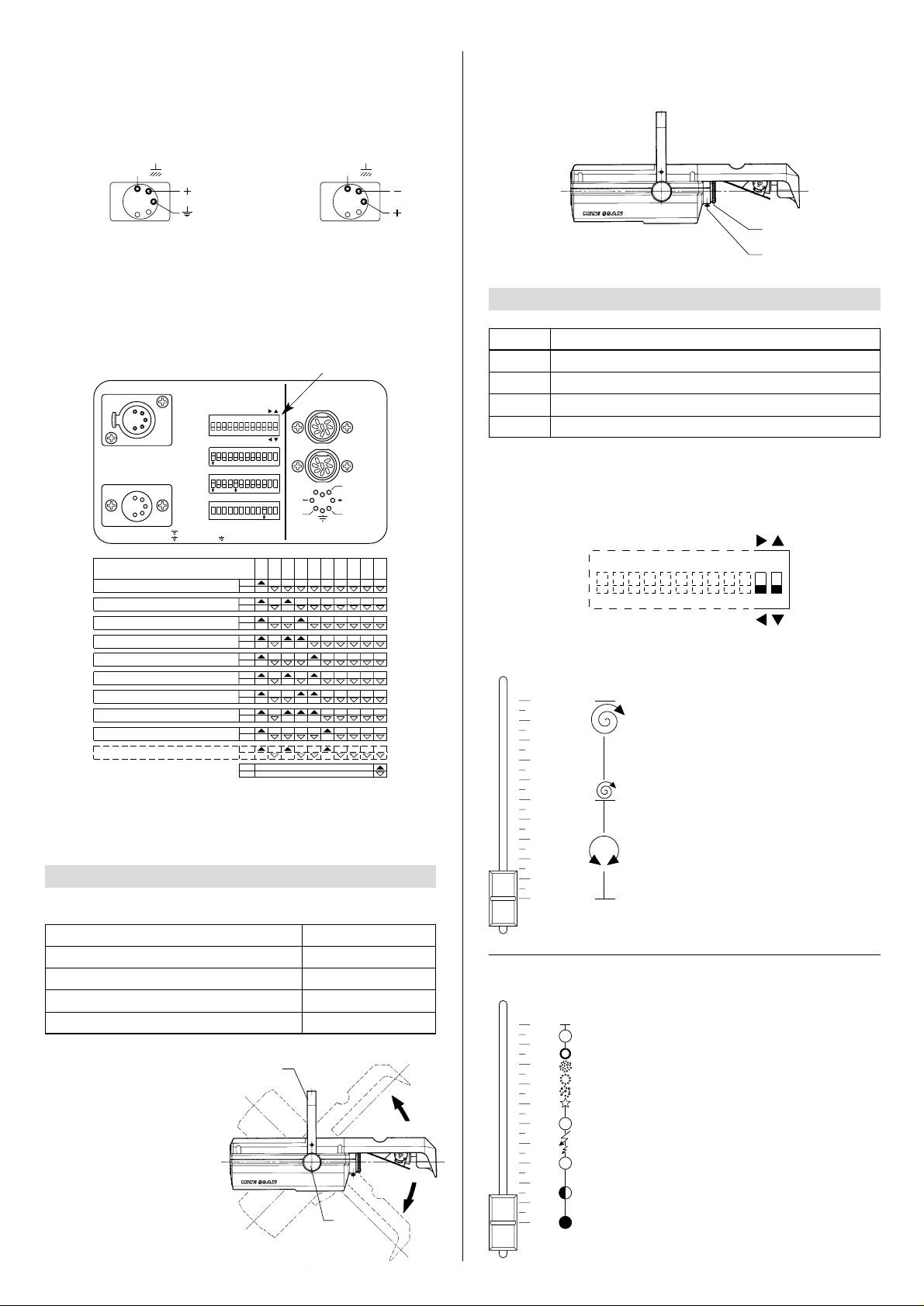
•
Aligning the beam
Having completed all the operations
indicated thus far, loosen the knobs
(3), manoeuvre the projector on
the bracket (2) until the beam is
directed at centre stage, then
retighten the knobs (3).
•
Projector address codes (for digital signals)
A single MINISCAN utilizes 4 control channels. To ensure that the different projectors are addressed correctly by the controller, a code must be assigned to each one .
The operation is carried out on each MINISCAN by setting the dip-switches as
indicated in the table below.
Before positioning the projector, set the channels as shown in the following table:
•
Adjusting the lens
Move the lens (6) back and forw ard until the projected image is satisf actorily f ocused,
then tighten the knob (7).
Projector selection
CHANNEL FUNCTIONS AND OPTIONS
4
Select the options by setting the dip-switches as indicated.
POSITIONING THE PROJECTOR
3
CHANNEL
1 COLOUR WHEEL
2
GOBO CHANGE/DIMMER/STOPPER/STROBE
3 PAN
4 TILT
POSITION OF SLIDER
0% (white beam)
100% (white beam)
50% (Central position)
50% (Central position)
CHANNEL
1
2
3
4
FUNCTION
COLOUR WHEEL
GOBO CHANGE/DIMMER/STOPPER/STROBE
PAN
TILT
TEST
256
128
64
32
16
8
4
2
1
ON
10987654321 11 12
PAN
TILT
OPTIONS
T o connect a DMX line , a terminating plug (7) with a 100Ωresistor wired between pins
2 and 3 must be fitted to the last projector connected in series;the plug is not required
when using a RS232/423(PMX) signal.
The wires must not come into contact with each other or with the metal casing of the plug.
The casing of the plug/socket must be connected to the screen and to pin 1 of
the connectors.
Having completed the operations described above, press the on/off switch (5).Check
that the warning light comes on and that the auto-reset sequence starts.
SIGNAL
SCREEN
SIGNAL
54
3
2
1
DMX
512
SIGNAL
SCREEN
SIGNAL
RS232/423
(PMX)
1
2
3
4
5
2
3
6
7
In the 0% to 50% range of adjustment, the
change of colour in response to the movement of the potentiometer is linear and
continuous, so that the slider can be
stopped in intermediate positions to obtain
a two colour beam.
From 50% to 100% the wheel rotates continuously with speed increasing steadily
from 0 to 300 rpm.
•
COLOUR WHEEL - channel 1
In the 0% to 30% range of adjustment, the
dimmer opens gradually to maximum aperture.
Strobe effect is produced from 30% to
49.7%, with frequency increasing from 1 to
7 flashes per second.
At 50% the aperture is fixed.
The gobo sequence is produced between
60% and 85% of the slider travel, as indicated in the diagram.
The aperture remains fixed between 85%
and 100% of the range.
•
GOBO ROTATION /OSCURATORE/STOP/STROBO - channel 2
Setting the TEST switch to the ON position for a few seconds with the projector powered-up, an auto-reset routine is carried out.Leaving the TEST switch at the ON position for a longer period, a full self-test program will be completed;once the oper ation
has terminated, return the switch to the OFF position.
10
9
8
7
6
PINK
5
BLUE
4
ORANGE
3
GREEN
VIOLET
2
YELLOW
1
RED
WHITE
0
10
9
8
7
6
5
4
3
2
1
0
Page 3
9
0
1
2
3
4
5
6
7
8
9
10
TILT
PAN
1211123456 78910
ON
1248163264
128
256
TEST
0
1
2
3
4
5
6
7
8
9
10
TEST
256
128
6432168421
ON
10987654321 11 12
PAN
TILT
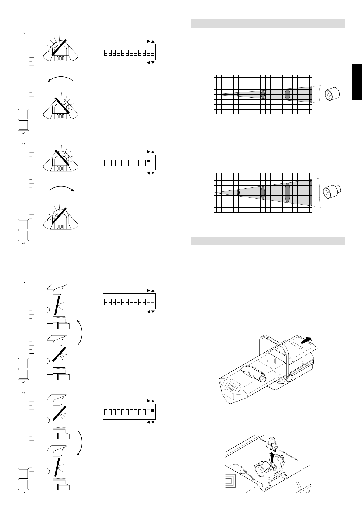
•
PAN - channel 3
Standard operation
Horizontal movement (Pan) of the mirror
is linear and continuous in response to
the movement of the slider, occurring
gradually and uniformly between 0 and
10 on the scale.
The mirror can be stopped at any angle
within the range of adjustment.
Optional operation
The starting position and the direction of
movement can be reversed.
The panning movement of the mirror is
produced in exactly the same way (see
previous paragraph).
•
TILT - channel 4
TEST
256
128
6432168421
ON
10987654321 11 12
PAN
TILT
0
1
2
3
4
5
6
7
8
9
10
TILT
PAN
12111234567 8910
ON
1248163264
128
256
TEST
0
1
2
3
4
5
6
7
8
9
10
Standard operation
Vertical movement (Tilt) of the mirror is
linear and continuous in response to the
movement of the slider , occurring gradually and uniformly between 0 and 10 on the
scale.
The mirror can be stopped at any angle
within the range of adjustment.
Optional operation
The starting position and the direction of
movement can be reversed.
The tilting movement of the mirror is produced in exactly the same way (see previous paragraph).
LENS UNITS
5
GRAPHS SHOWING BEAM DATA AND ILLUMINATION VALUES
MAINTENANCE
6
IMPORTANT: isolate the projector from the electrical power supply before commencing maintenance work of any description..
The maximum temperature on the outer surface of the projector under normal operating conditions is 100°C (212° F). After switching off, do not remove any part of the
projector for at least 10 minutes, as indicated on the lamp change label (1).Once this
time has elapsed, the risk of a lamp exploding is practically zero.If the lamp needs
changing, wait a further 15 minutes to avoid the risk of burns. In the event of a lamp
exploding, the appliance is designed to prevent fragments of glass from being scattered. Lenses and clear filters supplied with the appliance must be fitted at all times,
and if visibly damaged must be replaced promptly with genuine spares.
•
Opening the projector
Remove the lamp access cover (8) from the projector by pushing in the direction
arrowed. Once the necessary work has been completed, refit the cover (8).
1
8
9
10
•
Changing the lamp (MINISCAN 150)
Remove the lamp (9) from its fitting (10), withdrawing in the v ertical direction.Locate
the new lamp in the fitting, ensuring that the pins are positioned correctly.
ENGLISH
Objective 1:2,5/165mm - Standard equipment
Miniscan 300 (HMD) (lux)
Miniscan 300 (HMD) (fc)
Miniscan 300 (HTI) (lux)
Miniscan 300 (HTI) (fc)
Miniscan 150 (HTI) (lux)
Miniscan 150 (HTI) (fc)
4
3
2
1
0
1
2
BEAM OPENING m
3
4
0 5 10 20
0” 16’ 5”
0 0,8 1,60 3,20
0” 2’ 7”
1980 495 220
184 46 20,4
2610 650 290
242 60,4 26,9
1400 370 161
130 34,4 15
32’ 10” 49’ 3” 65’ 7”
5’ 3” 7’ 10” 10’ 6”
15
2,40
Objective 1:2,2/100mm - Available on request
Miniscan 300 (HMD) (lux)
Miniscan 300 (HMD) (fc)
Miniscan 300 (HTI) (lux)
Miniscan 300 (HTI) (fc)
Miniscan 150 (HTI) (lux)
HMI 1200
Miniscan 150 (HTI) (fc)
4
3
2
1
0
1
2
BEAM OPENING m
3
4
0 5 10 15 20
0” 16’ 5”
0 1,34 2,70 4,05 5,40
0” 4’ 5”
780 195 87
72,5 18,1 8,08
1000 250 111
92,9 23,2 10,3
500 125 55
46,5 11,6 5,11
32’ 10” 49’ 3” 65’ 7”
8’ 10” 13’ 3” 17’ 9”
124
11,5
165
15,3
90
8,36
49
4,55
62
5,76
32
2,97
9°
DISTANCE m
DISTANCE ft in
DIAMETER m
DIAMETER ft in
°
15,4
DISTANCE m
DISTANCE ft in
DIAMETER m
DIAMETER ft in
Page 4
10
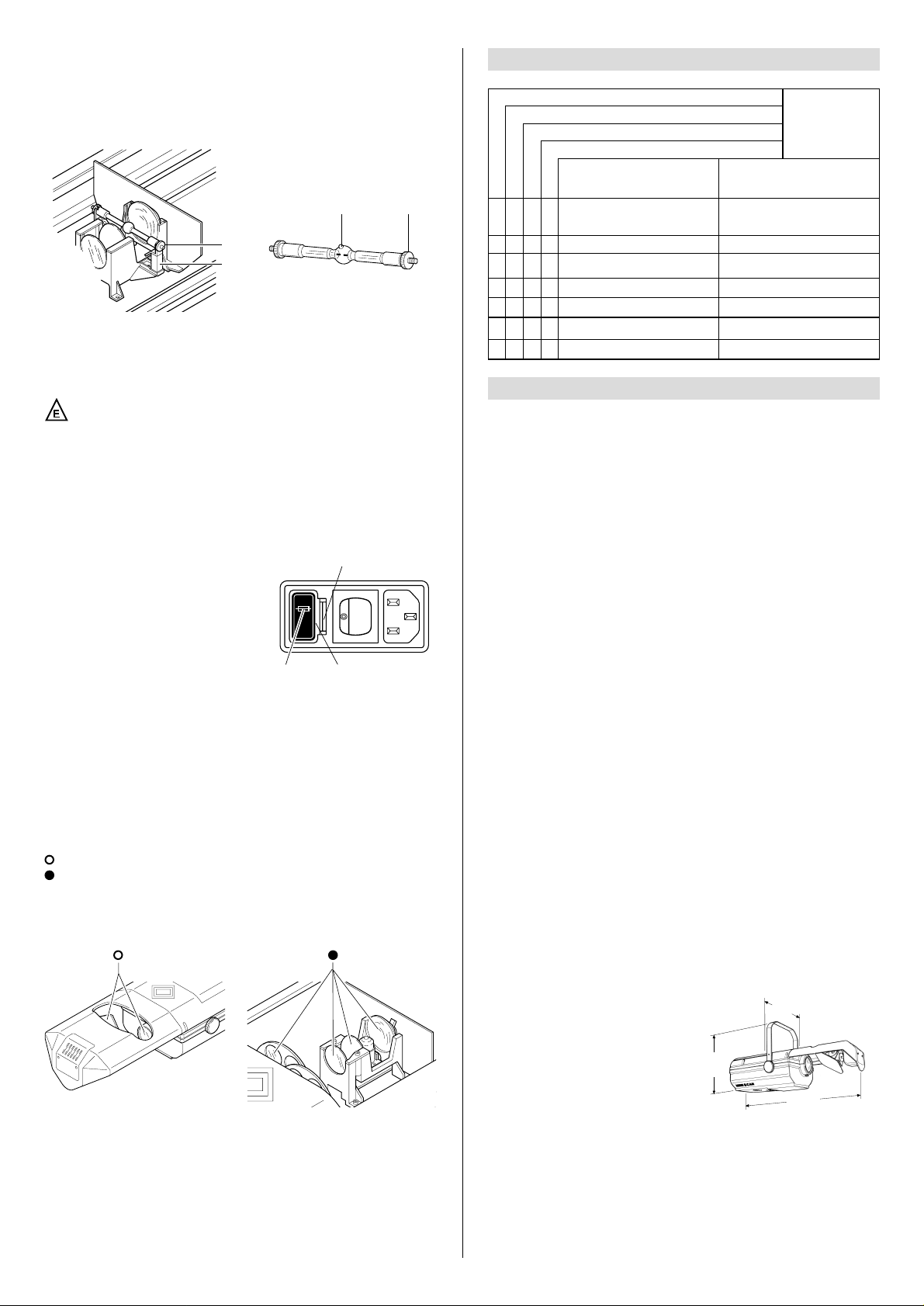
•
Changing the lamp (MINISCAN 300)
Open the projector, loosen the two side nuts (11) of the lamp to be changed and
remove it from the supports (12).
Remove the new lamp from its packaging, loosen the two side nuts (11) and locate
the lamp in the supports (12). Finally, retighten the nuts.
IMPORTANT: f or unif orm distribution of the light beam, the lamp must be positioned
so that the glass pip (13), on the bulb does not coincide with the optical axis of the
projector.With this in mind, locate the pip as high up as possible.
CAUTION: The projector uses a high pressure discharge lamp with
external starter.
• Routine cleaning
To maintain the light output of the projector undiminished, par ts that tend to accumulate dust and grease must be cleaned periodically.
In most circumstances, the projector will give long and trouble-free service if these
simple guidelines are followed.
To remove dirt from the lenses and filters, use a soft cloth moistened with any liquid
detergent suitable for cleaning glass.
IMPORTANT: do not use solvents or alcohol
Parts that need cleaning frequently.
Parts that need cleaning monthly.
Internal components should also be given a general clean once a year, dislodging
dust and dirt with a brush and removing it simultaneously with a vacuum cleaner.
• Replacing fuses
To change the fuses, press the tab (14) and
pull out the fuse holder (15). Replace any
blown fuse with one of the same type and rating as indicated on the label (16) attached to
the holder (15). Insert the fuse holder and
push in to engage the tab (14).
CAUTION:
- When fitting a new lamp, read the manufacturer’s instructions carefully.
- The lamp must always be changed without delay if damaged or deformed by heat.
14
15
16
TROUBLESHOOTING
7
No electrical power supply. Check that power is available at the
mains socket and/or that fuses are
intact.
PROJECTOR DOES NOT LIGHT UP
ELECTRONICS NOT WORKING
FAULT
PROJECTION FAULTY FAULTS
REDUCED BRIGHTNESS
POSSIBLE CAUSES CHECKS AND REMEDIES
•
•
•
•
•
•
••
•
Lamp expended or faulty.
Change lamp (see instructions).
Signal transmission cable short-circuiting or disconnected.
Change cables.
Address codes incorrect. See projector coding instructions.
Defect in electronic circuits.
Contact an authorized technician.
Lenses broken. Contact an authorized technician.
Deposit of dust or grease. Clean (see instructions).
TECHNICAL DATA
8
11
12
13 11
ELECTRICAL/MECHANICAL
SPECIFICATION
Power supply
MINISCAN
•
220 - 240V 50Hz
•
200V 50Hz - 230V 60Hz
•
200V 60Hz
MINISCAN 300
Metal iodide type with special built-in
power supply unit.
• Type HMD 300W
- Cap SFc 10-4
- Colour temperature 5000 K
- Luminous flux 18000 lm
- Average life 3000 h
• Type HTI 300W
- Cap SFc 10-4
- Colour temperature 6500 K
- Luminous flux 22000 lm
- Average life 750 h
MINISCAN 150
Metal iodide type with special built-in
power supply unit.
• Type HTI 150W
- Cap GY 9.5
- Colour temperature 6900 K
- Luminous flux 9500 lm
- Average life 750 h
Power consumption
•
MINISCAN 300: 800VA at 220V 50Hz
•
MINISCAN 150: 500VA at 230V 50Hz
Motors
N. 4 microstepping motors with full microprocessor control.
OPTICAL SYSTEM
Optical unit
Main optical unit in diecast aluminium,
incorporating twin lens condenser and a
reflector of high luminous efficiency.
Lens units
•
Standard:1:2,5/165 mm (9°).
•
Optional: 1:2,2/100 mm (15°20’).
MIRROR HEAD
Mirror of ultra high luminous efficiency.
Movement
•
Produced by two controlled microstepping motors.
•
Infinitely variable speed of rotation;
maximum values:
-
horizontal (PAN) = 0.4 sec (150°)
- vertical (TILT) = 0.3 sec (110°)
•
Continuous and uniform movement.
Resolution:
- PAN = ±0.3° (150°)
- TIL T = ±0.2° (110°)
CONTROL SYSTEMS
Channels
N. 4 control channels.
Inputs
The MINISCAN is set up to accept analog
or digital signals from controllers or computers.
•
Digital serial input: RS232/423(PMX) or
DMX 512
•
Analog input 0-10V
GENERAL CHARACTERISTICS
Safety devices
•
Power supply shuts off automatically in
the event of overheating or cooling system failure.
•
Power shuts off automatically when cov er
is opened (MINISCAN 300 only).
Cooling
Forced ventilation cooling system using
axial flow fans.
Housing
•
Extruded die-cast aluminium.
.
•
Epoxy powder coated finish.
Mounting
•
Steel bracket with epoxy powder coated
finish.
•
Two installation positions, 50 mm (2”) apart.
•
Bracket adjustable through 110°.
Operating position
Will function in any position.
Weights and dimensions
•
MINISCAN 300: 10.5 kg.(23 lbs 2 ozs)
•
MINISCAN 150: 8.5 kg. (18 lbs 11 ozs)
(9.4”)
238
(22.9”)
582
(11”)
280
FUSE
5 x 20
5A T
250 V
Page 5

11
ELECTRICAL DIAGRAM
9
ENGLISH
The products referred to in this manual comply with
EC Directives on:
• Low Voltage 73/23
• Electromagnetic Compatibility 89/336
The specifications published in this manual are not binding, and may be revised or updated
at any time by Clay Paky without notice in the interests of improving product quality.
MINISCAN 300
MINISCAN 150
 Loading...