

Page 1
• Minimum distance of inflammable materials from any part of the fixture:
0.10 m (4”) for QS and HMI 1200 Basic versions, 0.07 m (3”) f or HMI 575 Basic v ersion.
The fixture may be mounted on surfaces rated normally inflammable.
IMPORTANT: For better and more reliable operation of the projector, the ambient
temperature must not exceed 35° C (95° F). Protection factor IP 20: the fixture is protected against penetration of solid bodies more than 12 mm (0.5”) in diameter (first
digit 2), but can be damaged by spray, jet, drip or rain water (second digit 0).
ENGLISH
SHADOW
POWER SUPPLY AND INTERFACE
2
• Connecting to the electrical power supply
The operations described in this heading must be carried out by a licensed
electrician.
It is good policy to connect projectors to the power supply by way of dedicated
switches, so that each can be turned on and off individually from a remote station.
INST ALLING THE PROJECTOR
1
IMPORTANT: Read carefully. It is essential for the correct and safe use of
the equipment that erectors and operators should be fully conversant with
the information and instructions given in this manual.
INSTRUCTION MANUAL
2
5
4
6
7
3
1
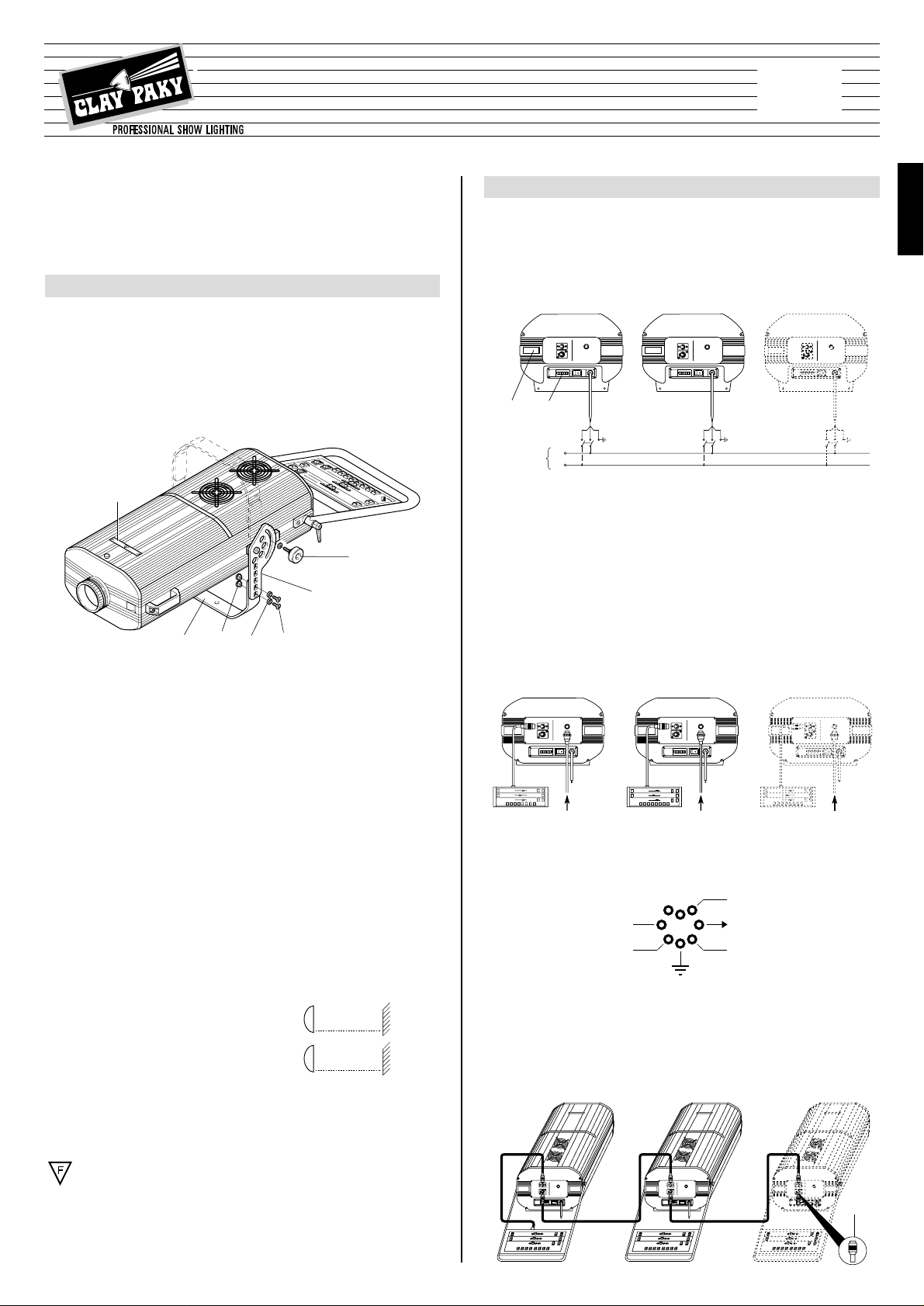
• Unpacking
Open the wooden box, remove the projector from the packing and place it on a flat
horizontal surface. Unpack the standard accessories supplied with the equipment.
Inspect the lamp change label (1) on the projector cover and replace it with one of the
optional language versions if necessary.
Make certain that the label is never removed, as it displays important safety
information.
• Initial assembly operations
Position the bracket (2) on the graduated plate (3) at the desired height, select the
required hole and insert the bushing (4), the chamfered washer (5) and the screw (6)
and tighten the assembly using the supplied Allen wrench.
The bracket can also be mounted on the top of the projector for truss mounting by
inverting the position of the graduated plate (3).
Position the support as desired and then secure it by tightening the knobs (7).
• Fitting the lamp
Refer to directions for replacement of the lamp given under heading 8 MAINTENANCE.
• Installing the projector
The projector can be mounted in any position without its operating characteristics
being affected.
IMPORTANT: for ceiling installation secure the projector in the desired position by
means of the holes in the support. Secure preferably using two ø12 mm bolts with
nuts and lock washers.
Make certain that the anchorage is stable before positioning the projector.
• Minimum distance from target objects
The projector must be positioned in such a way
that objects struck by the beam are separated from
the fixture by at least the distance specified on the
lamp change sticker next to the symbol shown in
the figure on the right.
The projector is designed to operate at the voltage and frequency indicated on the
electrical data plate (8) affixed to the rear end.
Check that these two values correspond to the mains voltage and frequency.
IMPORTANT: the projector must be connected to a power supply circuit having
a proper earth system (Class I appliance).
N
L
Mains
8
10
9
0 - 10V 0 - 10V 0 - 10V
• Connecting the control signals
SHADOW BASIC followspots can be controlled only from the integr ated control panel,
while SHADOW QS models can also be controlled from a remote external controller.
0-10V CONNECTION
When both the external 0-10V controller and the integrated control panel are connected, the higher level signal assumes priority.
The connection between projector and controller must be made using a multicore
cable with 8 wires of 0.25mm
2
section and a DIN 8 pin 45° plug/socket connector.
RS 232/423(PMX) - DMX 512 CONNECTION
- Several Shadow followspots can be controlled simultaneously from the integrated
control panel on one fixture.
7
ENGLISH
QS-ST HMI 1200
QS-LT HMI 1200
Basic HMI 1200
Basic HMI 575
®
(8’ 2”)
2.5 m
(5’ 11”)
1.8 m
HMI 1200
HMI 575
DIM 4
TEMP
1 IRIS
3 DIM
STOP
Is
COL 2
Page 2
• COLOUR TEMPERATURE CONVERSION - channel 4
0
1
2
3
4
5
6
7
8
9
10
The warm filter is inserted from 0% to
33.2% of slider movement, no filter is
present from 33.7% to 67.0%, and the
cool filter is inserted from 67.5% to
100% of slider movement.
Cold Filter
Warm Filter
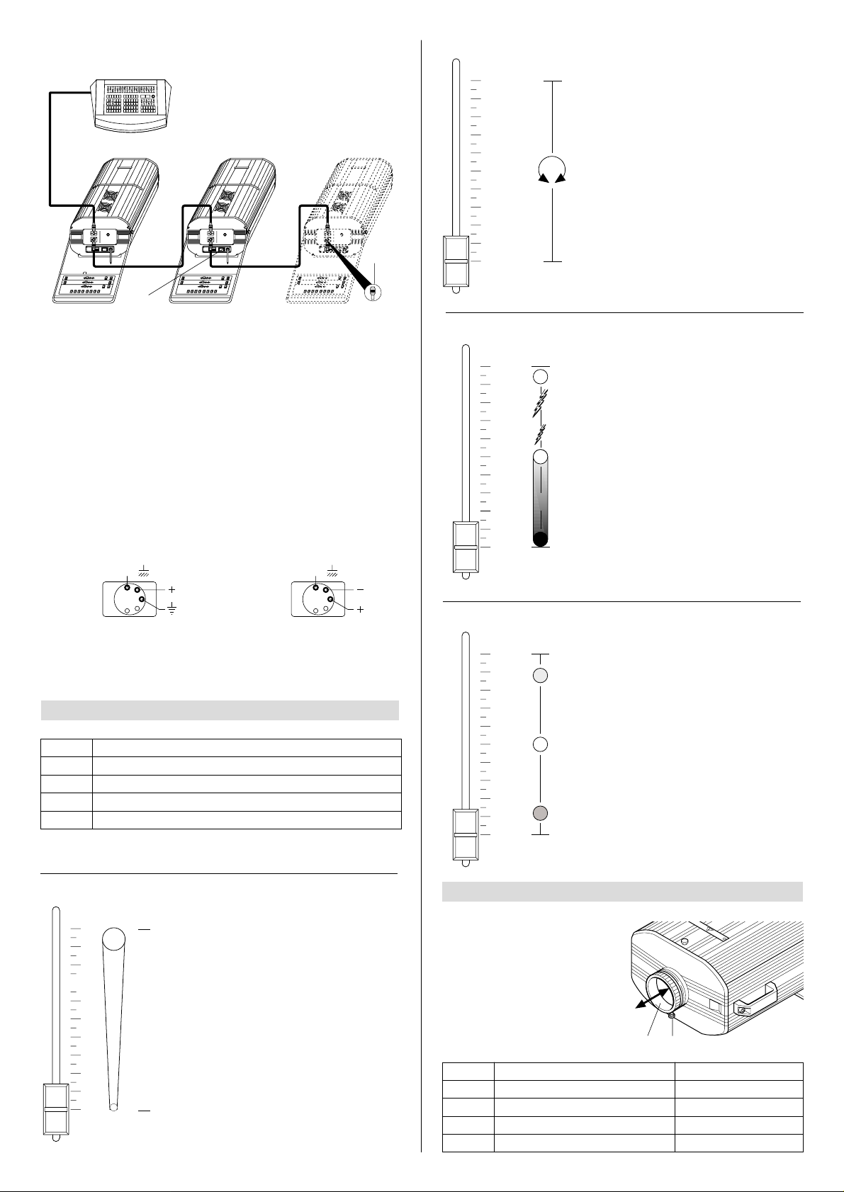
To enable independent operation of several Shadow projectors each must be
assigned a unique address code.This procedure calls for the presence of an authorized technician.
Projectors are wired up to the controller and one to the next using two-core screened
cable and Cannon 5 pin XLR type plug/socket connectors.
To connect a DMX line, a ter minating plug (9) with a 100 Ω resistor wired between
pins 2 and 3 must be fitted to the last projector connected in series; the plug is not
required when using an RS232/423(PMX) signal.
The wires must not come into contact with each other or with the metal casing
of the plug.
The casing of the plug/socket must be connected to the screen and to pin 1 of
the connectors.
Having completed the operations described above, press the on/off switch (10).
Check that the lamp comes on and that the auto-reset sequence starts.
CHANNELS FUNCTION (SHADOW QS)
3
FOCUSING
4
• IRIS - channel 1
0
1
2
3
4
5
6
7
8
9
10
The response of the iris to the movement of the potentiometer is linear and
continuous through the full 0… 100%
range, so that the slider can be
stopped in any position to obtain the
desired aperture diameter.
100%
0%
In the 0% to 50% range of adjustment
the dimmer opens gradually to maximum aperture. Strobe effect is produced from 54.7% to 95% with frequency increasing from 1 to 7 flashes/second. The aperture remains
fixed from 95% to 100% of the slider
range.
• DIMMER/STOPPER/STROBE - channel 3
• COLOUR WHEEL - channel 2
WHITE
RED
YELLOW
VIOLET
GREEN
ORANGE
BLUE
PINK
0
3
5
7
8
9
6
4
2
1
10
The change of colour in response to
movement of the potentiometer is linear and continuous, so that the slider
can be stopped in intermediate positions to obtain a two colour beam.
• Focusing - QS-ST version
Set up the channels as shown in
the table. Unscrew knob (11) and
move the lens (12) forwards and
back until the projected image is
perfectly sharp.Secure the lens by
tightening knob (11).
- When connected to an external controller , se v eral projectors can be controlled either
simultaneously or independently.
9
10
8
12 11
CHANNEL FUNCTION
1 IRIS
2 COLOUR WHEEL
3 DIMMER/STOPPER/ STROBE
4
COLOUR TEMPERATURE CONVERSION
POSITION
100% (
Maximum aperture
)
0% (
White
)
100% (
Open
)
0% (
White
)
CHANNEL FUNCTION
1 IRIS
2 COLOUR WHEEL
3 DIMMER/STOPPER/ STROBE
4 COLOUR TEMPERATURE CONVERSION
RS232/423
(PMX)
SCREEN
1
2
3
45
SIGNAL
SIGNAL
DMX
512
SCREEN
1
54
2
3
SIGNAL
SIGNAL
10
9
8
7
6
5
4
3
2
1
0
Page 3
• Focusing - QS-LT version
Tur n knob (13) on the rear of the projector
until the projected image is perfectly
sharp; this procedure can be checked
by means of the pointer (14) which
provides an indication of the focusing distance as shown on
label (15).
13
14
15
The controls are on the dedicated panel which can be tilted downwards through an
angle of 90° star ting from a position on the same axis as the projector body.
KEY
A) 8 push buttons with indicator lights for insertion of fixed colours with two-colour
beam function by pressing two adjacent buttons simultaneously;
B) 2 flash buttons for instant iris opening;
C) 2 flash buttons for instant stopper opening;
D) 1 potentiometer for iris aperture adjustment;
E) 1 potentiometer for adjusting the dimmer aperture or strobe frequency;
F) 1 potentiometer for adjusting the rotation speed of the colour wheel
(with selector I set to rainbow);
G) 1 dimmer or strobe selector;
H) 1 colour temperature conversion selector;
I) 1 rainbow effect or fixed colour selector.
QS CONTROL PANEL
5
AIH
G
FDE BCBC
KEY
A) 2 flash buttons for instant stopper opening;
B) 2 flash buttons for instant rainbow effect;
C) 2 flash buttons for instant iris opening;
D) 1 selector for dimmer or strobe effect;
E) 1 selector for rainbow effect or fixed colours;
F) 1 potentiometer for iris aper ture adjustment;
G) 1 potentiometer for rainbow speed adjustment or selection of fixed colour;
H) 1 potentiometer for dimmer aperture adjustment or strobe frequency.
BASIC CONTROL PANEL
6
DH
G
BAAB
CFE C
LENS UNITS
7
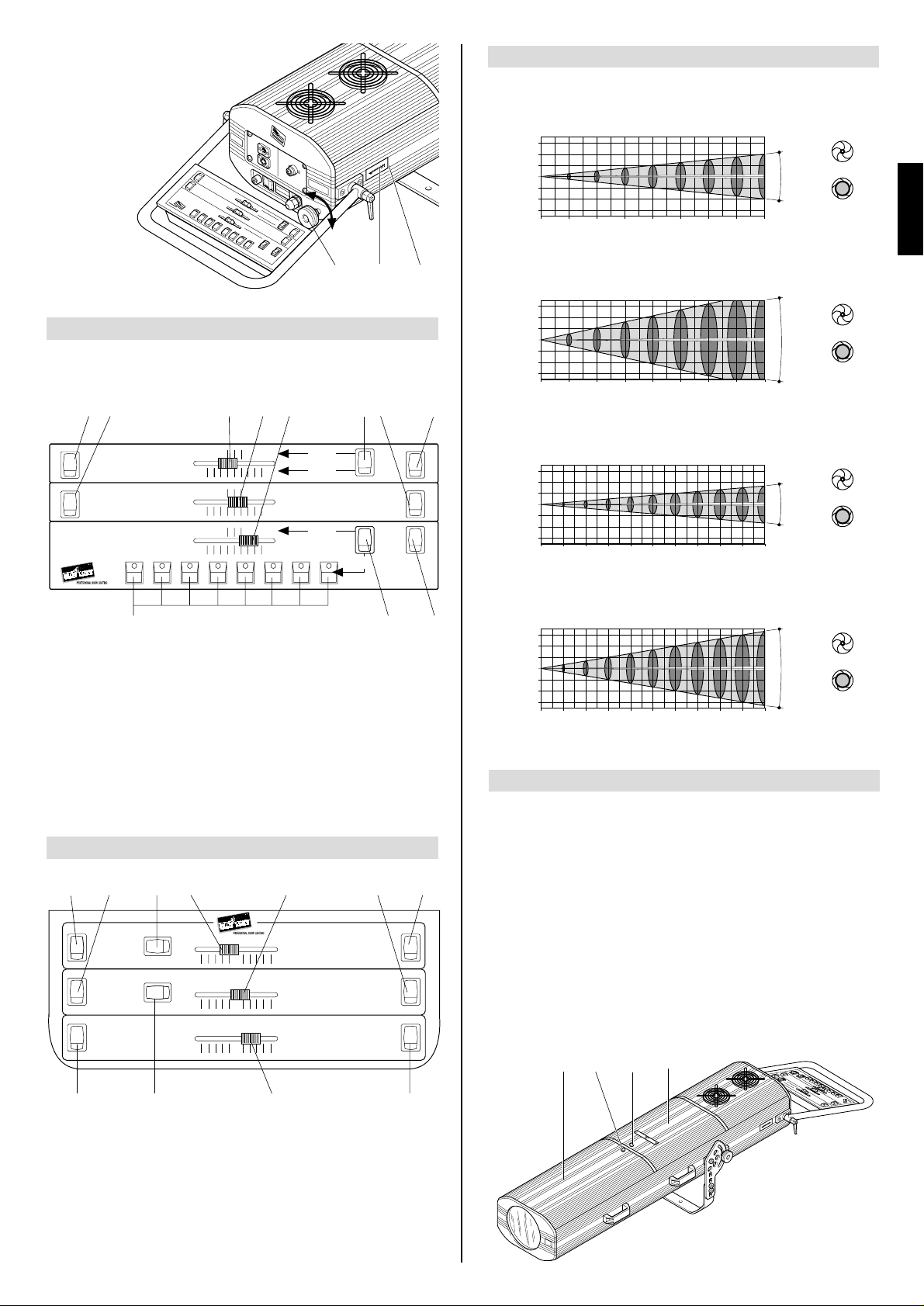
GRAPHS SHOWING BEAM DATA AND ILLUMINATION VALUES
MAINTENANCE
IMPORTANT: isolate the projector from the electrical power supply before commencing maintenance work of any description.
The maximum temperature on the outer surface of the projector under normal
operating conditions is 90°C (194° F) for QS and Basic HMI 1200 versions, and
80°C (176° F) for the Basic HMI 575 version.
After switching off, do not remove any part of the projector for at least 10 minutes, as
indicated on the lamp change label (1).
Once this time has elapsed, the risk of a lamp exploding is practically zero.If the lamp
needs changing, wait a further 20 minutes to avoid the risk of burns.In the event of a
lamp exploding, the projector is designed to prevent fragments of glass from being
scattered.The lenses supplied with the projector must be fitted at all times, and if visibly damaged must be replaced promptly with genuine spares.
• Opening the projector
Loosen knob (16) to remove the lamp access cover (17) or loosen knob (18) to
remove the front cover (19).Once the necessary work has been completed, refit the
cover and tighten with the relative knob.
8
19
18
17
16
ENGLISH
9
STROBE
DIMMER
FIXED
COLOURS
6.000 K
5.600 K
3.200 K
OPEN
OPEN
OPEN
STOP
OPEN
IRIS
COLOUR
WHITE RED YELLOW MAGENTA GREEN ORANGE BLUE VIOLET
®
OPEN SLOW FAST OPEN
0 % 100 %
CLOSED OPEN
0 % 10 %
SLOW FAST
0 % 10 %
RAINBOW
STOP
®
0 100
STROBO
5
STOP
HMI 1200 (lux)
HMI 1200
HMI 1200 (lux)
HMI 1200
HMI 1200 (lux)
HMI 1200
HMI 1200 (lux)
HMI 1200
6m
BEAM OPENING
6m
6m
BEAM OPENING
6m
6m
BEAM OPENING
6m
6m
BEAM OPENING
6m
QS-ST / BASIC - Standard objective
25600 6400 2844 1600 1000 711 520 400
(fc)
2,378 595 264 149 92.9 66.1 48.3 37.2
4
2
0
2
4
0 5 10 15 20 25 30 35 40
0” 16’ 5”
32’ 10” 49’ 3” 65’ 7” 82’ 98’ 5” 114’ 10” 131’ 3”
0 1,0 2,0 3,0 4,0 5,0 6,0 7,0 8,0
0” 3’ 3”
6’ 7” 9’ 10” 13’ 1” 16’ 5” 19’ 8” 23’ 26’ 3”
QS-ST / BASIC - Wideangle objective
3950 990 440 245 160 110 80 62
(fc)
367 92 40.9 22.8 14.9 10.2 7.43 5.76
4
2
0
2
4
0 5 10 15 20 25 30 35 40
0” 16’ 5”
32’ 10” 49’ 3” 65’ 7” 82’ 98’ 5” 114’ 10” 131’ 3”
0 2,2 4,3 6,5 8,6 10,8 12,9 15,0 17,2
0” 7’ 3”
14’ 1” 21’ 4” 28’ 3” 35’ 5” 42’ 4” 49’ 3” 56’ 5”
QS-LT - Standard objective
33750 8437 3750 2110 1350
3,135 784 348 196 125
(fc)
4
2
0
2
4
0 1020304050607080
0”
32’ 10” 65’ 7” 98’ 5” 131’ 3”
0 0,7 1,4 2,0 2,7 3,3 4,0 4,6 5,3
0”
2’ 4” 4’ 7” 6’ 7” 8’ 10” 10’ 10” 13’ 1” 15’ 1” 17’ 5” 19’ 8” 22’
164' 1" 196' 10" 229' 8" 262' 6" 295' 3" 328' 1"
90 100
6,0 6,7
QS-LT - Wideangle objective
10935 2730 1215 685 440
1,016 254 113 63.6 40.9
(fc)
4
2
0
2
4
0 1020304050607080
0”
32’ 10” 65’ 7” 98’ 5” 131’ 3”
0 1,3 2,7 4,0 5,3 6,6 8,0 9,3 10,6
0”
4’ 3” 8’ 10” 13’ 1” 17’ 5” 21’ 8” 26’ 3” 30’ 6” 34’ 9” 39’ 1” 43’ 8”
164' 1" 196' 10" 229' 8" 262' 6" 295' 3" 328' 1"
90 100
11,9 13,3
340415940 690 530
31.638.687.3 64.1 49.2
110120300 225 170
10.211.127.9 20.9 15.8
11,5°
DISTANCE m
DISTANCE ft in
DIAMETER m
DIAMETER ft in
24,6°
DISTANCE m
DISTANCE ft in
DIAMETER m
DIAMETER ft in
4°
DISTANCE m
DISTANCE ft in
DIAMETER m
DIAMETER ft in
7,4°
DISTANCE m
DISTANCE ft in
DIAMETER m
DIAMETER ft in
closed iris
open iris
closed iris
open iris
closed iris
open iris
closed iris
open iris
COLOUR
IRIS
RAINBOW
0 1005
0 1005
COLOUR
IRIS
Page 4

IMPORTANT: do not use solvents or alcohol
Parts that need cleaning frequently.
Parts that need cleaning monthly.
Internal components should also be given a general clean once a year, dislodging
dust and dirt with a brush and removing it simultaneously with a vacuum cleaner.
• Changing the lamp
Open the projector, loosen the two
side nuts (20) of the lamp to be
changed and remove it from the supports (21). Remove the new lamp from
its box, loosen the two side nuts (20)
and locate the lamp in the supports
(21). Finally, retighten the nuts.
• Changing the colour filters
Having opened the projector,
identify the filter to be
changed, grip firmly between
thumb and forefinger and push
against the spring clip (23)
until free of the fixed clips (24).
Bend the filter outwards and
remove.
Offer the new filter to the
spring clip (23) and anchor
behind the two fixed clips (24).
IMPORTANT: for uniform distribution of
the light beam, the lamp must be positioned so that the glass pip (22) on the
bulb does not coincide with the optical
axis of the projector. With this in mind,
locate the pip as high up as possible.
CAUTION: The projector uses a high pressure lamp with external starter.
- When fitting a new lamp, read the manufacturer's instructions carefully.
- The lamp must always be changed without delay if damaged or deformed by
heat.
20
21
25
2726
24
23
• Installing wide angle lenses
Remove the projector front
cover. Unscrew knobs (25),
rotate the front lens plate (26)
from the parking position to
the operating position in
alignment with the projector
axis and then perform the
same operation with the rear
lens plate (27).
Refit the knobs and secure
the two lens plates.
• Lubrication of sliding contact
parts - QS LT
To ensure perfect operation of sliding contact parts of the projector, lubricate sparingly at 6-monthly intervals using Kernite
Lube-K-AC grease.
• Routine cleaning
To maintain the light output of the projector undiminished, parts that tend to accumulate dust and grease must be cleaned periodically.
In most circumstances, the projector will give long and trouble-free service if these
simple guidelines are followed.
To remove dirt from the lenses and filters, use a soft cloth moistened with any liquid detergent suitable for cleaning glass.
TROUBLESHOOTING
9
10
No electrical power supply . Check that power is availab le at the
mains socket.
ELECTRONICS NOT WORKING
PROJECTOR DOES NOT LIGHT UP
PROJECTION FAULTY FAULTS
ANOMALIES
REDUCED BRIGHTNESS
POSSIBLE CAUSES
CHECKS AND REMEDIES
•
•
•
•
•
•
•
••
Lamp expended or faulty. Change lamp (see instructions).
Signal transmission cable shortcircuiting or disconnected.
Change cables.
Address codes incorrect.
See projector coding instructions.
Defect in electronic circuits. Contact an authorized technician.
Lenses broken. Contact an authorized technician.
Deposit of dust or grease. Clean (see instructions).
20
22
Page 5
TECHNICAL DATA
10
ELECTRICAL
MECHANICAL SPECIFICATIONS
Power supply
• 220 - 240V 50Hz
• 200 - 220V 60Hz
Lamp
Metal halide with special built-in power
supply.
• Type: HMI 1200W
- Cap: SFc 15.5-6
- Colour temperature: 6000 K
- Luminous flux: 110000 lm
- Average life: 750 h
• Type: HMI 575W
- Cap: SFc 10-4
- Colour temperature: 6000 K
- Luminous flux: 49000 lm
- Average life: 750 h
Power consumption
• QS-ST/LT HMI 1200:
1500VA at 230V 50Hz
• BASIC HMI 1200:
3000VA at 230V 50Hz
• BASIC HMI 575:
1500VA at 230V 50Hz
Motors
N. 4 (BASIC) N. 5 (QS) microstepping
motors with full microprocessor control.
OPTICAL SYSTEM
Main optical unit
• Base in diecast aluminium.
• Twin lens condenser.
• High luminous efficiency spherical
reflector.
Lens unit
QS-ST and BASIC
• Standard: 1:2.5/250mm
• Optional: wide angle for insertion
inside the projector.
QS-LT
Special optics with wide angle lens as
standard (manual insertion).
CONTROL SYSTEMS
Channels
N. 3 control channels (BASIC)
N. 4 control channels (QS)
Inputs
SHADOW QS is set up to accept analog
or digital signals from controllers or
computers:
• Digital serial input
RS232/423(PMX) or DMX512
• 0-10V analog input
CONSTRUCTION
FEATURES
Safety devices
• Power shuts off automatically in the
event of ov erheating or cooling system
failure.
• Power shuts off automatically when
cover is opened.
Cooling
Forced ventilation cooling system using
axial flow fans.
Housing
• Extruded diecast aluminium.
• Epoxy powder coated finish.
Mounting
• Steel bracket with epoxy powder coat-
ed finish.
• Six installation positions, 25 mm
apart.
• Bracket adjustable through 100° with
graduated scale for position finding.
Operating position
Will function in any position.
Weights and Dimensions
•
QS-ST HMI 1200: 38 kg ( 83 lbs 10 ozs)
• QS-LT HMI 1200: 49 kg
(107 lbs 13 ozs)
• Basic HMI 1200: 38 kg
( 83 lbs 10 ozs)
• Basic HMI 575: 30 kg
( 66 lbs)
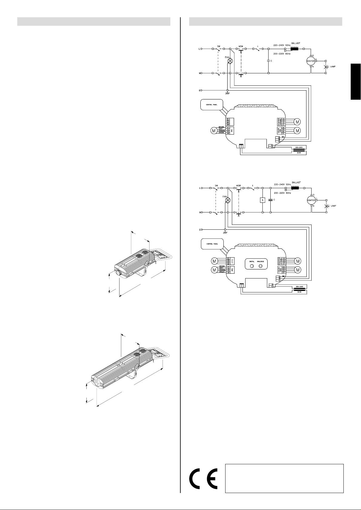
WIRING DIAGRAM
11
(67.5”)
1715
(17.1”)
435
(13”÷17.5”)
330÷445
(17.1”)
435
(13”÷17.5”)
330÷445
(46.3”)
1175
SHADOW Basic HMI 575
SHADOW Basic HMI 1200
SHADOW QS ST HMI 1200
SHADOW QS-LT HMI 1200
ENGLISH
11
The products referred to in this manual comply with
EC Directives on:
• Low Voltage 73/23
• Electromagnetic Compatibility 89/336
The specifications published in this manual are not binding, and may be revised or updated
at any time by Clay Paky without notice in the interests of improving product quality.
BASIC
QS-ST - QS-LT
 Loading...