

Page 1
1
GOLDEN SCAN HPE
ENGLISH
HMI 1200
®
• Installation
Make sure all the parts for fixing the projector are in a good state of repair.
Make sure the point of anchorage is stable before positioning the projector.
The safety rope, properly hooked onto the fitting and secured to the framework, must
be installed so that, if the primary support system fails, the fitting falls as little as
possible. If the safety rope gets used, it needs to be replaced with a genuine spare.
• Minimum distance of illuminated objects
The projector needs to be positioned so that
the objects hit by the beam of light are at least
2.5 metres from the lens of the projector.
• Minimum distance of flammable materials
The projector must be positioned so that any flammable materials are at least
0.1m (4”) from every point on the surface of the fitting.
SAFETY INFORMATION
1
INSTRUCTIONS MANUAL
Carefully read this instructions manual in its entirety and keep it safe for future
reference.
It is essential to know the information and comply with the instructions given
in this manual in order to ensure the fitting is installed, used and serviced
correctly and safely.
CLAY PAKY S.p.A. disclaims all liability for damage to the fitting or to other
property or persons deriving from installation, use and maintenance that have
not been carried out in conformity with this instructions manual, which must
always accompany the fitting.
CLAY PAKY S.p.A. reserves the right to modify the characteristics stated in
this instructions manual at any time and without prior notice.
Congratulations on choosing a Clay Paky product! We thank you for your
custom. Please note that this product, as all the others in the rich Clay Paky
range, has been designed and made with total quality to ensure excellent
performance and best meet your expectations and requirements.
• Maximum ambient temperature
For the fitting to operate well and reliably, the ambient temperature should not
exceed 35°C (95°F).
• IP20 protection rating
The fitting is protected against penetration by solid bodies of over 12mm (0.5”) in
diameter (first digit 2), but not against dripping water, rain, splashes or jets of water
(second digit 0).
• Protection against electrical shock
This fitting is classified in accordance with the type of protection against electrical
shock, in Class I. It must therefore be connected to a power supply system with
efficient earthing.
It is however recommended to protect the supply lines of the projectors from indirect
contact and/or shorting to earth by using appropriately sized residual current
devices.
• Connecting to the supply mains
Connection to the electricity mains must be carried out by a qualified electrical
installer.
Check that the mains frequency and voltage correspond to the frequency and
voltage stated on the electrical data label for which the projector is designed.
This label also gives the input power. Refer to this to evaluate the maximum number
of fittings to connect to the electricity supply in order to avoid overloading.
• Maintenance
Before starting any maintenance work or cleaning the projector, cut off power from
the mains supply.
After switching off, do not remove any parts of the fitting for 10 minutes.
After this time the likelihood of the lamp exploding is virtually null. If it is necessary to
replace the lamp, wait for another 15 minutes to avoid getting burnt.
The fitting is designed to hold in any splinters produced by a lamp exploding.
The lenses must be fitted and, if visibly damaged, they have to be replaced with
genuine spares.
• Temperature of the external surface
The maximum temperature that can be reached on the external surface of the fitting,
in a thermally steady state, is 90°C (194°F).
• Lamp
The projector mounts a high-pressure lamp that needs an external igniter.
This igniter is fitted onto the projector.
- Carefully read the "operating instructions" provided by the lamp manufacturer.
- Immediately replace the lamp if damaged or deformed by heat.
It is permissible to mount the fitting on normally flammable surfaces.
The products referred to in this manual conform to the
European Community Directives to which they are subject:
• Low Voltage 73/23
• Electromagnetic Compatibility 89/336
(8’2”)
2.5
HMI 1200
Page 2
2
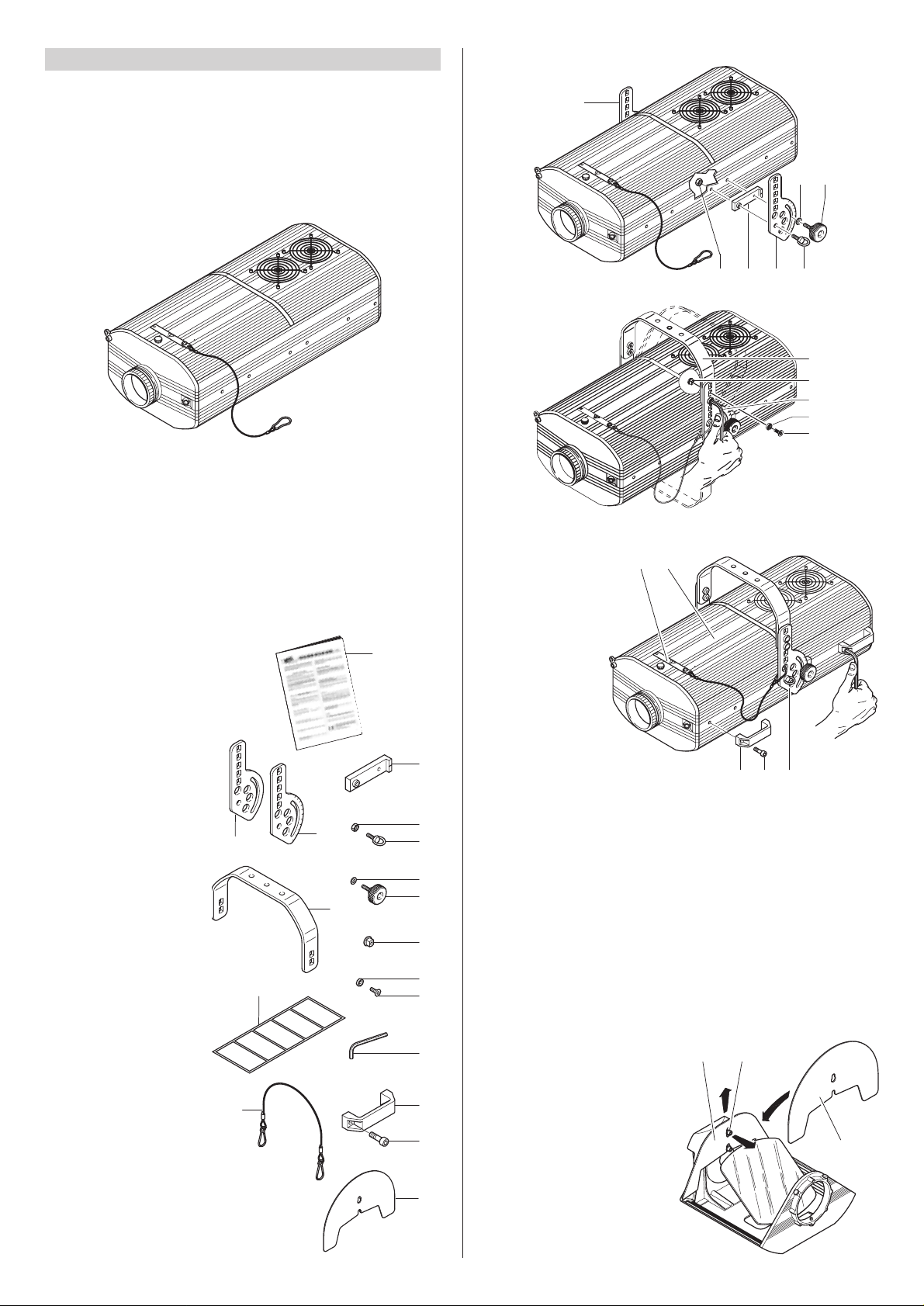
• Packing contents
Besides the projector, the packing also contains the following accessories:
- This instructions manual
code 099410 (1).
-
2 spacers
code 167002/001 (2).
- 1 right bracket support plate
code 167003/001 (3).
- 1 left bracket support plate
code 167003/002 (4).
- 2 eyebolts M8x20mm
code 167004/001 (5).
-
2 nuts M8
code 020106/006 (6).
- 2 knobs code 020502 (7).
- 2 plane washers ø10,5mm
code 020210/004 (8).
-
1 bracket
code 101011/001 (9).
- 4 bracket bushings
code 101014/001 (10).
- 4 countersunk washers
code 080606/001 (11).
- 4 countersunk head
screws M8x20mm
code 020005/001 (12).
- 1 Allen wrench 5 mm
code 050001 (13).
- 4 handles
code 082017/001 (14)
- 8 screws TCEI M8x20
code 020002/029 (15).
- Multilingual label (16) with
safety information
code 081968
(located in the projector
lampholder compartment).
- 1 safety ropes code 105041/001 (17).
- N. 1 large mirror lens hood
code 105039/001 (18).
2
13
14
12
1
4
3
5
6
7
8
9
10
11
15
18
17
16
UNPACKING AND PREPARING
2
• Unpacking
Open the box from the top, take all the accessories out of the box and remove the
polystyrene containing structures.
Open the plastic bag, remove the projector from the box frame and position it on a
horizontal top where access is easy to carry out the following preliminary work.
• Preparing the warning label
Find the warning label (20) on the re-lamping cover (19) and, if necessary, replace it
with one of the optional multilingual labels (16) located in the projector lamp
compartment. For the instructions on opening the projector, read paragraph
4 MAINTENANCE.
CAUTION: Read carefully and meticulously apply the information and
instructions given on this label. In addition, check it is never removed as it
contains important safety information.
• Fitting the bracket
• Fitting the handles
7
6 2 4 5
8
3
12
11
9
10
13
1514 4
20 19
• Fitting the lamp
Refer to the instructions for opening the projector and changing the lamp in
paragraph 4 MAINTENANCE.
• Changing the lens hood
Loosen the screws (21) a few turns
without removing completely, then
dislodge the standard lens hood (22) by
drawing it upwards and inwards, taking
care to avoid contact with the mirror.
Remove the wide-angle mirror head
lens hood (18) out of the projector
packing, and fit it in place of the standard hood.
Check that the lens hood is in the correct
position (slots located fully behind the
screw heads), then retighten the screws.
Verify that the lens hood produces the
required effect by selecting 100% TILT
(with dip-switch 6 off) and sliding the
PAN control from 0% to 100%.
22 21
18
Page 3
3
5
17
5
17
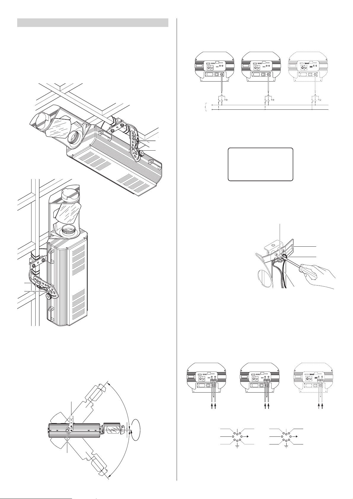
• Installing the projector
The projector can be installed on the ceiling or on a wall through the holes in the
bracket. It is recommended to use 2 screws ø12mm with nut and spring washer
.
CAUTION: Check the plates (3 and 4) are correctly secured to the sides of the
fitting; If the plates has been removed, to carry out non-routine maintenance
work, reposition them, following the relevant instructions and checking the
threads in the projector sides hold properly.
• Securing the safety ropes
Except for when the projector is standing on the floor, it is compulsory to fit the
safety rope (17). These need to be secured to the projector framework and then
hooked onto the eyebolts (5) screwed into the sides of the projector
INSTALLATION AND FINE-TUNING
3
• Adjusting the projector position
180
°
50°
50
°
7
9
GOLDEN SCAN HPE
• Mains power connection
It is advisable to connect each projector via its own switch so as to be able to switch
it on and off individually from a distance.
N
L
10
10
10
23
25
26
24
Mains
BROWN =
BLUE =
YELLOW =
GREEN =
L
N
=
• Selection of voltage/frequency
Open up the effects compartment
of the projector by lifting the
relative cover (see heading
8 MAINTENANCE) and locate the
voltage change terminal (23)
mounted to the effects assembly
frame (24). Use a screwdriver to
disconnect the cable (25) from the
terminal it occupies, and reconnect
to the terminal alongside, referring
to the label (26) alongside the
terminal. Having completed the
operation, refit the cover.
• Connecting the control signals
0-10V CONNECTION
0 - 10V 0 - 10V 0 - 10V
10 10
10
Is
1 IRIS
5 PAN
3
COL (2)
DIM 4
STOP
COL (1)
2
6
TILT
7 FROST
FOCUS +
9
PRISM
8
Is
11 ROT.
ROTATE
12
GOBO
FIXED 10
GOBO
EFFECT
ANGLE
GOBO
The connection between controller and projector must be made using a multifcore
cable with 8 wires of 0,25mm
2
section and a DIN 8 PIN 45° plug/socket connector.
Page 4

4
DIGITAL START ADDRESS SELECT
OPTION SELECT
DIGITAL INPUT LEDS
1
16
124816
1283264
TEST
256
ON
12 436578109
DIGITAL INPUT
ANALOGUE INPUTS
0-10V
• Projector coding
Each GOLDEN SCAN HPE requires 12 control channels. For these to be correctly
addressed to each projector it is necessary to code the projectors. This operation
needs to be carried out on each
GOLDEN SCAN HPE
by switching the microswitches
(31)
according to the table below.
Codes can be assigned with the projector off, although the operation will be easier
with the projector on, as the decade address corresponding to the binary code set
with the microswitches is shown on the 3-digit display (29).
When the information of "Total hours", "Bulb hours”, “Bulb strikes” and “Address" is
scrolling on the display and you use the DIL switches of the addresses (31), the
display will instantly show the new address selected. After a few seconds the above
information will start scrolling again if at least one of the above conditions remains.
On turning the TEST microswitch (32) onto ON the projector runs a self-check,
during which the effects are mechanically reset with the projector on. At the end of
the operation, or whenever you want to interrupt this procedure, turn the TEST
microswitch back onto OFF.
When sending 0% levels to all channels, the unit will start an automatic re-calibration
after 2 seconds. This operation will reposition any effects to their correct settings.
The entire re-calibration cycle lasts approximately 35 seconds and can be stopped
at any time by simply setting a channel at a level above 0. It is recommended not to
interrupt re-calibration, but to let it end regularly, once 10 seconds have elapsed
from its start.
109-120Projector - Channels10
97-108Projector - Channels9
85-96Projector - Channels8
73-84Projector - Channels7
61-72Projector - Channels6
49-60Projector - Channels5
37-48Projector - Channels4
25-36Projector - Channels3
2
1
ON
OFF
ON
OFF
ON
OFF
ON
OFF
ON
OFF
ON
OFF
ON
OFF
ON
OFF
1
2
4
8
163264
128
256
TEST
OFF
ON
OFF
ON
Projector - Channels 13-24
1-12Projector - Channels
CODE
OFF
ON
DIGITAL START ADDRESS SELECT
OPTION SELECT
DIGITAL INPUT LEDS
1
16
124816
1283264
TEST
256
ON
12 436578109
DIGITAL INPUT
ANALOGUE INPUTS
0-10V
The above information can also be displayed by carrying out at least one of the
following operations:
• Setting all the DIL (Dual-In-Line) switches of the addresses (31) onto zero.
• Activating the TEST procedure, turning the specific DIL switch (32) ON.
• Setting the projector on blackout (20 channels starting from the selected starting
address, all at level zero).
31 32 29
28
30
• Switching on the projector
After carrying out all the above operations, press the switch (28) checking it all
works properly.
At switch on, the software contained in the DMX Receiver microprocessor does a
checksum (automatic check) while the three figure display (29) is off and the three
LEDs (30) controlling the input signal are all on. After a few seconds, the projector
starts the mechanical zero setting of the effects. At the same time, if the
checksum has had a positive result, a code corresponding to the version of the
DMX Receiver microprocessor (installed) appears on the display. This code is
displayed for about 5 seconds, then only one of the three LEDs relating to the
connected input signal stays on, while the following information scrolls on the
display once:
in which “Total hours” is the total number of hours of the fitting’s life, “Bulb hours” is
the number of hours of the lamp’s life, “Bulb strikes” is the number of times the lamp
has been switched on and “Address” is the selected starting address for the
projector control signals.
After the information has scrolled, the projector address will stay displayed.
Total hours - XXX Bulb hours - XXX Bulb strikes - XXX Address - XXX
10
10
10
RS232/423
DMX 512
SIGNAL
SCREEN
SIGNAL
54
3
2
1
DMX
512
SIGNAL
SCREEN
SIGNAL
RS232/423
(PMX)
1
2
3
45
RS 232/423(PMX) - DMX 512 CONNECTION
Projectors are wired up to the controller and one to the next using two-core screened
cable and Cannon 5 pin XLR type plug/socket connectors.
To connect a DMX line, a terminating plug (27) with a 100Ω resistor wired between
pins 2 and 3 must be fitted to the last projector connected in series; the plug is not
required when using a RS232/423(PMX) signal.
IMPORTANT: The wires must make no contact with each other or with the metal
casing of the connectors. The casing needs to be connected to the braid of the
shield and to pin 1 of the connectors.
27
About two minutes after the projector has been switched on, the luminous intensity
of the display (29) decreases to 1/32 of the maximum value. The maximum
luminosity is restored automatically if you use the microswitches to select the
DMX address, set the options or activate the TEST function. Approximately two
minutes after the last operation listed above has ended, the luminosity of the display
decreases again.
Page 5

5
DIGITAL START ADDRESS SELECT
OPTION SELECT
DIGITAL INPUT LEDS
1
16
124816
1283264
TEST
256
ON
12 436578109
DIGITAL INPUT
ANALOGUE INPUTS
0-10V
• Zero setting the working hours and number of times the lamp is switched on
To zero the hours of the lamp’s life (“Bulb hours”) and the number of times it is
switched on (“Bulb strikes”) which are stored in the DMX Receiver microprocessor,
proceed as follows:
1. Set the TEST microswitch (32) to the ON position.
2. Shift the option 1 microswitch (37) from ON to OFF (or from OFF to ON) and vice
versa 3 times within a time of 6 seconds. If the procedure has been carried out
correctly, the three signal control LEDs (30) will light up simultaneously, while the
display (29) will go completely blank. This situation lasts for approximately
5 seconds.
3. Return the TEST microswitch (32) to the OFF position.
34
35
36 34
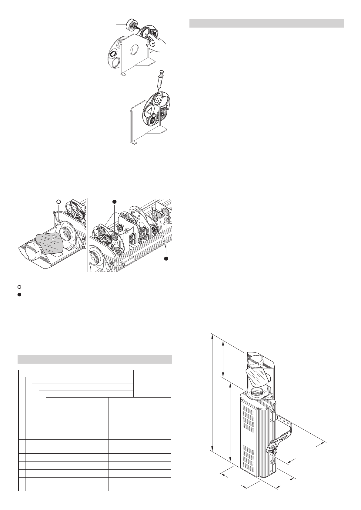
• Changing the lamp
Open the re-lamping cover, loosen the
two side ring nuts (34) of the lamp to be
replaced and remove it from its
mountings (35).
Take the new lamp out of its package,
loosen the two side ring nuts (34) and
insert the lamp in its mountings (35).
Finally, screw on the ring nuts.
WARNING: Do not touch the lamp’s
bulb with bare hands. Should this
happen, clean the bulb with a cloth
soaked in alcohol and dry it with a
clean, dry cloth.
IMPORTANT: To distribute the beam of
light uniformly, the lamp needs to be
positioned with the protrusion (36) visible
on the bulb outside the optical axis
of the projector. For this purpose it is
recommended to turn the protrusion
towards the top cover
(19).
32 29
37
30
39 38
38
39
1
2
1
2
• Replacing colour filters
Find the filter to be replaced, grip it between your fingers and push it towards the
movable point of anchorage (38) until the filter comes out of the fixed points of
anchorage (39). Bend the filter outwards and take it out. Insert the new filter into the
mobile point (38) and anchor it in the two fixed points (39).
Standard colour filters
Disc 1 Disc 2
Red: 080301/005 Yellow with hole:080323/002
Magenta: 080301/023 Blue with hole: 080323/001
Violet: 080301/004 4 colours: 080324/001
Green: 080301/003 Yellow: 080301/002
Wood: 080301/022 Orange
:
080301/007
Blue: 080301/001 Hot: 080301/020
Pink: 080301/006 Cold: 080301/021
41
40
• Replacing metal gobos
Find the gobo to be replaced and delicately press towards the anchorage points (40)
until the gobo comes out.
Take the selected replacement from the holder (41) on the dimmer/stopper/strobe
plate.
To insert the new gobo, position it at the two points of anchorage (40) and, lightly pressing
it, slot it into the remaining points, verifying the levelness of the gobo in its housing.
STANDARD GOBOS - ROTATING GOBO WHEEL
082315/001 082311/005 081311/001 081319/001
STANDARD GOBOS - FIXED GOBO WHEEL
081329/001 081331/001 081330/001 081306/001
OPTIONAL GOBOS
081305/001 081313/001 081315/001 081316/001 081318/001
081321/001 081325/001 081307/001 081326/001 081327/001
MAINTENANCE
4
• Opening and closing the cover
Loosen the knob (33) and remove the re-lamping cover (19).
After maintenance refit the cover (19) and lock the knob (33).
19
33
Page 6
6
TECHNICAL DATA
6
Movement
• Movement by means of three stepper
motors, controlled by microprocessor.
• Infinitely variable speed of rotation;
maximum values:
- horizontal (PAN) = 0.4 sec (150
°
)
-
vertical (TILT) = 0.3 sec (110°)
• Continuous and uniform movement.
Resolution:
- PAN = 0.6° (150°)
- TILT= 0.4° (110°)
Safety Devices
• Automatic break in power supply in
case of overheating or failed operation
of cooling system.
• Automatic disconnection of the power
supply at the opening of the re-lamping cover.
Cooling
Forced ventilation with axial fans.
Body
• In die-cast and extruded aluminium.
• Epoxy powder painting.
•
Four side handles for transportation
.
Support
• Steel bracket with epoxy powder
painting.
• Six installation positions, 25mm (1”)
apart.
• Bracket adjustable through 100° with
graduated scale to assist positioning.
• Anchorage for safety wire.
Working position
Operation in any position.
Weights and dimensions
• Projector: 38,5 kg
• Mirror head: 3,1 kg
Power supply available
• 230V 50Hz
• 240V 50Hz
• 208V 60Hz
• 200V 50Hz
• 200V 60Hz
The projector is designed to operate at
mains frequency and voltage given on
the electrical data label on the back of
the appliance.
Lamp
Metal halide type supplied with special
built-in power supply unit.
• Type HMI 1200W
- Cap SFc 15,5-6
- Colour temperature 6.000 K
- Luminous flux 110.000 lm
- Average life 750 h
- Any working position
Input power
• 1500VA at 220V 50Hz.
• correction factor 140µF standard.
Motors
15 stepper motors, operating with microsteps
, totally microprocessor controlled.
Optical unit
• Base in die-cast aluminium.
• Twin lens condenser.
•
Spherical reflector with a high luminous
efficiency.
Channels
N. 12 control channels
.
Inputs
• RS232/423 (PMX).
• DMX 512.
• 0-10V analog input.
Rotating mirror head
• Head rotatable through 360° on
projector housing.
•
Graduated scale for easy and accurate
positioning.
• Anchorage for safety wire.
•
Mirror of ultra-high luminous efficiency
.
365
(14.4")
235
(9.25")
435
(17.1")
360
(14.2")
954
(37.56")
1.230
(48.42")
330
(12.99")
• Periodical cleaning
To keep optimum efficiency and functionality over time, it is vital to periodically clean
the parts where dust and grease can accumulate.
The frequency with which to carry out the following operations depends on several
factors, such as the number of movements of the effects and the quality of the work
environment (air humidity, dustiness, saltiness, etc.).
To remove dirt from the lenses and filters, use a soft cloth dampened with any liquid
detergent for cleaning glass.
Never use solvents or spirits.
Parts requiring frequent cleaning.
Parts requiring monthly cleaning.
Once a year it is recommended to submit the projector to qualified technical personnel
for non-routine maintenance consisting of at least the following operations:
- General cleaning of internal parts.
- Restoring lubrication of all parts subject to friction, using lubricants specifically
supplied by Clay Paky.
- General inspection of internal components, wiring, mechanical parts, etc.
- Electrical, photometric and functional tests.
- Any repairs.
• Changing dichroic/photographic gobos
Having opened the projector, identify the
dichroic gobo to be replaced and push
gently until the spring (42) is free of its
seat.
Take care that the spring does not drop
into the projector. Replace the gobo and
locate the spring (42), inserting the two
ends first and then making secure by
pressing on the remaining part of the
spring.
• Lubrication of rotating gobos
To ensure that the rotating gobos continue to operate
smoothly, the bearings should be lubricated with oil
every six months: use only Kernite LUBE-K-AHT (code
164028/801).
Apply the oil using a syringe with a fine needle.
Avoid over-lubricating, as excess oil could be spattered
during rotation.
TROUBLE SHOOTING
5
No mains supply.
Lamp exhausted or defective.
Check there is power at the
supply socket.
Replace the lamp
(see instructions).
THE PROJECTOR WILL NOT SWITCH ON
TROUBLE
THE ELECTRONICS DO NOT WORK
DEFECTIVE PROJECTION
REDUCED BRIGHTNESS
POSSIBLE CAUSES CHECKS AND REMEDIES
•
••
Signal transmission cable
short-circuited or disconnected.
Replace cables.
•
Wrong coding. Check coding (see instructions).
•
Defect in electronic circuits. Call an authorized technician.
•
Lenses or reflector broken. Call an authorized technician.
•
Dust or grease deposited. Clean (see instructions).
••
42
Page 7

13
GOLDEN SCAN HPE
HMI 1200
®
ACCESSORI OPZIONALI
OPTIONAL ACCESSORIES
ACCESSOIRES OPTIONNELS
OPTIONALE ZUBEHÖRTEILE
ACCESORIOS OPCIONALES
C21061 C21029
C21030
 Loading...