

Page 1
•
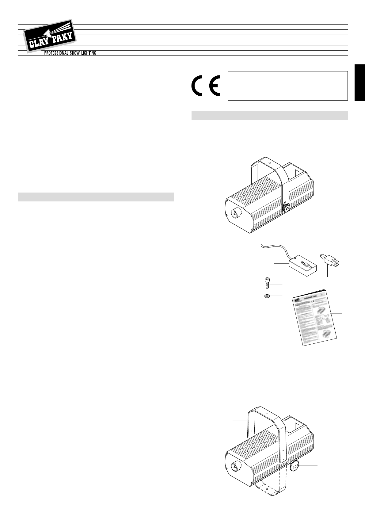
Unpacking
Open the cardboard box, take out the polystyrene wrapping and separate it,
freeing the projector.
Remove the plastic bag from the smoke machine and position this on a horizontal top.
5
GOLDEN FOG
ENGLISH
1000
2000
2000 DMX
®
INSTRUCTIONS MANUAL
Carefully read this instructions manual in its entirety and keep it safe for future
reference.
It is essential to know the information and comply with the instructions given
in this manual in order to ensure the fitting is installed, used and serviced correctly and safely.
CLAY PAKY S.p.A. disclaims all liability for damage to the fitting or to other
property or persons deriving from installation, use and maintenance that have
not been carried out in conformity with this instructions manual, which must
always accompany the fitting.
CLAY PAKY S.p.A. reserves the right to modify the characteristics stated in
this instructions manual at any time and without prior notice.
Congratulations on choosing a Clay Paky product! We thank you for your custom. Please note that this product, as all the others in the rich Clay Paky
range, has been designed and made with total quality to ensure excellent
performance and best meet your expectations and requirements.
•
Installation
Make sure all the parts for fixing the smoke machine are in a good state of repair.
Make sure the point of anchorage is stable before positioning the fitting.
•
Minimum distance of flammable materials
The fitting must be positioned so that any flammable materials are at least 1 metre
(3’ 3”) from every point on the surface of the fitting.
•
Direction and distance of the jet of smoke
Never turn the jet of smoke onto people or items that are flammable or can get
damaged or dirtied by the jet of smoke.
Installation above people is not permitted.
•
Maximum ambient temperature
For the fitting to operate well and reliably, the ambient temperature should not
exceed 35°C (95°F).
•
IP20 protection rating
The fitting is protected against penetration by solid bodies with a diameter of over
12mm (0,47”) (first digit 2), but not against dripping water, rain, splashes or jets of
water (second digit 0).
•
Protection against electrical shock
This fitting is classified, in accordance with the type of protection against electrical
shock, in Class I. It must therefore be connected to a power supply system with
efficient earthing.
It is, moreover, recommended to protect the supply lines of the projectors from indirect contact and/or shorting to earth by using appropriately sized residual current devices.
•
Hooking up to the supply mains
The operations for connecting to the electricity mains must be carried out by a
qualified electrical installer.
Check that the mains frequency and voltage correspond to the frequency and voltage for which the smoke machine is designed, given on the rear panel.
This panel also gives the input power. Refer to this to evaluate the maximum number of fittings to connect to the electricity line in order to avoid overloading.
•
Maintenance
Before starting any maintenance work or cleaning the fitting, cut off power from
the supply mains.
After switching off, do not touch the smoke nozzle for at least 1 hour to avoid
getting burnt.
•
Temperature of the external surface
The maximum temperature that can be reached on the external surface of the fitting, in a thermally steady state, is 60°C (140°F) except for on the smoke nozzle
where it reaches 300°C (572°F).
The products referred to in this manual conform to the European Community Directives to which they are subject:
• Low Voltage 73/23
• Electromagnetic Compatibility 89/336
SAFETY INFORMATION
1
UNPACKING AND PREPARATION
2
• Packing contents
Besides the smoke machine, the
packing also contains the following
accessories:
- Remote control (1) code
177034/801 (for GOLDEN FOG
1000 and 2000 models only).
- Socket for mounting on cable code 030210 (2).
- 2 screws (3) code 020002/029 (models 2000 and 2000 DMX only).
- 4 toothed washers (4) code
020201/005 (models 2000 and
2000 DMX only).
- This instructions manual code
099595 (5).
1
5
2
3
4
•
Projector mounting
GOLDEN FOG 1000
Position the bracket (6) according to the desired angle and lock it with the knobs
(7). The bracket (6) can be height adjusted by using the two holes on the bracket; it
can moreover also be mounted towards the bottom of the fitting. These last steps
require fully extracting the knobs (7), putting the bracket (6) back into the desired
position and reinserting the knobs (7), tightening them appropriately.
6
7
ENGLISH
Page 2
6
AUTO
256
128
64
32
4
16
8
1
2
START ADDRESS SELECT
ON
1
2
3
4
5
6
CHANNEL SELECT
1
4
8
FLUID
EMPTY
DATA
ERROR
PMX
DMX
SIGNAL
SCREEN
SIGNAL
RS232/423
(PMX)
1
2
3
45
SIGNAL
SCREEN
SIGNAL
54
3
2
1
DMX
512
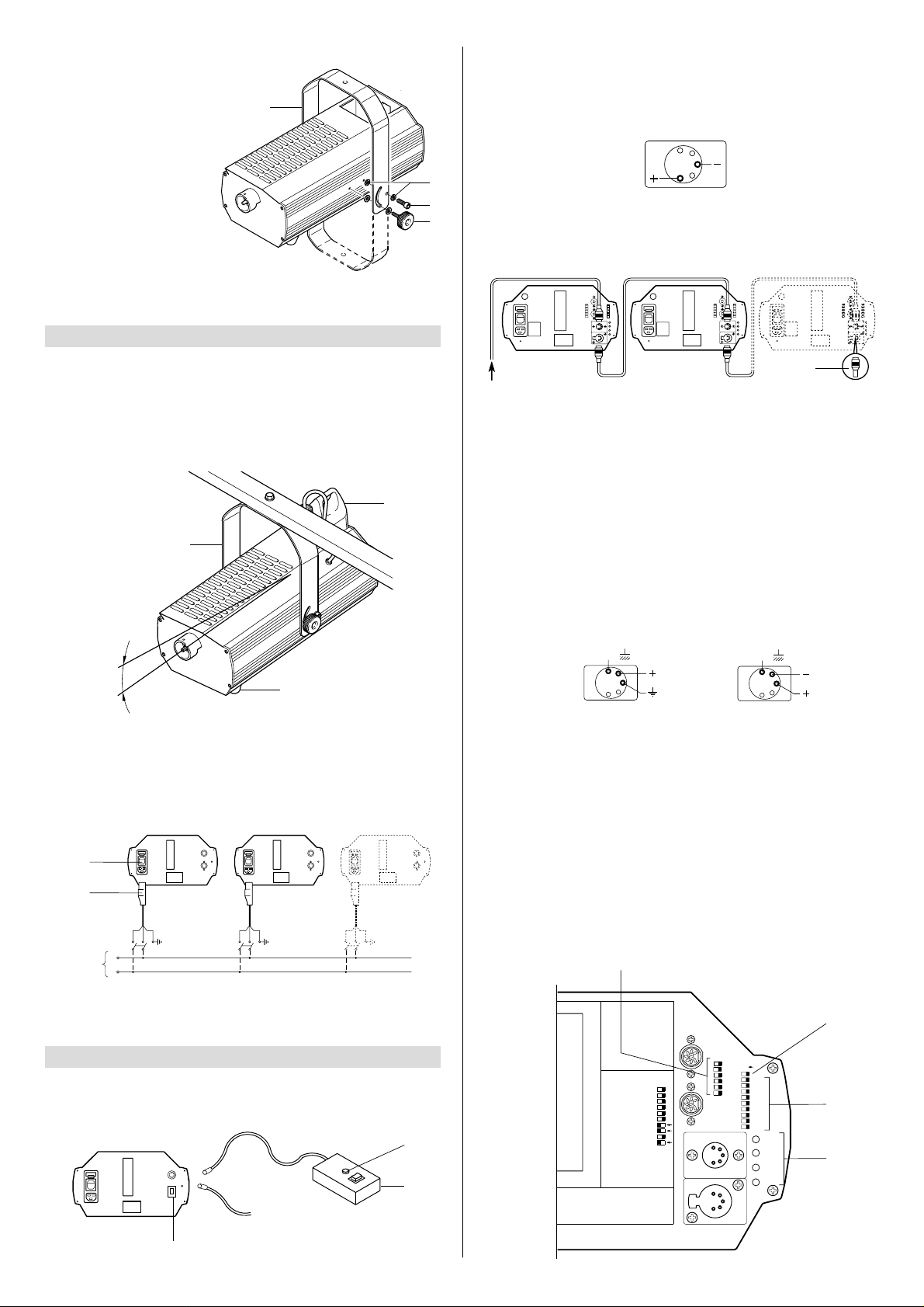
GOLDEN FOG 2000 and 2000 DMX
Secure the bracket (6) to the body
of the smoke machine with the aid
of the screws (3) and toothed washers (4) specially supplied, then
position the bracket (6) according
to the desired angle and lock it
with the knobs (7).
The bracket (6) can also be mounted towards the bottom of the fitting. To do this, it is necessary to
fully extract the knobs (7) and
screws (3), reposition the bracket
(6) as preferred, put the knobs (7)
and screws (3) back in, together
with the toothed washers (4), then
lock the bracket (6) with the appropriate angle.
•
Installing the fitting
The fitting needs to be installed horizontally, the angle the machine makes must
be no greater than 30° so that no liquid will come out of the tank (8).
The GOLDEN FOG smoke machine can be stood "on the floor" on its rubber feet
(9).
If the fitting is installed "on the ceiling" it must be secured using solely the specific
mounting (6), through the hole in the centre of it. Use a screw ø10mm with nut
and spring washer.
INSTALLATION
3
MAX. 30°
•
Mains power connection
Each fitting should be connected with its own switch so it can be switched on and
off individually from a distance.
The smoke machine has to be hooked up to the electricity mains via the specific
socket (2) supplied.
L
N
Mains
10
2
0-10V
1
12
11
GOLDEN FOG fittings are equipped with a switch with an indicator light (10) that
shows when the fitting is switched on.
GOLDEN FOG 1000 and 2000
0-10V analogue or remote control connection
CONNECTING CONTROL SIGNALS FOR
4
Smoke emission can be controlled by pressing button (11) on the rear panel of
the machine or the button on the low-voltage remote control (1) supplied with the
machine. The indicator light (12) on the remote control (1) warns that the boiler is
at temperature. It is also possible to control the fitting with a 0-10V analogue signal via a cable terminated with a Cannon 5-pin XLR plug.
54
3
2
1
GOLDEN FOG 2000 DMX
RS232/423(PMX)-DMX 512 connection
13
DMX 512
RS232/423
The connection between GOLDEN FOG 2000 DMX and the control unit and
between different fittings must be made with a cable in conformity with EIA RS485 specifications: braided, bipolar, shielded, 120Ω of characteristic impedance,
22-24 AWG, low capacity.
IMPORTANT: Do not use a microphone cable or any other cable with different
characteristics to the ones specified above.
IMPORTANT: The wires must make no contact with each other or with the metal
casing of the connectors. The casing needs to be connected to the braid of the
shield and to pin 1 of the connectors.
•
Fitting codes
Each GOLDEN FOG 2000 DMX occupies one control channel. For this to be correctly addressed to each fitting, it is necessary to code the machines.
This has to be done on each single smoke machine, switching the microswitches
(14) according to the following table. Coding can also be done with the machine
switched off.
16
14
17
15
The terminations need to be made with male/female connectors type XLR with 5
pins.
If you use the DMX signal it is necessary to give the last fitting a terminal plug
(13) with a resistance of 120Ω (minimum 1/4 W) between terminals 2 and 3.
If using the RS232/423(PMX) signal, the terminal is not required.
7
3
4
6
8
6
9
Page 3

7
Golden Fog 1 - Channels 01
ON
OFF
ON
OFF
ON
OFF
ON
OFF
ON
OFF
ON
OFF
ON
OFF
1
2
4
8
163264
128
256
TEST
OFF
ON
OFF
ON
CODE
ON
OFF
ON
OFF
ON
OFF
OFF
ON
Golden Fog 2 - Channels 02
Golden Fog 3 - Channels 03
Golden Fog 4 - Channels 04
Golden Fog 5 - Channels 05
Golden Fog 6 - Channels 06
Golden Fog 7 - Channels 07
Golden Fog 8 - Channels 08
Golden Fog 9 - Channels 09
Golden Fog 10 - Channels 10
Golden Fog 11 - Channels 11
Golden Fog 12 - Channels 12
0-10 V analogue connection with decoding
0-10V 0-10V 0-10V
Is
FOG
1
2
3
45
67
8
ANALOGUE
INPUTS 0 - 10 V
On the back of the GOLDEN FOG 2000 DMX there is a selector with 6 microswitches (15) that make it possible to control 6 fittings simultaneously on separate
channels, switching over the microswitches according to the following table.
Golden Fog
1
ON
OFF
ON
OFF
ON
OFF
ON
OFF
1
2
3
4
5
6
OFF
ON
OFF
ON
CODE
Golden Fog
2
Golden Fog
4
Golden Fog
3
Golden Fog
5
Golden Fog
6
•
Automatic operation
Turning the AUTO microswitch (16) onto ON puts the fitting onto automatic operation. Keeping the microswitch on this position, the frequency of the sprays of
smoke delivered depends on the level set on the DIL microswitches (14) normally used to select the address; there are therefore 512 possibilities for adjustment.
If automatic operation is activated, the four LEDs (17) on the rear panel come on
alternately from the bottom upwards.
When the machine is controlled via the control unit (AUTO microswitch on the
OFF position) the frequency of the sprays varies as the adjustment potentiometer moves forward.
After completing all the preliminary operations and installation, fill the tank with
smoke machine liquid, press the switch, wait for the boiler to reach temperature,
then check that smoke is generated and everything works properly.
IMPORTANT: Use solely CLAY PAKY smoke liquid in the light, medium and
heavy versions. Other types of fluid could impair the operation of the smoke machine and/or seriously damage some components.
On the rear panel of the GOLDEN FOG 2000 DMX model there is an indicator light (18 – “Fluid Empty”) to signal the liquid has finished.
USE
5
18
AUTO
256
128
64
32
4
16
8
1
2
START ADDRESS SELECT
ON
1
2
3
4
5
6
CHANNEL SELECT
1
4
8
FLUID
EMPTY
DATA
ERROR
PMX
DMX
•
Replacing fuses
To replace the fuses, press the tab
(19) and take out the fuse-holder box
(20). Replace blown fuses with new
ones of the type specified on the label
(21) on the fuse-holder box (20).
Put it back in so the tab (19) clicks home.
•
Periodical cleaning
Every time before use, clean any drops
of fluid off the outlet pipe (22).
Approximately every 1000 hours of
operation, have qualified personnel
check the machine.
MAINTENANCE
6
19
20
21
22
ENGLISH
5 AT
5x20
250 V
FUSE
200V 220V 240V
50 Hz 60 Hz
60 Hz
CODE
C.81005
SERIAL NUMBER
IF11153
Page 4

GOLDEN FOG 1000
GOLDEN FOG 2000 and 2000 DMX
8
TECHNICAL DATA
8
Power supply
•
200 - 240V 50/60Hz
Input power
•
GOLDEN FOG 1000: 1,000 VA
•
GOLDEN FOG 2000: 2,000 VA
•
GOLDEN FOG 2000 DMX: 2,000 VA
Tank capacity
•
GOLDEN FOG 1000: 1 litre
•
GOLDEN FOG 2000 and 2000DMX: 2 litres
Consumption and maximum delivery
•
GOLDEN FOG 1000: 27 g/min
•
GOLDEN FOG 2000: 55 g/min
•
GOLDEN FOG 2000 DMX: 46 g/min
Pre-heating time
•
GOLDEN FOG 1000:
5 min.÷ 5 min. 30 sec.
•
GOLDEN FOG 2000:
4 min.÷ 4 min. 30 sec.
• GOLDEN FOG
2000 DMX:
4 min.÷ 4 min. 30 sec.
Smoke delivery time
•
GOLDEN FOG 1000: continuous
•
GOLDEN FOG 2000: 60”/65”
•
GOLDEN FOG 2000 DMX: 30 sec. at
100%, continuous with adjustment
CONTROL SYSTEMS
•
GOLDEN FOG 1000 - 2000
- Manual control
- Remote manual control
- 0-10V analogue input
•
GOLDEN FOG 2000 DMX
- Serial digital input
RS232/423(PMX) or DMX512
- 0-10V analogue input
INDICATORS
•
GOLDEN FOG 1000 - 2000
- Machine ready indicator light
on remote control
- Power light
•
GOLDEN FOG 2000 DMX
- Power light
- Fluid finished indicator light
- Automatic operation
- DMX signal reception
- PMX signal reception
- Error in receiving signals
SAFETY DEVICES
Power supply automatically cut off in the
event of the boiler overheating.
Weight and dimensions
•
GOLDEN FOG 1000:
Weight 7.5 Kg (16 lbs 8 ozs)
•
GOLDEN FOG 2000:
Weight 11 Kg (24 lbs 3 ozs)
•
GOLDEN FOG 2000 DMX:
Weight 12 Kg (26 lbs 6 ozs)
A mm
270 (10.63”)
310 (12.20”)
B mm
490 (19.29”)
490 (19.29”)
C mm
230 (9.06”)
340 (13.39”)
No mains supply.
Check the supply socket
is powered and/or fuse
conductivity.
Signal transmission cable shortcircuited or disconnected.
Replace cables.
Cannon not properly inserted.
Insert the Cannon on the back
of the machine.
No liquid in tank. Fill the tank with liquid.
Internal mechanical part broken. Call an authorized technician.
Tube not inserted properly. Put the tube back into the tank.
Wrong address. Check the digital address.
Electronics broken. Call an authorized technician.
THE LED ON THE REMOTE CONTROL FAILS TO COME ON
THE FITTING WILL NOT SWITCH ON
NO SMOKE IS GENERATED
TROUBLE
THE TUBE FAILS TO DRAW LIQUID
IT FAILS TO WORK WITH DIGITAL SIGNALS
POSSIBLE CAUSES
CHECKS AND REMEDIES
•
•
•
•
•
•
•
•
TROUBLESHOOTING
7
A
B
C
 Loading...