

Page 1
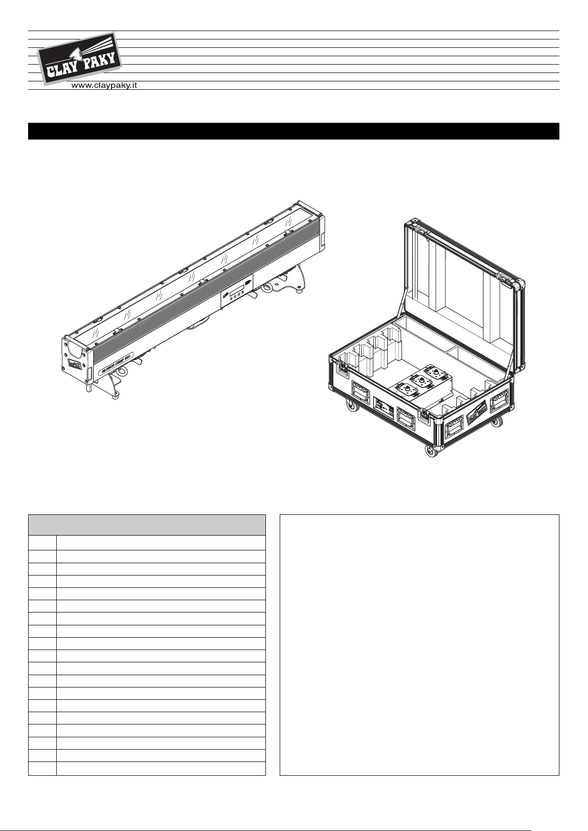
GLOW UP STRIP 100
®
ENGLISH
& FLIGHT CASE
C71080
F21250
INSTRUCTIONS MANUAL
Pag.
2
3
4
4
4
6
8
8
9
10
16
17
17
18
21
22
22
23
CONTENTS
Contents
Safety information GLOW UP STRIP 100
Safety information FLIGHT CASE
Unpacking and preparation
Removal of the protective film
Installation and start-up
Control panel
Shortcut keys menu
Button function
Preset colors for Stand Alone
Menu set
Operating Mode
RDM Controls implemented for GLOWUP series
Aerial
Maintenance
Optional accessories
Technical data
Cause and solution of problems
Channel functions
Congratulations on choosing a Clay Paky product!
We thank you for your choice. Please note that this product,
as all the others in the rich Clay Paky range, has been
designed and manufactured with total quality to ensure
excellent performance and best meet your expectations and
requirements.
Carefully read this instruction manual in its entirety and keep it
safe for future reference.
It is essential to know the information and comply with the
instructions given in this manual in order to ensure the fitting is
installed, used and serviced correctly and safely.
CLAY PAKY S.p.A. disclaims all liability for damage to the
fitting or to the other property or persons deriving from
installation, use and maintenance that have not been carried
out in conformity with this instructions manual, which must
always accompany the fitting.
CLAY PAKY S.p.A. reserves the right to modify the
characteristics stated in this instructions manual at any time and
without prior notice.
1
Page 2
0.2
90°C
AFETY INFORMATION GLOW UP STRIP 100
S
• Installation
Make sure all parts for fixing the projector are in a good state of repair. Make sure the point of
nchorage is stable before positioning the projector.
a
The safety chain must be properly hooked onto the fitting and secured to the framework, so that,
if the primary support system fails, the fitting falls as little as possible. If the safety chain gets used,
it needs to be replaced with a genuine spare.
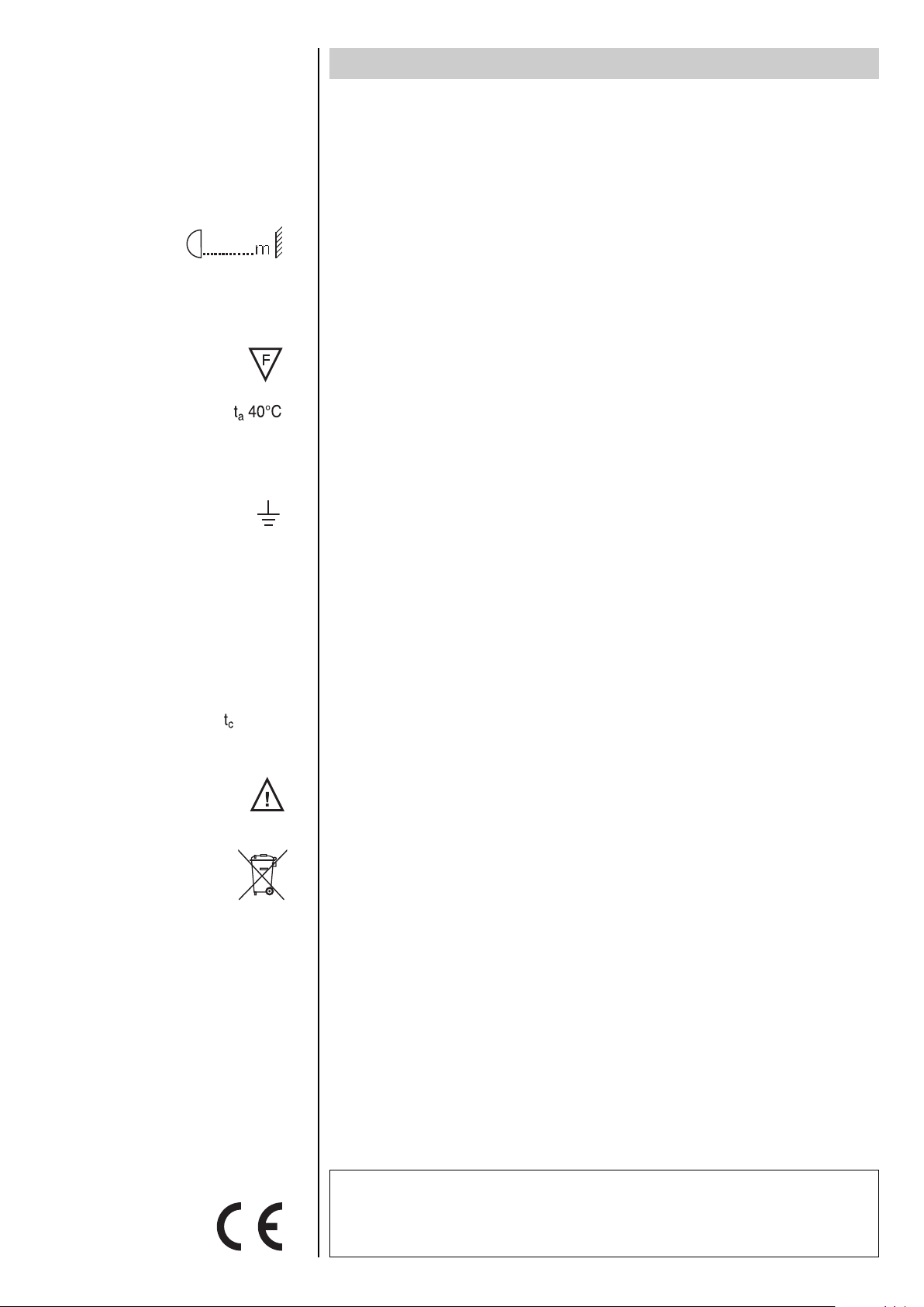
• Minimum distance of illuminated objects
The projector needs to be positioned so that the objects hit by the beam of light are at least 0.2
metres (8”) from the lens of the projector.
• Minimum distance from flammable materials
The projector must be positioned so that any flammable materials are at least 0.20 metres (8") from
very point on the surface of the fitting.
e
• Mounting surfaces
It is permissible to mount the fitting on normally flammable surfaces.
• Maximum ambient temperature
Do not use the project if ambient temperature (Ta) exceeds 40°C.
IP65
LiFePO4
• IP65 protection rating
The equipment is fully protected against dust (first digit 6) and against jets of water (second digit 5).
• Protection against electrical shock
Connection must be made to a power supply system fitted with efficient earthing (Class I appliance
according to standard EN 60598-1).
It is, moreover, recommended to protect the supply lines of the projectors from indirect contact
and/or shorting to earth by using appropriately sized residual current devices.
• Connection to the power mains
A qualified electrician must perform connection to the power mains.
Check that the mains frequency and voltage correspond to the frequency and voltage for which the
projector was designed and indicated on the electrical data label.
This label also gives the input power. Refer to the latter to evaluate the maximum number of
devices to be connected to the mains to avoid overloads.
• External surface temperature
The maximum temperature that can be reached on the external surface of the fitting, in a thermally
steady state, is 90°C (320°F).
• Maintenance
Before starting any maintenance work or cleaning the projector, cut off power from the supply
mains. After switching off, do not remove any parts of the fitting for at least 10 minutes. The lenses
must be mounted and, if visibly damaged, they have to be replaced with genuine spares.
• Battery
This product contains a lithium iron tetraphosphate rechargeable battery. To protect the
environment, please discard the battery at the end of its life cycle according to current law.
GLOW UP STRIP 100
The products to which this manual refers comply with the European Directives pursuant to:
• 2006/95/EC - Safety of electrical equipment supplied at low voltage (LVD)
• 2004/108/EC - Electromagnetic Compatibility (EMC)
• 2011/65/EU - Restriction of the use of certain hazardous substances (RoHS)
2
Page 3
<Nessuno(a)>
• Installation
Ensure that the Flight Case, when used for charging GLOW UP, is positioned at a distance of 15
m from any surface or wall, to allow proper ventilation.
c
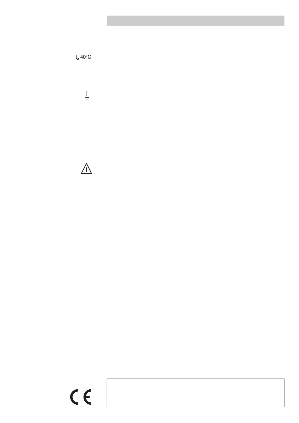
• Maximum ambient temperature
Do not operate the device if ambient temperature (Ta) exceeds 40°C.
AFETY INFORMATION FLIGHT CASE
S
IP20
• IP20 protection rating
The fitting is protected against penetration by solid bodies of over 12mm (0.47”) in diameter (first
digit 2), but not against dripping water, rain, splashes or jets of water (second digit 0).
Protection against electrical shock
•
onnection must be made to a power supply system fitted with efficient earthing (Class I appliance
C
according to standard EN 60598-1).
It is, moreover, recommended to protect the supply lines of the projectors from indirect contact
and/or shorting to earth by using appropriately sized residual current devices.
• Connection to the power mains
A qualified electrician must perform connection to the power mains.
Check that the mains frequency and voltage correspond to the frequency and voltage for which the
projector was designed and indicated on the electrical data label.
This label also gives the input power. Refer to the latter to evaluate the maximum number of
devices to be connected to the mains to avoid overloads.
• Maintenance
Before starting any maintenance work or cleaning, cut off power from the supply mains.
GLOW UP STRIP 100
The products to which this manual refers comply with the European Directives pursuant to:
• 2006/95/EC - Safety of electrical equipment supplied at low voltage (LVD)
• 2004/108/EC - Electromagnetic Compatibility (EMC)
• 2011/65/EU - Restriction of the use of certain hazardous substances (RoHS)
3
Page 4
2 x 183102/805
1
I
N
S
T
R
U
C
T
I
O
N
S
M
A
N
U
A
L
C
o
n
g
r
a
t
u
l
a
t
i
o
n
s
o
n
c
h
o
o
s
i
n
g
a
C
l
a
y
P
a
k
y
p
r
o
d
u
c
t
!
W
e
t
h
a
n
k
y
o
u
f
o
r
y
o
u
r
c
h
o
i
c
e
.
P
l
e
a
s
e
n
o
t
e
t
h
a
t
t
h
i
s
p
r
o
d
u
c
t
,
a
s
a
l
l
t
h
e
o
t
h
e
r
s
i
n
t
h
e
r
i
c
h
C
l
a
y
P
a
k
y
r
a
n
g
e
,
h
a
s
b
e
e
n
d
e
s
i
g
n
e
d
a
n
d
m
a
n
u
f
a
c
t
u
r
e
d
w
i
t
h
t
o
t
a
l
q
u
a
l
i
t
y
t
o
e
n
s
u
r
e
e
x
c
e
l
l
e
n
t
p
e
r
f
o
r
m
a
n
c
e
a
n
d
b
e
s
t
m
e
e
t
y
o
u
r
e
x
p
e
c
t
a
t
i
o
n
s
a
n
d
r
e
q
u
i
r
e
m
e
n
t
s
.
C
a
r
e
f
u
l
l
y
r
e
a
d
t
h
i
s
i
n
s
t
r
u
c
t
i
o
n
m
a
n
u
a
l
i
n
i
t
s
e
n
t
i
r
e
t
y
a
n
d
k
e
e
p
i
t
s
a
f
e
f
o
r
f
u
t
u
r
e
r
e
f
e
r
e
n
c
e
.
I
t
i
s
e
s
s
e
n
t
i
a
l
t
o
k
n
o
w
t
h
e
i
n
f
o
r
m
a
t
i
o
n
a
n
d
c
o
m
p
l
y
w
i
t
h
t
h
e
i
n
s
t
r
u
c
t
i
o
n
s
g
i
v
e
n
i
n
t
h
i
s
m
a
n
u
a
l
i
n
o
r
d
e
r
t
o
e
n
s
u
r
e
t
h
e
f
i
t
t
i
n
g
i
s
i
n
s
t
a
l
l
e
d
,
u
s
e
d
a
n
d
s
e
r
v
i
c
e
d
c
o
r
r
e
c
t
l
y
a
n
d
s
a
f
e
l
y
.
C
L
A
Y
P
A
K
Y
S
.
p
.
A
.
d
i
s
c
l
a
i
m
s
a
l
l
l
i
a
b
i
l
i
t
y
f
o
r
d
a
m
a
g
e
t
o
t
h
e
f
i
t
t
i
ng
o
r
t
o
t
h
e
o
t
h
e
r
p
r
o
p
e
r
t
y
o
r
p
e
r
s
o
n
s
d
e
r
i
v
i
n
g
f
r
o
m
i
n
s
t
a
l
l
a
t
i
o
n
,
u
s
e
a
n
d
m
a
i
n
t
e
n
a
n
c
e
t
h
a
t
h
a
v
e
n
o
t
b
e
e
n
c
a
r
r
i
e
d
o
u
t
i
n
c
o
n
f
o
r
m
i
t
y
w
i
t
h
t
h
i
s
i
n
s
t
r
u
c
t
i
o
n
s
m
a
n
u
a
l
,
w
h
i
c
h
m
u
s
t
a
l
w
a
y
s
a
c
c
o
m
p
a
n
y
t
h
e
f
i
t
t
i
n
g
.
C
L
A
Y
P
A
K
Y
S
.
p
.
A
.
r
e
s
e
r
v
e
s
t
h
e
r
i
g
h
t
t
o
m
o
d
i
f
y
t
h
e
c
h
a
r
a
c
t
e
r
i
s
t
i
c
s
s
t
a
t
e
d
i
n
t
h
i
s
i
n
s
t
r
u
c
t
i
o
n
s
m
a
n
u
a
l
a
t
a
n
y
t
i
m
e
a
n
d
w
i
t
h
o
u
t
p
r
i
o
r
n
o
t
i
c
e
.
G
L
O
W
U
P
S
T
R
I
P
1
0
0
&
F
L
I
G
H
T
C
A
S
E
C
7
1
0
8
0
®
E
N
G
L
I
S
H
C
O
N
T
E
N
T
S
P
a
g
e
2
3
4
4
5
6
8
8
9
1
0
1
5
1
6
1
7
1
9
2
0
2
0
2
1
C
o
n
t
e
n
t
s
S
a
f
e
t
y
i
n
f
o
r
m
a
t
i
o
n
G
L
O
W
U
P
S
a
f
e
t
y
i
n
f
o
r
m
a
t
i
o
n
F
L
I
G
H
T
C
A
S
E
U
n
p
a
c
k
i
n
g
a
n
d
p
r
e
p
a
r
a
t
i
o
n
R
e
m
o
v
a
l
o
f
t
h
e
p
r
o
t
e
c
t
i
v
e
f
i
l
m
I
n
s
t
a
l
l
a
t
i
o
n
a
n
d
s
t
a
r
t
-
u
p
C
o
n
t
r
o
l
p
a
n
e
l
S
h
o
r
t
c
u
t
k
e
y
s
m
e
n
u
B
u
t
t
o
n
f
u
n
c
t
i
o
n
P
r
e
s
e
t
c
o
l
o
r
s
f
o
r
S
t
a
n
d
A
l
o
n
e
“
G
L
O
W
U
P
C
”
M
a
i
n
m
e
n
u
O
p
e
r
a
t
i
n
g
M
o
d
e
M
a
n
u
a
l
z
o
o
m
-
A
e
r
i
a
l
M
a
i
n
t
e
n
a
n
c
e
O
p
t
i
o
n
a
l
a
c
c
e
s
s
o
r
i
e
s
T
e
c
h
n
i
c
a
l
d
a
t
a
C
a
u
s
e
a
n
d
s
o
l
u
t
i
o
n
o
f
p
r
o
b
l
e
m
s
C
h
a
n
n
e
l
f
u
n
c
t
i
o
n
s
1
1
2
2
2
3
3
m
a
x
9
0
°
2
1
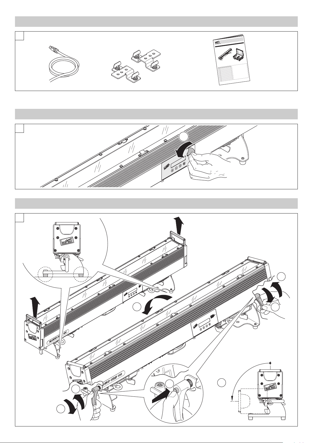
Packing content - Fig. 1
2
NPACKING AND PREPARATION
U
REMOVAL OF THE PROTECTIVE FILM
IST003/001
3
INSTALLATION AND START-UP
GLOW UP STRIP 100
4
Page 5
1
1
2
3
3
4
4
5
5
3
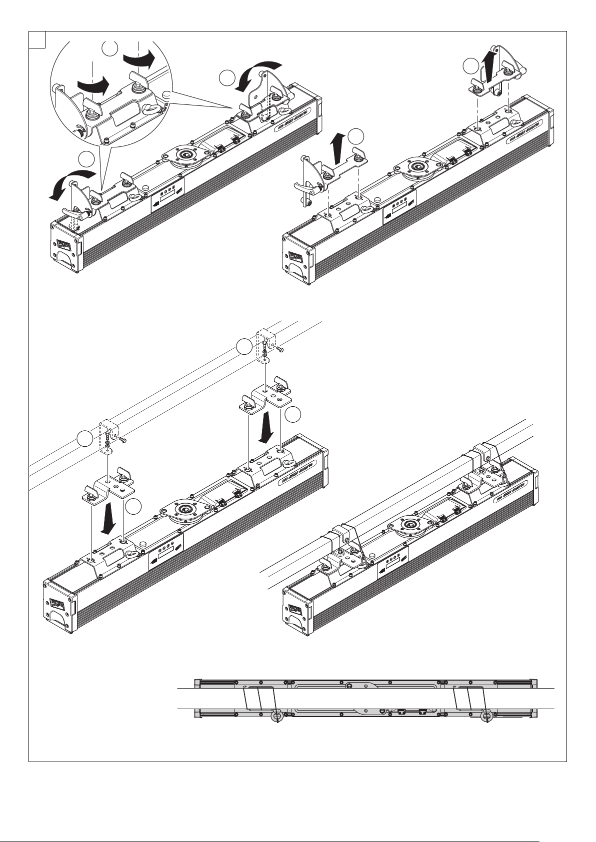
Projector installation - Fig. 3
The projector can be installed on the floor resting on specific rubber feet, on a truss, on the ceiling or wall.
WARNING: the safety chain must be installed except when the projector rests on the floor. (Code 105015/801 available upon request).
This must be secured to the projector support structure and then hooked to the fastening point at the centre of the base.
GLOW UP STRIP 100
5
Continued
➔
Page 6
DMX 51
2
DMX 5
12
5 PIN
2
3
1
1
2
3
4
4
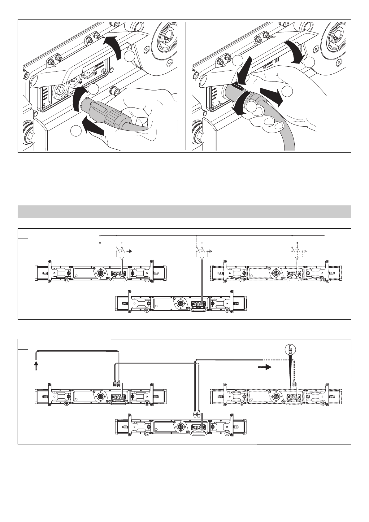
Connecting and disconnecting the power cord - Fig. 4
When connecting the power cord the user can choose whether to use the GLOW UP in one of the following ways:
1) Power cord connected for battery charge.
2) Power cord connected for projector power (thus bypassing battery operations).
The GLOW UP cannot work in both ways simultaneously.
5
Connections to the power mains - Fig. 5
Power Supply
6
CONTROL PANEL
Connections to the control signal line (DMX) - Fig. 6
Use a cable conforming to specifications EIA RS-485: 2-pole twisted, shielded, 120Ω characteristic impedance, 22-24 AWG, low capacity. Do not use
microphone cable or other cable with characteristics differing from those specified. End connections must be made using XLR type 3-pin male/female
connectors. A terminating plug must be inserted on the last projector with a resistance of 120 (minimum 1/4 W) between terminals 2 and 3.
IMPORTANT: The wires must not make contact with each other or with the metal casing of the connectors. The casing must be connected to the shield
braid and pin 1 of the connectors.
GLOW UP STRIP 100
6
Page 7
7
Switching on the projector - Fig. 7
The projector immediately turns on when the power cord is plugged in or, if used in battery mode, by pressing and holding down keys
several seconds.
and Sfor
A
Clay Paky GLOW UP STRIP 100 Address xxx BAT xx%
GLOW UP STRIP 100 Software release x.x x xxxxx ??? *
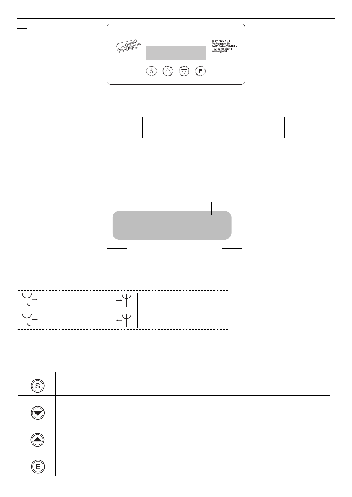
The control panel (Figure 8) has a display and buttons for complete programming and management of the projector menu.
The display can be in one of two conditions: idle status and settings status. When idle, the projector DMX address and percent battery charge are displayed.
If no button is pressed after a wait period (about 60 seconds) when in menu settings status, the display automatically returns to idle status. It should
be noted that when this condition occurs, any modified value that has not yet been confirmed with the
To turn off the GLOW UP, hold down keys
Press
When GLOW UP is in idle status the information page will appear on the display:
-Yes to turn off the GLOW UP or press S-NO to return to the settings menu.
A
DMX Address
Operating mode
(see page 15)
and Sfor several seconds. A confirmation message will appear (Switch off?).
A
ADDR 001 BAT 40%
DMX C
Yy
Link status
(Wireless or Wired)
W
Display symbology - (Link Status)
key will be cancelled.
A
Time or percent remaining
of the battery charge
Warning Radio
W42 (radio board not found)
W43 (radio board not interact)
If errors W42/W43 appear on the display,
do an RDM Discovery (see page 11) to
see if the error disappears. If it does not,
check the intactness of the wireless board.
* see pag. 7
Display symbology
Transmission to DMX cable
Reception from DMX cable
Initial projector address settings
An initial address must be set on each single project for the control signal. Address settings: see page 8 or 11.
Reception DMX from Radio (wireless)
Transmission DMX from Radio (wireless)
Button functions – Menu SET
SELECT
DOWN
UP
ENTER
• If pressed in idle status: Cyclically switches between idle status and menu settings.
• If pressed while setting a menu: Moves to an upper level without changing anything (exits the function)
Decreases the value displayed (with auto-repetitions), or passes to the next item on the menu
For quick access to the minimum parameter value, press the UP key while holding down the DOWN key.
Increases the value displayed (with auto-repetitions), or passes to the previous item on the menu
For quick access to the maximum parameter value, press the DOWN key while holding down the UP key.
Confirms the displayed value or activates the displayed function or opens the next menu.
GLOW UP STRIP 100
7
Page 8
BAT 40
%
??
SET
MOD
HORTCUT KEYS MENU
S
y pressing the ENTER
B
By pressing the ENTER
1) Use the UP
Unlink Transmitter – Disconnected from the transmitter
Link Receivers – Connected to all free receivers
Unlink Receiver – Disconnected from all receivers
Select Card (see page 11)
Config Card (see page 11)
) Press ENTER
2
previous Menu.
and DOWN Ckeys to select one of the following settings:
B
A
ey and UP
k
A
key and DOWN C, it is possible to assign the desired command to the GLOW UP Radio module:
A
o confirm the selection (the display blinks for several seconds) or SELECT
t
the DMX address setting function can be quickly accessed.
,
B
o keep the current settings and return to the
t
S
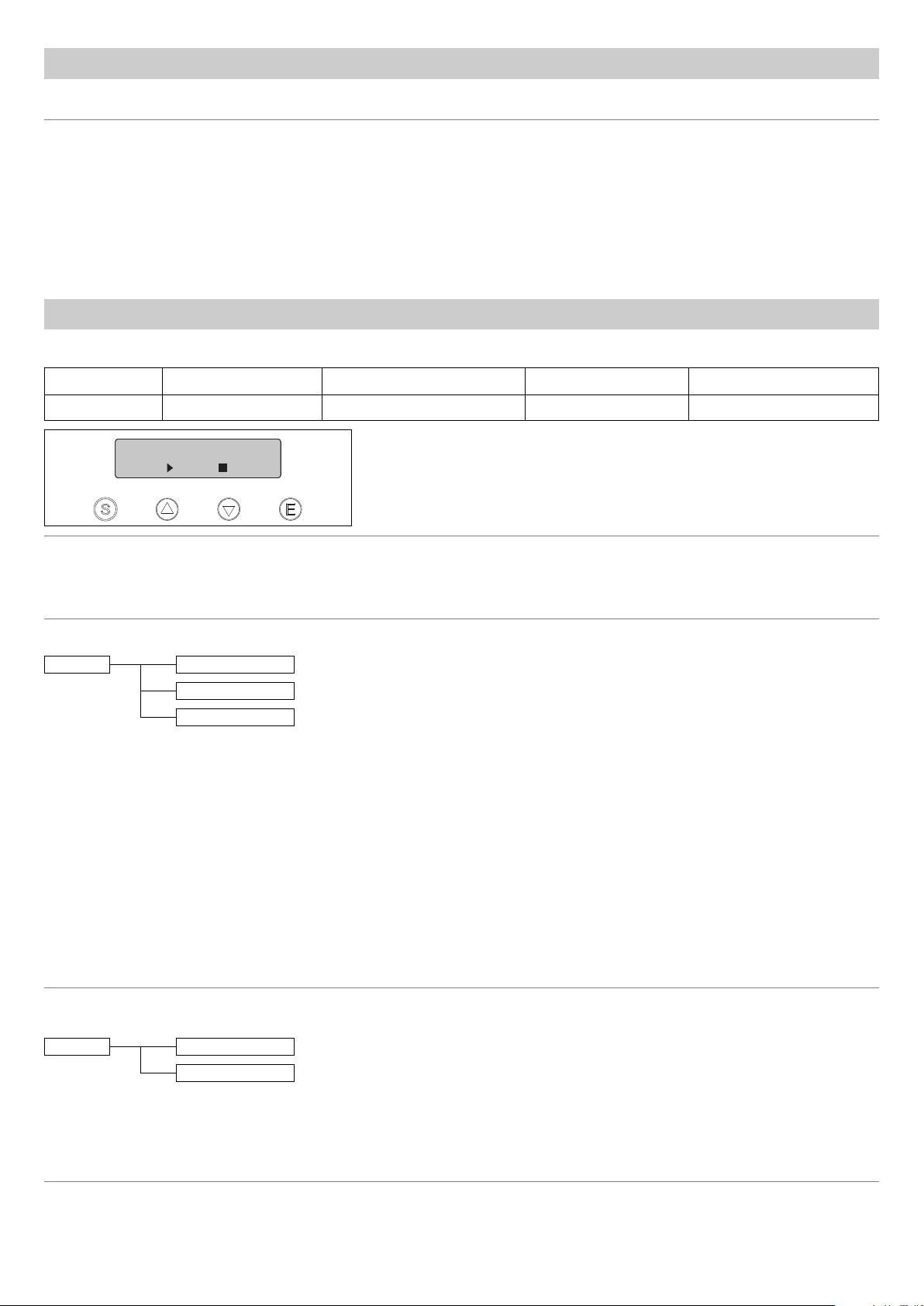
BUTTON FUNCTION
By pressing any button when GLOW UP is in idle status, the BUTTON FUNCTION menu is accessed.
Symbol SET or
Function Setting Play/Pause Stop Mode
Press SET SELECT
Program
DMX Address
Advanced (Menu use is recommended for qualified technical personnel.)
to access the menus (see page 9):
S
II
MOD
Press ENTER
Mode
Use the UPBe DOWN Ckeys to select the mode from those available:
Stand Alone / DMX – Press ENTER
may be chosen to be run locally and the DMX being inactive)
Master/Slave (The "Transmitter" transmits to the "Receivers" the default programme in PLAY) - Press ENTER
• Receiver enables established wired or wireless reception and reads channels, starting from channel DMX 1, without changing the pre-set DMX address.
• Transmitter enables established wired or wireless transmission, transmits starting from channel DMX 1, without changing the pre-set DMX address.
Master/Slave DMX Rec (The "Transmitter" transmits the DMX recording to the "Receivers") - Press ENTER E and select the mode from those available:
• Receiver enables established wired or wireless reception and reads channels, starting from the pre-set DMX address.
• Transmitter enables established wired or wireless transmission, transmits starting from the pre-set DMX address.
NOTE: in a GLOW UP series which is part of a battery, it is imperative to first select all the receivers and finally select the Transmitter.
II
PLAY/PAUSE UPBkey: activates or pauses a particular mode.
Play
MOD to select the GLOW UP operating mode
A
Stand Alone / DMX
Master / Slave
Master / Slave DMX Rec
to confirm (runs “Unlink Transmitter”, receives the DMX at the pre-set address; by using the PLAY key, a scene
A
Fixed Colours
Sequernces
and select the mode from those available:
A
By pressing the PLAY UP
Fixed Colours: it is possible to associate a bit value to each GLOW UP channel or you can select a color from the stored ones by accessing the Preset
Colors menu (see table on page 8). It is possible to mix Strobo and Dimmer with any preset color channel.
Sequence: it is possible to associate Speed and Fade of the pre-set Sequences (Preset 1,2,3)
button, the sub-menu can be accessed:
B
STOPDOWN Ckey: deactivates the active programme.
GLOW UP STRIP 100
8
Page 9

PRESET COLORS FOR STAND ALONE
Colour Reference
01 RGBW -0000
2 RED - 255 000
0
03 GREEN -0255 00
04 BLUE -00255 0
05 YELLOW - 255 255 00
06 CYAN -0250 185 0
07 MAGENTA - 255 0 140 0
08 WHITE -000100
09 ORANGE - 255 115 00
10 PINK - 127 00100
1 VIOLET - 255 0 184 200
1
12 AQUA - 85 255 105 0
13 SKY BLUE - 118 255 150 0
14 FULL WHITE - 255 255 255 255
15 COOL WHITE - 225 255 253 255
16 WARM WHITE - 255 255 220 255
17 WHITE 3200 - 255 176 0 255
18 WHITE 2500 - 255 99 0 255
19 YELLOW 2 LEE 101 133 145 00
20 STRAW LEE 103 255 255 0 240
21 ORANGE LEE 105 246 195 00
22 LIGHT ROSE LEE 107 218 00255
23 DARK PINK LEE 111 255 0 120 255
24 MAGENTA LEE 113 255 0 78 0
25 BLUE 2 LEE 115 0 255 175 0
26 MED BLUE GREEN LEE 116 0 255 160 0
27 DARK BLUE LEE 119 0 180 180 0
28 BRIGHT PINK LEE 128 255 0 141 95
29 MEDIUM BLUE LEE 132 0 255 200 0
30 GOLDEN AMBER LEE 134 255 175 0 25
31 DEEP GOLDEN AMBER LEE 135 255 140 0 25
32 PALE LAVENDER LEE 136 00100 190
33 APRICOT LEE 147 152 122 0 76
34 DARK LAVENDER LEE 180 0 114 144 112
35 CHOCOLATE LEE 156 238 189 0 227
36 JUST BLUE LEE 079 0 187 175 0
37 SURPRISE PINK LEE 194 78 00255
38 SCARLET LEE 024 255 0 58 113
39 SURPRISE PEACH LEE 017 145 00153
40 FIRE LEE 019 255 141 44 0
41 ENGLISH ROSE LEE 108 161 119 0 255
42 MAUVE LEE 126 255 0 208 150
43 BRIGHT BLUE LEE 141 0 255 186 37
44 ALICE BLUE ROSCO 378 0 255 223 140
45 ROSE INDIGO ROSCO 358 00255 133
46 URBAN BLUE ROSCO 081 0 255 187 35
47 COOL BLUE ROSCO 066 0 255 148 153
48 LIGHT SALMON ROSCO 030 255 112 0 162
49 MAYAN SUN ROSCO 318 150 114 0 162
50 CHERRY ROSE ROSCO 332 255 0 92 0
51 FLESH PINK ROSCO 034 255 0 132 255
52
SKELTON EXOTIC SANGRIA
ROSCO 039 255 0 180 100
RGBW
Bit value
GLOW UP STRIP 100
9
Page 10

ENU SET
M
1
dit scene
rogram
P
E
E
equence
S
DMX
ecorder
r
dit
2
DMX
ddress
A
3
Advanced Setup Radio
MX
D
ode
M
ock
L
ption
O
uto Switch
A
ff option
O
ed
L
Control
Led
Current
Battery
Power
Power
Mode
isplay
D
Contrast
harging
C
nswer
a
Informations
Reset
Battery
Display
Fixture ID
Appl. UploadFW Uploader
Boot. Upload
Charge
BAT hour
Discharge
BAT hour
Battery
Monitor
LED
temperature
Total LED
hours
System
version
DMX Monitor
Reset
to SLV W
GLOW UP STRIP 100
Reset to
DMX W
Factory
Reset
CPU Reset
Test
10
Page 11

PROGRAM MENU
Program Edit scene
dit
E
Sequence
DMX
ecorder
r
Memory 1
...
..
.
Memory 10
Add step
Delete step
odify step
M
Scene
Speed
ade
F
EDIT SCENE
To create/overwrite/modify a SCENE customised by the user:
) Press ENTER
1
2) Use the UP
SCENES.
3) Press ENTER
4) A value can be associated with each GLOW UP channel inside each
SCENE using the UP
5) When finished with settings, press SELECT
message appears: SAVE SCENE X ?.
6) Press ENTER
eturn to the previous menu.
r
EDIT SEQUENCE
Allows you to create a sequence, made up of a series of SCENES saved
by the user.
1) Press ENTER
2) Use the UP
MEMORIES available.
3) Press ENTER
4) Press ENTER
STEPS with SCENE/SPEED/FADE as required.
5) Press ENTER
the previous Menu.
DMX RECORDER
To record a scene sequence programmed on the unit.
The projector must be set to Slave --> Receiver in order to accept a
recording. Press ENTER
ENTER
data (DMX waiting ...).
On completing the recording, press ENTER
press SELECT
again. GLOW UP is now ready to store control unit DMX
A
SCENE 1 appears on the display.
–
A
and DOWN Ckeys to select from the ten available
B
to open a SCENE.
A
and DOWN Ckeys.
B
to confirm and save the SCENE or SELECT Sto
A
– MEMORY 1 appears on the display.
A
and DOWN
B
to access the MEMORY
A
to access the MEMORY and add/delete/modify
A
to confirm the selection or SELECT Sto return to
A
A
Esc.
S
keys to select one of the ten
C
and reset the "Memory" by pressing
. A confirmation
S
to save, otherwise
A
DMX
Address
Advanced
Code
1234
Setup
Radio
DMX ADDRESS MENU
DMX ADDRESS
Allows the user to set the DMX address to be assigned to the projector.
1) Press ENTER
2) Use the UP
3) Press ENTER
several seconds) or SELECT
return to the previous Menu.
– the current DMX address appears on the display.
A
and DOWN Ckeys to set the DMX address.
B
to confirm the selection (the display blinks for
A
to keep the current settings and
S
ADVANCED MENU
To enable the "Advanced Menu" set up the "Access code" (1234) using the
UP
, DOWN C, RIGHT Ekeys.
B
Press
RADIO
Assigns the desired command to the GLOW UP Radio module Radio.
1) Press ENTER
2) Use the UP
3) Press ENTER
- "Menu advanced" appears on the display
F
– current settings appear on the display.
A
and DOWN Ckeys to select one of the following settings:
Unlink Trasmitter – Disconnected from the transmitter
Link Receivers – Connected to all free receivers
Unlink Receiver – Disconnected from all receivers
Select Card – it allows you to select the type of Radio card that is
installed or to be installed between the 2 available LM card and WS card
Config. Card
Tx mode – allows the user to select either the G3 or G4 transmission
channels. Press ENTER
to select one of the two available channels.
RDM discovery – to be used only when the wireless card is replaced;
press ENTER
several seconds) or SELECT
return to the previous Menu.
B
and use the UP Be DOWN Ckeys
A
to start the automatic search option.
A
to confirm the selection (the display blinks for
A
to keep the current settings and
S
GLOW UP STRIP 100
11
Continued
➔
Page 12

dvanced
A
S
etup
MX
D
ode
M
DMX MODE
Assigns the desired command to the GLOW UP Radio module
1) Press ENTER
2) Use the UP
settings:
SLAVE PRIORITY: GLOW UP runs as a Slave
•
ress ENTER
P
he DMX signal reception priority in case of conflict between the cable
t
nd wireless signals
a
Cable (default)
•
• Wireless
Press ENTER
several seconds) or SELECT
return to the previous Menu.
• MASTER OUTPUT: GLOW UP runs as a Master
Press ENTER
how the DMX signal should be sent to other devices:
Cable+Wireless
Cable
Wireless
Press ENTER
several seconds) or SELECT
return to the previous Menu.
• REPEATER: GLOW UP runs as a repeater
Press ENTER
how to run GLOW UP as a repeater: :
Direction – Press ENTER
keys to select whether the repeater should transmit the DMX signal from:
-Wireless to Cable
-Cable to Wireless
Press ENTER
several seconds) or SELECT
return to the previous Menu.
– current settings appear on the display.
A
and DOWN Ckeys to select one of the following
B
nd use the UP
a
A
to confirm the selection (the display blinks for
A
S
and use the UP Band DOWN Ckeys to select
A
to confirm the selection (the display blinks for
A
S
and use the UP Band DOWN Ckeys to select
A
again and use the UP Band DOWN
A
to confirm the selection (the display blinks for
A
S
nd DOWN
a
B
to keep the current settings and
to keep the current settings and
to keep the current settings and
C
k
eys to select
C
Lock
Option
Function– Press ENTER
keys to select whether the repeater should run from:
C
- Repeat & Play (GLOW UP repeats and plays)
- Repeat Only (GLOW UP operates in repeat mode only)
Press ENTER
several seconds) or SELECT
return to the previous Menu.
Enable/Disable
Press ENTER
several seconds) or SELECT
return to the previous Menu.
LOCK OPTION
It lets you assign a lock password, requested at each projector start up.
The same password can be used to access the "Menu Advanced".
1) Press ENTER
OFF the password request at start up.
- Select ON to enable. The previously entered password is displayed
and the desired numerical password can be entered with the UP
e DOWN Cand ENTER Akeys.
- By selecting OFF, no password will be requested at projector start up.
2) Access the Set Password menu and use the UP
ENTER
A
to confirm the selection (the display blinks for
A
to confirm the selection (the display blinks for
A
and access the Lock menu to enable ON or disable
A
keys to assign the desired Password number.
again and use the UP Band DOWN
A
to keep the current settings and
S
to keep the current settings and
S
, DOWN Cand
B
B
GLOW UP STRIP 100
Auto Switch
Off
AUTO SWITCH-OFF OPTION
Lets you enable G.U.S. 100 shutdown in the event of disuse for more than
4h, when battery powered.
1) Premere ENTER
2) Con i tasti UP
3) Press ENTER
seconds) or SELECT
previous Menu.
12
sul display appare l'impostazione corrente.
A
e DOWN C, abilitare ON o disabilitare OFF l'opzione.
B
to confirm the selection (the display blinks for several
A
to keep the current settings and return to the
S
Page 13

dvanced
A
S
etup
C
ed
L
ontrol
LED CONTROL
It allows you to select the operating mode of the GLOW UP Strip 100
between the two available:
1) Press ENTER
2) Use the UP
Common Mode: all LEDS are on simultaneously (page 22)
Single Mode: The LEDS are divided into 2 sets of 5 LEDS each (page 23).
Press ENTER
seconds) or SELECT
previous Menu.
– the current setting appears on the display.
A
and DOWN Ckeys to select one of the following settings:
B
to confirm the selection (the display blinks for several
A
to keep the current settings and return to the
S
ed
L
Current
Battery
Power
Power
Mode
Battery
Mode
owerCon
P
Mode
LED CURRENT
This allows you to set an operating current value for the Glow UP Strip 100
LED, whether it is running in Battery or PowerCon mode.
1) Press ENTER
on the screen.
2) Use the UP
3) Press ENTER
4) Use the UP
to associate different values depending on the selected operating mode,
(Battery Mode default: 700ma / PowerCon Mode default: 1000mA).
5) Press ENTER
previous Menu.
BATTERY POWER
It allows you to assign a maximum battery charge power (default 50%).
The higher the assigned percentage, the lower the battery charge duration
and vice versa.
1) Press ENTER
2) Use the UP
percentage to be attributed (minimum value 40%).
Press ENTER E to confirm the selection (the display blinks for several
seconds) or SELECT
previous Menu.
POWER MODE
Lets you select the set G.U.S. 100 power type.
1) Press ENTER – current settings appear on the display.
2) Use the UP and DOWN keys to select one of the 3 following options:
AC Mode: only runs with mains power, in the event of power outage, the
G.U.S. 100 turns off.
BATTERY Mode: directly battery powered when turned on without
mains power; if mains power is on or connected later, it automatically
charges to 100% maximum charge and then stops charging; if mains
power is turned off, it turns off (as with flight case).
MIXED Mode (default): mixed operations, as per first firmware release.
3) Press ENTER to confirm the selection (the display blinks for several
seconds) or SELECT to keep the current settings and return to the
previous Menu.
– BATTERY MODE / POWERCON MODE appears
A
and DOWN Cbuttons to select one of the 2 options.
B
.
A
and DOWN Cto select 700mA or 1000mA, it is possible
B
to confirm or press SELECT Sto return to the
A
– the current setting appears on the display.
A
and DOWN Ckeys to increase or decrease the
B
to keep the current settings and return to the
S
GLOW UP STRIP 100
Display
Contrast
DISPLAY
Allows you to dim the display backlight 60 seconds after switching to idle
status. To turn it back on, simply press any key.
1) Press ENTER
2) Use the UP
3) Press ENTER
several seconds) or SELECT
return to the previous Menu.
CONTRAST
Lets the user modify display contrast.
1) Press ENTER
2) Use the UP
according to the desired contrast.
3) Press SELECT
13
– current settings appear on the display.
A
and DOWN Ckeys to turn display backlight OFF or ON.
B
to confirm the selection (the display blinks for
A
to keep the current settings and
S
– current settings appear on the display.
A
and DOWN Ckeys to modify the value from 0 to 10
B
to return to the previous Menu.
S
Continued
➔
Page 14

dvanced
A
S
etup
harging
C
nswer
A
CHARGING ANSWER
This allows a default answer can be assigned for the battery charging
equest, when the GlowUp Strip is powered by the relative power cable
r
(powercon):
- On selecting YES, it will automatically switch to the powered by battery
status 1 minute after the GlowUp Strip cord is connected to the mains.
- On selecting NO, it will automatically switch to the powered by cable
tatus (excluding the battery mode) 1 minute after the GlowUp Strip
s
cord is connected to the mains.
FW Uploader
Battery
isplay
D
Fixture ID
Appl. Upload
Boot. Upload
BATTERY DISPLAY
Allows you to select how to display the battery charge in idle status.
) Press ENTER
1
2) Use the UP
options:
Automatic: displays the remaining battery charge in hours or as a
percentage.
ercentual: displays the percentage of remaining battery charge.
P
Time left: displays the remaining time of the battery charge in hours.
3) Press ENTER
several seconds) or SELECT
return to the previous Menu.
FIXTURE ID
Allows you to display the GLOW UP ID address.
1) Press ENTER
FW UPLOADER
Used to transfer software (Application o Boot) from one projector to all
other connected projectors.
1) Press ENTER
Cable upload: to start the firmware upload via DMX cable.
Radio upload: to start the firmware upload via wireless
2) Press ENTER
previous Menu.
current settings appear on the display.
–
A
and DOWN Ckeys to select one of the 3 following
B
to confirm the selection (the display blinks for
A
– the ID address appears on the display.
A
use the UP() e DOWN() keys to select:
A
to transfer firmware or SELECTSto return to the
A
to keep the current settings and
S
Informations
Charge BAT
hour
Discharge
BAT hour
Battery
Monitor
LED
temperature
CHARGE BATTERY HOURS
This option allows the user to view the total number of battery load hours
from construction to today.
1) Press ENTERA– total charge hours appear on the display.
2) Press SELECT
DISCHARGE BATTERY HOURS
Displays total GLOW UP battery powered operating hours from last time
used, from construction to today.
1) Press ENTER
the display.
2) Press SELECT
BATTERY MONITOR
Press the ENTER
status of the battery.
LED TEMPERATURE
Displays the LED working temperature.
1) Press ENTER
Temperature (real-time LED temperature)
Max Temperature (maximum temperature measured on LEDs)
2) Use the UP
temperature items to be displayed.
3) Press ENTER
menu.
To reset the “Max Temperature” value, simultaneously press and hold
down the UP
(Reset) appears, confirm by pressing ENTER
B
to return to the previous Menu.
S
– total battery powered operating hours appear on
A
to return to the previous Menu.
S
key on the display to view the voltage and current
A
– two options appear on the display:
A
and DOWN Ckeys to select which of the two
B
to display or SELECTSto return to the previous
A
and DOWN Ckeys for several seconds. When “Rst?”
.
A
GLOW UP STRIP 100
14
Page 15

dvanced
A
nformations
I
otal LED
T
hours
ystem
S
version
TOTAL LED HOURS
Displays total LED working hours, from construction to today.
1) Press ENTER
2) Press SELECT
YSTEM VERSION
S
Displays the version of the firmware loaded on the CPU board.
1) Press ENTER
Application release
Boot release (Backup Software)
2) Use the UP
firmware version items to be displayed.
3) Press ENTER
4) Press SELECT
– total LED working hours appear on the display.
A
to return to the previous Menu.
S
– two options appear on the display:
A
and DOWN Ckeys to select which of the two
B
– the release appears on the display.
A
to return to the previous Menu.
S
R
eset
MX
D
onitor
M
Reset to
LV W
S
DMX MONITOR
Displays the DMX input level in bit for each GLOW UP channel.
1) Press ENTER
2) Use the
3) Press ENTER
4) Press SELECT
RESET TO SLAVE WIRELESS
Resets GLOW UP and automatically sets the SLAVE WIRELESS settings.
1) Press ENTER
2) Press ENTER
Default after reset:
“Master Output”-> "Cable + Wireless"
"Repeater"-> "Disable"
"Repeater"-> "Function"->"Repeat & Play"
"Repeater"-> "Direction"->"Wirel. to Cable"
“DMX address” = 1
"Display"-> Off
“Contrast” = 5
“MOD”-> "Master/Slave" -> ”Receiver”
"Slave Priority"-> "Wireless
"Power Mode" -> ''Mixed Mode''
''Auto SwitchOff Opt. -> ''On''
B
and 255).
(OK?)
Menu.
– the first channel appears on the display.
A
and DOWN Ckeys to select the channel.
to display the channel DMX level (value between 0
A
to return to the previous Menu.
S
– a confirmation message appears on the display
A
to RESET or SELECT Sto return to the previous
A
GLOW UP STRIP 100
Reset to
DMX W
RESET TO DMX WIRELESS
Resets GLOW UP and automatically sets the DMX WIRELESS settings.
1) Press ENTER
(OK?)
2) Press ENTER
Menu.
Default after reset:
“Master Output”-> "Cable + Wireless"
"Repeater"-> "Disable"
"Repeater"-> "Function"->"Repeat & Play"
"Repeater"-> "Direction"->"Wirel. to Cable"
“DMX address” = 1
"Display"-> Off
“Contrast” = 5
“MOD”-> "Stand Alone/DMX"
"Power Mode" -> ''Mixed Mode''
''Auto SwitchOff Opt. -> ''On''
15
– a confirmation message appears on the display
A
to RESET or SELECT Sto return to the previous
A
Page 16

dvanced
A
R
eset
actory
F
eset
R
FACTORY RESET
Resets GLOW UP and automatically sets the Factory Default settings.
1) Press ENTER
(OK?)
2) Press ENTER
Menu.
Default after reset:
“Master Output”-> "Cable + Wireless"
"Repeater"-> "Disable"
"Repeater"-> "Function"->"Repeat & Play"
"Repeater"-> "Direction"->"Wirel. to Cable"
‘’DMX address’’ = 1
"Display"-> Off
“Contrast” = 5
“MOD”-> "Stand Alone/DMX"
"Slave Priority"-> "Cable"
"Led Current -> Battery Mode: 700mA / PowerCon Mode: 1000mA
"Power Mode" -> ''Mixed Mode''
''Auto SwitchOff Opt. -> ''On''
– a confirmation message appears on the display
A
to RESET or SELECT Sto return to the previous
A
CPU
Reset
est
T
CPU RESET
Used to reset the CPU. Settings will not be reset.
1) Press ENTER
(OK?)
2) Press ENTER
Menu.
TEST
Used to test the correct operations of effects.
1) Press ENTER
2) Use the
3) Press ENTER
S
B
to keep current settings.
– a confirmation message appears on the display
A
to RESET or SELECTSto return to the previous
A
.
A
and DOWN Ckeys to select the Test function.
to confirm the select and start the TEST or SELECT
A
GLOW UP STRIP 100
16
Page 17

OPERATING MODES
NOTE: the Wireless board is not two-way, therefore the following functions are excluded:
1) Repeater from Wireless to Wireless.
2) Receiving and transmitting wireless at the same time.
Operating Mode Slave Priority Repeater Master Output Display
Stand Alone / DMX in play/pause - Off - PLAY (o PAUSE)
- Wireless to Cable + Repeat &Play - PLAYW→C (o PAUSW→C)
-
- Wireless to Cable + Repeater only -W→C
- Cable to Wireless + Repeater only -C→W
Stand Alone / DMX in stop Cable Off - DMX C
Wireless Off - DMX W
- Wireless to Cable + Repeat &Play - DMXW→C
- Cable to Wireless + Repeat &Play - DMXC→W
- Wireless to Cable + Repeater only -W→C
- Cable to Wireless + Repeater only -C→W
Master Slave Tx (master addr 1) --Cable MAST C
--Wireless MAST W
--Cable+Wireless MAST CW
Master Slave Rx (slave addr 1) Cable Off - SLV C
(Play disabled) Wireless Off - SLV W
- Wireless to Cable + Repeat &Play - SLV W→C
- Cable to Wireless + Repeat &Play - SLV C→W
- Wireless to Cable + Repeater only -W→C
- Cable to Wireless + Repeater only -C→W
DMX Memory Tx (master all addr) --Cable MMTX C
--Wireless MMTX W
--Cable+Wireless MMTX CW
DMX Memory Rx (slave addr N) Cable Off - MMRX C
(Play disabled) Wireless Off - MMRX W
- Wireless to Cable + Repeat &Play - MMRX W→C
- Cable to Wireless + Repeat &Play - MMRX C→W
- Wireless to Cable + Repeater only -W→C
Cable to Wireless + Repeat & Play - PLAYC→W (o PAUSC→W)
GLOW UP STRIP 100
- Cable to Wireless + Repeater only -C→W
17
Page 18

DM CONTROLS IMPLEMENTED FOR GLOWUP SERIES
R
Control PID GET SET Description controller side
DEVICE_INFO 0x0060 X
IDENTIFY_DEVICE 0x1000 X
DMX_START_ADDRESS 0x00F0 XX
SOFTWARE_VERSION_LABEL 0x00C0 X
SUPPORTED_PARAMETERS 0x0050 X
PARAMETER_DESCRIPTION 0x0051 X
DMX_PERSONALITY 0x00E0 XX
DMX_PERSONALITY_DESCRIPTION 0x00E1 X
MANUFACTURER_LABEL 0x0081 X
DEVICE_LABEL 0x0082 XX
SENSOR_DEFINITION 0x0200 X
SENSOR_VALUE 0x0201 X
RECORD_SENSORS 0x0202 X
DEVICE_MODEL_DESCRIPTION 0x0080 X
Gathers information from the device
Makes the red leds on the addressed device pulse
Reads or sets the DMX address
Reads the firmware version
athers the PIDS on the non-basic controls
G
Gathers information on the controls related to the manufacturer
Reads or sets the channel mode
Reads the description of the channel mode
Reads the manufacturer name
Reads or writes a label on the device
Reads the description of the sensors present
Reads the level of the led temperature sensor
Saves the current temperature level
Reads the text description of the model
8
AERIAL
Aerial
GLOW UP STRIP 100
NOTES: To achieve best wireless
performance, it is recommended to
position GLOW UP with the aerial side
facing the transmitter, when possible.
18
Page 19

1
2
3
5
4
90°
1
2
Fuse 6,3x32mm
2.5AT 250Vac
(FUS000)
Fuse 6,3x32mm
10AT 250Vac
(030470)
9
AINTENANCE
M
Charging GLOW UP - Fig. 9
From 1 to 4 GLOW UPs can be simultaneously charged by appropriately connecting and powering the flight-case.
10
Replacing flight case fuses - Fig. 10
Each flight-case has 2 fuses associated with the main power cord connection and one fuse for each GLOW UP charge station.
GLOW UP STRIP 100
19
Page 20

1
2
3
3
2
3
2
3
1
11
Battery removal - Fig. 11
This product contains lithium iron tetraphosphate rechargeable battery. To protect the environment, please discard the battery at the end
of its working life according to current law.
LiFePO4
GLOW UP STRIP 100
Notes on how to achieve correct battery operations
1) Do not tamper with the control electronic circuit, do not tamper with the battery, do not short-circuit the battery.
2) Do not reuse GLOW UP after self-switch off as this indicates a low battery; recharge GLOW UP before using it again.
3) Do not leave the battery completely flat for over 5 days.
4) When not in use, recharge the battery at least every 4 months.
20
Continued
➔
Page 21

12
C61460
C61461
Parts requiring frequent cleaning.
Periodic cleaning - Fig. 12
To ensure optimal operation and performance for a long time it is essential to periodically clean the parts subject to dust and grease deposits. The
frequency with which the following operations are to be carried out depends on various factors such as wear and the work environment quality (air
humidity, dust, salinity, etc.). To remove dirt from external parts, use a soft cloth dampened with any liquid glass cleaning detergent.
It is recommended that the projector undergoes an annual service by a qualified technician for special maintenance involving at least the following
operations:
• General cleaning of internal parts.
• General visual check of internal parts, cabling, mechanical parts, etc.
• Electrical, photometric and functional checks; eventual repairs.
13
OPTIONAL ACCESSORIES
C61460 - longitudinal elliptic diffuser
C61461 - cross elliptic diffuser
GLOW UP STRIP 100
21
Page 22

230
(9.06")
170
(6.69")
115
(4.53")
130
(5.12")
1000
(39.37")
ECHNICAL DATA
T
Source
10x LED RGBW Ostar (OSRAM)
Led pilot power
100W
Total output
Max 3400 lumens
Optics
lectronically controlled optic zoom
E
LED color temperature
6000K
Head adjustment
0 - 90°
Cooling
Natural Convection
Control
• Wireless DMX multimode: Master, Slave and
Repeater
• Antenna built in the case IP65
• Master: can transmit other slaves the synchronised DMX scenes saved on it, both as macros
and as DMX recorder.
• Repeater: Receives the signal from the master
and re-transmits it to other Slaves hidden from
the master
• XLR 5-pole DMX-in DMX-out standard sockets
• Default macros, user programmable macros.
• DMX recorder to save scene sequences.
User interface
• LCD display 2 lines with 16 characters each,
backlit LED, white on black
4 membrane buttons
•
External power
Full range 100-240V 50-60Hz, PowerCon connector, for both battery charge and normal operations
Input Power
• 200 VA GLOW UP STRIP 100
• 650 VA Flight Case
Body
• Body extruded in black anodized aluminium
• 2 carrying handles
• 4 non-slip rubber feet
Fittings
4 fast-look holes for omega hook-up
Safety
Eyebolts for safety cables
Weight
15 Kg
Protection rating
IP65
Valves
ompensation valve IP65
C
Battery
• Duration 5 hours full
• Carica da Flight Case o con PowerCon
• More than 2000 charge/deplete cycles
• No memory effect
• No acid leaks
Working position
Works in any position
CE Marking
Complies with the following European Directives
- 2006/95/EC (LVD)
- 2004/108/EC (EMC)
- 2011/65/EU (RoHS).
THE PROJECTOR WILL NOT SWITCH ON
THE PROJECTOR WILL NOT SWITCH ON
GLOW UP STRIP 100
DEFECTIVE PROJECTION
REDUCED LUMINOSITY
No power supply.
LED burnt out or defective.
Signal transmission cable faulty or disconnected.
Incorrect addressing.
Fault in the electronic circuits.
Optic fault.
Dust or grease deposits.
CAUSE AND SOLUTION OF PROBLEMS
POSSIBLE CAUSES
CHECKS AND REMEDIES
Check the power supply voltage or battery charge.
Call an authorised technician.
Replace the cables.
Check addresses (see instructions).
Call an authorised technician.
Call an authorised technician.
Clean (see instructions).
22
TROUBLE
Page 23

HANNEL FUNCTIONS
C
GLOW UP STRIP 100
HANNEL COMMON MODE SINGLE MODE
C
1
2
3
4
5
6
7
8
9
10
11
12
RED
GREEN
BLUE
WHITE
DIMMER
STROBE
MACRO COLOR
ZOOM
RED
GREEN
BLUE
WHITE
RED
GREEN
BLUE
WHITE
DIMMER
STROBE
MACRO COLOR
ZOOM
GLOW UP STRIP 100
23
Continued
➔
Page 24

COMMON MODE
B
IT
E
FFECT
2
55
COLOUR INSERTED
0
COLOUR EXCLUDED
B
IT
E
FFECT
2
55
COLOUR INSERTED
0
COLOUR EXCLUDED
BIT EFFECT
255
COLOUR INSERTED
0
COLOUR EXCLUDED
BIT EFFECT
255
COLOUR INSERTED
0
COLOUR EXCLUDED
BIT
EFFECT
255 OPEN (LIGHT)
CLOSED (BLACK)0
BIT EFFECT
2
48
240
232
224
220
216
212
208
204
200
196
192
188
184
180
176
172
168
164
160
156
152
148
144
140
136
132
128
124
120
116
112
108
104
100
96
92
88
84
80
76
72
68
64
60
56
52
48
44
40
36
32
28
24
20
0
-
-
-
-
-
-
-
-
-
-
-
-
-
-
-
-
-
-
-
-
-
-
-
-
-
-
-
-
-
-
-
-
-
-
-
-
-
-
-
-
-
-
-
-
-
-
-
-
-
-
-
-
-
-
-
-
2
55
247
239
231
223
219
215
211
207
203
199
195
191
187
183
179
175
171
167
163
159
155
151
147
143
139
135
131
127
123
119
115
111
107
103
99
95
91
87
83
79
75
71
67
63
59
55
51
47
43
39
35
31
27
23
19
COLD TONE
WARM TONE
PASTEL TONE
SEQ1
SKELTON EXOTIC SANGRIA
FLESH PINK
CHERRY ROSE
MAYAN SUN
LIGHT SALMON
COOL BLUE
URBAN BLUE
ROSE INDIGO
ALICE BLUE
BRIGHT BLUE
MAUVE
ENGLISH ROSE
FIRE
SURPRISE PEACH
SCARLET
SURPRISE PINK
JUST BLUE
CHOCOLATE
DARK LAVENDER
APRICOT
PALE LAVENDER
DEEP GOLDEN AMBER
GOLDEN AMBER
MEDIUM BLUE
BRIGHT PINK
DARK BLUE
MED BLUE GREEN
BLUE 2
MAGENTA 2
DARK PINK
LIGHT ROSE
ORANGE 2
STRAW
YELLOW 2
WHITE 2500
WHITE 3200
WARM WHITE
COOL WHITE
FULL WHITE
SKY BLUE
AQUAMARINE
VIOLET
PINK
ORANGE
WHITE
MAGENTA
CYAN
YELLOW
BLUE
GREEN
RED
NONE
RED - channel 1
•
GREEN - channel 2
•
DIMMER - channel 5
•
STOP / STROBE - channel 6
•
• BLUE - channel 3
• WHITE - channel 4
GLOW UP STRIP 100
• MACRO COLOR - channel 7
24
Page 25

BIT EFFECT
255
WIDE BEAM
0
N
ARROW BEAM
ZOOM - channel 8
•
GLOW UP STRIP 100
25
Continued
➔
Page 26

BIT EFFECT
255
COLOUR INSERTED
0
COLOUR EXCLUDED
BIT EFFECT
255
C
OLOUR INSERTED
0
C
OLOUR EXCLUDED
BIT EFFECT
255
COLOUR INSERTED
0
COLOUR EXCLUDED
BIT EFFECT
255
C
OLOUR INSERTED
0
COLOUR EXCLUDED
SINGLE MODE
B
IT
E
FFECT
255
COLOUR INSERTED
0
COLOUR EXCLUDED
BIT
EFFECT
255
COLOUR INSERTED
0
COLOUR EXCLUDED
BIT
EFFECT
255
COLOUR INSERTED
0
COLOUR EXCLUDED
BIT
EFFECT
255
COLOUR INSERTED
0
COLOUR EXCLUDED
RED - channel 1
•
RED - channel 5
•
• GREEN - channel 2
• BLUE - channel 3
• GREEN - channel 6
• BLUE - channel 7
• WHITE - channel 4
GLOW UP STRIP 100
• WHITE - channel 8
26
Page 27

BIT
EFFECT
2
55 OPEN (LIGHT)
CLOSED (BLACK)0
DIMMER - channel 9
BIT EFFECT
248
2
40
232
224
220
216
212
208
204
200
196
192
188
184
180
176
172
168
164
160
156
152
148
144
140
136
132
128
124
120
116
112
108
104
100
96
92
88
84
80
76
72
68
64
60
56
52
48
44
40
36
32
28
24
20
0
-
-
-
-
-
-
-
-
-
-
-
-
-
-
-
-
-
-
-
-
-
-
-
-
-
-
-
-
-
-
-
-
-
-
-
-
-
-
-
-
-
-
-
-
-
-
-
-
-
-
-
-
-
-
-
-
255
2
47
239
231
223
219
215
211
207
203
199
195
191
187
183
179
175
171
167
163
159
155
151
147
143
139
135
131
127
123
119
115
111
107
103
99
95
91
87
83
79
75
71
67
63
59
55
51
47
43
39
35
31
27
23
19
COLD TONE
WARM TONE
PASTEL TONE
SEQ1
SKELTON EXOTIC SANGRIA
FLESH PINK
CHERRY ROSE
MAYAN SUN
LIGHT SALMON
COOL BLUE
URBAN BLUE
ROSE INDIGO
ALICE BLUE
BRIGHT BLUE
MAUVE
ENGLISH ROSE
FIRE
SURPRISE PEACH
SCARLET
SURPRISE PINK
JUST BLUE
CHOCOLATE
DARK LAVENDER
APRICOT
PALE LAVENDER
DEEP GOLDEN AMBER
GOLDEN AMBER
MEDIUM BLUE
BRIGHT PINK
DARK BLUE
MED BLUE GREEN
BLUE 2
MAGENTA 2
DARK PINK
LIGHT ROSE
ORANGE 2
STRAW
YELLOW 2
WHITE 2500
WHITE 3200
WARM WHITE
COOL WHITE
FULL WHITE
SKY BLUE
AQUAMARINE
VIOLET
PINK
ORANGE
WHITE
MAGENTA
CYAN
YELLOW
BLUE
GREEN
RED
NONE
BIT EFFECT
255
WIDE BEAM
0
NARROW BEAM
•
• STOP / STROBE - channel 10
ZOOM - channel 12
•
• MACRO COLOR - channel 11
GLOW UP STRIP 100
27
Page 28

CLAY PAKY S.p.A. - Via Pastrengo, 3/b - 24068 Seriate (BG) Italy - Tel. +39-035-654311 - Fax +39-035-301876 - www.claypaky.it
IST003/001 – EN - Rev.A 12/13
 Loading...