

Page 1
C C71050
TW C71055
GLOW UP
ENGLISH
& FLIGHT CASE
W C71060
F21230
INSTRUCTIONS MANUAL
Page
2
3
12
12
13
14
16
17
18
27
28
28
29
31
32
32
33
CONTENTS
Contents
Safety information GLOW UP
Safety information FLIGHT CASE
Unpacking and preparation
Removal of the protective film
Installation and start-up
Control panel
Button function
Preset colors for Stand Alone “GLOWUP C”
Menu setting
Operating modes
RDM Controls implemented for GLOWUP series
Manual zoom - Antenna
Maintenance
Optional accessories
Technical data
Cause and solution of problems
Channel functions
EN IT FR DE ES
EN IT FR DE ES
Congratulations on choosing a Clay Paky product!
We thank you for your choice. Please note that this product, as
all the others in the rich Clay Paky range, has been designed
and manufactured with total quality to ensure excellent
performance and best meet your expectations and
requirements.
Carefully read this instruction manual in its entirety and keep it
safe for future reference.
It is essential to know the information and comply with the
instructions given in this manual in order to ensure the fitting is
installed, used and serviced correctly and safely.
CLAY PAKY S.p.A. disclaims all liability for damage to the
fitting or to the other property or persons deriving from
installation, use and maintenance that have not been carried
out in conformity with this instructions manual, which must
always accompany the fitting.
CLAY PAKY S.p.A. reserves the right to modify the
characteristics stated in this instructions manual at any time and
without prior notice.
1
Page 2
LED
0.2
t
a
40°C
EN
• Installation
Make sure all parts for fixing the projector are in a good state of repair. Make sure the point of anchorage is stable
before positioning the projector.
The safety chain must be properly hooked onto the fitting and secured to the framework, so that, if the primary
support system fails, the fitting falls as little as possible. If the safety chain gets used, it needs to be replaced with
a genuine spare.
Minimum distance of illuminated objects
•
The projector needs to be positioned so that the objects hit by the beam of light are at least 0.2 metres (8”) from the
lens of the projector.
• Minimum distance from flammable materials
The projector must be positioned so that any flammable materials are at least 0.20 metres (8") from every point on
the surface of the fitting.
Maximum ambient temperature
•
Do not use the project if ambient temperature (Ta) exceeds 40°C.
AFETY INFORMATION GLOW UP
S
IP65
tc90°C
• IP65 protection rating
The equipment is fully protected against dust (first digit 6) and against jets of water (second digit 5).
• Protection against electrical shock
Connection must be made to a power supply system fitted with efficient earthing (Class I appliance according to
standard EN 60598-1).
It is, moreover, recommended to protect the supply lines of the projectors from indirect contact and/or shorting to
earth by using appropriately sized residual current devices.
• Connection to the power mains
A qualified electrician must perform connection to the power mains.
Check that the mains frequency and voltage correspond to the frequency and voltage for which the projector was
designed and indicated on the electrical data label.
This label also gives the input power. Refer to the latter to evaluate the maximum number of devices to be
connected to the mains to avoid overloads.
• External surface temperature
The maximum temperature that can be reached on the external surface of the fitting, in a thermally steady state, is
90°C (320°F).
• Maintenance
Before starting any maintenance work or cleaning the projector, cut off power from the supply mains. After switching
off, do not remove any parts of the fitting for at least 10 minutes. The lenses must be mounted and, if visibly
damaged, they have to be replaced with genuine spares.
GLOW UP
Risk Group 1
According to
EN 62471
• Photobiological Safety
CAUTION. Do not look directly at the light source.
Do not look at the light beam with optical devices or any other tool that could cause light convergence.
This product is intended for the following areas of application:
studios, stages, theaters, exhibitions, trade fairs, events, theme parks, entertainment venues, architectural lighting
and similar
Not suitable for household illumination
Not for residential use
2
Page 3
LiFePO4
• Battery
This product contains a lithium iron tetraphosphate rechargeable battery. To protect the environment, please
discard the battery at the end of its life cycle according to current law.
Disposing
This product is supplied in compliance with European Directive 2012/19/EU - Waste Electrical and Electronic
Equipment (WEEE). To preserve the environment please dispose/recycle this product at the end of its life according
to the local regulation.
The products to which this manual refers comply with the European Directives pursuant to:
• 2006/95/EC - Safety of electrical equipment supplied at low voltage (LVD)
• 2004/108/EC - Electromagnetic Compatibility (EMC)
• 2011/65/EU - Restriction of the use of certain hazardous substances (RoHS)
ta40°C
IP20
EN
• Installation
Ensure that the Flight Case, when used for charging Glow UP, is positioned at a distance of 15 cm from any
surface or wall, to allow proper ventilation.
• Maximum ambient temperature
Do not operate the device if ambient temperature (Ta) exceeds 40°C.
• IP20 protection rating
The fitting is protected against penetration by solid bodies of over 12mm (0.47”) in diameter (first digit 2), but not
against dripping water, rain, splashes or jets of water (second digit 0).
• Protection against electrical shock
Connection must be made to a power supply system fitted with efficient earthing (Class I appliance according to
standard EN 60598-1).
It is, moreover, recommended to protect the supply lines of the projectors from indirect contact and/or shorting to
earth by using appropriately sized residual current devices.
• Connection to the power mains
A qualified electrician must perform connection to the power mains.
Check that the mains frequency and voltage correspond to the frequency and voltage for which the projector was
designed and indicated on the electrical data label.
This label also gives the input power. Refer to the latter to evaluate the maximum number of devices to be
connected to the mains to avoid overloads.
SAFETY INFORMATION FLIGHT CASE
GLOW UP
• Maintenance
Before starting any maintenance work or cleaning, cut off power from the supply mains.
The products to which this manual refers comply with the European Directives pursuant to:
• 2006/95/EC - Safety of electrical equipment supplied at low voltage (LVD)
• 2004/108/EC - Electromagnetic Compatibility (EMC)
• 2011/65/EU - Restriction of the use of certain hazardous substances (RoHS)
3
Page 4

IT
• Installazione
Assicurarsi che tutte le parti per il fissaggio del proiettore siano in buona condizione.
Assicurarsi della stabilità del punto di ancoraggio prima di posizionare il proiettore.
La fune di sicurezza, debitamente agganciata all’apparecchio e fissata alla struttura di sostegno, deve essere
installata in modo che, in caso di cedimento del sistema di supporto primario, si abbia la minor caduta possibile
dell’apparecchio. Dopo un eventuale intervento la fune di sicurezza deve essere sostituita con il ricambio originale.
NFORMAZIONI DI SICUREZZA GLOW UP
I
LED
0.2
t
a
40°C
IP65
• Distanza minima degli oggetti illuminati
Il proiettore deve essere posizionato in modo tale che gli oggetti colpiti dal fascio luminoso siano distanti almeno 0,2
metri dall’obiettivo del proiettore stesso.
• Distanza minima dei materiali infiammabili
Il proiettore deve essere posizionato in modo tale che i materiali infiammabili siano distanti almeno 0,20 metri da
gni punto della superficie dell’apparecchio.
o
• Massima temperatura ambiente
Non utilizzare il proiettiore se la temperatura ambiente (Ta) supera i 40°C.
• Grado di protezione IP65
L'apparecchio è totalmente protetto contro la polvere (prima cifra 6) ed è protetto contro i getti d'acqua (seconda
cifra 5).
• Protezione contro la scossa elettrica
È obbligatorio effettuare il collegamento ad un impianto di alimentazione dotato di un’efficiente messa a terra
(apparecchio di Classe I secondo la norma EN 60598-1).
Si raccomanda, inoltre, di proteggere le linee di alimentazione dei proiettori dai contatti indiretti e/o cortocircuiti verso
massa tramite l’uso di interruttori differenziali opportunamente dimensionati.
• Collegamento alla rete di alimentazione
Le operazioni di collegamento alla rete di distribuzione dell’energia elettrica devono essere effettuate da un
installatore elettrico qualificato. Verificare che frequenza e tensione della rete corrispondano alla frequenza ed alla
tensione per cui il proiettore è predisposto ed indicate sulla targhetta dei dati elettrici. Sulla medesima targhetta è
pure indicata la potenza assorbita. Fare riferimento a quest’ultima per valutare il numero massimo di apparecchi da
collegare alla linea elettrica, al fine di evitare sovraccarichi.
tc90°C
Gruppo di rischio 1
Secondo la norma
EN 62471
• Temperatura della superficie esterna
La temperatura massima raggiungibile sulla superficie esterna dell’apparecchio, in condizioni di regime termico, è
di 90°C.
• Manutenzione
Prima di iniziare qualsiasi operazione di manutenzione o pulizia sul proiettore togliere la tensione dalla rete di
alimentazione. Le lenti devono essere obbligatoriamente montate; devono inoltre, se visibilmente danneggiate,
essere sostituite con ricambi originali.
• Sicurezza fotobiologica
ATTENZIONE. Non guardare direttamente la sorgente di luce.
Non guardare il fascio di luce con strumenti ottici o altri strumenti che potrebbero causare convergenza di luce.
Il prodotto è concepito per essere utilizzato nei seguenti ambiti:
studi, palchi, teatri, esposizioni, fiere, eventi, parchi a tema, locali di intrattenimento, illuminazione architetturale e
simili.
Non adatto all'illuminazione domestica
GLOW UP
Non per uso residenziale
4
Page 5
LiFePO4
• Batteria
Questo prodotto contiene una batteria ricaricabile Litio Ferro Tetrafosfato. A tutela dell'ambiente si prega di smaltire la batteria a fine vita in conformità alla normativa vigente.
Smaltimento
Questo dispositivo è conforme alla Direttiva Europea 2012/19/UE - Rifiuti di apparecchiature elettriche ed
elettroniche (RAEE). Nel rispetto dell'ambiente, smaltire/riciclare il prodotto al termine del suo ciclo di vita secondo
le disposizioni di legge locali.
prodotti a cui questo manuale si riferisce sono conformi alle Direttive Europee di cui sono oggetto:
I
• 2006/95/CE - Sicurezza delle apparecchiature alimentate in Bassa Tensione (LVD)
• 2004/108/CE - Compatibilità Elettromagnetica (EMC)
• 2011/65/UE - Restrizione d’uso di determinate sostanze pericolose (RoHS)
t
a
40°C
IP20
IT
• Installazione
Assicurarsi che il FLIGHT CASE quando utilizzato per la ricarica dei GLOW UP sia posizionato ad una distanza
minima di 15 cm da qualsiasi superficie per consentire una corretta ventilazione.
• Massima temperatura ambiente
Non utilizzare l'apparecchio se la temperatura ambiente (Ta) supera i 40°C.
• Grado di protezione IP20
L’apparecchio è protetto contro la penetrazione di corpi solidi di dimensione superiore a 12mm (prima cifra 2),
mentre teme lo stillicidio, la pioggia, gli spruzzi e i getti d’acqua (seconda cifra 0).
• Protezione contro la scossa elettrica
È obbligatorio effettuare il collegamento ad un impianto di alimentazione dotato di un’efficiente messa a terra
(apparecchio di Classe I secondo la norma EN 60598-1).
Si raccomanda, inoltre, di proteggere le linee di alimentazione dei proiettori dai contatti indiretti e/o cortocircuiti
verso massa tramite l’uso di interruttori differenziali opportunamente dimensionati.
• Collegamento alla rete di alimentazione
Le operazioni di collegamento alla rete di distribuzione dell’energia elettrica devono essere effettuate da un
installatore elettrico qualificato. Verificare che frequenza e tensione della rete corrispondano alla frequenza ed alla
tensione per cui il proiettore è predisposto ed indicate sulla targhetta dei dati elettrici. Sulla medesima targhetta è
pure indicata la potenza assorbita. Fare riferimento a quest’ultima per valutare il numero massimo di apparecchi da
collegare alla linea elettrica, al fine di evitare sovraccarichi.
INFORMAZIONI DI SICUREZZA FLIGHT CASE
GLOW UP
• Manutenzione
Prima di iniziare qualsiasi operazione di manutenzione o pulizia sul FLIGHT CASE togliere la tensione dalla rete di
alimentazione.
I prodotti a cui questo manuale si riferisce sono conformi alle Direttive Europee di cui sono oggetto:
• 2006/95/CE - Sicurezza delle apparecchiature alimentate in Bassa Tensione (LVD)
• 2004/108/CE - Compatibilità Elettromagnetica (EMC)
• 2011/65/UE - Restrizione d’uso di determinate sostanze pericolose (RoHS)
5
Page 6
LED
0.2
FR
• Installation
S’assurer que toutes les pièces pour la fixation du projecteur sont en bon état.
S’assurer de la stabilité du point d’ancrage avant de positionner le projecteur.
Le câble de sécurité, à fixer correctement à l’appareil et à la structure de support, doit être installé de façon à ce
que, en cas de rupture du système de support principal, la chute de l’appareil soit la plus limitée possible.
Après une éventuelle intervention du câble de sécurité suite à une chute, il faut le remplacer par une pièce de
rechange d’origine.
• Distance minimum des objets éclairés
Le projecteur doit être positionné de façon à ce que les objets éclairés par le faisceau lumineux soient à une
distance d’au moins 0,2 mètres de l’objectif du projecteur.
• Distance minimum des substances inflammables
e projecteur doit être positionné de façon à ce qu’il y ait une distance d’au moins 0,20 mètre entre toute substance
L
inflammable et tout point de sa surface.
ONSIGNES DE SÉCURITÉ GLOW UP
C
t
40°C
a
IP65
tc90°C
• Température ambiante maximum
Ne pas utiliser le projecteur quand la température ambiante (Ta) dépasse 40°C.
• Degré de protection IP65
L'appareil est entièrement protégé contre la poussière (premier chiffre 6) et contre les jets d’eau (deuxième
chiffre 5).
• Protection contre l’électrisation
L’appareil doit obligatoirement être branché à une installation d’alimentation équipée d’une mise à la terre efficace
(appareil de Classe I selon la norme EN 60598-1).
Nous recommandons également de protéger les lignes d’alimentation des projecteurs contre les contacts indirects
et/ou les courts-circuits vers la masse en utilisant des interrupteurs différentiels de sensibilité adéquate.
• Branchement au réseau d’alimentation
Les opérations de branchement au réseau de distribution de l’énergie électrique doivent être exécutées par un
installateur électrique qualifié. Contrôler que la fréquence et la tension de réseau correspondent à la fréquence et
à la tension pour lesquelles le projecteur est prévu ; ces données sont indiquées sur la plaquette des données
électriques. Cette même plaquette reporte également la puissance absorbée. Afin d’éviter des surcharges, se
référer à celle-ci pour évaluer le nombre maximum d’appareils à brancher à la ligne électrique.
• Température de la surface extérieure
La température maximum qui peut être atteinte sur la surface extérieure de l’appareil, en conditions de régime
thermique, est de 90°C.
• Entretien
Avant d’entreprendre toute opération d’entretien ou de nettoyage du projecteur, couper le courant du réseau
d’alimentation. Les lentilles doivent obligatoirement être montées ; de plus, si elles sont visiblement endommagées,
les remplacer par des pièces détachées d’origine.
GLOW UP
Classe de
dangerosité 1
Selon la norme
EN 62471
• Sécurité photobiologique
ATTENTION. Ne pas regarder directement la source de lumière.
Ne pas regarder le faisceau de lumière avec des instruments optiques ou d’autres instruments qui pourraient provoquer une convergence lumineuse.
Le produit est conçu pour être utilisé dans les milieux suivants :
studios, scènes, théâtres, expositions, salons, événements, parcs à thème, lieux de divertissement, éclairage
architectural et similaires
Non adapté à l’éclairage domestique
Non indiqué pour un utilization résidentiel
6
Page 7
LiFePO4
• Batterie
Ce produit contient une batterie rechargeable au tétraphosphate de fer au lithium. Une fois la batterie parvenue à
la fin de sa durée de vie, procéder à son élimination conformément à la norme en vigueur de manière à éviter
toute pollution.
Élimination
Ce dispositif est conforme à la Directive Européenne 2012/19/UE – Déchets d’équipements électriques et
électroniques (DEEE). Dans le respect de l’environnement, écouler/recycler le produit à la fin de son cycle de vie
selon les dispositions légales locales.
The products to which this manual refers comply with the European Directives pursuant to:
• 2006/95/EC - Safety of electrical equipment supplied at low voltage (LVD)
• 2004/108/EC - Electromagnetic Compatibility (EMC)
2011/65/EU - Restriction of the use of certain hazardous substances (RoHS)
•
ta40°C
IP20
FR
• Installation
Lorsqu’il est utilisé pour la recharge des GLOW UP, vérifier que le FLIGHT CASE est positionné à une distance
minimum de 15 cm par rapport à n’importe quelle distance afin de permettre une bonne ventilation.
• Température ambiante maximum
Ne pas utiliser l’appareil lorsque la température ambiante (Ta) dépasse 40°C.
• Degré de protection IP20
L’appareil est protégé contre la pénétration de corps solides de dimension supérieure à 12 mm (premier chiffre 2),
tandis qu’il craint les gouttes d’eau, la pluie et les projections d’eau (deuxième chiffre 0).
• Protection contre l’électrisation
L’appareil doit obligatoirement être branché à une installation d’alimentation équipée d’une mise à la terre efficace
(appareil de Classe I selon la norme EN 60598-1).
Nous recommandons également de protéger les lignes d’alimentation des projecteurs contre les contacts indirects
et/ou les courts-circuits vers la masse en utilisant des interrupteurs différentiels de sensibilité adéquate.
• Branchement au réseau d’alimentation
Les opérations de branchement au réseau de distribution de l’énergie électrique doivent être exécutées par un
installateur électrique qualifié. Contrôler que la fréquence et la tension de réseau correspondent à la fréquence et
à la tension pour lesquelles le projecteur est prévu ; ces données sont indiquées sur la plaquette des données
électriques. Cette même plaquette reporte également la puissance absorbée. Afin d’éviter des surcharges, se
référer à celle-ci pour évaluer le nombre maximum d’appareils à brancher à la ligne électrique.
CONSIGNES DE SÉCURITÉ FLIGHT CASE
GLOW UP
• Entretien
Avant d’entreprendre toute opération d’entretien ou de nettoyage du FLIGHT CASE, couper le courant du réseau
d’alimentation.
The products to which this manual refers comply with the European Directives pursuant to:
• 2006/95/EC - Safety of electrical equipment supplied at low voltage (LVD)
• 2004/108/EC - Electromagnetic Compatibility (EMC)
• 2011/65/EU - Restriction of the use of certain hazardous substances (RoHS)
7
Page 8

LED
0.2
t
a
40°C
DE
• Installation
Sicherstellen, dass alle Teile für die Befestigung des Projektors in einwandfreiem Zustand sind.
Vor der Installation des Projektors die Stabilität der Verankerungsstelle überprüfen.
Das korrekt am Gerät eingehakte und an der Haltestruktur befestigte Sicherheitsseil muss so installiert werden,
dass bei einem Nachgeben der Haupthalterung die Fallhöhe des Gerätes so gering wie möglich ist. Nach einem
eventuellen Einsatz muss das Sicherheitsseil durch ein Originalersatzteil ersetzt werden.
• Mindestabstand zu beleuchteten Objekten
Der Projektor muss so installiert werden, dass der Abstand zwischen den vom Lichtstrahl beleuchteten Objekten
und dem Objektiv des Projektors mindestens 0.2 Meter beträgt.
• Mindestabstand zu entzündbaren Materialien
Der Projektor muss so installiert werden, dass entzündbare Materialien mindestens 0,20 Meter von jedem Punkt der
eräteoberfläche entfernt sind.
G
• Max. Raumtemperatur
Den Projektor nicht verwenden, wenn die Raumtemperatur (RT) 40°C überschreitet.
NFORMATIONEN ZUR SICHERHEIT GLOW UP
I
IP65
tc90°C
Gefahrenklasse 1
Gemäß Norm
EN 62471
• Schutzart IP65
Das Gerät ist vollständig gegen Staub (erste Ziffer 6) und gegen Wasserstrahlen (zweite Ziffer 5) geschützt.
• Schutz gegen Stromschlag
Es ist Pflicht, das Gerät an eine Stromversorgungsanlage anzuschließen, die mit einer leistungsfähigen Erdung
ausgestattet ist (Gerät der Klasse I gemäß Richtlinie EN 60598-1).
Darüber hinaus wird empfohlen, die Zuleitungen der Projektoren mit korrekt bemessenen Fehlerstromschutzschaltern
vor indirekten Kontakten und/oder Kurzschlüssen zu schützen.
• Netzanschluss
Der Anschluss an das Stromnetz muss von einem kompetenten Elektroinstallateur ausgeführt werden.
Vergewissern Sie sich, dass Spannung und Frequenz der Netzversorgung mit den Werten übereinstimmen, für die
der Projektor ausgelegt ist und die auf dem Typenschild angegeben sind.
Ebenfalls auf dem Typenschild ist die Leistungsaufnahme angegeben. Um zu beurteilen, wie viele Geräte maximal
an die Stromleitung angeschlossen werden können, ist auf diese Angaben Bezug zu nehmen, damit Überlastungen
vermieden werden.
• Temperatur der Außenfläche
Die Außenfläche des Geräts kann im Wärmebetrieb eine Höchsttemperatur von 90°C erreichen.
• Wartung
Vor Beginn von Wartungs- oder Reinigungsarbeit am Projektor, stets die Stromversorgung abschalten. Die Linsen
müssen montiert sein und, falls sie sichtbar beschädigt sind, müssen sie durch Originalersatzteile ersetzt werden.
• Photobiologische Sicherheit
ACHTUNG. Nicht direkt in die Lichtquelle blicken.
Den Lichtstrahl nicht mit optischen Geräten oder anderen Instrumenten anschauen, die Lichtkonvergenz
verursachen könnten.
GLOW UP
Das Produkt wurde für die Verwendung in den folgenden Bereichen entwickelt:
Studios, Bühnen, Theater, Ausstellungen, Messen, Veranstaltungen, Themenparks, Unterhaltungslokale,
Architekturbeleuchtung oder ähnliches
Nicht für Haushaltsbeleuchtung geeignet
Nicht für den häuslichen Gebrauch
8
Page 9

LiFePO4
• Batterie
Dieses Produkt enthält eine wiederaufladbare Lithium-Eisenphosphat-Batterie. Zum Schutz der Umwelt bitten
wir Sie, diese Batterie, nachdem sie verbraucht ist, gemäß den geltenden Vorschriften zu entsorgen.
Entsorgung
Diese Vorrichtung entspricht der Europäischen Richtlinie 2012/19/UE - Abfall von elektrischen und elektronischen
Gerätschaften (RAEE). Das Produkt am Ende seines Lebenszyklus unter Berücksichtigung der Umwelt nach den
lokalen Gesetzesvorschriften entsorgen/recyceln.
The products to which this manual refers comply with the European Directives pursuant to:
• 2006/95/EC - Safety of electrical equipment supplied at low voltage (LVD)
• 2004/108/EC - Electromagnetic Compatibility (EMC)
2011/65/EU - Restriction of the use of certain hazardous substances (RoHS)
•
ta40°C
IP20
DE
• Installation
Sicherstellen, dass der FLIGHT CASE wenn er zum Aufladen der GLOW UP verwendet wird, in mindestens 15
cm Abstand von jeglicher Oberfläche aufgestellt wird, um eine korrekte Belüftung zu gewährleisten.
• Mindestabstand zu beleuchteten Objekten
Den Projektor nicht verwenden, wenn die Raumtemperatur (RT) 40°C überschreitet.
• Schutzart IP20
Das Gerät ist gegen das Eindringen von festen Fremdkörpern mit Durchmesser über 12 mm (erste Kennziffer 2)
geschützt, während es gegen Tropf,- Regen- und Spritzwasser sowie Wasserstrahlen (zweite Kennziffer 0)
empfindlich ist.
• Schutz gegen Stromschlag
Es ist Pflicht, das Gerät an eine Stromversorgungsanlage anzuschließen, die mit einer leistungsfähigen Erdung
ausgestattet ist (Gerät der Klasse I gemäß Richtlinie EN 60598-1).
Darüber hinaus wird empfohlen, die Zuleitungen der Projektoren mit korrekt bemessenen Fehlerstromschutzschaltern
vor indirekten Kontakten und/oder Kurzschlüssen zu schützen.
• Netzanschluss
Der Anschluss an das Stromnetz muss von einem kompetenten Elektroinstallateur ausgeführt werden.
Vergewissern Sie sich, dass Spannung und Frequenz der Netzversorgung mit den Werten übereinstimmen, für die
der Projektor ausgelegt ist und die auf dem Typenschild angegeben sind. Ebenfalls auf dem Typenschild ist die
Leistungsaufnahme angegeben. Um zu beurteilen, wie viele Geräte maximal an die Stromleitung angeschlossen
werden können, ist auf diese Angaben Bezug zu nehmen, damit Überlastungen vermieden werden.
INFORMATIONEN ZUR SICHERHEIT FLIGHT CASE
GLOW UP
• Wartung
Vor Beginn von Wartungs- oder Reinigungsarbeiten am FLIGHT CASE, stets die Stromversorgung abschalten.
The products to which this manual refers comply with the European Directives pursuant to:
• 2006/95/EC - Safety of electrical equipment supplied at low voltage (LVD)
• 2004/108/EC - Electromagnetic Compatibility (EMC)
• 2011/65/EU - Restriction of the use of certain hazardous substances (RoHS)
9
Page 10
LED
0.2
t
a
40°C
IP65
ES
• Instalación
Asegúrese de que todos los elementos de fijación del proyector estén en buenas condiciones.
Controle la estabilidad del punto de anclaje antes de instalar el proyector.
La cuerda de seguridad, correctamente enganchada al aparato y fijada a la estructura de soporte, debe colocarse
de modo que, si el soporte principal cede, el aparato sufra la menor caída posible. En caso de desgaste de la
cuerda de seguridad, sustitúyala por el recambio original.
• Distancia mínima de los objetos iluminados
El proyector debe ser posicionado de modo tal que los objetos tocados por el haz luminoso tengan una distancia
de al menos 0.2 metros del objetivo del mismo proyector.
• Distancia mínima de los materiales inflamables
El proyector debe ser posicionado de modo tal que los materiales inflamables tengan una distancia de al menos
,20 metros de cada punto de la superficie del aparato.
0
• Máxima temperatura ambiente
No utilice el proyector si la temperatura ambiente (Ta) supera los 40°C.
• Grado de protección IP65
El aparato está protegido totalmente contra el polvo (primera cifra 6) y contra los chorros de agua (segunda cifra 5).
• Protección contra descargas eléctricas
Es obligatorio efectuar la conexión a una instalación de alimentación dotada de una eficiente puesta a tierra
(aparato de Clase I según la norma EN 60598-1).
Además, se recomienda proteger las líneas de alimentación de los proyectores de los contactos indirectos y/o
cortocircuitos hacia masa, mediante el uso de interruptores diferenciales dimensionados oportunamente.
NFORMACIONES DE SEGURIDAD GLOW UP
I
tc90°C
Clase de peligrosidad 1
Según la norma
EN 62471
• Conexión a la red de alimentación
Las operaciones de conexión a la red de distribución de la energía eléctrica deben ser efectuadas por un instalador
eléctrico cualificado. Constate que los valores de frecuencia y tensión de la red sean iguales a los que figuran en
la placa de los datos eléctricos del proyector. En la misma placa está indicada la potencia absorbida. Hacer
referencia a esta última para valorar el número máximo de aparatos que conectar a la línea eléctrica, con el fin de
evitar sobrecargas.
• Temperatura de la superficie externa
La temperatura máxima que puede alcanzar la superficie externa del aparato, en condiciones de régimen térmico,
es de 90°C.
• Mantenimiento
Antes de iniciar cualquier operación de mantenimiento o limpieza en el proyector quitar la tensión de la red de
alimentación. Las lentes tienen que montarse obligatoriamente; además, si estuvieran dañadas, deberán ser
sustituidas por recambios originales.
• Seguridad fotobiológica
ATENCIÓN. No mire directamente a la fuente de luz.
No mire el haz de luz con instrumentos ópticos u otros instrumentos que puedan causar convergencia de luz.
El producto es concebido para ser utilizado en los siguientes ambientes:
estudios, palcos, teatros, exposiciones, ferias, eventos, parques temáticos locales de entretenimiento, iluminación de
arquitecturas y similares
GLOW UP
No es apropiado para la iluminación doméstica
No para uso residencial
10
Page 11

LiFePO4
• Batería
Este producto contiene una batería recargable plomo-ácido o de Litio Tetrafosfato Hierro. Para proteger el ambiente
se ruega eliminar la batería conforme a la normativa vigente.
Eliminación
Este dispositivo es conforme a la Directiva Europea 2012/19/UE - Residuos de equipos eléctricos y electrónicos
(RAEE). Con el fin de respetar el ambiente, eliminar/reciclar el producto al final de su ciclo de vida según las
disposiciones de ley locales.
The products to which this manual refers comply with the European Directives pursuant to:
• 2006/95/EC - Safety of electrical equipment supplied at low voltage (LVD)
• 2004/108/EC - Electromagnetic Compatibility (EMC)
2011/65/EU - Restriction of the use of certain hazardous substances (RoHS)
•
ta40°C
IP20
ES
• Instalación
Asegurarse de que el FLIGHT CASE cuando se utiliza para la recarga de los GLOW UP esté colocado a una
distancia mínima de 15 cm de cualquier superficie para permitir una correcta ventilación.
• Máxima temperatura ambiente
No utilice el aparato si la temperatura ambiente (Ta) supera los 40°C.
• Grado de protección IP20
El aparato está protegido contra la penetración de cuerpos sólidos de dimensiones superiores a 12 mm (primer
dígito 2), pero no contra el goteo, la lluvia, las salpicaduras y los chorros de agua (segundo dígito 0).
• Protección contra descargas eléctricas
Es obligatorio efectuar la conexión a una instalación de alimentación dotada de una eficiente puesta a tierra
(aparato de Clase I según la norma EN 60598-1).
Además, se recomienda proteger las líneas de alimentación de los proyectores de los contactos indirectos y/o
cortocircuitos hacia masa, mediante el uso de interruptores diferenciales dimensionados oportunamente.
• Conexión a la red de alimentación
Las operaciones de conexión a la red de distribución de la energía eléctrica deben ser efectuadas por un instalador
eléctrico cualificado. Constate que los valores de frecuencia y tensión de la red sean iguales a los que figuran en
la placa de los datos eléctricos del proyector. En la misma placa está indicada la potencia absorbida. Hacer
referencia a esta última para valorar el número máximo de aparatos que conectar a la línea eléctrica, con el fin de
evitar sobrecargas.
INFORMACIONES DE SEGURIDAD FLIGHT CASE
GLOW UP
• Mantenimiento
Antes de iniciar cualquier operación de mantenimiento o limpieza en el FLIGHT CASE quitar la tensión de la red
de alimentación.
The products to which this manual refers comply with the European Directives pursuant to:
• 2006/95/EC - Safety of electrical equipment supplied at low voltage (LVD)
• 2004/108/EC - Electromagnetic Compatibility (EMC)
• 2011/65/EU - Restriction of the use of certain hazardous substances (RoHS)
11
Page 12

1
G
L
O
W
U
P
&
F
L
I
G
H
T
C
A
S
E
C
C
7
1
0
5
0
T
W
C
7
1
0
5
5
W
C
7
1
0
6
0
F
2
1
2
3
0
®
M
A
N
U
A
L
E
D
I
I
S
T
R
U
Z
I
O
N
I
C
o
m
p
l
i
m
e
n
t
i
p
e
r
a
v
e
r
s
c
e
l
t
o
u
n
p
r
o
d
o
t
t
o
C
l
a
y
P
a
k
y
!
L
a
r
i
n
g
r
a
z
i
a
m
o
p
e
r
l
a
p
r
e
f
e
r
e
n
z
a
e
L
a
i
n
f
o
r
m
i
a
m
o
c
h
e
a
n
c
h
e
q
u
e
s
t
o
p
r
o
d
o
t
t
o
,
c
o
m
e
t
u
t
t
i
g
l
i
a
l
t
r
i
d
e
l
l
a
r
i
c
c
a
g
a
m
m
a
C
l
a
y
P
a
k
y
,
è
s
t
a
t
o
p
r
o
g
e
t
t
a
t
o
e
r
e
a
l
i
z
z
a
t
o
n
e
l
s
e
g
n
o
d
e
l
l
a
q
u
a
l
i
t
à
,
p
e
r
g
a
r
a
n
t
i
r
L
e
s
e
m
p
r
e
l
’
e
c
c
e
l
l
e
n
z
a
d
e
l
l
e
p
r
e
s
t
a
z
i
o
n
i
e
r
i
s
p
o
n
d
e
r
e
m
e
g
l
i
o
a
l
l
e
S
u
e
a
s
p
e
t
t
a
t
i
v
e
e
d
e
s
i
g
e
n
z
e
.
L
e
g
g
e
r
e
a
t
t
e
n
t
a
m
e
n
t
e
i
n
t
u
t
t
e
l
e
s
u
e
p
a
r
t
i
i
l
p
r
e
s
e
n
t
e
m
a
n
u
a
l
e
d
’
i
s
t
r
u
z
i
o
n
i
e
c
o
n
s
e
r
v
a
r
l
o
a
c
c
u
r
a
t
a
m
e
n
t
e
p
e
r
r
i
f
e
r
i
m
e
n
t
i
f
u
t
u
r
i
.
L
a
c
o
n
o
s
c
e
n
z
a
d
e
l
l
e
i
n
f
o
r
m
a
z
i
o
n
i
e
d
i
l
r
i
s
p
e
t
t
o
d
e
l
l
e
p
r
e
s
c
r
i
z
i
o
n
i
c
o
n
t
e
n
u
t
e
i
n
q
u
e
s
t
a
p
u
b
b
l
i
c
a
z
i
o
n
e
s
o
n
o
e
s
s
e
n
z
i
a
l
i
p
e
r
g
a
r
a
n
t
i
r
e
l
a
c
o
r
r
e
t
t
e
z
z
a
e
l
a
s
i
c
u
r
e
z
z
a
d
e
l
l
e
o
p
e
r
a
z
i
o
n
i
d
i
i
n
s
t
a
l
l
a
z
i
o
n
e
,
u
s
o
e
m
a
n
u
t
e
n
z
i
o
n
e
d
e
l
l
’
a
p
p
a
r
e
c
c
h
i
o
.
C
L
A
Y
P
A
K
Y
S
.
p
.
A
.
d
e
c
l
i
n
a
o
g
n
i
r
e
s
p
o
n
s
a
b
i
l
i
t
à
p
e
r
d
a
n
n
i
a
l
l
’
a
p
p
a
r
e
c
c
h
i
o
o
a
d
a
l
t
r
e
c
o
s
e
o
p
e
r
s
o
n
e
,
d
e
r
i
v
a
n
t
i
d
a
i
n
s
t
a
l
l
a
z
i
o
n
e
,
u
s
o
e
m
a
n
u
t
e
n
z
i
o
n
e
e
f
f
e
t
t
u
a
t
e
n
o
n
i
n
c
o
n
f
o
r
m
i
t
à
c
o
n
q
u
a
n
t
o
r
i
p
o
r
t
a
t
o
s
u
l
p
r
e
s
e
n
t
e
m
a
n
u
a
l
e
d
i
i
s
t
r
u
z
i
o
n
i
,
c
h
e
d
e
v
e
s
e
m
p
r
e
a
c
c
o
m
p
a
g
n
a
r
e
l
’
a
p
p
a
r
e
c
c
h
i
o
.
C
L
A
Y
P
A
K
Y
S
.
p
.
A
.
s
i
r
i
s
e
r
v
a
l
a
f
a
c
o
l
t
à
d
i
m
o
d
i
f
i
c
a
r
e
,
i
n
q
u
a
l
u
n
q
u
e
m
o
m
e
n
t
o
e
s
e
n
z
a
p
r
e
a
v
v
i
s
o
,
l
e
c
a
r
a
t
t
e
r
i
s
t
i
c
h
e
m
e
n
z
i
o
n
a
t
e
n
e
l
p
r
e
s
e
n
t
e
m
a
n
u
a
l
e
d
i
i
s
t
r
u
z
i
o
n
i
.
I
T
A
L
I
A
N
O
I
N
D
I
C
E
P
a
g
.
2
3
3
4
7
1
3
1
3
1
4
1
6
1
6
1
7
P
R
E
L
I
M
I
N
A
R
Y
C
o
n
t
e
n
u
t
o
I
n
f
o
r
m
a
z
i
o
n
i
d
i
s
i
c
u
r
e
z
z
a
D
i
s
i
m
b
a
l
l
o
e
p
r
e
d
i
s
p
o
s
i
z
i
o
n
e
I
n
s
t
a
l
l
a
z
i
o
n
e
e
m
e
s
s
a
i
n
f
u
n
z
i
o
n
e
P
a
n
n
e
l
l
o
d
i
c
o
n
t
r
o
l
l
o
M
e
n
u
p
r
i
n
c
i
p
a
l
e
Z
o
o
m
m
a
n
u
a
l
e
M
a
n
u
t
e
n
z
i
o
n
e
R
i
m
o
z
i
o
n
e
b
a
t
t
e
r
i
a
D
a
t
i
t
e
c
n
i
c
i
C
a
u
s
a
e
s
o
l
u
z
i
o
n
e
d
e
i
p
r
o
b
l
e
m
i
F
u
n
z
i
o
n
i
c
a
n
a
l
i
1
2
1
1
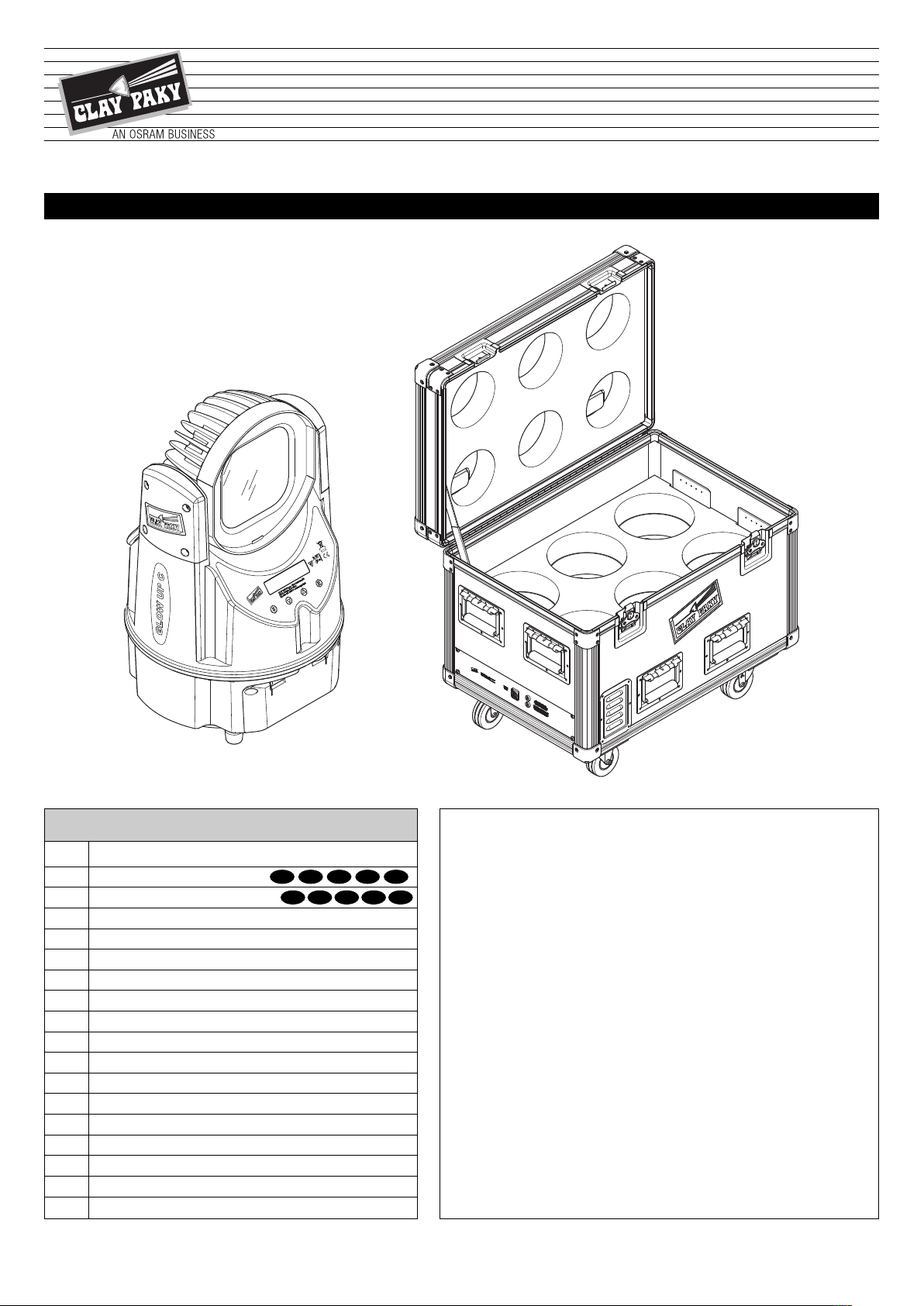
Packing content - Fig. 1
NPACKING AND PREPARATION
U
OPTIONAL ACCESSORY C71110
IST002/001
2
REMOVAL OF THE PROTECTIVE FILM
GLOW UP
12
Page 13

3
1
2
3
2
3
1
4
NSTALLATION AND START-UP
I
Projector installation - Fig. 3
The projector can be installed on the floor resting on specific rubber feet, on a truss, on the ceiling or wall.
WARNING: the safety chain must be installed except when the projector rests on the floor. (Code 105015/801 available upon request). This
must be secured to the projector support structure and then hooked to the fastening point at the centre of the base.
4
Connecting and disconnecting the power cord - Fig. 4
When connecting the power cord the user can choose whether to use the GlowUp in one of the following ways:
1) Power cord connected for battery charge.
2) Power cord connected for projector power (thus bypassing battery operations).
The GlowUp cannot work in both ways simultaneously.
When the projector is powered by connection to the mains, it could be necessary to adopt appropriate measures to avoid EMI disturbances to broadcast
receiver equipment.
GLOW UP
13
Page 14

ONTROL PANEL
L
N
D
MX
512
SIGNAL
S
CREEN
DMX 512
5 PIN
1
2
3
4
5
SIGNAL
C
5
Connections to the power mains - Fig. 5
Power Supply
6
Connections to the control signal line (DMX) - Fig. 6
Use a cable conforming to specifications EIA RS-485: 2-pole twisted, shielded, 120Ω characteristic impedance, 22-24 AWG, low capacity. Do not use
microphone cable or other cable with characteristics differing from those specified. End connections must be made using XLR type 3-pin male/female
connectors. A terminating plug must be inserted on the last projector with a resistance of 120 (minimum 1/4 W) between terminals 2 and 3.
IMPORTANT: The wires must not make contact with each other or with the metal casing of the connectors. The casing must be connected to the shield
braid and pin 1 of the connectors.
7
Switching on the projector - Fig. 7
The projector immediately turns on when the power cord is plugged in or, if used in battery mode, by pressing and holding down keys
several seconds.
Clay Paky GLOW UP Address xxx BAT xx%
The control panel (Figure 8) has a display and buttons for complete programming and management of the projector menu.
The display can be in one of two conditions: idle status and settings status.
When idle, the projector DMX address and percent battery charge are displayed.
If no button is pressed after a wait period (about 60 seconds) when in menu settings status, the display automatically returns to idle status. It should
be noted that when this condition occurs, any modified value that has not yet been confirmed with the
To turn off the GlowUP, hold down keys
Press
-Yes to turn off the GlowUP or press S-NO to return to the settings menu.
A
GLOW UP Software release x.x x xxxxx ??? *
and Sfor several seconds. A confirmation message will appear (Switch off?).
A
A
Display symbology
key will be cancelled.
and Sfor
A
* see page 15
GLOW UP
14
Page 15

When GlowUp is in idle status the information page will appear on the display:
DMX Address
Operating mode
see page 23)
(
Display symbology - (Link Status)
Transmission to DMX cable
Reception from DMX cable
Reception DMX from Radio (wireless)
Transmission DMX from Radio (wireless)
ADDR 001 BAT 40%
S
TND
Yy
Link status
(Wireless or Wired)
RES/W
F
Time or percent remaining
of the battery charge
Factory reset? Y/N
Warning Radio
W42 (radio board not found)
W43 (radio board not interact)
If errors W42/W43 appear on the display, do
an RDM Discovery (see page 16) to see if the
error disappears. If it does not, check the
intactness of the wireless board.
Initial projector address settings
An initial address must be set on each single project for the control signal.
Address settings: see page 16.
Button functions – Menu SET
SELECT
DOWN
UP
ENTER
• If pressed in idle status: Cyclically switches between idle status and menu settings.
• If pressed while setting a menu: Moves to an upper level without changing anything (exits the function)
Decreases the value displayed (with auto-repetitions), or passes to the next item on the menu
For quick access to the minimum parameter value, press the UP key while holding down the DOWN key.
Increases the value displayed (with auto-repetitions), or passes to the previous item on the menu
For quick access to the maximum parameter value, press the DOWN key while holding down the UP key.
Confirms the displayed value or activates the displayed function or opens the next menu.
GLOW UP
15
Page 16

BAT 40
%
??
SET MOD
UTTON FUNCTION
B
By pressing any button when Glow Up is in idle status, the BUTTON FUNCTION menu is accessed.
ymbol SET or II
S
M
Function Setting Play/Pause Stop Mode
Press SET SELECT Sto access the menus:
Program
MX Address
D
dvanced (Menu use is recommended for qualified technical personnel.)
A
Press ENTER
ode
M
MOD to select the Glow UP operating mode
A
Stand Alone
DMX
lave
S
Master
epeater
R
OD
NOTE: in a GlowUp series which is part of a battery, it is imperative to first select all the receivers and finally select the Transmitter.
II
PLAY/PAUSE UPBkey: activates or pauses a particular mode.
Play
Preset Colors
Sequences
Manual Control
Play Rec
STOPDOWN Ckey: deactivates the active programme.
GLOW UP
16
Page 17

PRESET COLORS FOR STAND ALONE “GLOWUP C”
Colour Reference
01 RGBW -0000
02 RED - 255 000
3 GREEN -0255 00
0
04 BLUE -00255 0
05 YELLOW - 255 255 00
06 CYAN -0250 185 0
07 MAGENTA - 255 0 140 0
08 WHITE -000100
09 ORANGE - 255 115 00
10 PINK - 127 00100
11 VIOLET - 255 0 184 200
2 AQUA - 85 255 105 0
1
13 SKY BLUE - 118 255 150 0
14 FULL WHITE - 255 255 255 255
15 COOL WHITE - 225 255 253 255
16 WARM WHITE - 255 255 220 255
17 WHITE 3200 - 255 176 0 255
18 WHITE 2500 - 255 99 0 255
19 YELLOW 2 LEE 101 133 145 00
20 STRAW LEE 103 255 255 0 240
21 ORANGE LEE 105 246 195 00
22 LIGHT ROSE LEE 107 218 00255
23 DARK PINK LEE 111 255 0 120 255
24 MAGENTA LEE 113 255 0 78 0
25 BLUE 2 LEE 115 0 255 175 0
26 MED BLUE GREEN LEE 116 0 255 160 0
27 DARK BLUE LEE 119 0 180 180 0
28 BRIGHT PINK LEE 128 255 0 141 95
29 MEDIUM BLUE LEE 132 0 255 200 0
30 GOLDEN AMBER LEE 134 255 175 0 25
31 DEEP GOLDEN AMBER LEE 135 255 140 0 25
32 PALE LAVENDER LEE 136 00100 190
33 APRICOT LEE 147 152 122 0 76
34 DARK LAVENDER LEE 180 0 114 144 112
35 CHOCOLATE LEE 156 238 189 0 227
36 JUST BLUE LEE 079 0 187 175 0
37 SURPRISE PINK LEE 194 78 00255
38 SCARLET LEE 024 255 0 58 113
39 SURPRISE PEACH LEE 017 145 00153
40 FIRE LEE 019 255 141 44 0
41 ENGLISH ROSE LEE 108 161 119 0 255
42 MAUVE LEE 126 255 0 208 150
43 BRIGHT BLUE LEE 141 0 255 186 37
44 ALICE BLUE ROSCO 378 0 255 223 140
45 ROSE INDIGO ROSCO 358 00255 133
46 URBAN BLUE ROSCO 081 0 255 187 35
47 COOL BLUE ROSCO 066 0 255 148 153
48 LIGHT SALMON ROSCO 030 255 112 0 162
49 MAYAN SUN ROSCO 318 150 114 0 162
50 CHERRY ROSE ROSCO 332 255 0 92 0
51 FLESH PINK ROSCO 034 255 0 132 255
52
SKELTON EXOTIC SANGRIA
ROSCO 039 255 0 180 100
RGBW
Bit value
GLOW UP
17
Page 18

Main Menu Level 1 Level 2 Level 3 Level 4
C
hoices /
V
alues
SET
Program
Edit Scene Scene 1-10
Preset Colors 0 - 255
R
ed
0
- 255
Green 0 - 255
Blue 0 - 255
White 0 - 255
Dimmer 0 - 255
Stop-Strobe 0 - 255
Edit Sequence Memory 1-10
Æ
A
dd step
Æ
Delete step
Æ
Modify step
DMX Recorder
Æ Æ
Memory x ?
Æ Æ
Memory erase ?
DMX Address
Æ Æ Æ
1-506
Advanced
Access Code 1234
Setup
Radio
Æ
Unlink Transmitter
Æ
Link Receivers
Æ
Unlink Receiver
Æ
TX Mode
Æ
RDM Discovery
Mode
Slave Priority
Cable
Wireless
Master Output
Cable + Wireless
Cable
Wireless
Repeater
Direction
Wireless to cable
Cable to wireless
Function
Repeat & Play
Repeat Only
Lock Option
Lock On / Off
Set Password XXXX
Power Mode
Æ
Mixed Mode
Æ
AC Mode
Æ
Battery Mode
Display
Æ
On / Off
Contrast
Æ
0-10
Charging answer Default answer Yes / No
Battery display
Æ
Automatic
Æ
Percentual
Æ
Time left
Fixture ID
Æ
xxxxxxx
Preset
Factory Reset OK ?
User Reset OK ?
User save OK ?
Transfer Set
Cable upload
Radio Upload
ENU SETTING
M
GLOW UP
18
Page 19

Main Menu Level 1 Level 2 Level 3 Level 4
Choices /
V
alues
SET
Advanced
Access Code 1234
Set Model
Æ Æ
Color
Æ Æ
Tunable White
Æ Æ
White
Æ Æ
Color LR
Æ Æ
Tunable White LR
Æ Æ
White LR
FW Uploader
Æ Æ
Appl. Upload
Æ Æ
Boot upload
Æ Æ
Transfer Set
Information
Charge Battery hour
Æ
hh:mm
Discharge Battery
hour
Æ
hh:mm
Battery Monitor
Æ
Voltage
Æ
Current
LED Temperature
Æ
Temperature
Æ
Max temperature
Total LED hours
Æ
hh:mm
System Version
Æ
Appl.release
Æ
Boot release
DMX Monitor
Æ
Channel 1-7
Reset
Reset to Slave W
Æ
OK ?
Reset to DMX W
Æ
OK ?
Factory Reset
Æ
OK ?
CPU Reset
Æ
OK ?
Test --- --- ---
GLOW UP
19
Continued
Continued
➔
➔
Page 20

Short-Cut Key -------------------------------------------
- Press ENTER and DOWN to switch off Glow UP (Switch off ? Yes/No).
- Press ENTER and UP to quickly open DMX address settings.
- Press ENTER and hold down for several seconds with GlowUP in idle conditions to restore ‘’Factory’’
settings. (Factory Reset).
‘’Factory Reset’’ is only applied to ‘’Current’’ Preset and not to ‘’User’’ Preset.
- Hold down the SELECT and UP keys or UP and DOWN keys to quickly open the Menus:
Factory Reset (’Factory Reset’’ is only applied to ‘’Current’’ Preset and not to ‘’User’’ Preset).
User Reset
User Save
Transfer Set
- Press the ENTER and DOWN keys to quickly open the Menus:
Unlink Transmitter
Link Receivers
Unlink Receiver
TX Mode
RDM Discovery
- Press ENTER twice to quickly set the function mode, selecting from the following options:
Stand Alone
DMX
Slave
Master
Repeater
Select Enter
UP
DOWN
SHORT-CUT KEYS MENU
GLOW UP
20
Page 21

SET – PROGRAM ……….
EDIT SCENE
To create/overwrite/modify a SCENE customised by the user:
1 to 10 scenes can be customised using each single GlowUP channel.
• Press ENTER to display Scene 1.
• Use the UP and DOWN keys to select from the ten available SCENES.
• Press ENTER to open the SCENE.
• A bit value can be associated with each GlowUp channel inside each SCENE using the UP and DOWN
keys.
• When finished with settings, press SELECT. A confirmation message appears: SAVE SCENE X ?.
• Press ENTER to confirm and save the SCENE or SELECT to return to the previous menu.
SET – PROGRAM ……….
EDIT SEQUENCE
It allows you to create a sequence made up of a series of SCENES saved by the user.
• Press ENTER to display MEMORY 1.
• Use the UP and DOWN keys to select from the ten available MEMORY.
• Press ENTER to open the MEMORY and add/delete/edit STEP with SCENE / SPEED / FADE as desired.
• Press ENTER to confirm the selection or SELECT to return to the previous Menu.
SET – PROGRAM ……….
DMX RECORDER
To record a scene sequence programmed on the unit. To accept a recording, the projector must be set to:
Slave --> Receiver.
Press ENTER, reset the "Memory" by pressing ENTER again. GlowUp is now ready to store control unit DMX
data (DMX waiting ...).
On completing the recording, press ENTER to save, otherwise press SELECT.
SET ……….
DMX ADDRESS
It allows the user to set the DMX address to be assigned to the projector.
Press Select twice with GlowUP in idle conditions to open the SET
m
enu
ET MENU
S
GLOW UP
21
Continued
Continued
➔
➔
Page 22

S
ET ……….
ADVANCED
To enable the "Menu Advanced" enter the code (1234) using the UP, DOWN and ENTER keys.
S
ET - ADVANCED – SETUP ……….
RADIO
It assigns the desired command to the GLOW UP 'Radio' module choosing from one of the following:
• Unlink Transmitter: Disconnected from the transmitter
• Link Receivers: Connected to all free receivers
• Unlink Receiver: Disconnected from all receivers
• Tx mode: It allows the user to select one of the two available transmission channels between G3
(recommended for those who do not use RDM-wireless commands) and G4 (only recommended if RDMwireless commands are used).
RDM discovery – to be used only when the wireless card is replaced; press ENTER to start the automatic
search option.
SET - ADVANCED – SETUP ……….
MODE
It allows the GlowUp operating mode to be assigned:
SLAVE PRIORITY: GlowUp operates as Slave, press ENTER to select the DMX signal reception priority in the
event of conflict between cable or wireless signal.
• Cable (default)
• Wireless
MASTER OUTPUT: GlowUp operates as Master, press ENTER and use the UP and DOWN keys to select
how the DMX signal is transmitted to other devices:
• Cable+Wireless
• Cable
• Wireless
REPEATER: GlowUp runs as a repeater.
In this case, select how GlowUP runs as a repeater meaning:
Direction: select whether the repeater should send the DMX signal from:
• Wireless to Cable
• Cable to Wireless
Function: select whether the repeater should run from:
• Repeat & Play (GlowUp repeats and plays)
• Repeat Only (GlowUp only runs as repeater)
To enable the REPEATER function, turn on (Enable) or off (Disable)
GLOW UP
22
Page 23

S
ET - ADVANCED – SETUP ……….
LOCK OPTION
I
t lets you assign a lock password, requested at each projector start up (Lock). The same password can be
used to access the ''Menu Advanced''.
Press ENTER and open the ‘’Lock’’ menu to enable ON or disable OFF the password request at start up.
• Select ON to enable. The previously entered password is displayed. Use the UP and DOWN and ENTER
keys to enter the desired numeric password.
• By selecting OFF, no password will be requested at projector start up.
Open the ‘’Set Password’’ menu and use the UP, DOWN and ENTER keys to assign the desired numeric
Password.
SET - ADVANCED – SETUP ……….
POWER MODE
Lets you select the set projector power type.
Press ENTER - current settings are displayed. Use the UP and DOWN keys to select from the 3 available
options:
• AC Mode: only runs with mains power, in the event of power outage, the G.U.S. 100 turns off.
• BATTERY Mode: directly battery powered when turned on without mains power; if mains power is on or
connected later, it automatically charges to 100% and then stops charging; if mains power is turned off, it
turns off (as with flight case).
• MIXED Mode (default): mixed operations, as per first firmware release. Press ENTER to confirm the
selection (the display blinks for several seconds) or SELECT to keep current settings and return to the
previous menu.
SET - ADVANCED – SETUP ……….
DISPLAY
Allows you to dim the display backlight 60 seconds after switching to idle status. To turn it back on, simply
press any key.
Enable OFF or disable ON for display backlight reduction.
SET - ADVANCED – SETUP ……….
CONTRAST
It lets the user adjust the display contrast, selecting display contrast values between 0 and 10.
SET - ADVANCED – SETUP ……….
CHARGING ANSWER
This allows a default answer to be assigned for the battery charging request, when the projector is powered by
the relative power cable (Powercon):
• On selecting YES, it will automatically switch to the powered by battery status 1 minute after the projector
strip cord is connected to the mains.
• On selecting NO, it will automatically switch to the powered by cable status (excluding the battery mode) 1
minute after the projector strip cord is connected to the mains.
GLOW UP
23
Continued
➔
Page 24

S
ET - ADVANCED – SETUP ……….
BATTERY DISPLAY
A
llows you to select how to display the battery charge in idle status.
• Press ENTER - current settings are displayed.
• Use the UP and DOWN keys to select from the 3 available options:
Automatic: displays the remaining battery charge in hours or as a percentage.
Percentual: displays the percentage of remaining battery charge.
Time left: displays the remaining time of the battery charge in hours.
• Press ENTER to confirm the selection (the display blinks for several seconds) or SELECT to keep current
settings and return to the previous menu.
SET - ADVANCED - SETUP ……….
FIXTURE ID
It allows you to display the GLOW UP ID address.
SET - ADVANCED – SETUP ……….
PRESET
It lets you set, save and transfer each GlowUp settings:
• Factory Reset: It assigns factory settings to the Glow UP
• User Reset: It assigns the settings previously saved by the user to GlowUp (see User Save)
• User Save: once all necessary GlowUp settings are set, it saves them in the memory to recall them in
the future.
• Transfer Set: It lets you transfer GlowUP settings to another either via cable (Cable Upload) or
Wireless (radio Upload).
SET – ADVANCED ……….
SET MODEL
Use to change/select the model to be assigned to the projector.
Use the UP and DOWN keys to select one of the following models:
• COLOR (GlowUP C with Wireless Solution radio board)
• TUNABLE WHITE(GlowUP TW with Wireless Solution radio board)
• WHITE(GlowUP W with Wireless Solution radio board)
• COLOR LR (GlowUP C with Lumen Radio radio board)
• TUNABLE WHITE LR (GlowUP TW with Lumen Radio radio board)
• WHITE LR (GlowUP W with Lumen Radio radio board)
SET – ADVANCED ……….
FW UPLOADER
It lets you transfer software (Appliance or Boot) and settings (Transfer Set) from one projector to all
connected projectors.
Press ENTER to select the above mentioned transfer mode either via Wireless (Radio upload) or cable
(Cable upload).
SET - ADVANCED – INFORMATION ……….
CHARGE BATTERY HOURS
This option allows the user to view the total number of battery load hours from construction to today.
GLOW UP
24
Page 25

S
ET - ADVANCED – INFORMATION ……….
DISCHARGE BATTERY HOURS
D
isplays total projector battery powered operating hours from construction to date.
S
ET - ADVANCED – INFORMATION ……….
BATTERY MONITOR
Allows you to display the battery voltage and current status.
SET - ADVANCED – INFORMATION ……….
LED TEMPERATURE
Displays the LED working temperature:
• Temperature (real-time LED temperature)
• Max Temperature (maximum temperature measured on LED)
To reset the “Max Temperature” value, simultaneously press the UP and DOWN keys and hold down for
several seconds. When (Rst?) appears, confirm by pressing ENTER.
SET - ADVANCED – INFORMATION ……….
TOTAL LED HOURS
This option allows the user to view the total number of LED operating hours from construction to date.
SET - ADVANCED – INFORMATION ……….
SYSTEM VERSION
Lets you view the 2 firmware versions loaded on the projector CPU board:
• Appliance release (Main firmware )
• Boot release (Backup software)
SET - ADVANCED - INFORMATION ……….
DMX MONITOR
Displays the DMX input level in bit for each projector channel.
SET - ADVANCED – RESET ……….
RESET TO SLAVE WIRELESS
Resets GlowUP and automatically sets SLAVE WIRELESS settings.
Default settings after Reset are the following:
· “Master Output”-> "Cable + Wireless"
· "Repeater"-> "Disable"
· "Repeater"-> "Function"->"Repeat & Play"
· "Repeater"-> "Direction"->"Wirel. to Cable"
· “DMX address” = 1
· "Display"-> Off
· “Contrast” = 5
· “MOD”-> "Master/Slave" -> ”Receiver”
· "Slave Priority"-> "Wireless
GLOW UP
25
Continued
➔
Page 26

S
ET - ADVANCED – RESET ……….
RESET TO DMX WIRELESS
R
esets GlowUP and automatically sets DMX WIRELESS settings.
Default settings after Reset are the following:
· “Master Output”-> "Cable + Wireless"
·
"Repeater"-> "Disable"
·
"Repeater"-> "Function"->"Repeat & Play"
· "Repeater"-> "Direction"->"Wirel. to Cable"
· “DMX address” = 1
· "Display"-> Off
· “Contrast” = 5
· “MOD”-> "Stand Alone/DMX"
SET - ADVANCED – RESET ……….
FACTORY RESET
Factory Reset is only applied to CURRENT Preset and not USER Preset
Resets GlowUP and automatically sets factory settings.
Default settings after Reset are the following:
· “Master Output”-> "Cable + Wireless"
· "Repeater"-> "Disable"
· "Repeater"-> "Function"->"Repeat & Play"
· "Repeater"-> "Direction"->"Cable to Wireless"
· ‘’DMX address’’ = 1
· "Display"-> Off
· “Contrast” = 5
· “MOD”-> "Stand Alone/DMX"
· "Slave Priority"-> "Cable"
SET - ADVANCED – RESET ……….
CPU RESET
Used to reset the CPU, no settings are reset.
SET - ADVANCED ……….
TEST
Used to test the correct operations of effects.
GLOW UP
26
Page 27

Operating Mode Descrizione Display
Stand Alone
Does not receive DMX and executes only
the Play
STND
DMX Receives DMX DMX
Slave
S
lave Glow UP receives (on address 1) if
the GlowUp Master is set in Play
s
equences.
Slave Glow UP receives on its DMX
address if GlowUp Master transmits a
recording DMX
SLV
Master Broadcasts sequences or recording DMX MAST
Repeater
Receives and repeat, depending on the
configuration set in the '' Advance Menu’’.
RPTR
OPERATING MODES
GLOW UP
27
Page 28

1
2
DM CONTROLS IMPLEMENTED FOR GLOWUP SERIES
R
Control PID GET SET Description controller side
DEVICE_INFO 0x0060 X
IDENTIFY_DEVICE 0x1000 X
DMX_START_ADDRESS 0x00F0 XX
SOFTWARE_VERSION_LABEL 0x00C0 X
SUPPORTED_PARAMETERS 0x0050 X
PARAMETER_DESCRIPTION 0x0051 X
DMX_PERSONALITY 0x00E0 XX
DMX_PERSONALITY_DESCRIPTION 0x00E1 X
MANUFACTURER_LABEL 0x0081 X
EVICE_LABEL 0x0082 XX
D
SENSOR_DEFINITION 0x0200 X
SENSOR_VALUE 0x0201 X
RECORD_SENSORS 0x0202 X
DEVICE_MODEL_DESCRIPTION 0x0080 X
Gathers information from the device
Makes the red leds on the addressed device pulse
Reads or sets the DMX address
Reads the firmware version
athers the PIDS on the non-basic controls
G
Gathers information on the controls related to the manufacturer
Reads or sets the channel mode
Reads the description of the channel mode
Reads the manufacturer name
Reads or writes a label on the device
Reads the description of the sensors present
Reads the level of the led temperature sensor
Saves the current temperature level
Reads the text description of the model
MANUAL ZOOM - ANTENNA
8
NO TES: To achieve
best wireless performance, it is recommended to position
GlowUp with the aerial
side facing the transmitter, when possible.
Antenna
Manual zoom - Fig. 8
The GlowUP has a manual zoom located on the back of the projector head.
GLOW UP
28
Page 29

4
3
1
2
1
2
Fuse 6,3x32mm
10AT 250Vac
(030470)
Fuse 6,3x32mm
3AT 250Vac
(030471)
9
AINTENANCE
M
Charging glow up - Fig. 9
From 1 to 6 Glow Ups can be simultaneously charged by appropriately connecting and powering the flight-case.
10
Replacing flight case fuses - Fig. 10
Each flight-case has 2 fuses associated with the main power cord connection and one fuse for each Glow UP charge station.
GLOW UP
29
Continued
➔
Page 30

3
4
6
5
2
1
11
Battery removal - Fig. 11
This product contains lithium iron tetraphosphate rechargeable battery. To protect the environment, please discard the battery at the end
of its working life according to current law.
LiFePO4
Notes on how to achieve correct battery operations
1) Do not tamper with the control electronic circuit, do not tamper with the battery, do not short-circuit the battery.
2) Do not reuse GlowUp after self-switch off as this indicates a low battery; recharge GlowUp before using it again.
3) Do not leave the battery completely flat for over 5 days.
4) When not in use, recharge the battery at least every 4 months.
GLOW UP
30
Page 31

1
1
2
2
Parts requiring frequent cleaning.
Periodic cleaning - Fig. 12
To ensure optimal operation and performance for a long time it is essential to periodically clean the parts subject to dust and grease deposits. The frequency with which the following operations are to be carried out depends on various factors such as wear and the work environment quality (air humidity, dust, salinity, etc.). To remove dirt from external parts, use a soft cloth dampened with any liquid glass cleaning detergent.
It is recommended that the projector undergoes an annual service by a qualified technician for special maintenance involving at least the following
operations:
• General cleaning of internal parts.
• General visual check of internal parts, cabling, mechanical parts, etc.
• Electrical, photometric and functional checks; eventual repairs.
OPTIONAL ACCESSORIES
13 14
MAGNETIC HOLDER
C7111---2- black
C7111---7- white
GLOW UP
PADLOCK
Not commercialized from Clay Paky
31
Page 32

365.5
(14.37")
226
(
8.90")
165
(6.49")
ECHNICAL DATA
T
Source
4 10 W MC-E Cree leds
Led pilot power
40W
Optics
Optic zoom, manually adjustable, magnetic support
for any additional diffusers
LED color temperature
5700K GlowUP C
6000K GlowUP W
6200K cool white GlowUp TW
2700K warm white GlowUp TW
4200K cool+warm white GlowUp TW
Head adjustment
/-105°
+
Cooling
High efficiency external die-cast aluminium
Control
• Wireless DMX multimode: Master, Slave and
Reapeter
• Antenna built in the case IP65
• Master: can transmit other slaves the synchronised DMX scenes saved on it, both as macros
and as DMX recorder.
• Repeater: Receives the signal from the master
and re-transmits it to other Slaves hidden from
the master
• XLR 5-pole DMX-in DMX-out standard sockets
• Remote wireless board settings with PC
• Default macros, user programmable macros.
• DMX recorder to save scene sequences.
User interface
• LCD display 2 lines with 16 characters each,
backlit LED, white on black
• 4 membrane buttons
Input Power
170 VA
Body
• Injection pressed ABS case (UV protected)
• Finish: Polished metallic – Painted White or
Black
• carrier handle
• 4 non-slip rubber feet
Fittings
2 fast-look holes for omega hook-up
Safety
safety chain hole and padlock hole
Weight
7.5 Kg (16.8 lbs)
Protection rating
IP65
Valves
Compensation valve IP65
Battery
• Duration 10 hours full-white, 20 hours color fade
• 4-hour fast charge from flight case, 8 hours in
slow charge with PowerCon
• More than 2,000 charge/deplete cycles
• No memory effect
• No acid leaks
Working position
Works in any position
CE Marking
Complies with the following European Directives
- 2006/95/EC (LVD)
- 2004/108/EC (EMC)
- 2011/65/EU (RoHS).
THE PROJECTOR WILL NOT SWITCH ON
THE PROJECTOR WILL NOT SWITCH ON
DEFECTIVE PROJECTION
REDUCED LUMINOSITY
POSSIBLE CAUSES
No power supply.
LED burnt out or defective.
Signal transmission cable faulty or disconnected.
Incorrect addressing.
Fault in the electronic circuits.
Optic fault.
Dust or grease deposits.
External power
full range 100-240V 50-60Hz, PowerCon connector, for both battery charge and normal operations
CAUSE AND SOLUTION OF PROBLEMS
TROUBLE
CHECKS AND REMEDIES
Check the power supply voltage or battery charge.
Replace LED.
Replace the cables.
Check addresses (see instructions).
Call an authorised technician.
Call an authorised technician.
Clean (see instructions).
GLOW UP
32
Page 33

HANNEL FUNCTIONS
C
GLOW UP C
CHANNEL CHANNEL MODE
1
2
3
4
5
6
7
GLOW UP TW
CHANNEL
1
2
RED
GREEN
BLUE
WHITE
IMMER
D
STOP / STROBE
MACRO COLOR
INDEPENDENT CONSTANT INTENSITY MAX INTENSITY
COOL WHITE 6200K
WARM WHITE 2700K
CHANNEL MODE (Colour temperature)
TUNABLE WHITE
DIMMER
TUNABLE WHITE
DIMMER
3
GLOW UP W
CHANNEL
1
2
STOP / STROBE
DIMMER
STOP / STROBE
STOP / STROBE
CHANNEL MODE
STOP / STROBE
GLOW UP
33
Continued
➔
Page 34

BIT EFFECT
255
MAX BRIGHTNESS
0
LED OFF
CHANNEL 1
RED
CHANNEL 2
GREEN
CHANNEL 3
BLUE
BIT EFFECT
255
MAX BRIGHTNESS
0
LED OFF
BIT EFFECT
255 MAX BRIGHTNESS
LED OFF0
BIT EFFECT
248
2
40
232
224
220
216
212
208
204
2
00
196
192
188
184
180
176
172
168
164
1
60
156
152
148
144
140
136
132
128
124
120
116
112
1
08
104
100
96
92
88
84
80
76
72
68
64
60
56
52
48
44
40
36
32
28
24
20
0
-
-
-
-
-
-
-
-
-
-
-
-
-
-
-
-
-
-
-
-
-
-
-
-
-
-
-
-
-
-
-
-
-
-
-
-
-
-
-
-
-
-
-
-
-
-
-
-
-
-
-
-
-
-
-
-
255
2
47
239
231
223
219
215
211
207
2
03
199
195
191
187
183
179
175
171
167
1
63
159
155
151
147
143
139
135
131
127
123
119
115
1
11
107
103
99
95
91
87
83
79
75
71
67
63
59
55
51
47
43
39
35
31
27
23
19
COLD TONE
WARM TONE
PASTEL TONE
SEQ1
SKELTON EXOTIC SANGRIA
FLESH PINK
CHERRY ROSE
MAYAN SUN
LIGHT SALMON
COOL BLUE
URBAN BLUE
ROSE INDIGO
ALICE BLUE
BRIGHT BLUE
MAUVE
ENGLISH ROSE
FIRE
S
URPRISE PEACH
SCARLET
SURPRISE PINK
JUST BLUE
CHOCOLATE
DARK LAVENDER
A
PRICOT
PALE LAVENDER
DEEP GOLDEN AMBER
GOLDEN AMBER
MEDIUM BLUE
BRIGHT PINK
DARK BLUE
MED BLUE GREEN
BLUE 2
MAGENTA 2
DARK PINK
LIGHT ROSE
O
RANGE 2
S
TRAW
YELLOW 2
WHITE 2500
WHITE 3200
WARM WHITE
COOL WHITE
FULL WHITE
SKY BLUE
AQUAMARINE
VIOLET
PINK
ORANGE
WHITE
MAGENTA
CYAN
YELLOW
B
LUE
GREEN
RED
N
ONE
GLOW UP C
• COLOUR MIXING - channel 1 - 2 - 3
• WHITE - channel 4
MACRO COLOR - channel 7
•
• DIMMER - channel 5
• STOP / STROBE - channel 6
GLOW UP
34
Page 35

GLOW UP TW
BIT EFFECT
255 WARM WHITE
COOL WHITE 0
BIT EFFECT
255 MAX BRIGHTNESS
LED OFF0
100
6
200K 4200K 2700K
0
50
C
OOL WARM
COOL WARM
100
0
50
100
6
200K 4200K 2700K
0
50
100
0
50
BIT EFFECT
255 MAX BRIGHTNESS
LED OFF0
BIT
EFFECT
2
55 MAX BRIGHTNESS
LED OFF0
INDEPENDENT MODE
INDEPENDENT
COOL WHITE 6200K
WARM WHITE 2700K
TOP / STROBE
S
COOL WHITE - channel 1
•
CONSTANT INTENSITY & MAX INTENSITY MODE
CONSTANT INTENSITY
TUNABLE WHITE
DIMMER
TOP / STROBE
S
CONSTANT INTENSITY MAX INTENSITY
TUNABLE WHITE - channel 1
•
MAX INTENSITY
TUNABLE WHITE
DIMMER
TOP / STROBE
S
• WARM WHITE - channel 2
• STOP / STROBE - channel 3
• DIMMER - channel 2
• STOP / STROBE - channel 3
GLOW UP
35
Continued
➔
Page 36

BIT EFFECT
255 MAX BRIGHTNESS
LED OFF0
GLOW UP W
• DIMMER - channel 1
STOP / STROBE - channel 2
•
CLAY PAKY S.p.A. - Via Pastrengo, 3/b - 24068 Seriate (BG) Italy - Tel. +39-035 -654311 - Fax +39-035-301876 - www.claypaky.it
IST002/001 – EN - Rev.B 04/15
 Loading...