

Page 1
5
Alimentazione
L
N
ATLAS
ENGLISH
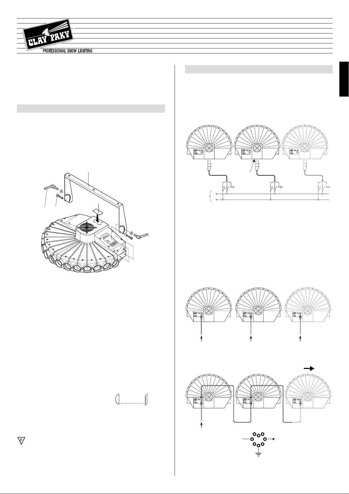
• Unpacking
Open the cardboard box, remove the projector from the packing and position it on a
horizontal support surface.Remove the components contained in the bags inside the
packing.
Identify the light bulb change label (1) on the appliance and, if necessary, replace it
with one of the optional multi-language labels.
Ensure that this label is never removed since it contains important safety information.
IMPORTANT: Carefully read all parts of the instruction manual. Knowledge of
the information and prescriptions contained in this document is essential for
correct, safe use of the appliance.
PROJECTOR INSTALLATION
1
5
POWER SUPPLY AND SET-UP
2
The projector is set up to operate at the power supply voltage and frequency shown
on the electrical data label (5) on the back of the projector itself. Ensure that these
values correspond to the electricity mains network voltage and frequency.
IMPORTANT: connection to a power supply system with efficient grounding is
mandatory (Class I appliance).
• Control signal connection
• Mains power connection
The operations described in this heading must be carried out by a licensed electrician.
The projector must be connected to the electricity mains network using the special socket provided.It is recommended that each projector is connected through
its own switch, so that it can be individually switched on and off remotely.
0 - 10V 0 - 10V 0 - 10V
0 - 10V
- Simultaneous and equal projector operation
- Independent projector operation
0-10V CONNECTION
The connection between projector and control unit and between several projectors
must be made with a shielded two-pole cable with Cannon 5 PIN XLR plug and socket at the ends.
Is
STOP
INSTRUCTION MANUAL
• Projector support preparation
Fix bracket (2) with the special screws (3) and lock it by tightening handles (4).
• Fitting the light bulb
Refer to the instructions for changing the light bulb in paragraph 5 MAINTENANCE.
• Projector installation
The projector can be fixed in any position, with its operating characteristics remaining unchanged.
IMPORTANT: Fix the projector in the required position using the special holes
in bracket (2).
The use of two 12 mm ø screws complete with nuts and spring washers is
recommended.
Ensure the stability of the fixing point before positioning the projector.
• Minimum distance of the lighted objects
The projector must be positioned so that the objects
struck by the light beam are at a distance of at least
0.5 m (1’ 8”) from the lens of the projector itself.
• Minimum prescribed distance of flammable materials from every point of the
body of the appliance: 0.07 m (3”).
Assembly of the appliance on normally flammable surfaces is permissible.
IMPORTANT: For better and more reliable operation of the appliance, the ambient temperature must not exceed 35° C (95° F). Protection level IP 20: the appliance is protected against penetration of solid bodies with a diameter of more than
12 mm (0.5”) (first figure 2), while it is not proof against drips, rain, sprays and jets
of water (second figure 0).
HMI 575
Mains
ENGLISH
4
3
1
2
®
(
1’ 8”
0.5 m
)
HMI 575
Page 2
6
CHANNEL FUNCTION
3
• STOP/STROBE - channel 1
With the cursor at 0% all bands are
obscured. In the cursor interval
between 0% and 25% the bands are
progressively opened from right to
left, creating a fan effect.From 25%
to 54.7% the bands are progressively obscured from right to left. From
54.7% to 95% a strobe effect is
obtained with an increasing frequency from 1 flash every four seconds
to 2 flashes/second.The aperture is
fixed from 95% to 100%.
CHANNEL
1 STOP/STROBE
FUNCTION
0
1
2
3
4
5
6
7
8
9
10
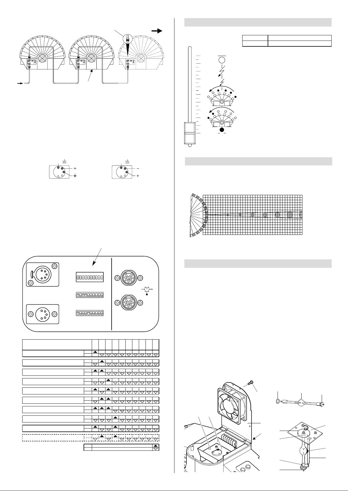
The connection between projector and control unit and between several projectors
must be made with a shielded two-pole cable with Cannon 5 PIN XLR plug and
socket at the ends.
For DMX connection the terminal pin (6) with a resistance of 100
Ω
between terminals 2 and 3 on the last projector. The terminal is not needed if an
RS232/423(PMX) signal is used.
It is essential that the wires do not come into contact with each other or with
the metal casing of the pin.
The casing of the plug/socket must be connected to the screen braid and to
foot 1 of the connectors.
After having performed all the operations described above, press switch (7) and
check that the light bulb switches on and that the automatic reset sequence starts.
• Projector coding (for digital signals)
Each ATLAS occupies one control channel. For this to be correctly addressed to each
projector, a coding operation must be perfor med for the projectors themselves.The
operation must be performed for each single ATLAS by setting the microswitches
according to the table below.
Setting the TEST switch to ON for a few seconds gives automatic reset with the projector switched on. Leaving the TEST switch ON gives the complete self-test; return
the switch to OFF at the end of the operation.
SIGNAL
SCREEN
SIGNAL
54
3
2
1
DMX
512
LENS
4
1
0
BEAM OPENING
m
0 5 10 15 20 25 30 35 40 DISTANCE m
0 0,1 0,14 0,18 0,22 0,26 0,30 0,34 0,38 DIAMETER m
1
HMI 575
6400 1600 710 400 256 177 130 100 lux
0” 16’ 5” DISTANCE ft in32’ 10” 49’ 3” 65’ 7” 82’ 98’ 5” 114’ 10” 131’ 3”
0” 4” DIAMETER ft in6”
7”
9” 10” 12” 1’ 1” 1’ 3”
595 149 66.0 37.2 23.8 16.4 12.1 9.29 fc
LIGHT BAND AND LIGHTING VALUE DIAGRAMS
Beam angle (0,5°)
MAINTENANCE
5
TEST
256
128643216842
1
ON
10987654321
DIGITAL INPUT
DIP
ANALOGUE INPUTS
STOP
Is
0-10V
Projector
4
- Channels
4
Projector
5
- Channels
5
Projector
6
- Channels
6
Projector
7
- Channels
7
Projector
8
- Channels
8
Projector
9
- Channels
9
Projector
10
- Channels
10
Projector
3
- Channels
3
Projector
2
- Channels
2
Projector
1
- Channels
1
ON
OFF
ON
OFF
ON
OFF
ON
OFF
ON
OFF
ON
OFF
ON
OFF
ON
OFF
124
8
163264
128
256
TEST
OFF
ON
OFF
ON
OFF
ON
CODE
IMPORTANT: the projector must be disconnected from the power supply before any
operation is started.
The maximum temperature of the appliance's outer surface in heat regime conditions
is 80° C (176° F). After switching off, do not remove any part of the appliance for 7
minutes, as shown in light bulb changing label (1).
After this time the probability of the bulb exploding is virtually nil.
If necessary, replace the bulb and wait a further 15 minutes to prevent burns. The
appliance is designed to retain splinters produced by a possible explosion of the b ulb .
It is mandatory to fit the lenses and moreover, if they show visible signs of damage
they must be replaced with original spare parts.
• Light bulb changing
Remove screws (8) and open fan hatch (9).
Unscrew knobs (10) of light bulb change plate (11) and remove it from the projector.
Slacken off ring-nut (12) of the light bulb to be replaced and remov e it from plate ( 13),
grasping it by its mount (14).Extract the new bulb from its pack, remove ring-nut (15)
and slacken of the other one (12).Screw the light bulb directly into bulb change plate
(13), grasping it by its mount (14). Position strip (16) in correspondence with mount
(17) and fully tighten ring-nut (12). Replace light bulb change plate (11) in the projec-
tor and tighten knobs (10). Close fan hatch (9) and fully tighten screws (8).
RS 232-423
DMX 512
RS 232/423(PMX) - DMX 512
7
6
18
15
12
8
9
1
11
10
13
14
17
12
16
11
18
Spotlight selection
SCREEN
RS232/423
(PMX)
1
2
45
SIGNAL
3
SIGNAL
Page 3

7
250V
10AT
5 x 20
FUSE
POSSIBLE REASONS
CHECKS & REMEDIES
TROUBLESHOOTING
6
No mains power supply. Check that power is reaching the
supply socket and/or that the fuses
are not blown.
THE PROJECTOR WILL NOT START UP
THE ELECTRONICS ARE INOPERABLE
DEFECTIVE PROJECTION
REDUCED LIGHTING
•
••
•
•
•
•
Light bulb blown or defective. Replace the bulb
(see instructions).
Signal transmission cable shortcircuited or disconnected.
Replace the cables.
Incorrect coding. Check the coding
(see instructions).
Fault in the electronic circuits.
Broken lenses.
Contact an authorised technician.
Contact an authorised technician.
TECHNICAL DATA
CONSTRUCTIONAL DETAILS
Devices
• Automatic power supply cut-off in
the case of overheating or a cooling
system breakdown.
• Automatic power supply cut-off
when the cover is opened.
Cooling
Forced ventilation cooling system
using axial fans.
Body
• Of diecast extruded aluminium
• Painted with epoxy powders
Stand
Made of steel painted with epoxy powders
Work position
It will operate in any position.
Weights and size
Weight: 27 kg (59 lbs 6 ozs)
ELECTRICAL
& MECHANICAL DETAILS
Power supplies available
• 220 - 240V 50Hz
• 200 - 220V 60Hz
• 200V 50Hz
• 200V 60Hz
• 260V 50Hz
The projector is designed to operate
at the mains frequency and voltage
given on the electrical data label on
the base of the appliance.
Light bulb
Metal iodides fed by a special incorporated power supply unit.
• Type HMI 575W
– Cap SFc 10-4
– Colour temperature 5600 K
– Light flux 49000 lm
– Average life 750 h
Power absorbed
1500 VA at 220V 50Hz
Motors
N. 1 step-by-step motor, operating in
microsteps and totally controlled by a
microprocessor.
COMMAND SYSTEMS
Channels
N. 1 control channel
Inputs
ATLAS is designed to analogue or
digital control signals transmitted
from control units or computers.
• Serial digital input
RS232/423(PMX) or DMX 512
• Analogue input 0 - 10V
7
ENGLISH
FAULTS
The products to which this manual refer comply with the
following European Union Directives:
• Low Voltage 73/23
• Electromagnetic Compatibility 89/836
WIRING DIAGRAM
With the desire to constantly improve the quality of its products, Clay Paky reser ves the
right to change the specifications mentioned in this document without prior notice.Thus
they should not be taken as binding.
8
• Fuse replacement
To replace the fuses, press tongue (19) and remove fuse box (20).
Replace the blown fuses with new ones of the type shown on label (21) located on
fuse box (20).
Return this by pushing it in until tongue (19) clicks.
• Periodic maintenance
Periodic cleaning of the parts subject to dust and grease deposits is indispensable
for keeping the projector's light yield unchanged.
Perfect operation can be ensured for a long time by following the directions given
below.
Use a soft cloth dampened with a liquid detergent for cleaning glass to remove dirt
from the lenses and filters.
IMPORTANT: do not use solvents or alcohol.
Parts that need frequent cleaning.
An annual general cleaning of the inside is also recommended, removing the dust
with a brush and sucking it out with a normal vacuum cleaner.
IMPORTANT: to ensure maximum uniformity of the light beams, the light bulb must
be located with protuberance (18), visible on the bulb, pointing towards the rear of
the projector.
CAUTION: The appliance is fitted with a high pressure light bulb with an
external starter.
- Carefully read the “User Instructions” provided by the light bulb's manufacturer.
- Replace the light bulb immediately if it is damaged or warped by heat.
1920
21
(24.8”)
630
(15.7”)
400
(28.5”)
725
 Loading...