

Page 1
3
ENGLISH
ASTRORAGGI TWIN
24V 150W
• Minimum distance from target objects
The projector must be positioned in such a way
that objects struck by the beam are located at
least 0.1 m (4”) from the lens.
• Minimum distance of inflammable materials from any part of the fixture:
0.02 m (1”).
The fixture may be mounted on surfaces rated normally inflammable.
IMPORTANT: For better and more reliable operation of the projector, the ambient
temperature must not exceed 35° C (95° F).
Protection factor IP 20: the appliance is protected against penetration of solid bodies more than 12mm (0.5”) in diameter (first digit 2), but can be damaged by spray,
jet, drip or rain water (second digit 0).
INST ALLING THE PROJECTOR
1
1
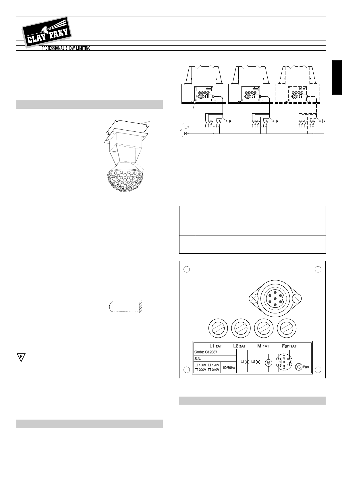
POWER SUPPLY AND SETUP
2
The projector is designed to operate at the voltage and frequency indicated on the
electrical data plate (2) located on the base.
Check that these two values correspond to the mains voltage and frequency.
IMPORTANT: the projector must be connected to a power supply circuit having
a proper earth system (Class I appliance).
• Electrical connections (supplied socket outlet)
• Connecting to the electrical power supply
The operations described in this heading must be carried out by a licensed electrician.
The projector must be wired up to the electrical power supply using the special socket connector provided. It is good policy to connect projectors to the power supply by
way of dedicated switches, so that each can be turned on and off individually from
a remote station.
MAINTENANCE
3
IMPORTANT: isolate the projector from the electrical power supply before commencing maintenance work of any description.
The maximum temperature on the outer surface of the projector under normal operating conditions is 80°C (176° F).
After switching off, do not remove any part of the projector for at least 2 minutes;
once this time has elapsed, the risk of a lamp exploding is practically zero.
If the lamp needs changing, wait a further 15 minutes to avoid the risk of burns.
In the event of a lamp exploding, the fixture is designed to prevent fragments of
glass from being scattered.
The lenses must be fitted at all times, and if visibly damaged must be replaced
promptly with genuine spares.
INSTRUCTION MANUAL
IMPORTANT: Read carefully. A thorough knowledge of the information and
prescriptions in this manual is essential for the correct and safe use of the
equipment.
• Unpacking
Open the box, remove the projector from the packing and place it on
a flat, horizontal surface.
Unpack the standard accessories
supplied with the fixture.
• Fitting the lamp
Refer to directions for replacement of the lamp given under heading 3 MAINTENANCE.
• Installing the projector
The projector can be mounted in any position without its operating characteristics
being affected.
Fix the drilled plate (1) to the supporting structure and then fix the plate to the projector using four M8 nuts and four lock washers.
Make sure that the anchorage is stable before positioning the projector.
2
Mains
ENGLISH
PIN CONNECTION
1-2 Fan:must be powered up constantly when projector is in use.
3-4 Motor: can be constantly on, constantly off or connected
through a manual switch or lighting controller.
3-5 Lamps: can be off / on or connected through a manual
3-6 switch or lighting controller.
®
(4”)
0.1 m
24V - 150W
Page 2
4
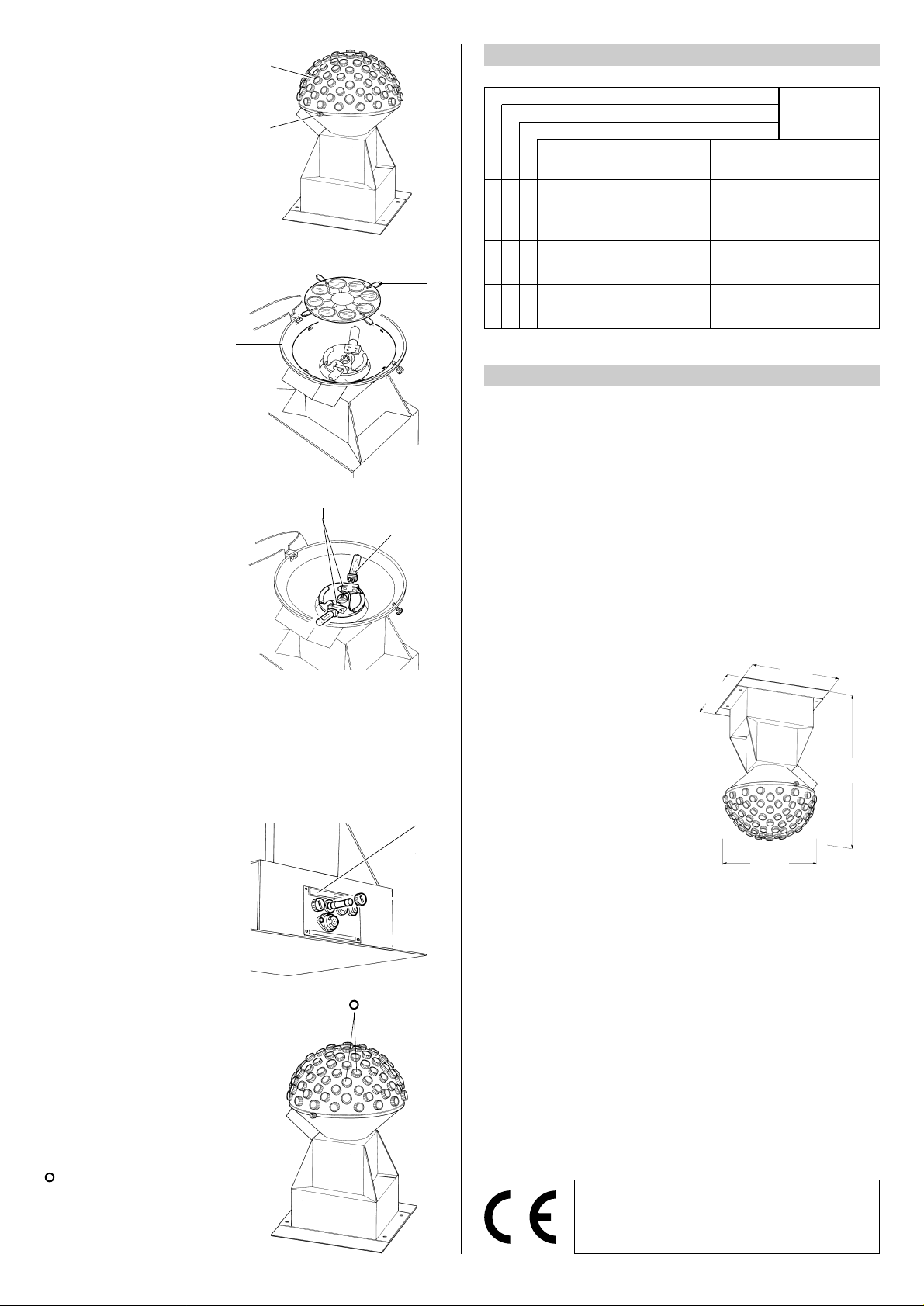
• Replacing the fuse
To replace the fuse unscrew fuseholder cap (11) and fit a new fuse of
the same type and rating as indicated on the label (12).
Refit the fuseholder cap and tighten
fully.
• Routine cleaning
To maintain the light output of the
projector undiminished, parts that
tend to accumulate dust and grease
must be cleaned periodically.
The projector will give long and trouble-free service if these simple
guidelines are followed.
To remove dirt from the lenses and
filters, use a soft cloth moistened
with any liquid detergent suitable for
cleaning glass.
IMPORTANT: do not use solvents or
alcohol
Parts that need cleaning frequently.
Internal parts should be cleaned once
a year by dislodging dust and dirt with
a brush and removing with a vacuum
cleaner.
CHECKS AND REMEDIESPOSSIBLE CAUSES
No electrical power supply.
Lamp expended or faulty.
Deposit of dust or grease. Change lamp (see instructions).
Change lamp (see instructions).
Check that power is available at the
mains, that the fuses are intact and
that the lighting controller (if present)
is functioning correctly.
FAULTS
9
10
• Opening the projector
Unscrew the knob (3) and open the
cover (4) to access the lampholder
assembly.
Once the necessary work has been
completed, close the cover (4) and
tighten the knob (3).
• Installing the colour wheel
(optional)
Remove the colour wheel (5)
from its packaging and fit it on
the projector ensuring that clips
(6) are aligned with locations (7)
in the protective cone (8) located
inside the projector.
• Changing the lamp
Remove the lamp (9) from fitting (10)
by gripping it at the base.Remove the
new lamp (9) from its box and insert
into the fitting (10), ensuring that the
pins are positioned correctly.
CAUTION:
- When fitting a new lamp, read the manufacturer’s instructions carefully.
- The lamp must always be changed without delay if damaged or def ormed by
heat.
TROUBLESHOOTING
4
PROJECTOR DOES NOT LIGHT UP
PROJECTION FAULTY
REDUCED BRIGHTNESS
•
•
•
••
TECHNICAL DATA
CONSTRUCTION
FEATURES
Cooling
Forced ventilation cooling system using
axial flow fans.
Housing
• Steel and extruded aluminium.
• Epoxy powder coated finish.
Operating position
Will function in any position.
Weight and dimensions
Weight: 19 kg (41 lbs 13 ozs)
ELECTRICAL / MECHANICAL
SPECIFICATIONS
Power supplies available
• 200-240V 50/60Hz
• 100-120V 50/60Hz
The projector is designed to operate at
the mains frequency and voltage given
on the electrical data label on the base
of the appliance.
Lamps
N. 2 halogen lamps supplied independently by means of built-in transformers:
• Type 24V 150W
- Cap GY 6.35
- Colour temperature 3300 K
- Luminous flux 6000 lm
- Average life 50 h
Power consumption
350VA a 230V 50Hz
Rotation speed of lamps
50 rpm
CONTROL SYSTEM
Simultaneous or sequential striking of
the lamps and motor rotation can be
delegated to an external controller.
5
7
6
5
8
4
3
(14.1”)
360
(17.7”)
450
(14.1”)
360
(13.8”)
ø 350
The products referred to in this manual comply with EC
Directives on:
• Low Voltage 73/23
• Electromagnetic Compatibility 89/336
The specifications published in this manual are not binding, and may be revised or updated at
any time by Clay Paky without notice in the interests of improving product quality.
11
12
 Loading...