

Page 1
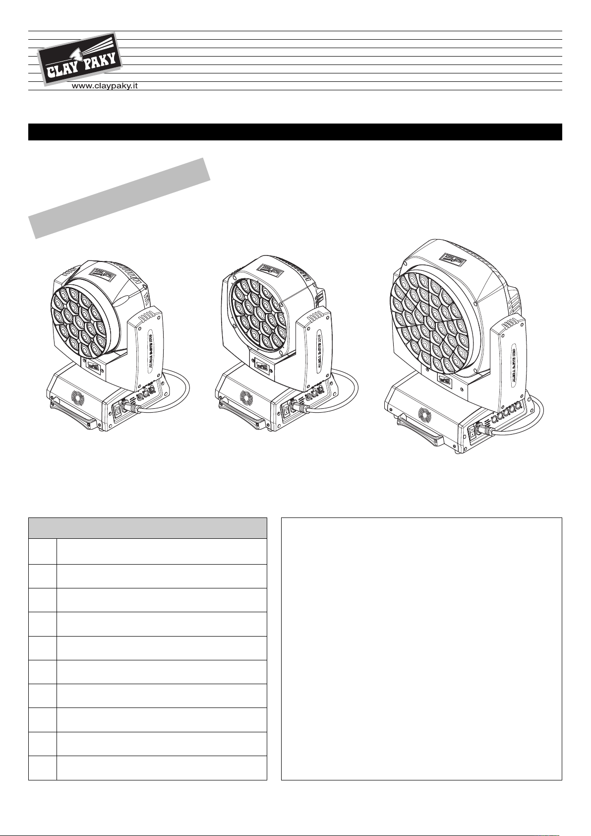
A.LEDA B-EYE K10 EASY
®
A.LEDA B-EYE K10
ENGLISH
A.LEDA B-EYE K20
C61415
C61419
61420
C
INSTRUCTION MANUAL
RY
A
ELIMIN
PR
Page
2
3
4
5
7
15
17
17
18
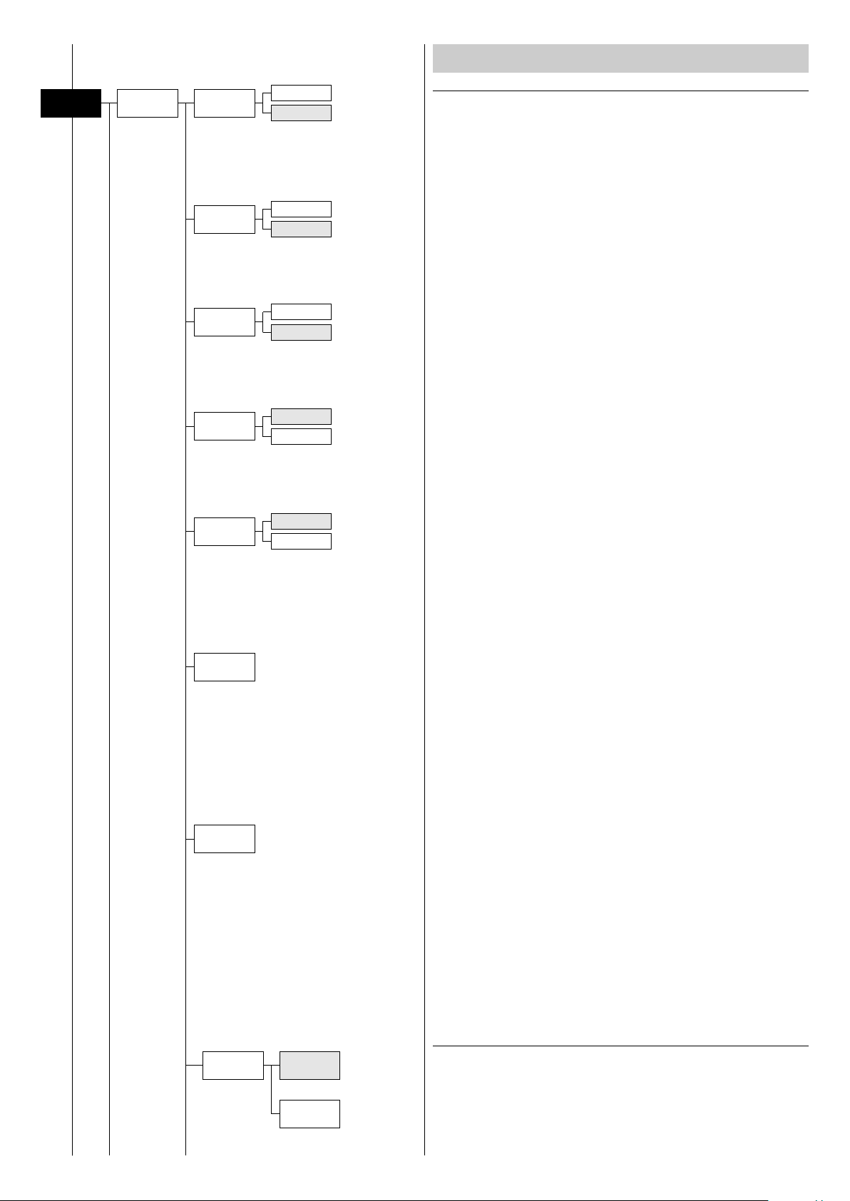
INDEX
Contents
Safety information
Unpacking and preparation
Installation and start-up
Control panel
Menu setting
Maintenance
Technical information
Cause and solution of problems
Channel functions
Congratulations on choosing a Clay Paky product!
We thank you for your custom.
Please note that this product, as all the others in the rich Clay
Paky range, has been designed and made with total quality to
ensure excellent performance and best meet your expectations
and requirements.
Carefully read this instruction manual in its entirety and keep it
safe for future reference. It is essential to know the information
and comply with the instructions given in this manual to ensure
the fitting is installed, used and serviced correctly and safely.
CLAY PAKY S.p.A. disclaims all liability for damage to the fitting
or to other property or persons deriving from installation, use and
maintenance that have not been carried out in conformity with this
instruction manual, which must always accompany the fitting.
CLAY PAKY S.p.A. reserves the right to modify the
characteristics stated in this instruction manual at any time and
without prior notice.
1
Page 2
LED
0.2
SAFETY INFORMATION
• Installation
Make sure all parts for fixing the projector are in a good state of repair.
ake sure the point of anchorage is stable before positioning the projector.
M
The safety chain must be properly hooked onto the fitting and secured to the framework, so that, if
the primary support system fails, the fitting falls as little as possible.
If the safety chain gets used, it needs to be replaced with a genuine spare.
• Minimum distance of illuminated objects
The projector needs to be positioned so that the objects hit by the beam of light are at least 0.20
metres (8”) from the lens of the projector.
Minimum distance from flammable materials
•
The projector must be positioned so that any flammable materials are at least 0.20 metres (8”) from
every point on the surface of the fitting.
• Mounting surfaces
It is permissible to mount the fitting on normally flammable surfaces.
• Maximum ambient temperature
Do not operate the fixture if the ambient temperature (Ta) exceeds 40° C (104° F).
IP20
tc90°C
• IP20 protection rating
The fitting is protected against penetration by solid bodies of over 12mm (0.47”) in diameter (first
digit 2), but not against dripping water, rain, splashes or jets of water (second digit 0).
• Protection against electrical shock
Connection must be made to a power supply system fitted with efficient earthing (Class I appliance
according to standard EN 60598-1).
It is, moreover, recommended to protect the supply lines of the projectors from indirect contact
and/or shorting to earth by using appropriately sized residual current devices.
• Connection to mains supply
Connection to the electricity mains must be carried out by a qualified electrical installer.
Check that the mains frequency and voltage correspond to those for which the projector is designed
as given on the electrical data label.
This label also gives the input power to which you need to refer to evaluate the maximum number
of fittings to connect to the electricity line, in order to avoid overloading.
• Temperature of the external surface
The maximum temperature that can be reached on the external surface of the fitting, in a thermally
steady state, is 90°C (194°F).
• Maintenance
Before starting any maintenance work or cleaning the projector, cut off power from the mains
supply.
• Light collimation system
This product contains internal light collimation system. Avoid intense light from any angle.
A.LEDA B-EYE
LiFePO4
Pb
Risk Group 2
According to
EN 62471
• Battery
This product contains a rechargeable lead-acid or lithium iron tetraphosphate battery. To preserve
the environment, please dispose the battery at the end of its life according to the regulation in force.
• Photobiological Safety
CAUTION. Possibly hazardous optical radiation emitted from this product. Do not stare at operating
lamp. May be harmful to the eyes.
The products to which this manual refers comply with the European Directives pursuant to:
• 2006/95/EC - Safety of electrical equipment supplied at low voltage (LVD)
• 2004/108/EC - Electromagnetic Compatibility (EMC)
• 2011/65/EU - Restriction of the use of certain hazardous substances (RoHS)
2
Page 3
1
9
0
°
9
0
°
9
0
°
9
0
°
LOCKED
UNLOCKED
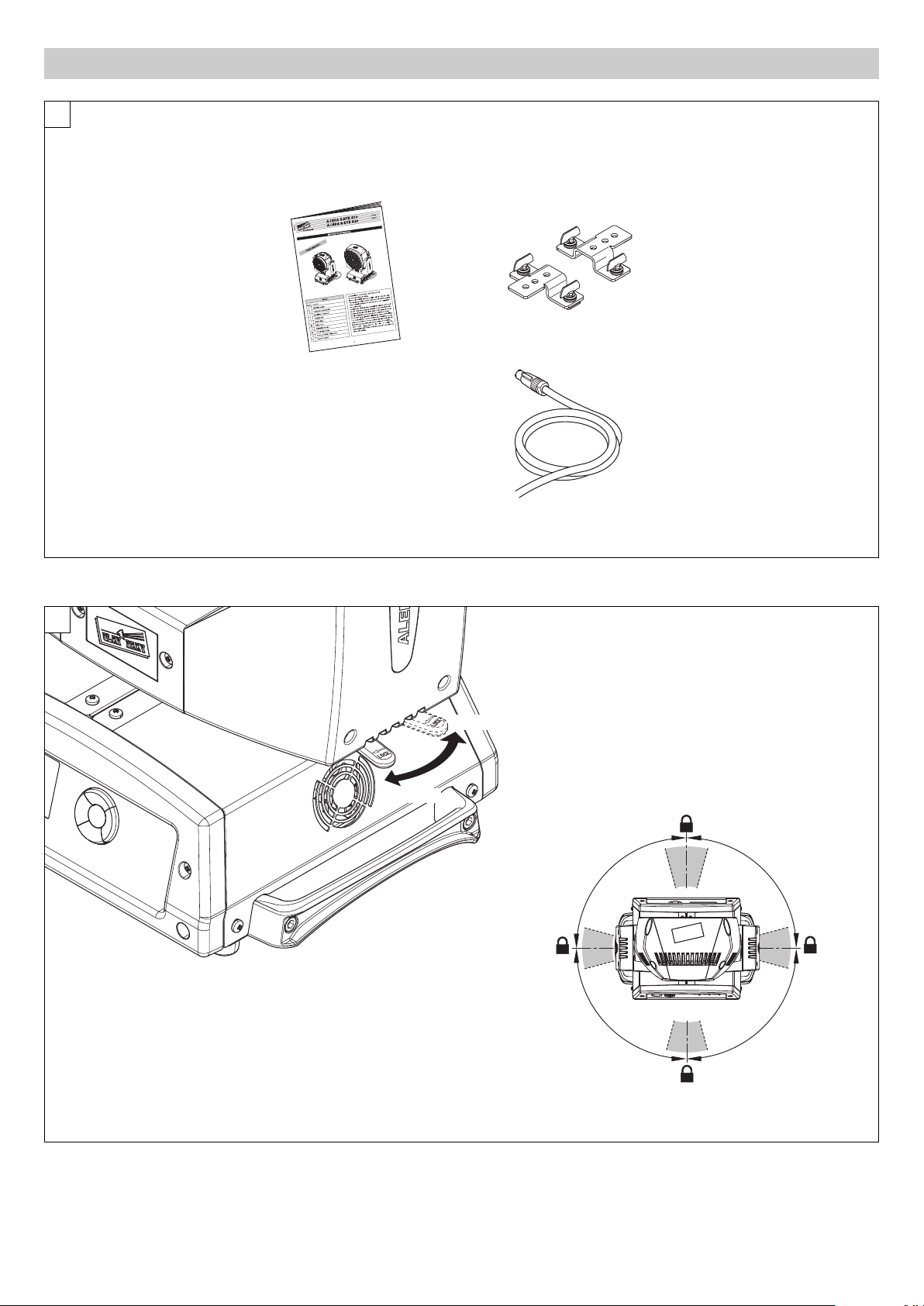
UNPACKING AND PREPARATION
IST009/001
2 x 183102/805
Packing contents - Fig. 1
2
PAN Mechanism Lock and Release (every 90°) - Fig. 2
A.LEDA B-EYE
3
Page 4
3
1
2
3
2
1
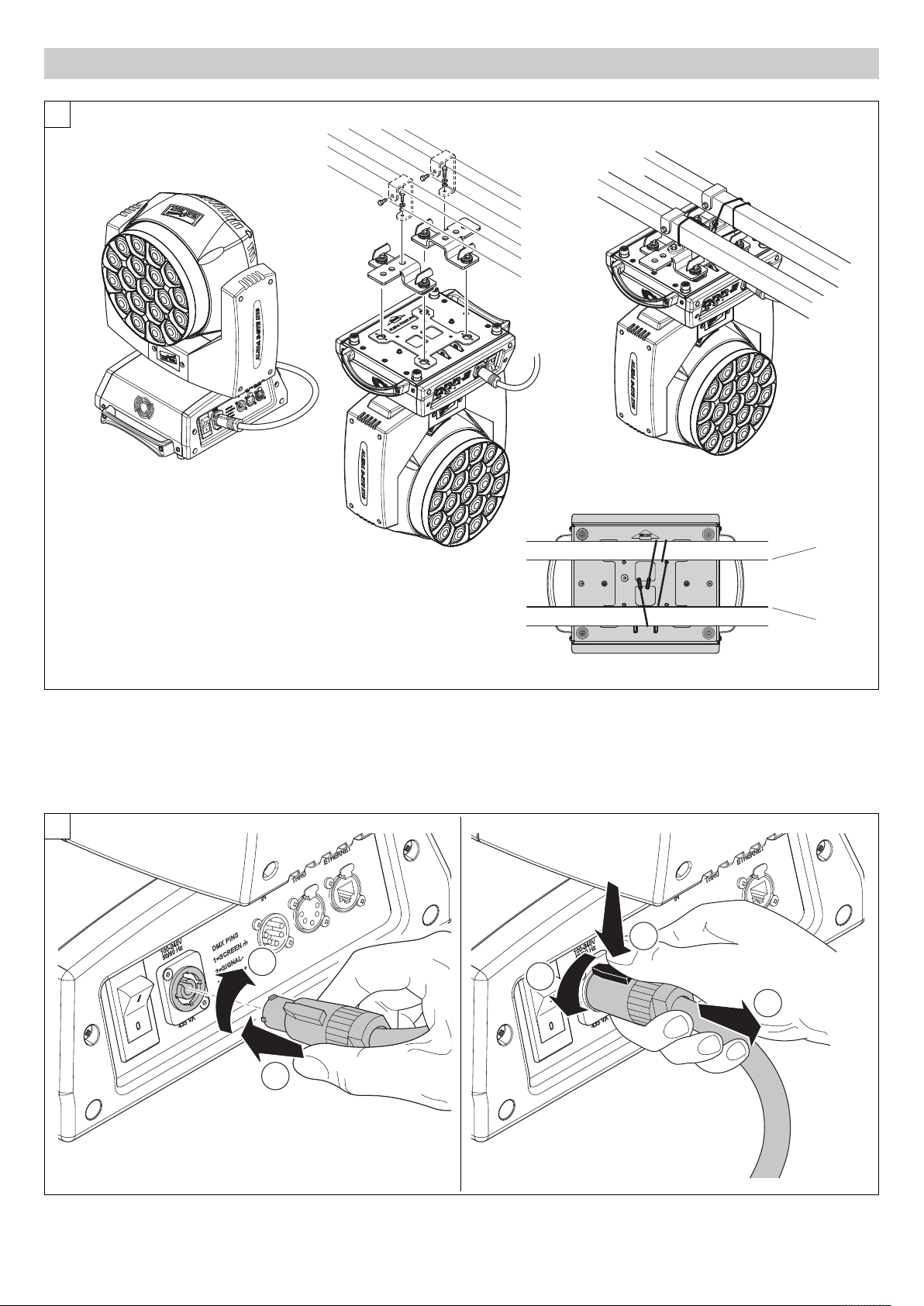
INSTALLATION AND START-UP
Installing the projector - Fig. 3
The projector can be installed on the floor resting on special rubber feet, on a truss or on the ceiling or wall.
WARNING: with the exception of when the projector is positioned on the floor, the safety cable must be fitted. (Cod. 105041/003 available on request).
This must be securely fixed to the support structure of the projector and then connected to the fixing point at the centre of the base.
4
Connecting and disconnecting power cable - Fig. 4
A.LEDA B-EYE
4
Page 5
CONTROL PANEL
7.5m
1
2
Dmx Address
Warning Message
Fixture ID
S
IGNAL
SCREEN
DMX 512
5 PIN
1
2
3
4
5
S
IGNAL
SCREEN
1
3
2
DMX 512
3 PIN
SIGNAL
SIGNAL
5
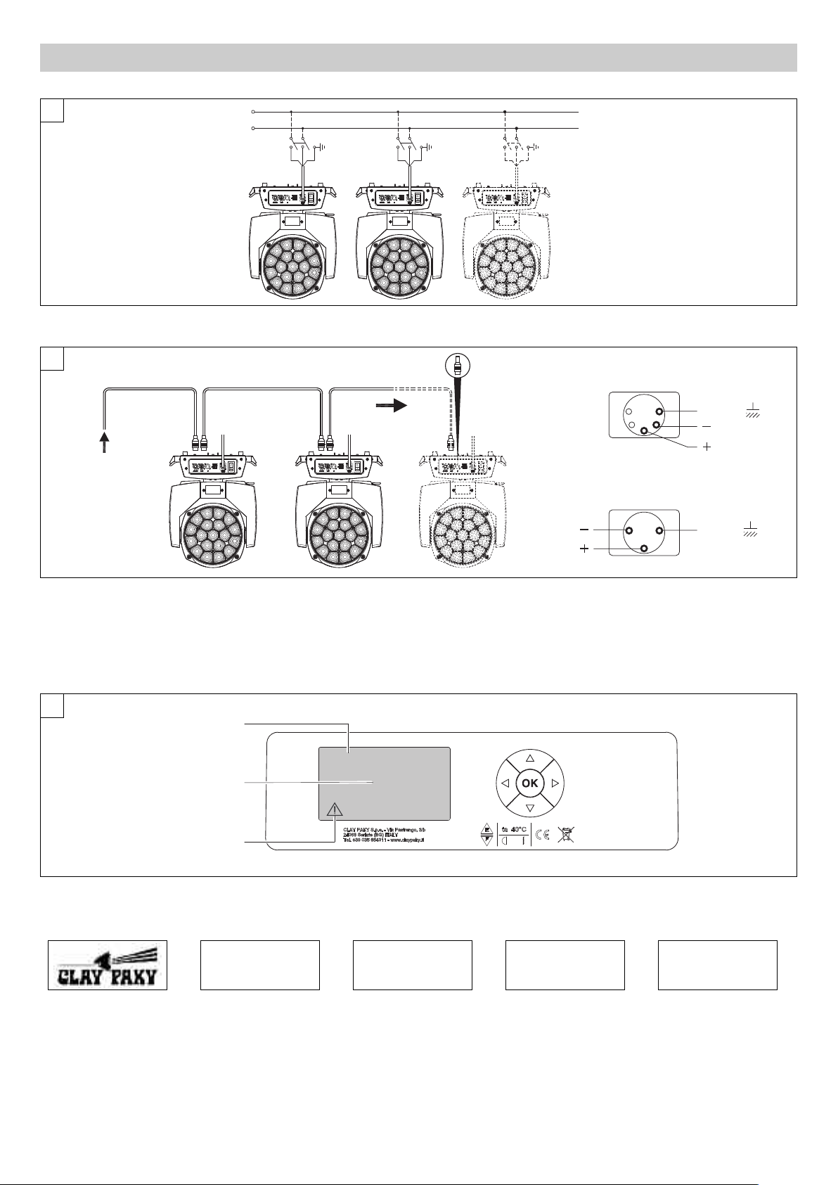
onnecting to the mains supply - Fig. 5
C
Mains
6
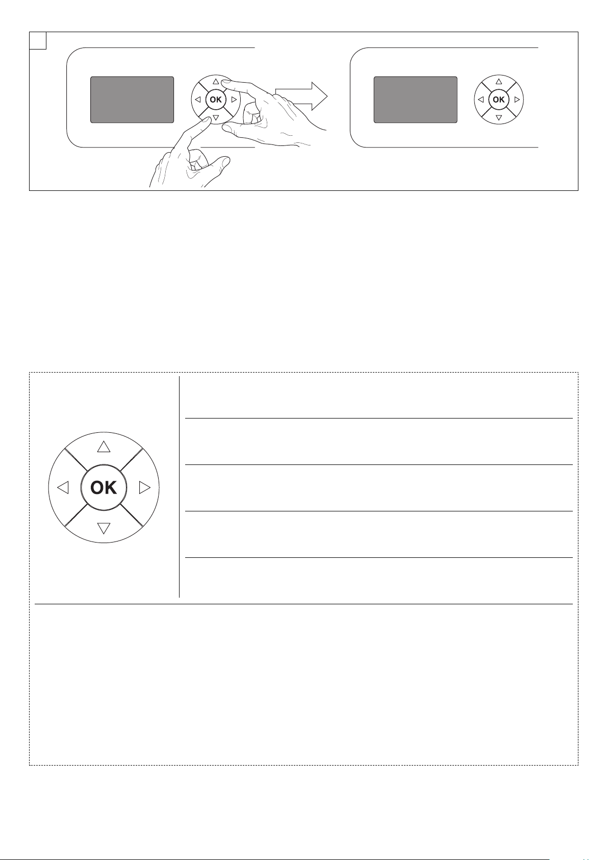
Connecting to the control signal line (DMX) - Fig. 6
Use a cable conforming to specifications EIA RS-485: 2-pole twisted, shielded, 120Ohm characteristic impedance, 22-24 AWG, low capacity. Do not use
microphone cable or other cable with characteristics differing from those specified. The end connections must be made using XLR type 3 or 5-pin male/female
connectors. A terminating plug must be inserted into the last projector with a resistance of 120Ohm (minimum 1/4 W) between terminals 2 and 3.
IMPORTANT: The wires must not make contact with each other or with the metal casing of the connectors. The casing itself must be connected to the
shield braid and to pin 1 of the connectors.
7
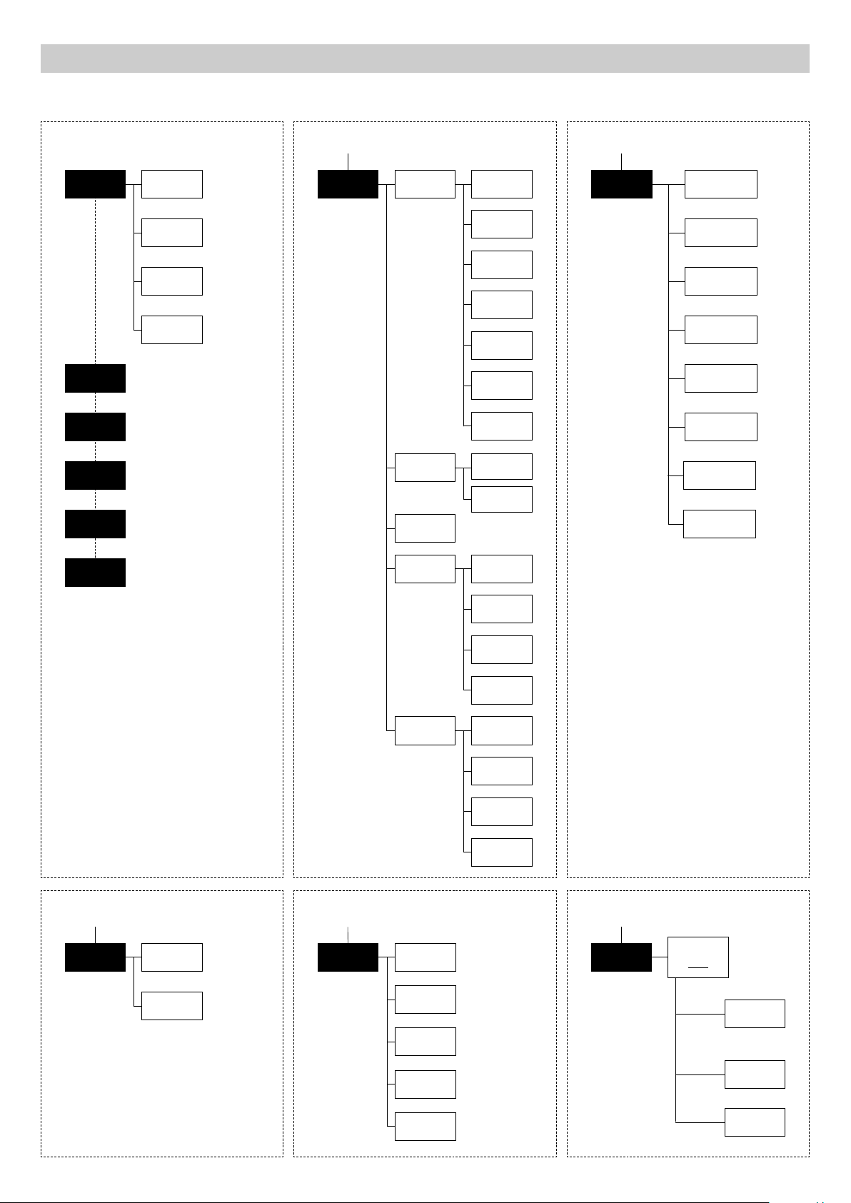
Switching on the projector - Fig. 7
Press the switch. The projector starts resetting the effects. At the same time, the following information scrolls on the display:
Model Firmware xxx (Fixture ID) System errors
A.leda B-EYE Version X.X.X Dmx Address xxx E: .........................
Date - Hour W: .........................
On conclusion of resetting in case of absence of the dmx signal, Pan and Tilt move to the “Home” position (Pan 50% - Tilt 50%). The control panel
(Fig. 7) has a display and buttons for the complete programming and management of the projector menu. The display can be in one of two conditions:
rest status and setting status. When it is in the rest status, the display shows the projector’s DMX address and the Fixture ID address (if set).
During menu setting status, after a wait time (about 30 seconds) without any key having been pressed, the display automatically returns to rest status.
It should be noted than when this condition occurs, any possible value that has been modified but not yet confirmed with the
key will be cancelled.
F
A.LEDA B-EYE
5
Continue
➔
Page 6
28
28
8
Reversal of the display - Fig. 8
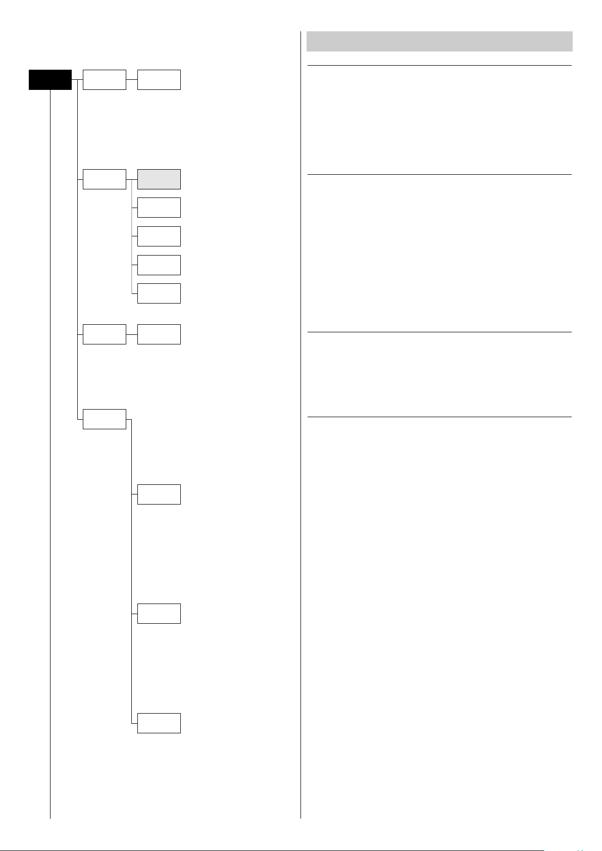
To activate this function, press UP
maintained even for the next time it will be switched on. To return to the initial state, repeat the operation all over again.
Setting the projector starting address
On each projector, the starting address must be set for the control signal (addresses from 1 to 512).
The address can also be set with the projector switched off.
Setting the address: see pag. 8.
Setting the projector Fixture ID
On each projector, the Fixture ID address must be set for an easy identification of the fixtures in an installation (ID from 1 to 255).
The Fixture ID address can be set with the projector switched off.
Setting the Fixture ID: see pag. 8.
and DOWNCkeys simultaneously while the display is in the rest mode. This status will be memorised and
B
Functions of the buttons - Using the menu
Confirms the displayed value, or activates the displayed function, or enters the successive
F
C
DOWN
B
UP
D
LEFT
E
RIGHT
USING THE MENU:
1) Press
2) Use the UP
• Setup (Setup Menu): To set the setting options.
• Option (Option Menu): To set the operating options
• Informations (Informations Menu): To read the counters, software version and other information.
• Manual Control (Manual control Menu): To trigger the test and manual control functions.
• Test (Test Menu): To check the proper functionning of effects
• Advanced (Advanced Menu): Access to the "Advanced menu" is recommended for a trained technical personnel.
To enable the "Advanced" see pag.13
3) Press
4) Use the UP
once – “Main Menu” appears on the display.
F
and DOWN Ckeys to select the menu to be used:
B
to display the first item in the selected menu.
F
and DOWN Ckeys to select the MENU items.
B
menu.
Decreases the value displayed (with auto-repetitions) or passes to the next item in the menu.
Increases the value displayed (with auto-repetitions) or passes to the previous item in a menu.
Return to the top level.
Commute from units, tens, hundreds, in the "Address", "Fixture ID" and "Calibration" menù.
Setting addresses and options with the projector disconnected
The projector’s DMX address, as well as other possible operating options, can also be set when the appliance is disconnected from the electricity supply.
All that is needed is to press
the display will switch off again after a wait time of 30 seconds.
A.LEDA B-EYE
to momentarily activate the display and thus access the settings. Once the required operations have been carried out,
F
6
Page 7
MENU SETTING
1
et Up
S
ption
O
Information
anual
M
Control
Test
mx
D
Address
hannel
C
ode
M
ixture ID
F
thernet
E
nterface
I
2
nvert
O
ption
an / Tilt
P
Silent
Mode
isplay
D
I
Pan
Invert
ilt
T
wap
S
Pan-Tilt
ncoder
E
an-Tilt
P
/T Homing
P
ode
m
an Home
P
ef Pos
D
ilt Home
T
ef Pos
D
tandard
S
uiet
Q
3
nformation
I
ystem
S
Errors
ixture
F
ours
H
LED
nergy Tot
E
System
Version
oard
B
Diagnost.
mx
D
onitor
M
Fans
onitor
M
Network
params
4
Advanced
Manual
Control
Reset
Special
Functions
Setting
5
Test
Pan / Tilt
Pan/Tilt
speed
Dimmer
curve
RGB
Gamma
Halogen
Mode
Default
Preset
User
Preset 1
User
Preset 2
User
Preset 3
6
Advanced
Access code
1234
A.LEDA B-EYE
Channel
Colour
Zoom
Rotation
All
7
Upload
Aleda fw
Setup
Model
Calibration
Continue
➔
Page 8
NOTE: On grey the default options
mx
et Up
S
D
Address
ddress xxx
A
SET UP MENU
DMX ADDRESS
NOTE: without the DMX signal the Address (XXX) flashing
Allows you to select the DMX ADDRESS.
1) Press
2) Use the UP
Address.
3) Press
- the current DMX Adress appear on the display.
F
and DOWN C, RIGHT Ekeys to plan the DMX
B
to confirm the selection or LEFT Dto keep current settings.
F
Channel
ode
M
ixture ID
F
Ethernet
Interface
Standard
hape
S
Extended
Extended
GBW
R
Full
Value xxx
CHANNEL MODE
Allows you to select a channel arrangement from the four available.
1) Press
2) Use the UP
settings:
- Standard
- Shape
- Extended
- Extended RGBW
- Full
3) Press
FIXTURE ID
Allows you to select the FIXTURE ID.
1) Press
2) Use the UP
3) Press
ETHERNET INTERFACE
It lets you set the Ethernet settings to be attributed to the projector.
1) Premere
2) Use the UP
options to set:
- the current settings appear on the display.
F
and DOWN Ckeys to select one of the following
B
to confirm the selection or LEFT Dto keep current settings.
F
- the current Fixture ID appear on the display.
F
, DOWN C, RIGHT Ekeys to plan the Fixture ID.
B
to confirm the selection or LEFT Dto keep current settings.
F
.
F
and DOWN Ckeys to select the “Ethernet Interface”
B
Control
Protocol
Repeat on
DMX
Universe
Control Protocol
It lets you select the “Control Protocol” Art-net to assign according to the
control unit used:
1) Press
2) Use the UP
- Disabled
- Art-net on IP 2
- Art-net on IP 10
3) Press
Repeat on DMX
It lets you enable the transmission of the Ethernet protocol by DMX signal
to all the connected projectors.
1) Press
2) Use the UP
- Disabled: DMX transmission disabled.
- Enabled on primary: DMX transmission enabled.
3) Press
Universe
It lets you assign the “Universe” number to be assigned to a series of
projectors.
1) Press
2) Use the UP
address.
3) Press
setting.
the current setting appears on the display.
F
and DOWN Ckeys to select one of the following settings:
B
to confirm the selection or LEFT Dto keep the current setting.
F
the current setting appears on the display.
F
and DOWN Ckeys to select one of the following settings:
B
to confirm the selection or LEFT Dto keep the current setting.
F
– the current Universe address appears on the display.
F
, DOWN C, RIGHT Ekeys to set the Universe
B
to confirm the selection or LEFT Dto keep the current
F
A.LEDA B-EYE
8
Page 9
Option
an / Tilt
P
nvert
I
Pan
Invert
ilt
T
Swap
an-Tilt
P
ncoder
E
Pan-Tilt
P/T Homing
Mode
Pan Home
Def Pos
Tilt Home
Def Pos
On
O
O
Off
O
Off
On
O
tandard
S
equenced
S
OPTIONS MENU
PAN / TILT
ff
n
n
ff
Invert pan
Used for reversing Pan movement.
1) Press
2) Use the UP
PAN inversion.
3) Press
Invert tilt
sed for reversing tilt movement.
U
1) Press
2) Use the UP
inversion.
3) Press
Swap Pan-Tilt
Used for swapping Pan and Tilt channels (as well as Pan fine and Tilt fine).
1) Press
2) Use the UP
Pan and Tilt channel swap.
3) Press
Encoder Pan-Tilt
Used for enabling the Pan / Tilt encoders.
1) Press
2) Use the UP
Pan / Tilt encoders.
3) Press
P/T Homing Mode
Lets you set the initial projector Reset mode.
1) Press
2) Use the UP
Standard: Pan & Tilt are simultaneously reset.
Sequenced: Tilt is reset first followed by Pan.
3) Press
Pan Home Def Pos
Lets you assign the Pan channel “home” position at the end of Reset,
without a DMX input signal.
1) Press
2) Use the UP
settings:
0 degree
90 degrees
180 degrees
270 degrees (default)
3) Press
Tilt Home Def Pos
Lets you assign the Tilt channel “home” position at the end of Reset,
without a DMX input signal.
1) Press
2) Use the UP
0%
12.5%
25%
50% (default)
75%
87.5%
100%
3) Press
- the current settings appear on the display (On or Off).
F
F
F
F
F
F
F
F
F
F
F
F
F
F
and DOWN Ckeys to enable (On) or disable (Off)
B
to confirm the selection or LEFT Dto keep current settings.
- the current settings appear on the display (On or Off).
and DOWN Ckeys to enable (On) or disable (Off) Tilt
B
to confirm the selection or LEFT Dto keep current settings.
- the current settings appear on the display (On or Off).
and DOWN Ckeys to enable (On) or disable (Off)
B
to confirm the selection or LEFT Dto keep current settings.
- the current settings appear on the display (On or Off).
and DOWN Ckeys to enable (On) or disable (Off)
B
to confirm the selection or LEFT Dto keep current settings.
, the current setting appears on the display.
and DOWN Ckeys to select one of the following settings:
B
to confirm the selection or LEFT Dto keep the current setting.
, the current setting appears on the display.
and DOWN Ckeys to select one of the following
B
to confirm the selection or LEFT Dto keep the current setting.
, the current setting appears on the display.
and DOWN Ckeys to select one of the following settings:
B
to confirm the selection or LEFT Dto keep the current setting.
A.LEDA B-EYE
Silent
mode
Standard
Quiet
SILENT MODE
It lets you select the “Silent Mode” from the two available.
1) Press
2) Use the UP
Standard: Maximum speed and consequently maximum effects noise level.
Quiet: reduces the speed of some effects (Pan/Tilt/Zoom/Zoom rotation),
thereby reducing their noise level.
3) Press Fto confirm the selection or LEFT Dto keep the current setting.
9
the current setting appears on the display.
F
and DOWN Ckeys to select one of the following settings:
B
Continue
➔
Page 10

O
ption
Display
O
Off
n
DISPLAY
Used for automatically reduce brightness on the display after about 30
seconds in idle.
1) Press
2) Use the UP
the decreasing of display brightness.
3) Press
- the current settings appear on the display (On or Off).
F
F
and DOWN Ckeys to enable (On) or disable (Off)
B
to confirm the selection or LEFT Dto keep current settings.
Special
unctions
F
Pan / Tilt
peed
s
Dimmer
Curve
RGB
Gamma
SPECIAL FUNCTIONS
Pan / Tilt speed
Lets you select two different Pan and Tilt speeds.
1) Press
2) Use the UP
- Normal
- Fast
3) Press
Dimmer Curve
Lets you select four different Dimmer channel curves.
) Press
1
2) Use the UP
settings:
- Curve 1
- Curve 2
- Curve 3
- Curve 4
3) Press
RGB Gamma
Lets you select three different RGBW gamma curves.
1) Press
2) Use the UP
- Gamma 1.0
- Gamma 1.5
- Gamma 2.0
3) Press
- the current setting appears on the display.
F
F
F
F
F
F
and DOWN Ckeys to select one of the following settings:
B
to confirm the selection or LEFT Dto keep current settings.
the current setting appears on the display.
and DOWN Ckeys to select one of the following
B
to confirm the selection or LEFT Dto keep current settings.
- the current setting appears on the display.
and DOWN Ckeys to select one of the following settings:
B
to confirm the selection or LEFT Dto keep current settings.
Setting
Halogen
Mode
Default
Preset
User
Preset 1
User
Preset 2
User
Preset 3
Reset To
Dafault
Go Back
Load
Preset 1
Save To
Preset 1
Load
Preset 2
Save To
Preset 2
Load
Preset 3
Save To
Preset 3
Halogen Mode
Lets you select five different halogen lamp simulations.
1) Press
2) Use the UP
settings:
- Halogen OFF
- Halogen Lamp 1 - 750 W
- Halogen Lamp 2 - 1000 W
- Halogen Lamp 3 - 1200 W
- Halogen Lamp 4 - 2000 W
- Halogen Lamp 5 - 2500 W
3) Press Fto confirm the selection or LEFT Dto keep current settings.
SETTING
Used to save 3 different settings of the items in the options menu and
relative submenus.
1) Press
2) Use the UP Band DOWN Ckeys to select one of the following
configurations:
- Default preset (*)
- User preset 1
- User preset 2
- User Preset 3
3) Press
4) Use the UP
- Load preset X to recall a previously stored configuration.
- Save to preset X to store the current configuration.
a confirmation message (Are you sure?) appears on the display.
5) Select YES to confirm the selection or NO to keep the current setting
and return to the next higher level.
(*) DEFAULT PRESET
By pressing the RIGHT
once entered in the "main menu" it is possible to quickly (short cut)
reset the default settings (DEFAULT PRESET).
Used for restoring default values on all options menu items and relevant
submenus.
- the current setting appears on the display.
F
F
F
and DOWN Ckeys to select one of the following
B
- “Default preset” appears on the display.
- “Load preset X” appears on the display.
and DOWN Ckeys to select:
B
key and the LEFT Dkey simultaneously
E
A.LEDA B-EYE
10
Page 11

1) Press F, a confirmation message (Are you sure?) appears on the display.
) Select YES to confirm the selction or NO to keep current setting.
2
OPTION DEFAULT
Invert Pan Off
Invert Tilt Off
Swap Pan-Tilt Off
Encoder Pan-Tilt On
P/T Homing Mode Standard
Pan Home Def Pos 270 degrees
Tilt Home Def Pos 50%
isplay On
D
Silent Mode Standard
P/T Speed Fast
Dimmer Curve Curve 1
RGB Gamma Gamma 1.5
Halogen Mode Halogen Off
INFORMATION MENU
nformation
I
A.LEDA B-EYE
ystem
S
rrors
E
Fixture
Hours
LED Energy
Tot
System
Version
Board
Diagnost.
Dmx
Monitor
Fans
Monitor
Network
params
Total XXX
Partial XXX
Reset...
Board Revis. Hw.rv.
CPU brd x.x.x x.x
com.dev x.x
0: PT-3f x.x x.x
1: Ld - Kxx x.x x.x
Board Status Err%
0:PT-3f Good 0.00
1: Ld - Kxx Good 0.00
Fan Speed (RPM)
PwrSp XXXX
Head XXXX
SYSTEM ERRORS
Shows a list of warnings and messages relevant to errors occurred since
the fixtures switching-on.
1) Pressing
you are allowed to reset the SYSTEM ERRORS list.
F
A confirmation message (Are you sure you want to clear error list ?)
appears on the display.
2) Select YES to reset the list or NO to go back.
FIXTURE HOURS
Used for displaying projector operating hours (total and partial).
1) Press
- Hours total and partial appears on the display.
F
Total counter
Counts the number of projector working life hours (from manufacture to date).
Partial counter
Counts the number of partial projector working life hours since the last
reset to date.
2) Press
to reset partial projector working hours a confirmation
F
message (Are you sure?) appears on the display.
3) Select YES to reset partial projectors counter or NO to keep the current
setting and return to the top menu level.
LED ENERGY TOT
Lets you view total LED working hours.
1) Press
- to display total and partial Watts/hour:
F
Total
Total LED working hours from construction to date.
Partial
LED working hours from last reset to date.
2) Press
to reset the partial counter. A confirmation appears on the
F
screen (Are you sure?)
3) Select YES to reset the partial counter or NO to keep the current setting
and open the next menu level.
SYSTEM VERSION
Used for displaying the software and hardware version of each board
installed in the projector.
CPU brd (CPU board)
0: PT-3f (Scheda Pan / Tilt)
1: Ld - Kxx (Scheda LED)
BOARD DIAGNOSTIC
Used for displaying the status error of each board installed in the projector:
0: PT-3f (Scheda Pan / Tilt)
1: Ld - Kxx (Scheda LED)
DMX MONITOR
Used for displaying the projector DMX channel level in bit (Val) and in
percentage (Perc).
FANS MONITOR
Used for displaying the speed of each fan installed in the projector:
PwrSp (fan PSU)
Head (fan head)
NETWORK PARAMS
Allows the "Network" parameters of the projector to be displayed or:
IP address: Internet Protocol address (two projectors must not have the
same IP address)
IP mask: 255.0.0.0
Mac address: Media Access Control: the projector’s Ethernet Address.
11
Continue
➔
Page 12

M
C
anual
ontrol
Reset
MANUAL CONTROL
o
N
es
Y
RESET
Used for resetting the projector.
1) Press Fto reset the projectors, a confirmation message (Are you
sure ?) appears on the display.
2) Select YES to starting reset the fixture or NO to keep the current setting
and return to the top menu level.
Test
Advanced
Channel
Pan-Tilt
olour
C
oom
Z
Rotation
All
Code
1234
CHANNEL
Used for setting channel levels from the projector control panel.
1) Press
2) Use the UP Band DOWN Ckeys to select the required channel:
3) Press Fand use the UP Band DOWN Ckeys to select the
required DMX level (value between 0 and 255).
4) Press LEFT Dto return to the top menu level.
- the first channel appears on the display.
F
TEST MENU
TEST
Allows you to check the proper functioning of effects.
1) Press
2) Use the UP
3) Press Fto confirm the selection or LEFT Dto keep current settings.
Test sequence:
Pan - Tilt effects (Pan & Tilt)
Colours
Zoom
Zoom rotation
All effects
to return to the top menu level.
F
and DOWN Ckeys to select the required test.
B
ADVANCED MENU
To enable the "Advanced Menu" set up the "Access code" (1234) using the
, DOWN C, RIGHT Ekeys.
UP
B
PressF- "Menu advanced" appears on the display
Upload
Aleda fw
Setup
Model
Calibration
Transfer the firmware on all
the connected fixtures ?
Are you sure ?
Yes/No
Changing to a wrong model
may damage the fixture.
Are you sure ?
Yes/No
UP LOAD FIRMWARE
Allows you to transfer the firmware from 1 fixture to all the connected fixtures.
1) Press
2) Select YES to start the firmware loading or NO to keep the current setting and return to the top menu level
SETUP MODEL
Allows you to change the default model of projector.
1) PressFa confirmation message appears on the display.
2) Select YES to define the model of projector or NO to keep the current
setting and return to the top menu level.
CALIBRATION
Allows you to adjust effects from the control panel to obtain perfect uniformity between the projectors.
1) Press
2) Using the UP
regulate.
3) Press
make the adjustment by setting a value between 0 and 255.
4) Press
tings and return to the top level.
FACTORY DEFAULT
Allows you to restore default values of all channels (128).
1) Press
calibration to factory default ?).
2) Select YES to reset calibration to factory default or NO to keep the
current setting and return to the top menu level.
, a confirmation message appears on the display.
F
- “channels” appears on the display.
F
F
F
F
and DOWN Ckeys, select the effect you wish to
B
and use the RIGHT E, UP Band DOWN Cbuttons to
to confirm the selection
– a confirmation message appears on the display (Reset
or
LEFT Dto keep current set-
A.LEDA B-EYE
12
Page 13

9
W
ARNING:
no alcohol
CAUTION:
• Light collimation system
This product contains internal light collimation system. Avoid intense light from any angle.
To avoid damage to the internal parts of the fixture when the fixture is not working, is recommended to turn the head down before turning the fixture off, so
that the front lenses of the fixture are invested as little as possible from the sun or any intense light.
• Set channel 20 (Zoom) to 255-bit before turning off the projector to facilitate the packaging of the projector.
• To ensure optimal operation and performance for a long time it is essential to periodically clean the parts subject to dust and grease deposits. The
frequency with which the following operations are to be carried out depends on various factors, such as the amount of the effects and the quality of
the working environment (air humidity, presence of dust, salinity, etc.).
It is recommended that the projector undergoes an annual service by a qualified technician for special maintenance involving at least the following
operations:
- General cleaning of internal parts.
- Restoring lubrication of all parts subject to friction, using lubricants specifically supplied by Clay Paky.
- General visual check of the internal components, cabling, mechanical parts, etc.
- Electrical, photometric and functional checks; eventual repairs.
Cleaning the lenses
Only use neutral soap and water to clean the lenses, then dry it carefully with a soft, non-abrasive cloth. (WARNING: the use of alcohol or any other
detergent could damage the lenses).
A.LEDA B-EYE
13
Continue
➔
Page 14

5
6
3
4
1
2
10
Battery removal - Fig. 10
LiFePO4
A.LEDA B-EYE
This product contains a rechargeable lead-acid or lithium iron tetraphosphate battery. To preserve the environment, please dispose the battery
at the end of its life according to the regulation in force.
Pb
14
Page 15

1
2
3
4
2
1
1
1
1
11
MAINTENANCE
Opening the covers - Fig. 11
12
Removing/Assembling the lens unit - Fig. 12
A.LEDA B-EYE
15
Continue
➔
Page 16

13
Replacing the line actuator - Fig. 13
THE PROJECTOR WILL NOT SWITCH ON
ELECTRONICS NON-OPERATIONAL
DEFECTIVE PROJECTION
REDUCED LUMINOSITY
POSSIBLE CAUSES CHECKS AND REMEDIES
No mains supply.
LED exhausted or defective.
Signal transmission cable faulty or disconnected.
Incorrect addressing.
Fault in the electronic circuits.
Lenses or reflector broken
Dust or grease deposited.
CAUSE AND SOLUTION OF PROBLEMS
PROBLEMS
Check the power supply voltage.
Call an authorised technician.
Replace the cables.
Check addresses (see instructions).
Call an authorised technician.
Call an authorised technician.
Clean (see instructions).
A.LEDA B-EYE
16
Page 17

479
(18.86")
358
(14.09")
253
(9.96")
4
23
(16.65")
248
(9.76")
360
(14.17")
290
(11.42")
Zoom IN
3
40
(
13.39")
Zoom OUT
180
(7.09")
Zoom IN
230
(9.06")
Zoom OUT
589
(23.19")
476
(18.74")
370
(14.57")
460
(18.11")
380
(14.96")
Zoom IN
430
(16.93")
Zoom OUT
200
(7.87")
Zoom IN
250
(9.84")
Zoom OUT
395
(15.55")
330
(12.99")
494
(
19.45")
358
(
14.09")
253
(
9.96")
423
(16.65")
248
(9.76")
360
(14.17")
350
(13.78")
Zoom OUT
310
(
12.20")
Zoom IN
233
(9.17")
Zoom OUT
1
89
(7.44")
Z
oom IN
A.Leda B-EYE K10
A.Leda B-EYE K10 easy
A.Leda B-EYE K20
TECHNICAL INFORMATION
Power supplies available
100-240V 50/60Hz
Input power
•
K20 - 750VA
•
K10 - 450VA
Total output
-EYE K10: t.b.d.
B
B-EYE K10 Easy: 4800 lumens
B-EYE K20: 9800 lumens
LED source
LED Osram Ostar RGBW - 15W
Average LED life: 50.000 h
Motors
5 (k10), 7 (k20) stepper motors, operating with microsteps,
totally microprocessor controlled.
Cooling
• High efficiency die-cast aluminium
Forced ventilation
•
Inputs
• DMX 512
• Ethernet
Working position
Functioning in any position.
Movable body
•
Movement by means of two stepper motors, controlled
by microprocessor.
•
Automatic repositioning of PAN and TILT after accidental
movement not controlled by control unit.
• Travel:
- PAN = 540°
- TILT = 210°
IP20 protection rating
• Protected against the entry of solid bodies larger than
12mm (0.47”).
• No protection against the entry of liquids.
CE Marking
Complies with the following European Directives
- 2006/95/EC (LVD)
- 2004/108/EC (EMC)
- 2011/65/EU (RoHS).
Weights
• K10: 14.5 kg
• K20: 21 kg
A.LEDA B-EYE
17
Page 18

A.LEDA B-EYE K10 EASY
CHANNEL FUNCTION
STANDARD
CHAN-
NEL
1
2
3
4
5
6
7
8
9
10
11
12
13
14
15
16
17
18
19
20
Red
Red fine
Green
Green fine
Blue
Blue fine
White
White fine
Linear CTO
Macro colour
Strobe
Dimmer
Dimmer Fine
Pan
Pan Fine
Tilt
Tilt Fine
Function
Reset
Zoom
CHANNEL MODE
SHAPES
CHAN-
CHANNEL MODE
NEL
1
Red
2
Red fine
3
Green
4
Green fine
5
Blue
6
Blue fine
7
White
8
White fine
9
Linear CTO
10
Macro colour
11
Strobe
12
Dimmer
13
Dimmer Fine
14
Pan
15
Pan Fine
16
Tilt
17
Tilt Fine
18
Function
19
Reset
20
Zoom
21
Shape Selection
22
Shape Speed
23
Shape Fade
24
Shape R
25
Shape G
26
Shape B
27
Shape W
28
Shape Dimmer
29
Background Dimmer
30
Shape Transition
31
Shape Offset
32
Foreground Strobe
33
Background Strobe
34
Background Select
EXTENDED
CHAN-
NEL
1
2
3
4
5
6
7
8
9
10
11
12
13
14
15
16
17
18
19
20
21
22
23
…
…
…
75
76
77
Red
Red fine
Green
Green fine
Blue
Blue fine
White
White fine
Linear CTO
Macro colour
Strobe
Dimmer
Dimmer Fine
Pan
Pan Fine
Tilt
Tilt Fine
Function
Reset
Zoom
Red LED 1
Green LED 1
Blue LED 1
Red LED …
Green LED …
Blue LED …
Red LED 19
Green LED 19
Blue LED 19
CHANNEL MODE
EXTENDED RGBW
CHAN-
NEL
1
2
3
4
5
6
7
8
9
10
11
12
13
14
15
16
17
18
19
20
21
22
23
24
…
…
…
…
93
94
95
96
Red
Red fine
Green
Green fine
Blue
Blue fine
White
White fine
Linear CTO
Macro colour
Strobe
Dimmer
Dimmer Fine
Pan
Pan Fine
Tilt
Tilt Fine
Function
Reset
Zoom
Red LED 1
Green LED 1
Blue LED 1
White LED 1
Red LED …
Green LED …
Blue LED …
White LED …
Red LED 19
Green LED 19
Blue LED 19
White LED 19
CHANNEL MODE
FULL
CHAN-
NEL
1
Red
2
Red fine
3
Green
4
Green fine
5
Blue
6
Blue fine
7
White
8
White fine
9
Linear CTO
10
Macro colour
11
Strobe
12
Dimmer
13
Dimmer Fine
14
Pan
15
Pan Fine
16
Tilt
17
Tilt Fine
18
Function
19
Reset
20
Zoom
21
Shape Selection
22
Shape Speed
23
Shape Fade
24
Shape R
25
Shape G
26
Shape B
27
Shape W
28
Shape Dimmer
29
Background Dimmer
30
Shape Transition
31
Shape Offset
32
Foreground Strobe
33
Background Strobe
34
Background Select
35
Red LED 1
36
Green LED 1
37
Blue LED 1
…
Red LED …
…
Green LED …
…
Blue LED …
89
Red LED 19
90
Green LED 19
91
Blue LED 19
CHANNEL MODE
A.LEDA B-EYE
18
Page 19

A.LEDA B-EYE K10
STANDARD
CHAN-
NEL
1
2
3
4
5
6
7
8
9
10
11
12
13
14
15
16
17
18
19
20
21
Red
Red fine
Green
Green fine
Blue
Blue fine
White
White fine
Linear CTO
Macro colour
Strobe
Dimmer
Dimmer Fine
Pan
Pan Fine
Tilt
Tilt Fine
Function
Reset
Zoom
Zoom Rotation
CHANNEL MODE
SHAPES
CHAN-
CHANNEL MODE
NEL
1
Red
2
Red fine
3
Green
4
Green fine
5
Blue
6
Blue fine
7
White
8
White fine
9
Linear CTO
10
Macro colour
11
Strobe
12
Dimmer
13
Dimmer Fine
14
Pan
15
Pan Fine
16
Tilt
17
Tilt Fine
18
Function
19
Reset
20
Zoom
21
Zoom Rotation
22
Shape Selection
23
Shape Speed
24
Shape Fade
25
Shape R
26
Shape G
27
Shape B
28
Shape W
29
Shape Dimmer
30
Background Dimmer
31
Shape Transition
32
Shape Offset
33
Foreground Strobe
34
Background Strobe
35
Background Select
EXTENDED
CHAN-
NEL
1
2
3
4
5
6
7
8
9
10
11
12
13
14
15
16
17
18
19
20
21
22
23
24
…
…
…
76
77
78
Red
Red fine
Green
Green fine
Blue
Blue fine
White
White fine
Linear CTO
Macro colour
Strobe
Dimmer
Dimmer Fine
Pan
Pan Fine
Tilt
Tilt Fine
Function
Reset
Zoom
Zoom Rotation
Red LED 1
Green LED 1
Blue LED 1
Red LED …
Green LED …
Blue LED …
Red LED 19
Green LED 19
Blue LED 19
CHANNEL MODE
EXTENDED RGBW
CHAN-
NEL
1
2
3
4
5
6
7
8
9
10
11
12
13
14
15
16
17
18
19
20
21
22
23
24
25
…
…
…
…
90
91
92
93
94
95
96
Red
Red fine
Green
Green fine
Blue
Blue fine
White
White fine
Linear CTO
Macro colour
Strobe
Dimmer
Dimmer Fine
Pan
Pan Fine
Tilt
Tilt Fine
Function
Reset
Zoom
Zoom Rotation
Red LED 1
Green LED 1
Blue LED 1
White LED 1
Red LED …
Green LED …
Blue LED …
White LED …
Red LED 18
Green LED 18
Blue LED 18
White LED 18
Red LED 19
Green LED 19
Blue LED 19
CHANNEL MODE
FULL
CHAN-
NEL
1
Red
2
Red fine
3
Green
4
Green fine
5
Blue
6
Blue fine
7
White
8
White fine
9
Linear CTO
10
Macro colour
11
Strobe
12
Dimmer
13
Dimmer Fine
14
Pan
15
Pan Fine
16
Tilt
17
Tilt Fine
18
Function
19
Reset
20
Zoom
21
Zoom Rotation
22
Shape Selection
23
Shape Speed
24
Shape Fade
25
Shape R
26
Shape G
27
Shape B
28
Shape W
29
Shape Dimmer
30
Background Dimmer
31
Shape Transition
32
Shape Offset
33
Foreground Strobe
34
Background Strobe
35
Background Select
36
Red LED 1
37
Green LED 1
38
Blue LED 1
…
Red LED …
…
Green LED …
…
Blue LED …
90
Red LED 19
91
Green LED 19
92
Blue LED 19
CHANNEL MODE
A.LEDA B-EYE
19
Continue
➔
Page 20

A.LEDA B-EYE K20
STANDARD
CHAN-
NEL
1
2
3
4
5
6
7
8
9
10
11
12
13
14
15
16
17
18
19
20
21
Red
Red fine
Green
Green fine
Blue
Blue fine
White
White fine
Linear CTO
Macro colour
Strobe
Dimmer
Dimmer Fine
Pan
Pan Fine
Tilt
Tilt Fine
Function
Reset
Zoom
Zoom Rotation
CHANNEL MODE
SHAPES
CHAN-
CHANNEL MODE
NEL
1
Red
2
Red fine
3
Green
4
Green fine
5
Blue
6
Blue fine
7
White
8
White fine
9
Linear CTO
10
Macro colour
11
Strobe
12
Dimmer
13
Dimmer Fine
14
Pan
15
Pan Fine
16
Tilt
17
Tilt Fine
18
Function
19
Reset
20
Zoom
21
Zoom Rotation
22
Shape Selection
23
Shape Speed
24
Shape Fade
25
Shape R
26
Shape G
27
Shape B
28
Shape W
29
Shape Dimmer
30
Background Dimmer
31
Shape Transition
32
Shape Offset
33
Foreground Strobe
34
Background Strobe
35
Background Select
EXTENDED
CHAN-
NEL
1
2
3
4
5
6
7
8
9
10
11
12
13
14
15
16
17
18
19
20
21
22
23
24
…
…
…
130
131
132
Red
Red fine
Green
Green fine
Blue
Blue fine
White
White fine
Linear CTO
Macro colour
Strobe
Dimmer
Dimmer Fine
Pan
Pan Fine
Tilt
Tilt Fine
Function
Reset
Zoom
Zoom Rotation
Red LED 1
Green LED 1
Blue LED 1
Red LED …
Green LED …
Blue LED …
Red LED 37
Green LED 37
Blue LED 37
CHANNEL MODE
EXTENDED RGBW
CHAN-
NEL
1
2
3
4
5
6
7
8
9
10
11
12
13
14
15
16
17
18
19
20
21
22
23
24
25
…
…
…
…
166
167
168
169
Red
Red fine
Green
Green fine
Blue
Blue fine
White
White fine
Linear CTO
Macro colour
Strobe
Dimmer
Dimmer Fine
Pan
Pan Fine
Tilt
Tilt Fine
Function
Reset
Zoom
Zoom Rotation
Red LED 1
Green LED 1
Blue LED 1
White LED 1
Red LED …
Green LED …
Blue LED …
White LED …
Red LED 37
Green LED 37
Blue LED 37
White LED 37
CHANNEL MODE
FULL
CHAN-
NEL
1
Red
2
Red fine
3
Green
4
Green fine
5
Blue
6
Blue fine
7
White
8
White fine
9
Linear CTO
10
Macro colour
11
Strobe
12
Dimmer
13
Dimmer Fine
14
Pan
15
Pan Fine
16
Tilt
17
Tilt Fine
18
Function
19
Reset
20
Zoom
21
Zoom Rotation
22
Shape Selection
23
Shape Speed
24
Shape Fade
25
Shape R
26
Shape G
27
Shape B
28
Shape W
29
Shape Dimmer
30
Background Dimmer
31
Shape Transition
32
Shape Offset
33
Foreground Strobe
34
Background Strobe
35
Background Select
36
Red LED 1
37
Green LED 1
38
Blue LED 1
…
Red LED …
…
Green LED …
…
Blue LED …
144
Red LED 37
145
Green LED 37
146
Blue LED 37
CHANNEL MODE
A.LEDA B-EYE
20
Page 21

B
IT
E
FFECT
2
55
0
L
ED ON
L
ED OFF
BIT
EFFECT
2550UP
LOW
OTE: On conclusion of resetting in case of absence of DMX signal, Pan & Tilt move to the "Home" position (Pan 128 bit - Tilt 128 bit ) all the others channels stay at 0 bit.
B
IT E
FFECT
255
…
224
…
188
…
144
…
117
…
99
…
54
…
10
0-9
2500 K
…
3200 K
…
4000 K
…
5000 K
…
5
600 K
…
6000 K
…
7000 K
…
8000 K
UNUSED RANGE
BIT COLOUR
LEE
R
EFERENCE
BIT VALUE
RG BW
2
09-255
208
207
1
91-206
1
84-190
1
80-183
179
175-178
174
1
72-173
168-171
162-167
1
57-161
151-156
149-150
147-148
1
46
1
45
142-144
138-141
136-137
1
34-135
1
31-133
129-130
128
127
126
125
123-124
121-122
120
119
118
117
115-116
114
113
112
110-111
100-109
89-99
78-88
68-77
62-67
49-61
46-48
45
35-44
32-34
31
30
29
27-28
23-26
20-22
19
18
17
16
15
14
13
12
11
10
0-9
-
-
1
97
181
1
74
170
1
69
165
1
64
162
1
58
152
147
141
139
137
136
135
132
1
28
1
26
1
24
1
21
1
19
118
117
116
115
113
111
110
109
108
107
105
104
103
102
100
90
79
68
58
52
39
36
35
25
22
21
20
19
17
13
10
-
-
-
-
-
-
-
-
-
-
-
2
55
2
55
1
28
77
1
81
255
2
55
82
2
55
255
2
22
253
255
0
77
219
255
255
0
2
55
2
27
8
4
2
06
0
74
206
206
51
255
255
217
255
255
255
255
255
230
237
245
41
0
0
243
243
255
255
255
255
255
255
255
255
198
152
156
0
255
255
216
255
255
0
0
0
255
-
2
35
2
55
2
55
0
2
55
168
1
99
214
4
6
181
8
4
171
143
255
255
197
197
58
255
5
3
4
1
2
55
2
55
1
86
255
255
255
255
20
109
130
138
148
141
122
166
160
163
202
219
194
255
117
117
107
87
112
83
65
100
135
56
114
115
126
0
137
201
237
0
255
255
0
255
0
-
6
6
1
22
1
43
255
9
5
64
4
9
90
2
28
0
26
13
87
0
79
61
0
143
3
6
5
6
1
3
0
2
55
82
56
56
51
15
33
28
31
23
31
0
0
0
0
0
0
130
135
133
39
0
0
0
2
0
0
0
0
9
9
0
0
0
25
61
255
0
255
255
0
0
-
2
55
2
55
0
0
0
0
0
0
0
0
0
0
0
0
0
0
0
0
0
0
0
0
0
0
0
0
0
0
0
0
0
0
0
0
0
0
69
0
0
0
0
0
199
197
130
107
141
0
0
0
0
0
0
0
0
0
193
255
255
0
0
0
0
0
0
-
W
hite
D
irty White
A
lice Blue
Congo Blue
D
ark Steel Blue
Deep lavender
L
ilac Tint
Daylight Blue
F
lame Red
Bastard Amber
D
eep Orange
Pale Gold
Apricot
Bright Blue
Primary Green
Special lavender
Pale Lavender
Deep Golden Amber
Medium Blue
B
right Pink
M
auve
D
ark Green
L
eaf Green
D
ark Blue
Light Blue
Steel Blue
Med Blu Green
Peacock Blue
Magenta
Dark Pink
Middle Rose
Light Salmon
English Rose
Light Rose
Orange
Deep Amber
Straw
Light Amber
Spring Yellow
Dark yellow green
Just Blue
Sky Blue
Lavender
Light Lavender
Pink Carnation
Medium Pink
Light Pink
Sunrise Red
Dark Amber
Gold Amber
Medium Amber
Fire
Surprise Peach
Straw Tint
Medium Yellow
Black
White 5000 K
White 3700 K
White 7000 K
Magenta
Yellow
Cyan
Blue
Green
Red
Macro color OFF
N
• RED
GREEN
BLUE
WHITE
RED FINE
•
GREEN FINE
BLUE FINE
WHITE FINE
• LINEAR CTO
Note: If CTO channel is active, the WHITE channel is disabled.
A.LEDA B-EYE
• MACRO COLOUR
21
Continue
➔
Page 22

BIT EFFECT
103 – 255
98 – 102
9
3 – 97
88 – 92
83 – 87
78 – 82
73 – 77
68 – 72
63 – 67
58 – 62
52 – 57
48 – 52
43 – 47
38 – 42
24 – 37
12 – 24
0 – 11
Reserved
Halogen Lamp Simulation, type 5 (2500 W) Linear CTO @ 0 bit
H
alogen Lamp Simulation, type 4 (2000 W) Linear CTO @ 0 bit
Halogen Lamp Simulation, type 3 (1200 W) Linear CTO @ 0 bit
Halogen Lamp Simulation, type 2 (1000 W) Linear CTO @ 0 bit
Halogen Lamp Simulation, type 1 (750W) Linear CTO @ 0 bit
Halogen Lamp Simulation OFF (Default)
RGBW Gamma curve 3 – gamma = 2.0
RGBW Gamma curve 2 – gamma = 1.5
RGBW Gamma curve 1 – gamma = 1.0
Dimmer Curve 4
Dimmer Curve 3
Dimmer Curve 2
Dimmer Curve 1
Pan Tilt Normal
Pan Tilt Fast (Default)
Function off – rearmed
DIMMER CURVE 1 - GAMMA 1 LINEAR
DIMMER CURVE 2 - GAMMA 1,5
DIMMER CURVE 3 - GAMMA 2,0
DIMMER CURVE 4 - S
BIT
2
55
0
B
IT
255
0
BIT
255
0
BIT
255
0
BIT
255
0
B
IT
255
0
BIT
2
55
0
B
IT
255
0
STOP STROBE - FOREGROUND STROBE - BACKGROUND STROBE
MACRO
BIT EFFECT
252 - 255
OPEN
0
- 3
CLOSED
213 - 225
RANDOM SLOW STROBE
4
SLOW STROBE (1 flash/sec)
1
03
FAST STROBE (25 flash/sec )
104 - 107
OPEN
1
08
SLOW PULSATION
(0,5 flash/sec)
2
08 - 212
O
PEN
226 - 238
RANDOM MEDIUM S TROBE
239 - 251
RANDOM FAST STROBE
207
FAST PULSATION
(25 flash/sec)
BIT EFFECT
2
55 FULL LIGHT
N
O LIGHT0
B
IT
E
FFECT
2
55
0
U
P
LOW
•
TILT
•
TILT FINE
•
DIMMER
•
• PAN • PAN FINE
DIMMER FINE
•
peration with option InvertPan
O
Tilt conventionally represented at 35 bit and option Invert Tilt
(
G
ff
O
G
Operation with option InvertPanGOn
(Tilt conventionally represented at 35 bit and option Invert TiltGOff)
• FUNCTION
ff)
O
Operation with option InvertPan
(Tilt conventionally represented at 35 bit and option Invert Tilt
Operation with option InvertPanGOn
(Tilt conventionally represented at 35 bit and option Invert Tilt
A.LEDA B-EYE
Off
G
The functions are actived passing through the “unused range” and staying 5 seconds
in necessary level.
Last selected function still active. Enable setting a new function.
Off)
G
Off)
G
22
Page 23

RESET
BIT
EFFECT
255
128
127
77
76
26
25
0
ZOOM RESET
U
NUSED RANGE
Pan / Tilt reset is activated passing throug the unused range
and staying 5 seconds in Pan / Tilt reset levels
Effects reset is activated passing throug the unused range
and staying 5 seconds in Effects reset levels.
COMPLETE RESET
COMPLETE RESET
PAN / TILT RESET
PAN / TILT RESET
Z
OOM RESET
Complete reset is activated passing throug the unused range
and staying 5 seconds in complete reset levels
0
1
27
STOP
2
55
FAS T ROTATION
1
93
SLOW ROTATION
191 - 192
STOP
190
SLOW ROTATION
BIT EFFECT
128
F
LINEAR ROTATION
AST ROTATION
BIT
MACRO EFFECT
193-255
191-192
128-190
127
126
….
3
2
1
0
CCW Rotation, speed from 3 RPH to 10 RPM
Stop rotation
CW Rotation, speed from 10 RPM to 3 RPH
Indexed zone. Lens angle = 60.00
Indexed zone. Lens angle = 59.52
Indexed zone. Lens angle = 1.42
Indexed zone. Lens angle = 0.94
Indexed zone. Lens angle = 0.47
Indexed zone. Lens angle = 0
BIT
MACRO EFFECT
128-255
127
126
125
…
1
0
Lens offset angle: 0.00 degree
Lens offset angle: +4.00 degree
Lens offset angle: +3.94 degree
Lens offset angle: +3.87 degree
Lens offset angle: +0.06 degree
Lens offset angle: 0.00 degree
BIT EFFECT
255
WIDE BEAM
0
NARROW BEAM
B
IT
E
FFECT
2550LED ON
L
ED OFF
•
• ZOOM
RED LED 1 to…
•
GREEN LED 1 to…
BLUE LED 1 to…
WHITE LED 1 to…
• ZOOM ROTATION
• ZOOM ROTATION (available on zoom channel from 0 bit to 42 bit)
• ZOOM ROTATION (available on zoom channel at 255 bit only)
A.LEDA B-EYE
23
Continue
➔
Page 24

Shape
Selection
Shape
Slot
Macro Name
On
K10
On
K20
Description
Random
colors
*1
EDAF EPAHSDEEPS EPAHS
BACKGROUND
SELECT (*3)(*4)
0-7 Macro OFF Yes Yes .a.N.a.N.a.N.a.N
81 Pixel 1 Yes Yes
92 Ring 1 Yes Yes
10 3 Ring 2 Yes Yes
11 4 Ring 3 No Yes
12 5 Pixel 1+Ring 1 Yes Yes
1
36Pixel 1+Ring 2 Yes Yes
14 7 Pixel 1+Ring 3 No Yes
15 8
Single ring
(Ramp -/+)
Yes Yes Yes
16 9
F
illed rings
(ramp -/+)
Yes Yes Yes
17 10 Open/Close 1 Yes Yes Yes
18 11 Open/Close 2 Yes Yes Yes
19 12 Random pixels 1 Yes Yes Yes
20 13 Random pixels 2 Yes Yes Yes
21 14
Rainbow 1
(Variable speed)
Yes Yes N.a.
0-63 = Angle 0-360°, static.
64-158 = max to min speed,
c.cw rotation
159-160 = STOP
161-255 = min to max speed,
cw rotation
0 = Snap effect
1-255 = Fade effect
For K10:
0-7 = wash
8-15 = Bkgnd rings
selection
16-255 = wash
For K20:
0-7 = wash
8-23 = Bkgnd rings
selection
22 15
Rainbow 2
(Fixed speed
withvariable
color offset)
Yes Yes N.a.
0-63 = STOP
64-158 = c.cw rotation
159-160 = STOP
161-255 = cw rotation
The value 64-158 or 161-255
change the rainbow angle offset
(the orange starting angle).
0 = Snap effect
1-255 = Fade effect
For K10:
0-7 = wash
8-15 = Bkgnd rings
selection
16-255 = wash
For K20:
0-7 = wash
8-23 = Bkgnd rings
selection
24-255 = wash
25 18 Half moon Yes Yes
26 19 Triangle Yes Yes
27 20 Segment 1 Yes Yes
28 21 Arc 1 Yes Yes
SHAPE OFFSET
N.a.
Static effects.
T
he ring or
rings used by
the macro are
turned-on with
the foreground
colour.
.a.N.a.N.a.N
0 = Snap effect
1-255 = Fade effect
For K10:
0-7 = wash
8-15 = Bkgnd rings
selection
16-255 = wash
For K20:
0-7 = wash
8-23 = Bkgnd rings
0-63 = Radius size, static.
64-158 = max to min speed,
Closing effect
159-160 = STOP
161-255 = min to max speed,
Opening effect
0-9 → continuous
10-255 → random
d
istribution of flash
from 2 to 20 fixtures
0 = Snap effect
1-255 = Fade effect
For K10:
0-7 = wash
8-15 = Bkgnd rings
selection
16-255 = wash
For K20:
0-7 = wash
8-23 = Bkgnd rings
selection
24-255 = wash
0-63 = Radius size, static.
64-158 = max to min speed,
Closing effect
159-160 = STOP
161-255 = min to max speed,
Opening effect
0-63 = STOP
6
4-158 = max to min speed,
Instant-on + fadeout.
159-160 = STOP.
161-255 = min to max speed,
FadeIn + FadeOut.
0-255 → select
random distribution
from 2 up to 20
fixtures
0 = Snap effect
1-255 = Fade effect
For K10:
0-7 = wash
8-15 = Bkgnd rings
selection
16-254 = wash
For K20:
0-7 = wash
8-23 = Bkgnd rings
selection
24-254 = wash
A
ll Fixtures:
255 = Mirror Effect
0-255 → select pixel
density
0-255 → angle
offset from 0 to 360°
N.a.
N.a.
0-63 = angle offset, 0-360°
64-158 = max to min speed,
c.cw rotation
159-160 = STOP
161-255 = min to max speed,
cw rotationt
0-255 → angle
offset from 0 to 360°
0 = Snap effect
1-255 = Fade effect
23 16 Fan Yes Yes
24 17 Bar 1
Yes Yes
For K10:
0-7 = wash
8-15 = Bkgnd rings
selection
16-255 = wash
For K20:
0-7 = wash
8-23 = Bkgnd rings
selection
24-255 = wash
For all fixtures:
- Macro 25, 26
255 = Mirror Effect with
bkgnd color
29 22 Arc 2 Yes Yes
- Macro 27, 28, 29
255 = Show Alternative
Color
HAPE SPEED - SHAPE OFFSET - SHAPE FADE - BACKGROUND SELECT
S
A.LEDA B-EYE
24
Page 25

Shape
Selection
Shape
Slot
Macro Name
On
K10
On
K20
Description
Random
colors
*1
EDAF EPAHSDEEPS EPAHS
BACKGROUND
SELECT (*3)(*4)
SHAPE OFFSET
4
134Vertical arc 1
42 35 Vertical arc 2 Yes Yes
43 36 Horizontal arc 1 No Yes
44 37 Horizontal arc 2 Yes Yes
45 38 Mirrored pixel Yes Yes
46 39 Pixel animation 1 Yes Yes
47 40 Pixel animation 2 Yes Yes
48 41 Pixel animation 3 Yes Yes
49 42 Pixel animation 4 Yes Yes
50 43 Pixel animation 5 Yes Yes
5
1 44
Semi arc (Ramp -
/+
)
Y
es Yes
52 45
Bumping arc
section
Yes Yes
53 46 Pixel animation 6 Yes Yes
54 47
Vertical ramp by
2
Yes Yes
55 48
Following pixel
b
y
2
Yes Yes
56 49 Syncopation Yes Yes
57 50 Bumping 1 Yes Yes
58 51 Bumping 2 Yes Yes
59 52 Bumping 3 Yes Yes
60 53
Vertical pixel
scrolling
Yes Yes
0 = Snap effect
1-255 = select the wake
of the faded macro
61 54
Random vertical
section
Yes Yes
62 55
Random central
section
Yes Yes Yes
63 56 Random ring 2 Yes Yes Yes
64 57 Random ring 3 No Yes Yes
65 58 Random ring 1+3 Yes(*2) Yes Yes
66 59 Random ring 2+3 Yes(*2) Yes Yes
67 60
Single pixel ring
1
Yes Yes
68 61
Single pixel ring
2
Yes Yes
69 62
Single pixel ring
3
No Yes
70 63 Spiral Yes Yes
0 = Snap effect
1-255 = select the wake
of the faded macro
.a.N.a.N46552-17
N.a.
0-255 → select
macro offset
0 = Snap effect
1-255 = Fade effect
0-255 → select
shape width
0 = Snap effect
1-255 = select the wake
of the faded macro
N.a.
0-255 → select the
number of rotating
led in the ring.
Available options: 1,
2, 3, 6, 9
The number of led
depends on the ring
size.
0 = Snap effect
1-255 = select the wake
of the faded macro
0-255 → select
macro width
0-255 → select
macro offset
0 = Snap effect
1-255 = Fade effect
0-255 → select
shape width
0 = Snap effect
1-255 = select the wake
of the faded macro
0-255 → select
macro offset
0 = Snap effect
1-255 = Fade effect
.a.N.a.N
0-63 = STOP, indexed speed
64-158 = max to min speed,
c.cw rotation.
159-160 = STOP.
161-255 = min to max speed cc
rotation.
For K10:
0-7 = wash
8-15 = Bkgnd rings
selection
16-254 = wash
255 = Mirror effect with
bkgnd color
For K20:
0-7 = wash
8-23 = Bkgnd rings
selection
24-254 = wash
255 = Mirror effect with
bkgnd color
Note:
Mirror effect
unavailable for macro
31.
Macro 67, 68, 69: the
mirror effect is available
only for options 1, 3, 9
0-255 → select
macro width
0-255 → select
random distribution
0 = Snap effect
1-255 = Fade effect
N
o Yes
3
0 23
Bar 2 (Variable
s
ize
)
Y
es Yes N.a.
0 = Snap effect
1
-255 = Fade effect
31 24
Random
ex
p
losion
Y
es Yes Yes
32 25 Segment 2 Yes Yes
33 26 x Bump No Yes
34 27 Image No Yes
0 = Sna
p
effect
3
528Bumping section Yes Yes
36 29 Ramp by 6 Yes Yes
3
730Ramp by 4 Yes Yes
38 31
Left/Right
scrollin
g
bar
Yes Yes
3
9 32
U
p/Down
scrollin
g
bar
Y
es Yes
40 33 Bar 3 Yes Yes
0-255 → select
shape width
0-255 → select
macro offset
0
-255 → select
shape width
0 = Snap effect
1
-255 = select the wake
of the faded macro
0-255 → select
s
hape width
0-255 → select
random distribution
0 = Snap effect
1
-255 = select the wake
of the faded macro
A.LEDA B-EYE
25
Page 26

SHAPE FADE
BIT
EFFECT
246-255
245
2
43
244
18
17
1
6
0-15
Smooth, fading curve with automatic gamma *
Smooth, fading curve gamma 2
Smooth, fading curve gamma 1,986
Smooth, fading curve gamma 1,993
Smooth, fading curve gamma 0,513
S
mooth, fading curve gamma 0,506
Smooth, fading curve gamma 0,5
Snap
BIT
EFFECT
2
55
0
L
ED ON
LED OFF
BIT EFFECT
255
216
171
113
73
5
0-4
4 sec
3 sec
2 sec
1 sec
0,5 sec
100 ms
No fade
BIT
EFFECT
16-255
15
1
4
1
3
12
1
1
1
0
9
8
No selection
Ring 2 + Ring 3
P
ixel 1 + Ring 2 + Ring 3
P
ixel 1 + Ring 2
Pixel 1 + Ring 3
R
ing 3
R
ing 2
Pixel 1
N
o selection
B
IT
E
FFECT
24-255
23
22
2
1
20
19
18
1
7
1
6
15
14
1
3
1
2
11
10
9
8
No selection
Pixel 1 + Ring 2 + Ring 4
Pixel 1 + Ring 3 + Ring 4
R
ing 2 + Ring 4
Pixel 1 + Ring 3
Ring 2 + Ring 3
Pixel 1 + Ring 4
R
ing 3 + Ring 4
R
ing 2 + Ring 3 + Ring 4
Pixel 1 + Ring 2 + Ring 3 + Ring 4
Pixel 1 + Ring 2 + Ring 3
P
ixel 1 + Ring 2
R
ing 4
Ring 3
Ring 2
P
ixel 1
N
o selection
•
SHAPE RGBW
•
SHAPE DIMMER
BACKGROUND DIMMER
• SHAPE TRANSITION
BACKGROUND SELECT
•
Aleda K10 - Background select
leda K20 - Background select
A
A.LEDA B-EYE
26
Page 27

LED
1
2
3
45
6
7
8
9
10
11
12
13 14
15
16
17
18
19
20
21
22
23
24
25
26
27
28 29
30
31
32
33
34
35
36
37
LED
1
3
6
4
5
2
7
8
9
10
11
12
13 14
15
16
17
18
19
A.LEDA B-EYE K10 & K10 EASY
LED reference number for pixel mapping
TILT: channel 16 @ 200 bit
A.LEDA B-EYE K20
LED reference number for pixel mapping
TILT: channel 16 @ 200 bit
A.LEDA B-EYE
27
Page 28

CLAY PAKY S.p.A. - Via Pastrengo, 3/b - 24068 Seriate (BG) Italy - Tel. +39-035 -654311 - Fax +39-035-301876 - www.claypaky.it
Cod. IST009/001 EN
PRELIMINARY 06/14
 Loading...